Article

Dual and Single Polarized SAR Image Classification Using Compact Convolutional Neural Networks

1
Department of Computing Sciences, Faculty of Information Technology and Communication Sciences, Tampere University, FI-33720 Tampere, Finland
2
Electrical Engineering Department, College of Engineering, Qatar University, Doha QA-2713, Qatar
3
Electrical and Electronics Engineering Department, Izmir University of Economics, Izmir TR-35330, Turkey
*
Author to whom correspondence should be addressed.
Remote Sens. 2019, 11(11), 1340; https://doi.org/10.3390/rs11111340
Submission received: 3 May 2019 / Revised: 31 May 2019 / Accepted: 2 June 2019 / Published: 4 June 2019

Abstract

:
Accurate land use/land cover classification of synthetic aperture radar (SAR) images plays an important role in environmental, economic, and nature related research areas and applications. When fully polarimetric SAR data is not available, single- or dual-polarization SAR data can also be used whilst posing certain difficulties. For instance, traditional Machine Learning (ML) methods generally focus on finding more discriminative features to overcome the lack of information due to single- or dual-polarimetry. Beside conventional ML approaches, studies proposing deep convolutional neural networks (CNNs) come with limitations and drawbacks such as requirements of massive amounts of data for training and special hardware for implementing complex deep networks. In this study, we propose a systematic approach based on sliding-window classification with compact and adaptive CNNs that can overcome such drawbacks whilst achieving state-of-the-art performance levels for land use/land cover classification. The proposed approach voids the need for feature extraction and selection processes entirely, and perform classification directly over SAR intensity data. Furthermore, unlike deep CNNs, the proposed approach requires neither a dedicated hardware nor a large amount of data with ground-truth labels. The proposed systematic approach is designed to achieve maximum classification accuracy on single and dual-polarized intensity data with minimum human interaction. Moreover, due to its compact configuration, the proposed approach can process such small patches which is not possible with deep learning solutions. This ability significantly improves the details in segmentation masks. An extensive set of experiments over two benchmark SAR datasets confirms the superior classification performance and efficient computational complexity of the proposed approach compared to the competing methods.

Graphical Abstract

1. Introduction

Synthetic Aperture Radar (SAR), consisting of air-borne and space-borne systems, has been actively used in remote sensing in many fields such as geology, agriculture, forestry, and oceanography. SAR systems can operate in many conditions where optic systems often fail, e.g., night time or severe weather conditions. Hence, they have been extensively used in various applications such as tsunami-induced building damage analysis with TerraSAR-X [1], ocean wind retrieval using RADARSAT-2 [2], oil spill detection using RADARSAT-1, ENVISAT [3], land use/land cover (LU/LC) classification with RADARSAT-2 [4], vegetation monitoring [5] using Sentinel-1, and soil moisture retrieval with Sentinel-1 [6], TerraSAR-X, and COSMO-Skymed [7]. A comprehensive list of fields and applications of SAR is available in [8].
Ecological and socioeconomic applications greatly benefit from LU/LC classification, making SAR image classification the primary task. For example, forest biomass analysis investigated in [9] provides vegetation ecosystem analysis in Mediterranean areas. Further studies [10,11] focus on the relation between vegetation type and urban climate by questioning how vegetation types affect the temperature. Moreover, Mennis [12] analyzes the relationship between socioeconomic status and vegetation intensity and reveals that higher vegetation intensity is associated with socioeconomic advantage. However, accurate LU/LC classification is a challenging task especially for conventional machine learning methods due to several reasons: (1) existing speckle noise in SAR data, (2) requirement of pre-processing, i.e., feature extraction is especially needed for single- and dual-polarimetric cases to compensate for the lack of full polarization information, and finally, (3) the large-scale nature of SAR data.
Nevertheless, there have been many existing studies using supervised and unsupervised methods [13,14,15,16,17,18,19,20] for LU/LC classification of SAR images. On the one hand, several clustering methods are proposed [19,20] as the second group and the underlying task is challenging especially for high-resolution SAR images mainly due to the heterogonous regions in the data. Superpixel segmentation approaches that group similar pixels based on color and other low-level properties have been proposed, see for instance the comprehensive study in [21]. The work in [22] proposes to use the mean shift algorithm for SAR image segmentation. In particular, an extension of the mean shift algorithm with adaptive asymmetric bandwidth is proposed to deal with speckle noise and the large dynamic range of SAR images in [22]. Superpixel based watershed approaches [23] are used with average contrast maximization in [24] for river channel segmentation. On the other hand, recent studies [15,16,18] have shown that supervised methods have significantly better performance compared to unsupervised ones.
Traditional supervised approaches for classification consist of two distinct stages: feature extraction and feature classification [15,16,18,25,26,27,28,29,30,31,32], and may be further categorized based on how they describe multidimensional SAR data. For the cases of multiple polarizations, different target decompositions are used as high-level electromagnetic features, whereas only a single (intensity) channel exists for the single polarization, hence limiting the use of the rich set of electromagnetic features for classification. These studies further reveal that using secondary features such as color and texture [15,18,27,31] can significantly improve the classification performance with an inevitable cost of computational complexity increase.
The state-of-the-art classification performance over single- and dual-polarized SAR intensity data has been achieved by a recent study [18] which uses a large ensemble of classifiers over a composite feature vector in high dimensions (e.g., >200-D) with several electromagnetic (primary) and image processing (secondary) features. As a conventional approach, this method also has certain limitations. First, it cannot be applied directly over the intensity SAR data which makes its performance dependent on the selected features. This is the reason for using a large set of features in the studies [16,32,33], whose extraction process results in a massive computational complexity. Moreover, the classification accuracy of certain terrain types may still suffer from suboptimal performance of such fixed set of handcrafted features.
In recent years, Convolutional Neural Networks (CNNs) have become the de-facto standard for many visual recognition applications (e.g., object recognition, segmentation, and tracking) as they achieve the state-of-the-art performance [34,35,36,37] with a significant performance gap. In remote sensing [38], Deep Learning methods reside in the following areas: hyperspectral image analysis, interpretation of SAR images and high-resolution satellite images, multimodal data fusion, and 3-D reconstruction. On the other hand, such deep learners require training datasets with massive sizes, e.g., in the “Big Data” scale to achieve such performance levels. Furthermore, they require a special hardware setup for both training and classification. Such drawbacks can be observed in the recent deep learning approaches for SAR image classification [39,40]. In these studies, a large partition of SAR data (i.e., 75% or even higher) is used just to train the network in order to achieve an acceptable performance level. For example, in the study [39], the authors propose a SAR image classification system which used 78–80% of SAR data for training, more specifically, 28,404 training samples are selected while 8000 samples are used for the evaluation of San Francisco fully-polarized L-band image. Similarly, in the same study, 10,817 samples of a total of 13,598 samples are used to train the model over Flevoland fully-polarized L-band image. Another similar classification system in [40] uses 75% of all available data for training which corresponds to 111,520 samples out of 148,520 samples in Flevoland L-band SAR image. One can argue that in practice, the availability of such an amount of labeled SAR data may not be feasible due to the cost and difficulty of ground-truth labeling in remote sensing. Furthermore, using such proportions of ground-truth labels eliminates the main goal of the LU/LC classification task, as the classification may not be required anymore after labeling more than three-quarter of the data. Finally, deep CNNs require a special hardware setup for training and classification to cope with the massive computational complexity incurred due to the deep network structure. This requirement may prevent their use in a low-cost and or real-time applications.
In this study, in order to address the aforementioned drawbacks and limitations of conventional and Deep Learning methods, we propose a systematic approach for accurate LU/LC classification of single-polarized COSMO-SkyMed and dual-polarized TerraSAR-X intensity data, which are both space-born X-band SAR images, using compact and adaptive CNNs. Performance of the proposed approach will be evaluated against the current state-of-the-art method in SAR image classification [18] and two recently proposed deep CNNs for ImageNet - Large Scale Visual Recognition Challenge [41]: Xception and Inception-Resnet-v2 [36,37]. The novel and significant contributions of the proposed approach can be listed as follows: first, unlike conventional methods, the proposed approach can directly be performed over SAR intensity data without requiring any prior feature extraction or pre-processing steps. This is the sole advantage of CNNs which can fuse and simultaneously optimize the feature extraction and classification in a single learning body. Second, we shall show that unlike deep CNNs, the proposed compact CNNs can achieve the state-of-the-art classification performance with an insignificant amount of training data (e.g., <0.1% of the entire SAR data). Third, the proposed compact CNNs achieve a superior computational complexity for both training and classification, making them suitable for real-time processing. Finally, contrary to deep learning techniques, we show that small (e.g., 7 × 7 up to 19 × 19 pixels) patches can be used to achieve a more detailed segmentation mask, thanks to the compact nature of the proposed CNN configuration.
The rest of the paper is organized as follows: a brief discussion of the related work is given in Section 2, followed by a detailed explanation of the proposed methodology in Section 3. The data processing phase is presented along with the experimental results and the computational complexity analysis of the network in Section 4, where the main findings are analyzed and discussed. Finally, in Section 5, concluding remarks are drawn with potential future research directions.

2. Related Work

The data acquisition of a polarimetric SAR (PolSAR) system measures the complex backscattering [ S ] matrix. For the full polarization case, [ S ] can be expressed as:
[ S ] = [ S h h S h v S v h S v v ] ,
where S h v = S v h holds for monostatic system configurations using reciprocity theorem [42].
Consequently, each pixel in a PolSAR image can be represented by five parameters: the three absolutes: | S h h | ,   | S v v | as co-polarized intensities, | S h v | / | S v h | as cross-polarized intensity, and the two relative phases :   ϕ h v h h ,     ϕ v v h h . The advantage of PolSAR data is that it can characterize scattering mechanisms of numerous terrain covers. Lee et al. [43] investigated such characteristics of terrain types. For instance, open areas typically have surface scattering, trees and bushes show volume scattering, while man-made objects such as buildings and vehicles have double bounce and specular scattering.
In SAR image classification, using these backscattering parameters directly is the most common method, where it is preferred to have fully polarimetric SAR data since this will help to acquire more information on the observed target. However, such data may not be fully polarimetric in practice and information regarding the observed target is decreased due to the single or dual polarized data. This negative effect on classification performance is demonstrated by studies over different SAR sensors; AIRSAR [44,45], ALOS PALSAR [46,47], and EMISAR AgriSAR [48]. The current state-of-the-art method in SAR image classification with single and dual polarized intensity is Uhlmann et al. [18]. To the best of our knowledge, no other method has ever achieved better classification performance than [18] using less than 0.1% of the entire SAR image for the training. Previous studies are based on using only pixel-wise information from each target, which assumes that there is no correlation within small neighborhoods, whereas the method proposed in [18] brings pixel correlation but still lacks region information. They combine electromagnetic features (backscattering coefficients) with image processing features. Hence, in [18], the following image processing features are utilized: (1) texture features: local binary pattern (LBP) [49], the edge histogram descriptor (EHD) [50], Gabor wavelets [51] and gray-level co-occurrence matrix (GLCM) [52]; (2) color features: hue-saturation-value color histogram [53], MPEG-7 dominant color descriptor (DCD) [50], and MPEG-7 color structure descriptor (CSD) [53]. More specifically, in [18], they perform classification over dual- and single-polarized SAR intensity data using different techniques to produce pseudo colored RGB image and intensity images to make color and texture feature extraction possible. For color feature extraction, pseudo colored RGB images are produced by assigning the magnitude of backscattering coefficients [S] in Equation (1), (VH, VH-VV, VV) and/or (VV, VV-VH, VH), to R, G, and B channels, respectively, and then color features are extracted from these two images for dual-polarized SAR intensity data where magnitudes of the two backscattering coefficients are available. On the other hand, producing pseudo colored images for a single-polarized intensity is still possible by assigning intensity values to HSI (Hue, Saturation, and Intensity) color space by [54]. Lastly, the extraction of texture features is performed using total scattering power span (commonly used in SAR image processing as another target descriptor) as an intensity image for dual-polarized intensity data and directly using the available intensity for single-polarized SAR intensity data. Finally, an ensemble of conventional classifiers can then be used to learn all these features simultaneously to maximize the classification accuracy.

3. Methodology

The proposed systematic approach for terrain classification is illustrated in Figure 1. For illustration purposes, the pseudo-color image in the figure is created from the benchmark Po Delta (Italy, X band) SAR data by transforming available intensity to HSI color space and assigning each component to RGB channels, respectively, using the approach of [54].
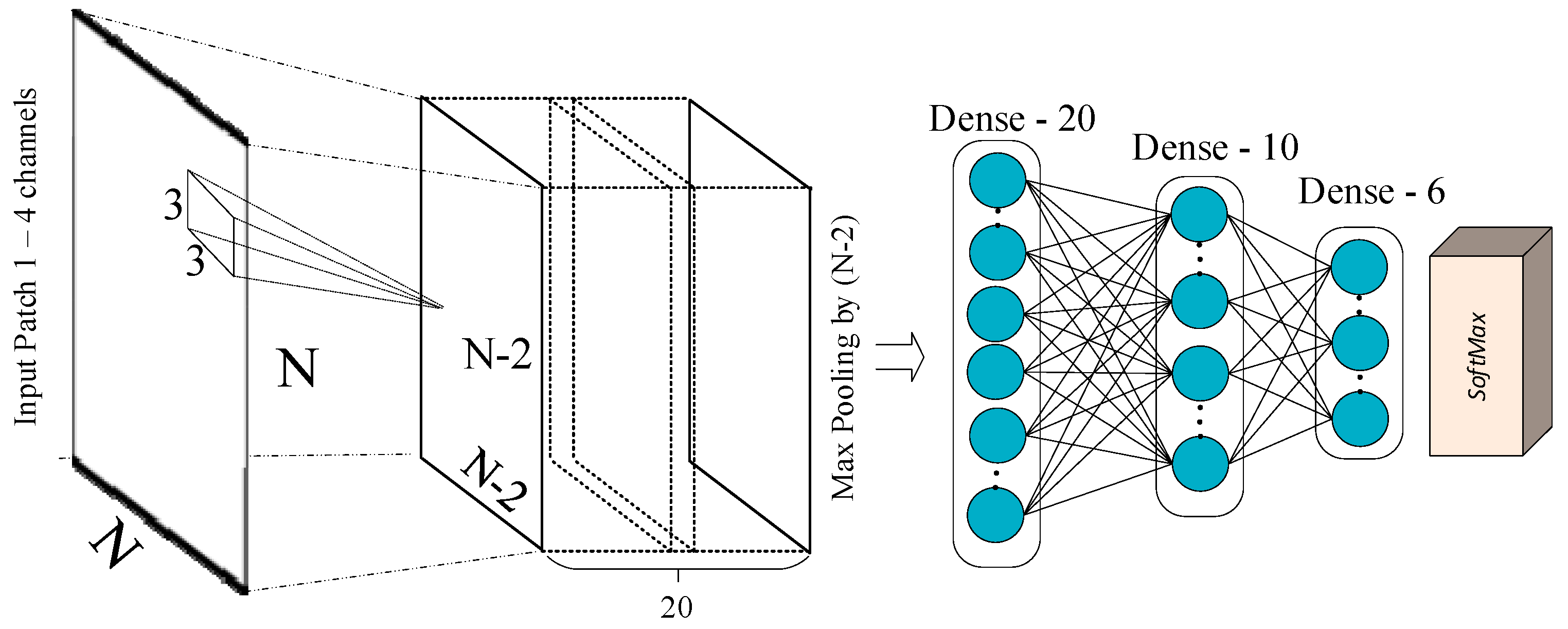
In order to obtain the final segmentation mask in Figure 1, an NxN window of each individual electromagnetic (EM) channel data around each pixel has been fed as the input to an adaptive 2D CNN, and the corresponding output of the CNN determines its center pixel’s label. The CNN configuration used in the proposed classification system is given in Figure 2. Accordingly, the used number of EM channels determines the size of the input layer of the CNN. We have tested 1 to 4 EM channels, and the results will be discussed in Section 4. One hyper-parameter in this model is the size (N) of the NxN sliding window. In deep-learning approaches, N has to be kept high due to numerous convolution and pooling layers in the deep network structures. However, the proposed compact network enables the user to set N as low as 5, and we will discuss the effect of the window size over the classification performance in Section 4. In the following sub-sections, we will present the proposed adaptive CNN topology, more detailed description of the network structure and the formulation of the back-propagation training algorithm for the SAR data are given in Appendix A.

3.1. Adaptive CNN Implementation

In the proposed adaptive CNN implementation, in order to simplify the network and achieve an adaptive configuration, several novel modifications are proposed as compared to conventional deep CNNs. First of all, the network encapsulates only two distinct hidden layer types: (1) “CNN” layers into which conventional “convolutional” and “subsampling-pooling” layers are merged, and, (2) fully-connected (or “MLP") layers. By this way, each neuron within CNN layers has the ability to perform convolution and down-sampling. The intermediate output of each neuron is sub-sampled to obtain the final output of that particular neuron. The final output maps are then convolved with their individual kernels and further cumulated to form the input of the next layer neuron. In Appendix A.1, the simplified CNN analogy is given where the image dimension of its input layer is made independent from CNN parameters.
The number of hidden CNN layers can be arbitrarily, regardless of the input patch size. The proposed implementation makes this possible by adjusting the sub-sampling factor of the intermediate outputs of the last hidden convolutional layer to produce scalar values as the input of the first MLP layer. For example, if the feature maps of the last hidden convolutional layer are 8 × 8 as in the figure at layer l+1, then, they are sub-sampled by a factor of 8. Besides sub-sampling, note that the dimension of the input maps is gradually decreasing due to the convolution without zero padding. As a result, after each convolution operation, the dimension of the input maps is reduced by (Kx−1, Ky−1) where Kx and Ky are the width and height of the convolution kernels, respectively. Each input neuron in the input layer is fed with the patch of the particular channel. As discussed earlier, in this study the number of channels is varied from 1 to 4. In general, it is determined by the data; for example, the available single intensity is directly used with one-channel CNN setup for single-polarized SAR data. In addition, the HSI channels are added to the input with four-channel setup, and it is revealed in Section 4.3 that adding HSI channels improves the accuracy obtained using single channel. Next, for the dual-polarized intensity data, two available channels are used as the input of the CNN.

3.2. Back-Propagation for Adaptive CNNs

The illustration of the BP training of the adaptive CNNs is shown in Figure 3. For an NL-class problem, the class labels are first converted to the target class vectors using 1-of-NL encoding scheme. By this way, for each window, with its corresponding target and output class vectors,   [ t 1 , , t N L ] and [ y l L , , y N L L ] , respectively, the MSE error in the last layer is expressed as in Equation (2). Next, derivative of this error with respect to individual weights and biases is computed. The BP formulation of the MLP layers is identical to the traditional BP for MLPs and hence it is skipped in this paper. On the other hand, the BP training of the CNN layers, composed of four distinct operations is detailed in Appendix A.2.
E = E ( y 1 L , ,   y N L L ) =   i = 1 N L ( y i L   t i ) 2

4. Experimental Results

In this section, we will first introduce our benchmark dataset used in the experiments and continue with the experimental setup. Next, the proposed compact adaptive CNNs will be analyzed against the state-of-the-art method in [18] with a comprehensive set of experiments. Performance evaluations will be presented in terms of visual inspection of the final obtained segmentation masks and quantitative analysis by comparing the overall classification accuracies and individual class accuracies of the proposed approach versus the competing method in [18]. Furthermore, precision, recall, and F1 Score of each class are calculated for the multi-class case by the following. The precision of class c is the proportion of correctly classified samples of class c among all samples that are classified by the classifier as c, where recall is the proportion of correctly classified samples of c among true samples of class c. Consequently, F1 Score =   2 × P r e c i s i o n × R e c a l l / ( P r e c i s i o n   + R e c a l l ) . Furthermore, the Cohen’s Kappa coefficient [55] is used as another performance measurement metric to analyze the reliability of the proposed system against deep CNN methods. Moreover, the sensitivity of the proposed approach with respect to the two hyper-parameters, the window size (N) and number of input channels will be investigated. Finally, we will conclude this section by demonstrating the performance gain of such compact configuration against deep network structures through sensitivity analysis with respect to the number of neurons and layers.

4.1. Benchmark SAR Data

In this study, two benchmark SAR data are used for our testing and comparative evaluations. The details of these benchmark SAR data are presented in Table 1. The first set of SAR data is for the Po Delta area located in the Northeast of Italy, and acquired at X-band and single-polarization mode. The second is the Dresden area in the Southeast of Germany at X-band and dual-polarization mode. The Po Delta area mainly consists of urban and natural zones, and the Dresden area has vegetation fields with man-made terrain types. The total number of samples in the whole ground truth (GTD) and the train data are presented in Table 2 for each SAR data.
As used GTD in this study is hand-labeled, it is almost impossible to provide 100% accuracy on the ground truth labels. However, this is also true with the other (competing) methods. Therefore, if there is a labelling error (which is the most probably case), this will affect all the methods equally. On the other hand, no ML method will tolerate on the high labelling errors since they are all “supervised” methods and if the supervision is erroneous at large then this will deteriorate the performance of the method, including the proposed method in this study.

4.1.1. Po Delta, COSMO-SkyMed, and X-Band

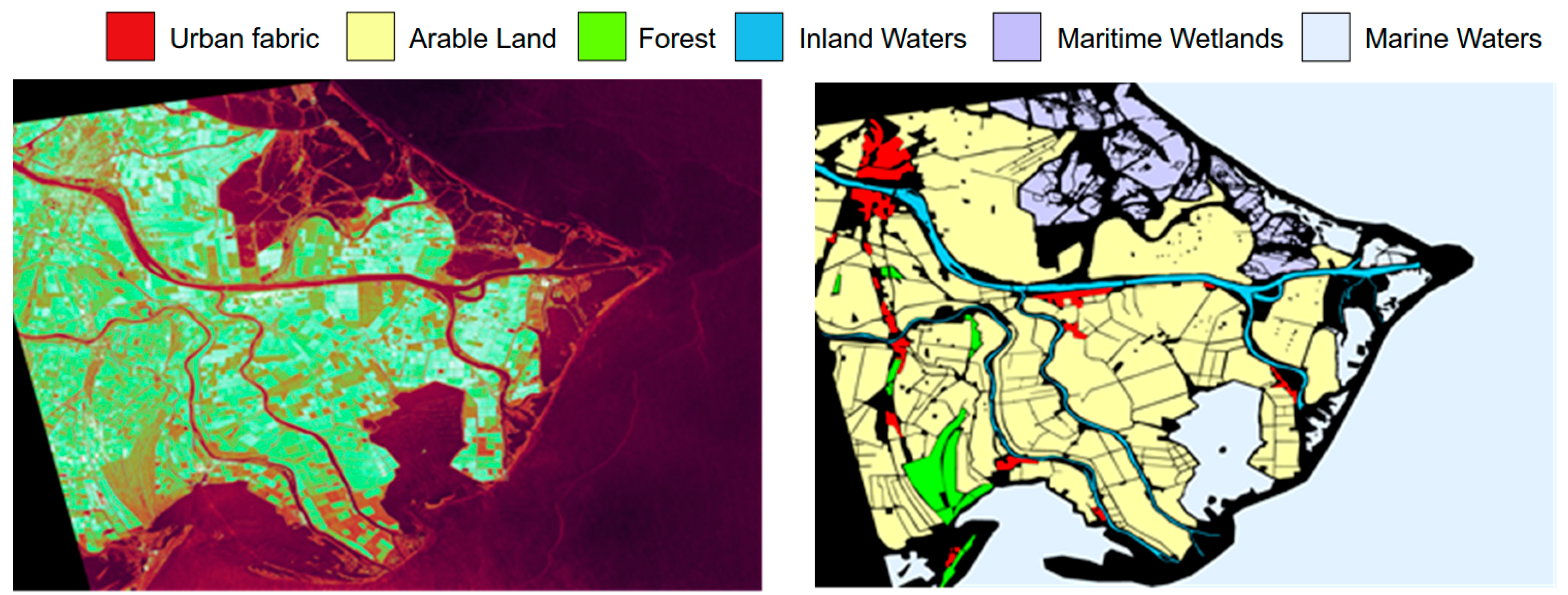
This benchmark single polarized SAR data covers the Po Delta area which mainly provides natural class information with different types of water classes for our experiments. It has only one polarization (HH) in Strip Map HImage mode with original size of 16,716 × 18,308 and a 3-meter resolution. Due to computational reasons in [18], the data is downscaled by 3.6 × 5.8. The same procedure is followed in this study as well to make comparison possible with the same GTD is used. The ground truth of this data is constructed by visually inspecting optical image data with the help of [56]. This data consists of mainly natural terrain types, such as several water-based terrain and soil-vegetation classes, some man-made structures which are grouped in one class. Consequently, we have determined six-classes which are urban fabric, arable land, forest, inland waters, maritime wetlands, and marine waters, and our constructed ground truth corresponds to the same GTD used for the previous state-of-the-art study in [18]. A pseudo colored image is generated by assigning HSI channels (obtained by [54]) to RGB channels, as shown in Figure 4 with its corresponding ground truth. For a fair comparison with [18], in this study we also used the same samples for training, which are randomly chosen from the ground truth (2000 pixels per class) as 1 % 2 % of the whole ground truth, corresponding to 0.08% of the entire data.

4.1.2. Dresden, TerraSAR-X, and X-Band

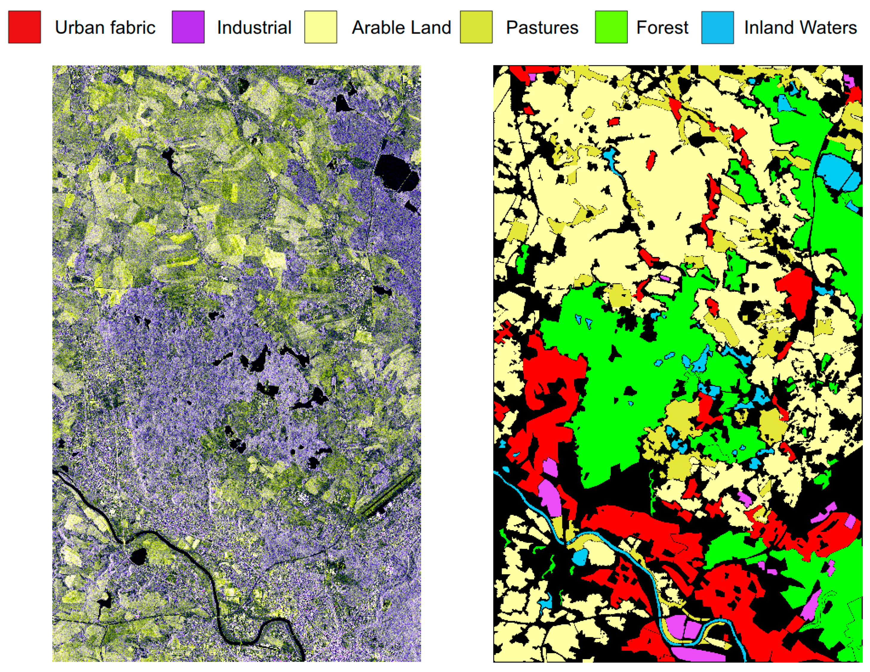
Dresden SAR intensity data has 4419 × 7154 pixels with approximately 4 × 4 meters square pixel resolution. It was acquired in Strip Map mode with dual-polarization (VH/VV), and it is radiometrically enhanced (RE) Multi-Look ground range detected (MGD) with effective number of looks 6.6. In MGD mode, coordinates are projected to the ground range, and each pixel is represented with its magnitude only, where the phase information is lost. However, MGD and RE provide speckle noise reduction. Because of the aforementioned reason for Po Delta data, this data is also downscaled by 2 × 2. Ground truth of this data is also manually constructed as explained before by using [56] as a reference and optical image data. It is the same GTD used also in [18] and consists of six classes which are urban fabric and industrial as man-made terrain types, arable land, pastures, forest, and inland waters as natural terrain types. The GTD is shown in Figure 5 by assigning distinct RGB values to each terrain class. In our experimental setups, we have used randomly chosen 1000 pixels and 100,000 pixels per class for training and testing (train/test ratio: 0.01), respectively, which was followed by the competing method [18].

4.2. Experimental Setup

Due to radiometrically enhanced multi-look ground range processing of the dual polarized TerraSAR-X image, speckle filtering is not performed for this dataset, whereas the Po Delta COSMO-SkyMed single polarized image is filtered for speckle noise removal. Hyper-parameters of the proposed adaptive CNN are selected by using 50% of the training data as the validation set.
Implementation of the proposed 2D CNN is done using C++ with MS Visual Studio 2015 in 64-bit. Although this is not a GPU based implementation, multithreading is possible with Intel ® OpenMP API with a shared memory. Overall, all experiments in this work performed by an I7-4790 CPU at 3.6GHz (4 real, 8 logical cores) with 16 GB memory. Experiments with Xception and Inception-ResNet-v2 are performed using Keras [57] with Tensorflow [58] backend in Python. We use a workstation with four Nvidia® TITAN-X GPU cards, 128 GB system memory, and Intel ® Xeon(R) CPU E5-2637 v4 at 3.50 GHz.
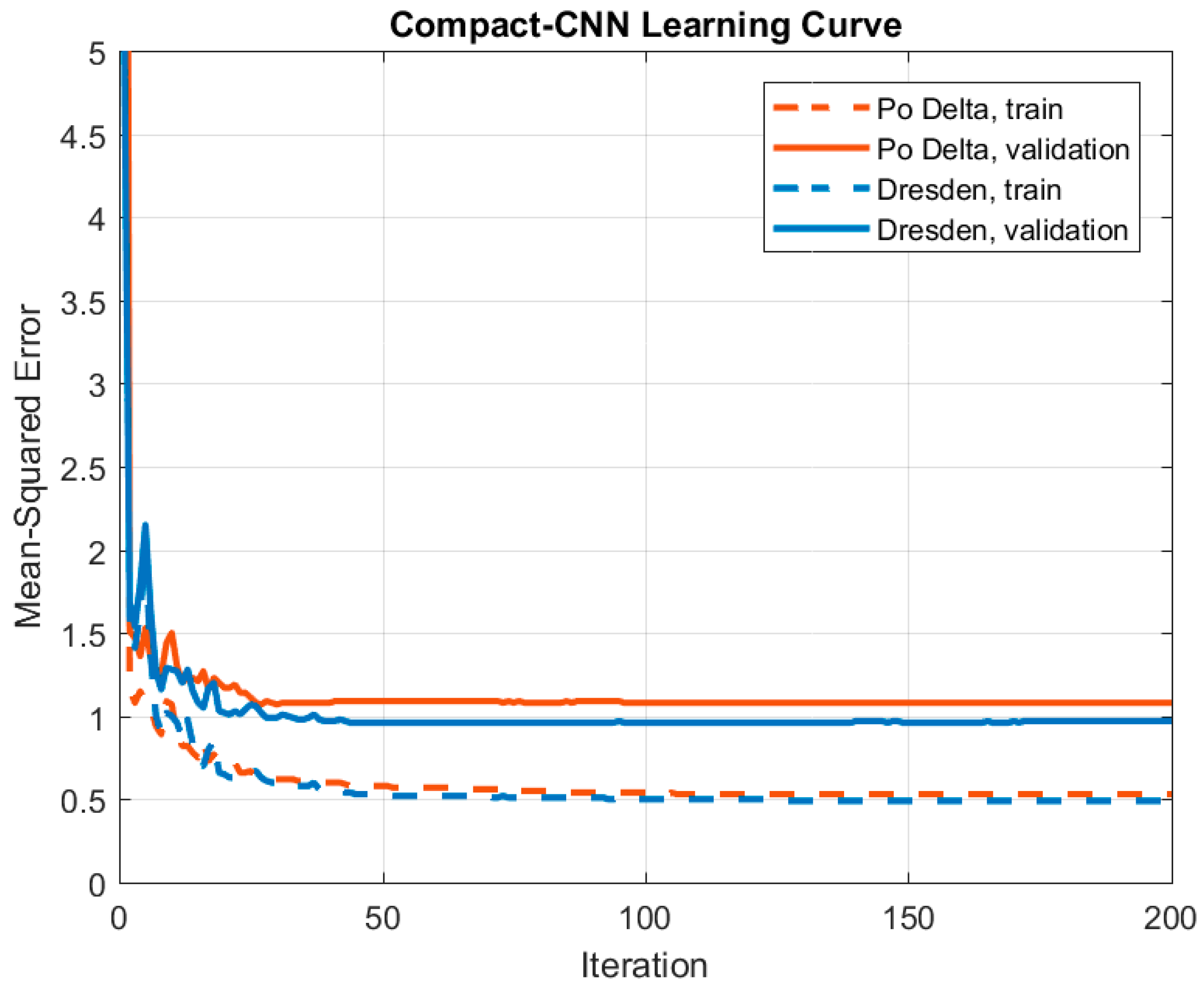
The CNN network is configured with a single hidden CNN and MLP layers with 3 × 3 convolution filters. The subsampling factor is two for the CNN layer. Due to its compactness, even with a limited training set, over-fitting does not pose any threat during training, and, therefore, we have only used the maximum number of training iterations as the sole early stopping criterion, which is 200 for both datasets. The convergence curve of the network with the proposed configuration is given in Figure 6. In the figure, half of the training data is used for the validation for both datasets. Since the training data is limited (<0.08 % and <0.076 % of the Po Delta and Dresden data), it is hard to draw a conclusion regarding the convergence of the network. However, the figure demonstrates that the proposed compact configuration is able to converge within 200 iterations, and over-fitting does not occur during the training process. One fact that, because of dynamic adaption of the learning rate ε, its initial value is not a game changer during the BP process, though, we set initially as 0.05. For instance, MSE is watched during the training process, and if it drops in the current iteration, then ε increases by 5%. On the other hand, it is decreased by 30% for the contrary case in the next iteration.

4.3. Results and Performance Evaluations

The test and performance evaluation of the proposed systematic approach for classification of SAR data are performed over each benchmark dataset. The comparative evaluations against the state-of-the-art method in [18] are performed in terms of overall classification accuracy, and in particular, we report each individual performance improvement per terrain class. As discussed earlier, the improvements are analyzed both quantitatively by classification accuracy and qualitatively by visual inspection. Lastly, to compare the proposed approach with deep CNNs, two recent state-of-the-art deep learners, Xception and Inception-ResNet-v2 [36,37], will be used.

4.3.1. Performance Evaluations over Po Delta Data

The Po Delta data consists of six classes and has an emphasis on natural classes. We have varied the sliding window size N from 5 × 5 to 27 × 27 to investigate its effect on the classification accuracy and the ability to produce finer details in segmentation masks. Hence, the overall classification accuracies are presented in Table 3 with different settings of N and different number of channels. The results clearly indicate that using only HH backscattering coefficient, the proposed approach with the adaptive 2D CNN outperforms the best performance of the state-of-the-art method [18] with a significant gap (>10%), despite the fact that the competing method uses higher dimensional (>200-D) composite feature vector (color + texture + HH). For a more fair comparison, if both methods use the same information (i.e., with only HH channel), the performance gap between the proposed approach and [18] exceeds 40%.
When additional input information is used in the proposed approach, further performance improvements can be achieved. For instance, when HSI components are used as distinct input channels, around 1% improvement in the accuracy is obtained with parameter N = 25, which is the optimal window size. However, with any N setting which is higher than 9, the proposed approach can achieve >75% accuracy. One can also observe the fact that the classification performance is not improving with four-channel setup after N = 25.
Furthermore, confusion matrix is given in Table 4. It can be observed from the confusion matrix that the most confused terrain types are maritime wetlands and marine waters. This is expected, since they are not even distinguishable with the human eye, and have similar characteristics.
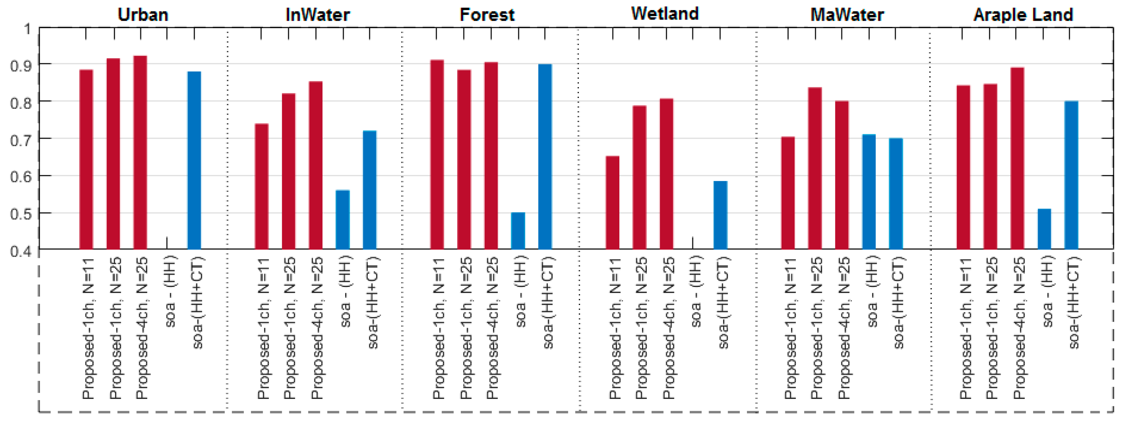
Additionally, for a detailed comparison, the classification accuracy for each terrain type is presented in Figure 7. In the figure, the blue two bar plots on the right display the best results obtained by the state-of-the-art method using HH channel and 208-D features in [18], whereas the bar plots on the left represent the results for the proposed method with one-channel and four-channel setups. While the classification performance of each terrain type is improved, a significant performance gap occurs e.g., for inland waters, maritime wetlands, marine waters, and arable land. Notably, the classification performance of some terrain types such as wetland is improved by >20%, which justifies the earlier argument that manually selected features cannot provide the same discrimination power for all classes, whilst the proposed adaptive CNN can “learn to extract” such features. Since, in the competing method, a significant performance gap occurs among the terrain types, the reliability eventually becomes a serious issue in [18] whereas the proposed method can always achieve >80% accuracy for any terrain type.
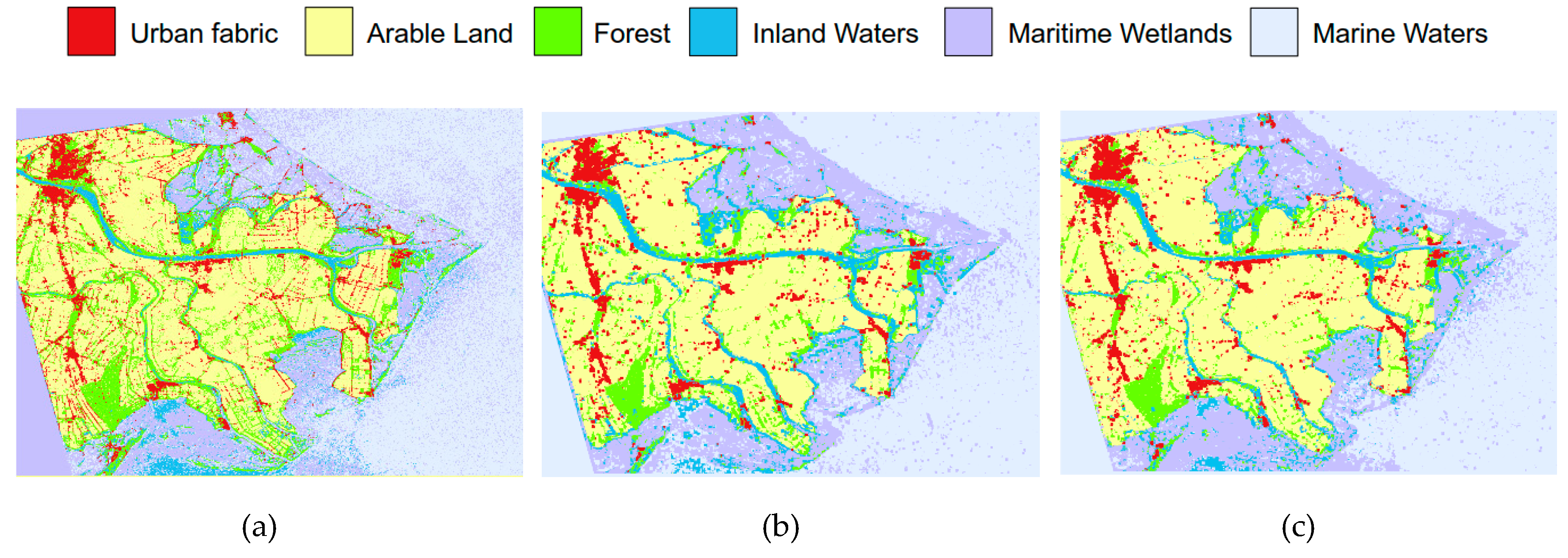
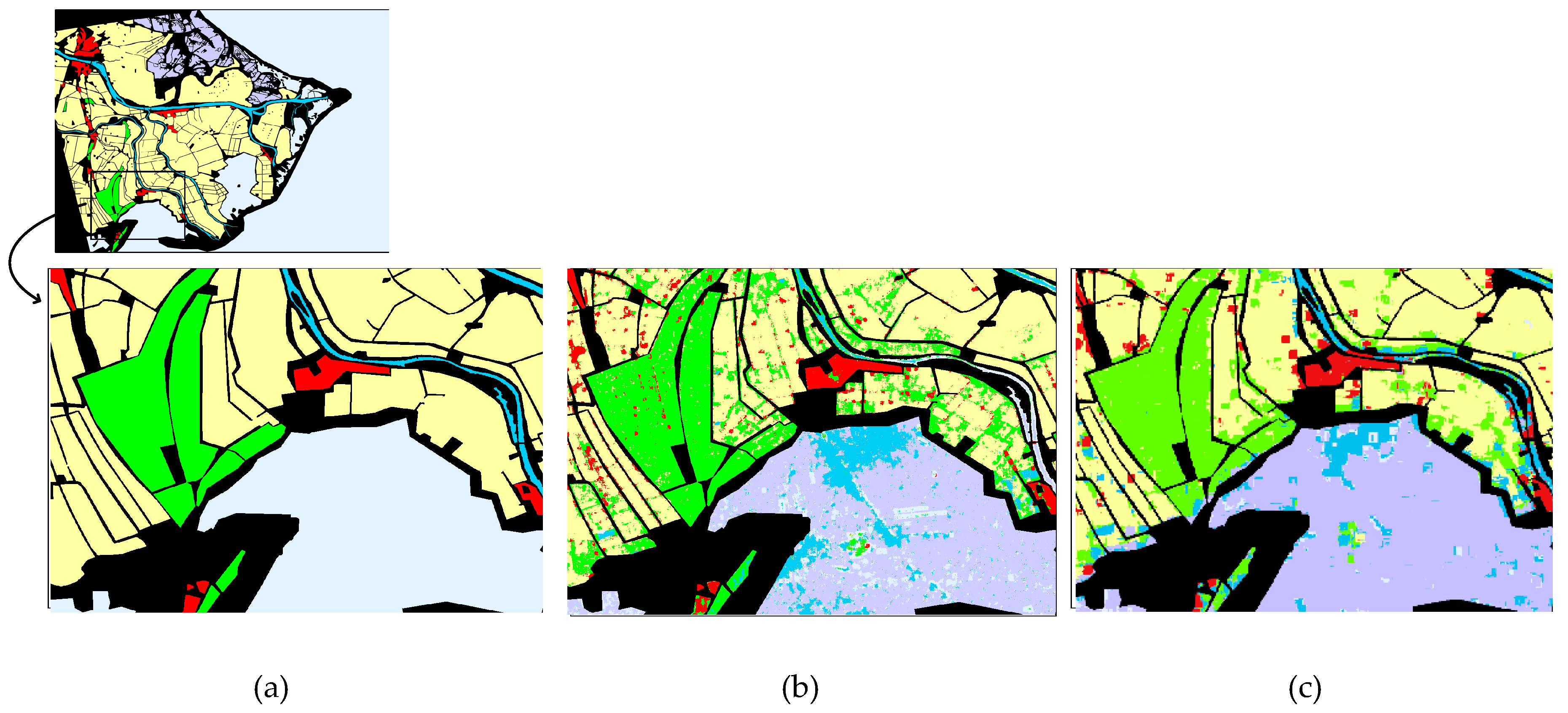
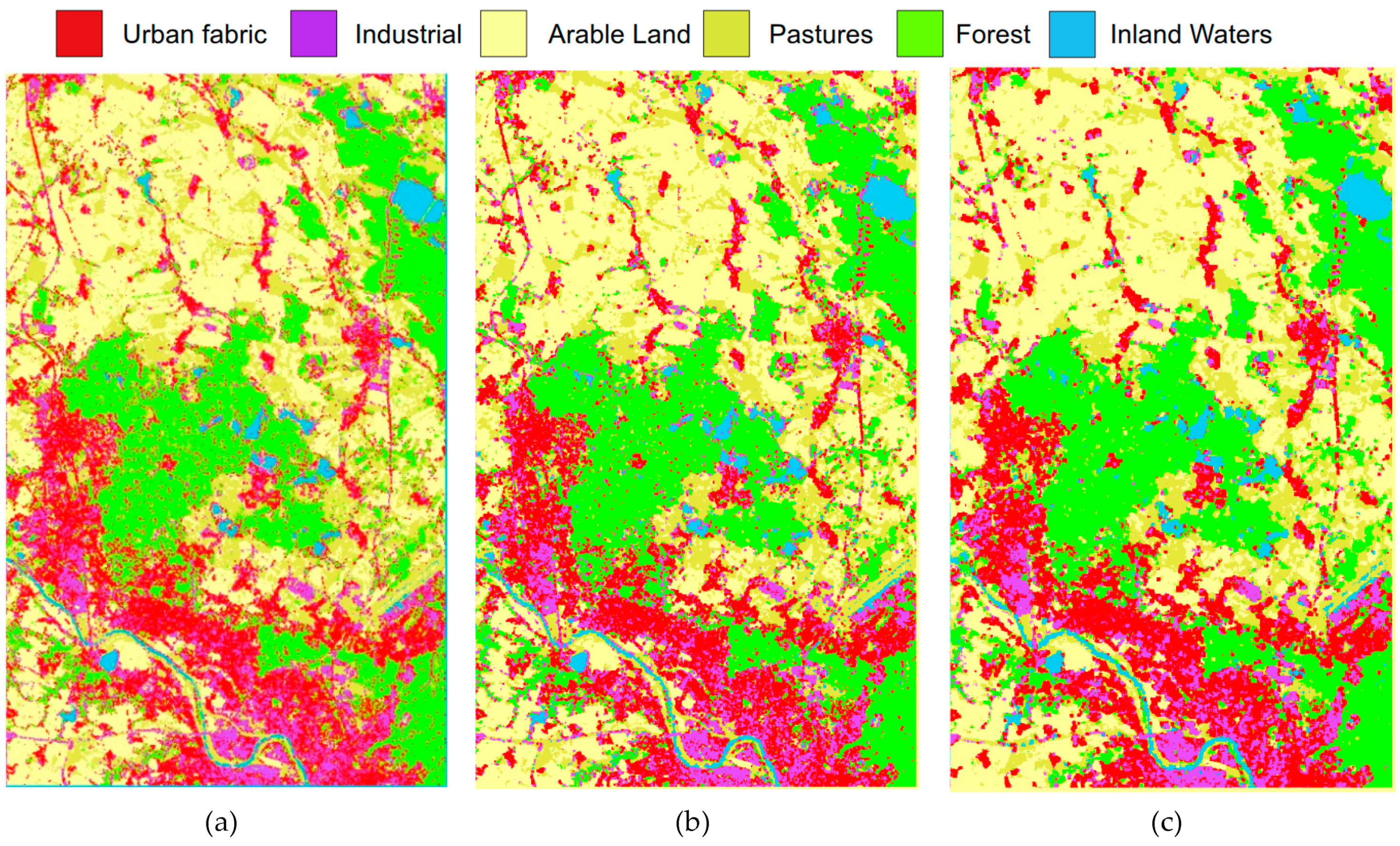
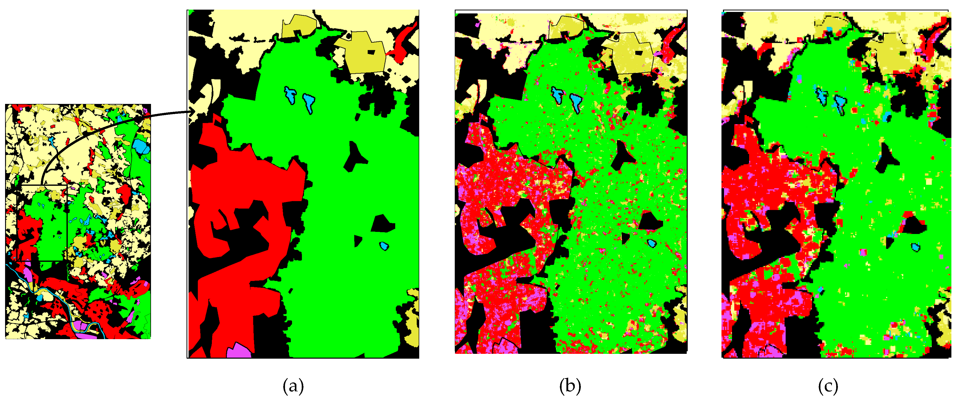
For visual evaluation, the final segmentation masks for Po Delta SAR data are given in Figure 8 with their corresponding overlaid regions with the ground truth. The previous quantitative analysis made based on the overall accuracies in Table 3 has shown that using larger window sizes generally increases the overall accuracy. However, an important observation from the final segmentation masks in Figure 8 is that there is a trade-off between choosing the quantitatively and qualitatively good results. Consider that the optimal window size is 25 × 25 in Table 3, whereas the segmentation mask suffers from the sliding window artifacts for this case in Figure 8. On the other hand, the setup with 11 × 11 pixels window can achieve finer details in the final mask. The overlaid regions in the figure can be directly compared with overlaid regions of the competing method in Figure 9. Hence, Figure 9 shows that forest class is mostly confused with urban fabric by the competing method in [18]. Moreover, it can be said that arable land is misclassified as urban fabric and forest in general by [18]. Comparison of Figure 9 with Figure 8 further reveals that the classification performance for each terrain type is highly improved by the proposed method. This is also confirmed by a detailed visual evaluation over the zoomed section shown in Figure 10. Accordingly, the classification performance of each class (especially urban fabric, forest and arable land) is improved and the segmentation noise (error) has been removed almost entirely.

4.3.2. Performance Evaluations over Dresden Data

The Dresden data has also six classes, but it has more man-made structures compared to the Po Delta. For the performance evaluation, we have again varied the window size N from 5 to 27 to investigate its effect on the classification performance. The overall classification accuracies are presented in Table 5. Note that on this dataset, the best accuracy achieved is 81.33% with the window size, 21 × 21 pixels using only VH/VV channels as two-channel input, and the accuracy starts to decrease after N = 21 This reveals the advantage of using such small window sizes in the classification performance. The competing method [18] can also achieve the top performance around 81%–82% using 209-D features (VH/VV + color + texture). In a more fair comparison, when both methods use the same SAR information (VH/VV channels as two-channel input) the proposed approach achieves a significant performance gap greater than 30%.
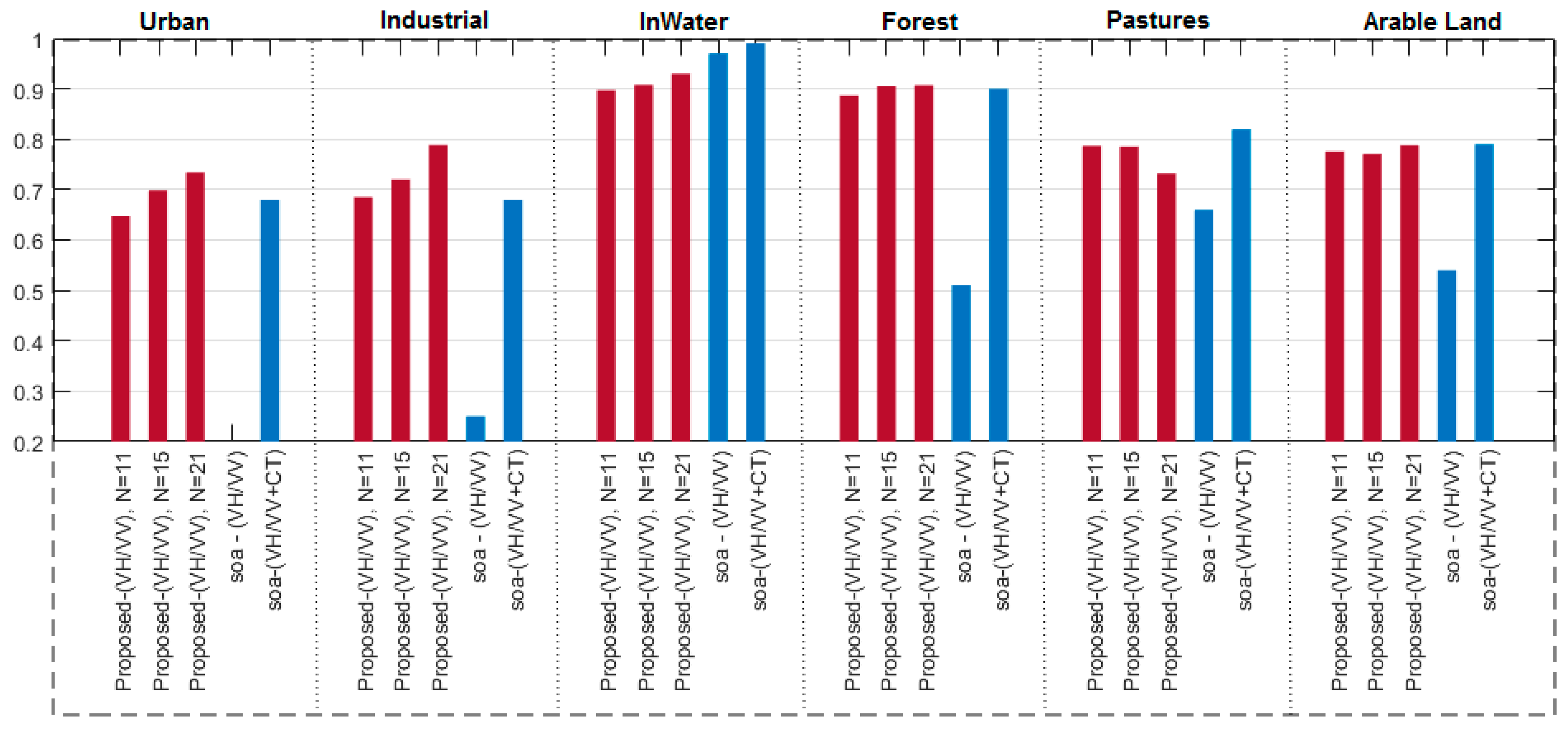
The confusion matrix of six classes given in Table 6 shows that urban fabric is confused mostly by industrial terrain type, while pastures confused with arable land. This is also expected because of similarities between those terrain types, and this may reveal the fact that the multi-label classification would be possible for these terrains in this dataset. For a detailed comparison, the classification accuracy for each terrain type is plotted in Figure 11. The performance of the proposed approach with two-channel input is compared against the best results obtained by the competing method using the composite 209-D features. The proposed approach achieves similar or better classification accuracy except for inland water terrain type. Again, for a more fair comparison where each method uses the same information (i.e., only VH/VV channels), the performance gap becomes substantial and exceeds 50% for urban and industrial classes.
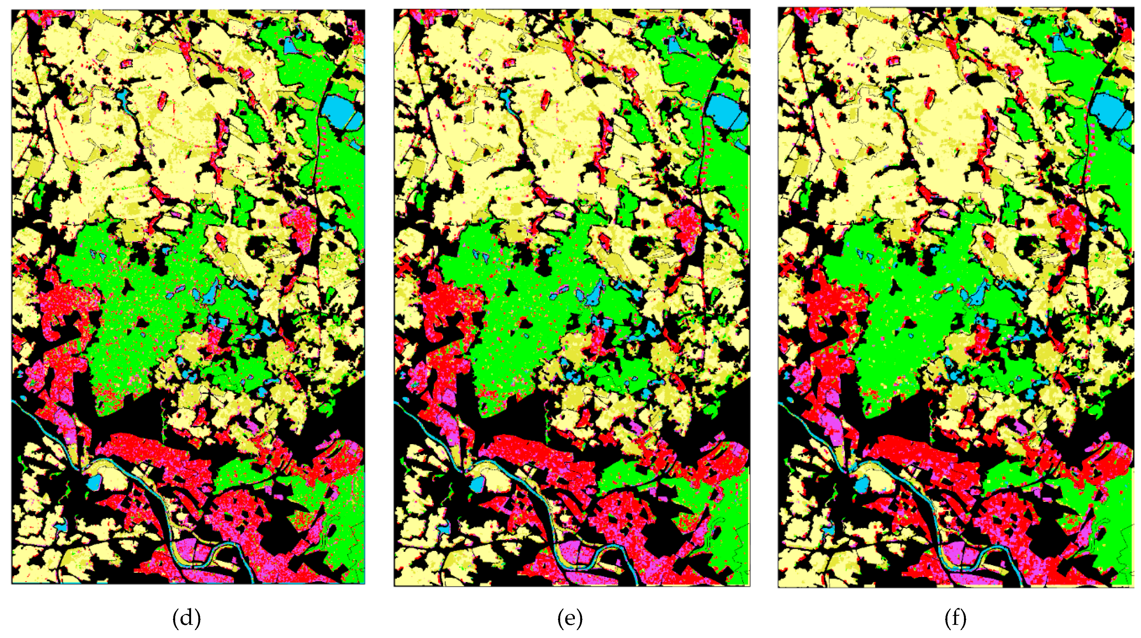
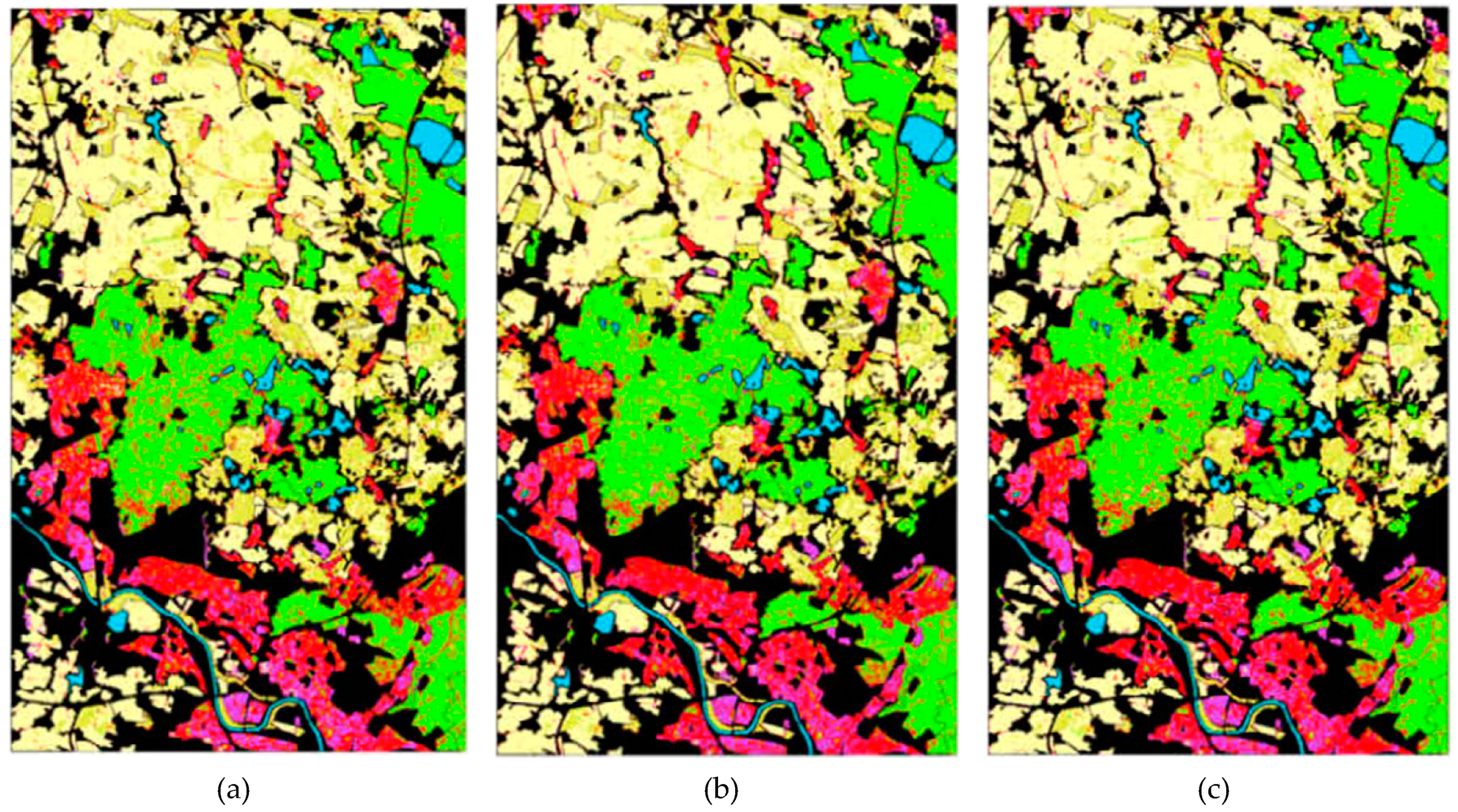
Segmentation masks of the proposed approach and their corresponding overlaid regions with the ground truth for the Dresden data are given in Figure 12. As before, overlaid regions can be compared with the results of the competing method in Figure 13. Similar observations can be made, i.e., considering the best classification results of both methods using overlaid regions over the corresponding ground truth as illustrated in the figures. In Figure 14, it is clear that the competing method suffers from a high classification noise, whereas the proposed approach has significantly reduced the noise level especially for forest, pastures, and arable land classes. It is worth to mention that the best window size N is 21 for the Dresden data, and the classification accuracy is not increasing with larger values of N.

4.3.3. Deep versus Compact CNNs

Two recent deep CNNs, Xception and Inception-ResNet-v2 [36,37], are compared against the proposed method. As mentioned before, such deep CNNs are not suitable for small dimensional window sizes as we use in this study. The input dimensions should be at least 71 × 71 and 75 × 75 for Xception and Inception-ResNet-v2 models because of their depths. To address this limitation, we have to up-sample each input patch by bilinear interpolation.
For the training, both networks are trained from scratch using stochastic gradient descent as optimizer with the following training parameters: batch size: 32; momentum: 0.9; initial learning rate: 0.045; and the learning rate is decayed with the rate of 0.94 every two epochs. Overall, Xception has been able to converge after 400 epochs, while Inception-Resnet-v2 has needed 160 epochs. Furthermore, we apply transfer learning to investigate if the pre-trained versions of the networks by ImageNet dataset [41] will increase the classification performance. During the training process of transfer learning approach, we first freeze those ImageNet layers and train randomly initialized first convolutional layers and MLP layers of Xception and Image-Resnet-v2 networks for 25 epochs using the above training parameters. After this process accomplished, we fine-tune all layers of the networks with a smaller learning rate as 0.001, with 0.94 decaying factor every two epochs for 75 epochs.
Finally, the classification accuracies of Xception, Inception-Resnet-v2, and the proposed compact CNN approach are given in Table 7 and Table 8 for the Po Delta and Dresden datasets, respectively. It is clear that deep CNNs cannot outperform such compact model with limited training data. Additionally, the ability to work with small window sizes are clearly shown in Table 8 for the Dresden data. There is >20% performance gap between the deep CNNs and the proposed approach in the classification accuracy for 5 × 5 window size. On the one hand, the proposed approach cannot outperform Inception-ResNet-v2 with 27 × 27 window size over Dresden data. However, such large window sizes do not produce high-detailed segmentation masks as shown in the previous sub-sections.
Moreover, the performance comparison between deep and the proposed compact CNNs is performed over each class by calculating class specific precision, recall and F1 scores for the Po Delta and Dresden data as presented in Table 9 and Table 10, respectively. As the tables demonstrate, the proposed approach is able to produce at least 0.77 and 0.72 F1 Scores for Po Delta and Dresden, respectively, where the deep CNNs fail for the certain classes. This means that the reliability of the proposed system is achieved for all classes by the proposed approach, and the overall system reliability is further motivated in Table 11. As given in Table 11, the kappa coefficient of the proposed approach is higher than the deep CNN methods.

4.4. Sensitivity Analysis on Hyper-Parameters

Besides the major parameter, N, the proposed adaptive CNN topology has two additional hyper-parameters: the number of hidden layers and hidden neurons in each layer. In the aforementioned experiments, we use a CNN configuration that has one hidden CNN and one MLP layer, with 20 and 10 hidden neurons, respectively. Note that the input and output layer sizes are determined by the underlying classification problem. In this section, we will analyze the network hyper-parameter sensitivity by varying them significantly. For this purpose, we define m as the multiplier for the number of neurons in the hidden layers and n as the multiplier for the number of hidden CNN layers, respectively. Hence, we vary the network hyper-parameters by keeping the best window size for each SAR data unchanged. For example, m = n = 1 corresponds to the default setup, and if m = 4 and n = 2, the network would have two hidden CNN layers with 4 × 20 = 80 neurons each, and 4 × 10 = 40 neurons for hidden MLP layer (i.e., [In-80-80-40-Out]). The classification accuracies provided in Table 12 demonstrate that when the network configuration varies, the accuracy varies slightly in a margin around ±3%. This shows that the proposed approach is robust to variations of the network hyper parameters in general. Moreover, increasing the number of hidden layers slightly degrades the performance whilst the best classification performance is achieved with a single hidden CNN/MLP layer, each of which has 4× more hidden neurons than the default setup. With this configuration, the top performance of the default setup can further be improved by about 2%, which demonstrates the superiority of the proposed method in both datasets.

4.5. Computational Complexity

Computational complexity of forward propagation (FP) and backward propagation (BP) is analyzed by first computing total number of operations at each CNN layer and cumulating them to obtain total computational complexity. Let N l 1 N l number of connections between the current layer l and previous layer l − 1, and s l l 1 is the size of the previous layer output. If the boundary conditions are ignored, convolutions with kernels in w l l 1 dimension form the total number of operations, when the bias operations are ignored. Hence, during the FP, the total number of multiplications and additions at the layer l is calculated as follows:
N m u l l = N l 1 N l s l l 1 ( w l l 1 ) 2 , N a d d 1 l = N l 1 N l s l l 1 ( w l l 1 1 ) 2 , N a d d 2 l = N l 1 N l s l l 1 .
Consequently, overall number of multiplications and additions, T m u l F P and T a d d F P of an L layer CNN is obtained as:
T m u l F P = l = 1 L N l 1 N l s l l 1 ( w l l 1 ) 2 , T a d d 1 F P = l = 1 L N l 1 N l s l l 1 ( w l l 1 1 ) 2 , T a d d 2 F P = l = 1 L N l 1 N l s l l 1 .
During the BP, there are two convolutions as shown in Equations (A7) and (A14). The first convolution is between the delta error in the next layer, Δ i l + 1 , and the rotated kernel,   r o t 180 ( w k i l ) , in the current layer, l. Let x l l be the size of both the input, x i l , and also its delta error, Δ i l , of the ith neuron. The convolution in Equation (A7) consists of x l l + 1 ( w l l ) 2 multiplications and x l l + 1 additions. Thus, again ignoring the boundary conditions, the total number of multiplications and additions coming from the first convolution within a BP iteration will be:
T m u l B P 1 = l = 0 L 1 N l + 1 N l x l l + 1 ( w l l ) 2 , T a d d 1 B P 1 = l = 0 L 1 N l + 1 N l x l l + 1 ( w l l 1 ) 2 , T a d d 2 B P 1 = l = 0 L 1 N l + 1 N l x l l + 1 .
The second convolution of a BP iteration given in Equation (A14) is performed between the current layer output, s k l , and next layer delta error, Δ i l + 1 where w l l = x l l + 1 s l l . The number of additions and multiplications of each connection will be, w l l and w l l ( x l l + 1 ) 2 , respectively. Similarly, the total number of multiplications and additions coming from the second convolution will be:
T m u l B P 2 = l = 0 L 1 N l + 1 N l w l l ( x l l + 1 ) 2 , T a d d 1 B P 2 = l = 0 L 1 N l + 1 N l w l l ( x l l + 1 1 ) 2 , T a d d 2 B P 2 = l = 0 L 1 N l + 1 N l w l l .
Finally, the total number of operation during a BP iteration will be ( T m u l F P + T m u l B P 1 + T m u l B P 2 ) and ( T a d d 1 F P + T a d d 2 F P + T a d d 1 B P 1 + T a d d 2 B P 1 + T a d d 1 B P 2 + T a d d 2 B P 2 ) , respectively. Apparently, the overall complexity of the network consists of mostly the first part rather than the additions, and contribution from the MLP side of the network is insignificant. Because, only a scalar multiplication and addition are performed for each connection and the computational complexity of MLPs is well-studied [59].
Considering inference complexity of the network, T m u l F P = 4 × 20 × 25 × 25 × 9 = 450 K , T a d d 1 F P = 4 × 20 × 25 × 25 = 50 K , and T a d d 2 F P = 4 × 20 × 25 × 25 × 8 = 400 K based on Equations (4)–(6). Consequently, the total number of operations would equal to 900K which requires only 0.0009 GFlops computing sources and shows the suitability of such compact networks for real-time applications. This is substantially smaller than typical deep CNNs, compared that Xception has 8380 M and Inception-ResNet-v2 has 13,200 M number of operations [60]. Examples can be extended: GoogleNet’s [61] every inception modules has greater than 50M operations, in total it has 1501 M operations, and Residual nets [62] proposed originally to have lower complexity using short-cuts even though it has more layers than typical deep nets. However, their network still needs 1.8 GFlops to 11.3 GFlops for 18-layers to 152-layers.

5. Conclusions and Future Works

In this study, we propose a novel approach for fast and accurate classification of single- and dual-polarized SAR intensity data especially when the labeled data is scarce (e.g., <0.1% of the SAR data). For this purpose, the proposed system is designed using adaptive and compact CNNs which are capable of learning from such limited training data with small-size patches. The proposed system exhibits crucial advantages over conventional and Deep Learning (DL) methods: first, the computational complexity is greatly reduced, making the proposed algorithm more efficient and more suitable for real-time deployment. Second, the accuracy and the details in the segmentation mask are both improved since the correlation between pixels in high-resolution SAR images tends to decrease when the patch size increases. Finally, as opposed to existing DL methods which require the use of a large partition of SAR data for training, the proposed approach only uses a small amount of (labelled) SAR data for training (e.g., <0.1%) and hence minimizes the labor and cost intensive labelling process for accurate classification. The latter deficiencies also prevent direct comparison of the proposed approach against the DL methods. The recent state-of-the-art method, [18], which can also function with minimum training and small patches, is proposed to extract color and texture features to have a very high dimensional composite feature vector that is learned by a large ensemble of classifiers. The proposed approach was shown to achieve a superior classification performance using only one compact classifier with one to four input EM channels. Therefore, such an approach voids entirely the pre-processing step of feature extraction. Finally, the comparative evaluations further reveal that the proposed approach has an improved inter-class classification reliability and significantly less or no classification (segmentation) noise when tested over two X-band datasets. In the proposed method, the patch size N is an important hyper-parameter, where, N > 19 achieves the highest classification accuracy in both datasets. The sensitivity analysis over the hyper-parameters of the network also demonstrates that a good level of robustness is achieved against their variations. As for future work, further investigations will be performed over other datasets. Moreover, we believe that certain visual features, if properly adapted to the input layer of the CNN, can be used to further improve the classification accuracy. For this purpose, we will investigate the use of color and texture features as well as EM channels together.

Author Contributions

M.A. conceptualized the manuscript and wrote the major parts. M.A. and S.K. wrote the manuscript. S.K. contributed Section 3 and original draft preparation. T.I. and M.G. continuously provided suggestions, review, and editing.

Funding

This research received no external funding.

Acknowledgments

The SAR data by TerraSAR-X © Astrium Services’ GEO-Information Division (now under Airbus Defence and Space) and COSMO-SkyMed Product – © ASI [2007] processed under license from ASI – Agenzia Spaziale Italiana. All rights reserved. Distributed by e-GEOS.

Conflicts of Interest

The authors declare no conflict of interest.

Appendix A

Appendix A.1. Adaptive CNN Implementation

As Figure A1 shows the modified version of “CNN layers”, the CNN analogy is simplified and the image dimension of its input layer is made independent from CNN parameters. In the figure, s k l is obtained by sub-sampling the intermediate output of kth neuron at layer l, y k l , and each s k l convolved with their corresponding weight kernels to form input maps of the next layer’s neuron by summation, as follows:
x k l =   b k l +   i = 1 N l 1 c o n v 2 D ( w i k l 1 ,   s i l 1 , N o Z e r o P a d ) .
Figure A1. An adaptive CNN Implementation with kernel dimensions, Kx = Ky = 3, and subsampling factors, ssx = ssy = 2.
Remotesensing 11 01340 g0a1

Appendix A.2. Back-Propagation for Adaptive CNNs

Appendix A.2.1. Inter-BP among CNN Layers: Δ s k l Δ l l + 1

According to the basic rule of BP, if the kth neuron at the current layer l is connected to the next layer to obtain its ith input with weight w k i l , then the next layer’s delta Δ l l + 1 and the same weight will together form Δ k l of the neuron in the current layer l. This means:
E s k l =   Δ s k l   Σ   Δ l l + 1 ,   i { 1 , N l + 1 } ,
where, E is the mean-square-error (MSE). Specifically:
Δ s k l =   i = 1 N l + 1 E x i l + 1   x i l + 1 s k l =   i = 1 N l + 1 Δ l l + 1 x i l + 1 s k l ,
where:
x i l + 1 = +   s k l   w k i l + .
Let us focus on a single pixel’s contribution of the output s k l ( m , n ) , to pixels x i l + 1 ( m , n ) (assuming a 3 × 3 kernel for simplicity), since obtaining the derivative from the convolution is obviously not straightforward.
x i l + 1 ( m 1 ,   n 1 ) = +   s k l ( m , n ) w k i l ( 2 , 2 ) +   x i l + 1 ( m 1 ,   n ) = +   s k l ( m , n ) w k i l ( 2 , 1 ) + x i l + 1 ( m + 1 ,   n + 1 ) = +   s k l ( m , n ) w k i l ( 0 , 0 ) +
In Figure A2, the contribution of an output pixel, s k l ( m , n ) , over two pixels of the input map at the next layer’s ith neuron, x i l + 1 ( m 1 , n 1 ) and x i l + 1 ( m + 1 , n + 1 ) is indicated.
The delta of s k l ( m , n ) can be now written by treating the pixel as a MLP neuron and has a connection to the next layer, therefore, the rule of BP can be expressed as follows:
E s k l   ( m , n ) =   Δ s k l ( m , n ) =   i = 1 N l + 1 r = 1 1 t = 1 1 Δ l l + 1 ( m + r ,   n + t ) w k i l ( 1 r ,   1 t ) .
If we generalize it for all pixels of Δ s k l :
Δ s k l =   i = 1 N l + 1 c o n v 2 D ( Δ l l + 1 ,   r o t 180 ( w k i l ) , Z e r o P a d ) .
Note that due to the dimension reduction caused by convolution, it is necessary to do zero padding for each boundary of the Δ l l + 1 by (Kx−1, Ky−1), since we want Δ s k l and Δ l l + 1 have the same dimensions with the s k l .
Figure A2. Contribution of single output pixel s k l ( m , n ) to the two pixels at the next layer’s x i l + 1 with a 3 × 3 kernel.
Remotesensing 11 01340 g0a2

Appendix A.2.2. Intra-BP within a CNN Neuron: Δ k l Δ s k l

After performing the BP from the next layer, l+1, to the current layer, l, we should continue to back-propagate it to the input delta. If the up-sampled version of the map with zero order is represented as us k l =   up ssx , ssy ( s k l ) , then the input delta is obtained as follows:
Δ k l =   E x k l =   E y k l   y k l x k l =   E u s k l   u s k l y k l   f ( x k l ) = u p ( Δ s k l ) β   f ( x k l ) ,
where β = ( s s x , s s y ) 1 since each pixel of the output s k l was obtained by averaging ssx.ssy number of pixels of the intermediate output y k l . If “maximum pooling” is used as down-sampling, then Equation (A8) should be adjusted accordingly.

Appendix A.2.3. BP from the First MLP Layer to the Last Convolutional Layer
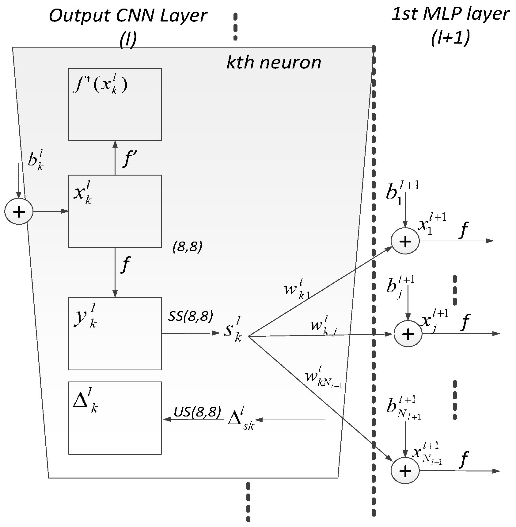
As illustrated in Figure A3, the last hidden convolutional layer is connected to the first MLP layer, and hence it produces scalar output, s k l . In other words, this particular layer’s sub-sampling factors are adjusted depending on the input map dimensions, i.e., (ssx = 8, ssy = 8) is chosen as in the figure, to always produce scalars. Correspondingly, each weight, w k i l , of this layer is also scalarly the same as a regular MLP and performing multiplication. Thus, the BP as the scalar case is demonstrated as follows in Equation (A9) from MLP layer to the CNN layer.
E s k l =   Δ s k l =   i = 1 N l + 1 E x i l + 1   x i l + 1 s k l =   i = 1 N l + 1 Δ i l + 1 w k i l ,
and intra BP to get: Δ k l B P   Δ s k l is identical to a regular BP for MLPs.
Δ k l =   E x k l = u p ( Δ s k l )   β   f ( x k l )
Figure A3. The output of the last hidden convolutional layer—first MLP layer.
Remotesensing 11 01340 g0a3
Finally, the sensitivities for the weight and bias, too, are identical to a regular MLPs:
E w k j l =   E x j l + 1   x j l + 1 w k j l =   Δ j l + 1 s k l E b k l + 1 =   E x k l + 1 x k l + 1 b k l + 1 =   Δ k l + 1 .

Appendix A.2.4. Computation of the Weight (Kernel) and Bias Sensitivities
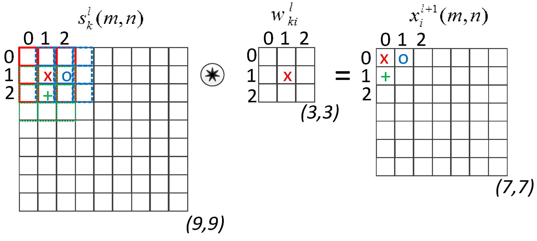
Computation of the updated bias of the ith neuron at layer l + 1 and all weights of the current layer that connected to the next layer is done based on the regular BP of MLPs by using the delta of the next layer’s ith neuron, Δ i l + 1 .
x i l + 1 =   b i l + 1   + +   y k l w k i l + E w k i l =   y k l Δ i l + 1   and   E b l l + 1 =   Δ i l + 1
The rule of thumb update rule of the BP states that the sensitivity of the weight connecting the kth neuron in the current layer to the ith neuron in the next layer depends on the output of the current layer neuron and the delta of the next layer neuron. For hidden neurons in a convolutional layer, a similar approach is followed to compute the weight and bias sensitivities.
Figure A4. Obtaining the input of the ith neuron, x i l + 1 , at the next layer, l + 1 by the convolution of the output of the kth neuron at the current layer, s k l , and weight, w k i l
Remotesensing 11 01340 g0a4
Figure A4 illustrates the evaluation of the input of the ith neuron, x i l + 1 , at the next layer l + 1 with the output, s k l , and weight, w k i l , of the current layer. One can write that each weight element’s contribution over the output:
x i l + 1 ( 0 , 0 ) =   +   w k i l ( 0 , 0 ) s k l ( 0 , 0 ) + w k i l ( 0 , 1 ) s k l ( 0 , 1 ) + w k i l ( 1 , 0 ) s k l ( 1 , 0 ) + x i l + 1 ( 0 , 1 ) =   +   w k i l ( 0 , 0 ) s k l ( 0 , 1 ) + w k i l ( 0 , 1 ) s k l ( 0 , 2 ) + w k i l ( 1 , 0 ) s k l ( 1 , 1 ) + x i l + 1 ( 1 , 0 ) =   +   w k i l ( 0 , 0 ) s k l ( 1 , 0 ) + w k i l ( 0 , 1 ) s k l ( 1 , 1 ) + w k i l ( 1 , 0 ) s k l ( 2 , 0 ) + x i l + 1 ( m , n ) =   +   w k i l ( 0 , 0 ) s k l ( m , n ) + w k i l ( 0 , 1 ) s k l ( 0 , n + 1 ) + w k i l ( 1 , 0 ) s k l ( m + 1 , n ) + x i l + 1 ( m , n ) =   r = 1 1 t = 1 1 w k i l ( r + 1 ,   t + 1 ) s k l ( m + r , n + t ) +
Due to the fact that each weight contributes to each neuron input, x i l + 1 ( m , n ) as seen in Equation (A13), the derivative is obtained by the summation of delta- output product for all pixels, as the following:
E w k i l ( r , t ) =   m n Δ i l + 1 ( m , n ) s k l ( m + r , n + t )                   E w k i l = c o n v 2 D ( s k l ,   Δ i l + 1 , N o Z e r o P a d )
As expected, the bias of kth neuron at layer l, b k l , also contributes to every pixel (all pixels in the map use the shared bias). Hence, the bias sensitivity will be the summation of pixel sensitivities in the map as expressed in Equation (A15).
E b k l =   m n E x k l ( m , n ) x k l ( m , n ) b k l =   m n Δ k l ( m , n )
Overall, for each patch in the training set in Figure 3, BP flow is given as follows:
(1)
Initialize weights (kernels) and biases (e.g., randomly, U(−0.5, 0.5)) of the CNN.
(2)
For each BP iteration (t=1:iterNo) DO:
  • For each patch, p, in the train set, DO:
    • FP: Forward propagate from the input layer to the output layer to find output of each neuron at each layer, y i l ,   i [ 1 , N l ]   a n d   l [1,L].
    • BP: Compute delta error at the output (MLP) layer and back-propagate it to first hidden CNN layer to compute the delta errors, Δ k l ,   k [ 1 , N l ] a n d   l [ 2 , L 1 ] .
    • PP: Post-process the delta error to obtain the weight and bias sensitivities using Equations (A14) and (A15).
    • Update: Cumulate the sensitivities in iii and scale with the learning factor, ε, and update the weights and biases as follows:
      w i k l 1 ( t + 1 ) =   w i k l 1 ( t )   ε E w i k l 1 b k l ( t + 1 ) =   b k l ( t )   ε E b k l .

References

  1. Endo, Y.; Adriano, B.; Mas, E.; Koshimura, S. New Insights into Multiclass Damage Classification of Tsunami-Induced Building Damage from SAR Images. Remote Sens. 2018, 10, 2059. [Google Scholar] [CrossRef]
  2. Sun, T.; Zhang, G.; Perrie, W.; Zhang, B.; Guan, C.; Khurshid, S.; Warner, K.; Sun, J. Ocean Wind Retrieval Models for RADARSAT Constellation Mission Compact Polarimetry SAR. Remote Sens. 2018, 10, 1938. [Google Scholar] [CrossRef]
  3. Brekke, C.; Solberg, A.H.S. Oil spill detection by satellite remote sensing. Remote Sens. Environ. 2005, 95, 1–13. [Google Scholar] [CrossRef]
  4. Qi, Z.; Yeh, A.G.-O.; Li, X.; Lin, Z. A novel algorithm for land use and land cover classification using RADARSAT-2 polarimetric SAR data. Remote Sens. Environ. 2012, 118, 21–39. [Google Scholar] [CrossRef]
  5. Frison, P.-L.; Fruneau, B.; Kmiha, S.; Soudani, K.; Dufrêne, E.; Le Toan, T.; Koleck, T.; Villard, L.; Mougin, E.; Rudant, J.-P. Potential of Sentinel-1 Data for Monitoring Temperate Mixed Forest Phenology. Remote Sens. 2018, 10, 2049. [Google Scholar] [CrossRef]
  6. Dabrowska-Zielinska, K.; Musial, J.; Malinska, A.; Budzynska, M.; Gurdak, R.; Kiryla, W.; Bartold, M.; Grzybowski, P. Soil Moisture in the Biebrza Wetlands Retrieved from Sentinel-1 Imagery. Remote Sens. 2018, 10, 1979. [Google Scholar] [CrossRef]
  7. El Hajj, M.; Baghdadi, N.; Zribi, M.; Belaud, G.; Cheviron, B.; Courault, D.; Charron, F. Soil moisture retrieval over irrigated grassland using X-band SAR data. Remote Sens. Environ. 2016, 176, 202–218. [Google Scholar] [CrossRef] [Green Version]
  8. Ouchi, K. Recent trend and advance of synthetic aperture radar with selected topics. Remote Sens. 2013, 5, 716–807. [Google Scholar] [CrossRef]
  9. Santi, E.; Paloscia, S.; Pettinato, S.; Fontanelli, G.; Mura, M.; Zolli, C.; Maselli, F.; Chiesi, M.; Bottai, L.; Chirici, G. The potential of multifrequency SAR images for estimating forest biomass in Mediterranean areas. Remote Sens. Environ. 2017, 200, 63–73. [Google Scholar] [CrossRef]
  10. Jonsson, P. Vegetation as an urban climate control in the subtropical city of Gaborone, Botswana. Int. J. Climatol. 2004. [Google Scholar] [CrossRef]
  11. Chen, X.-L.; Zhao, H.-M.; Li, P.-X.; Yin, Z.-Y. Remote sensing image-based analysis of the relationship between urban heat island and land use/cover changes. Remote Sens. Environ. 2006, 104, 133–146. [Google Scholar] [CrossRef]
  12. Mennis, J. Socioeconomic-Vegetation Relationships in Urban, Residential Land. Photogramm. Eng. Remote Sens. 2006, 11, 911–921. [Google Scholar] [CrossRef]
  13. Yu, P.; Qin, A.K.; Clausi, D.A. Unsupervised Polarimetric SAR Image Segmentation and Classification Using Region Growing With Edge Penalty. IEEE Trans. Geosci. Remote Sens. 2012, 50, 1302–1317. [Google Scholar] [CrossRef]
  14. Amelard, R.; Wong, A.; Clausi, D.A. Unsupervised classification of agricultural land cover using polarimetric synthetic aperture radar via a sparse texture dictionary model. In Proceedings of the International Geoscience and Remote Sensing Symposium (IGARSS), Melbourne, VIC, Australia, 21–26 July 2013; pp. 4383–4386. [Google Scholar]
  15. Uhlmann, S.; Kiranyaz, S. Integrating color features in polarimetric SAR image classification. IEEE Trans. Geosci. Remote Sens. 2014, 52, 2197–2216. [Google Scholar] [CrossRef]
  16. Kiranyaz, S.; Ince, T.; Uhlmann, S.; Gabbouj, M. Collective Network of Binary Classifier Framework for Polarimetric SAR Image Classification: An Evolutionary Approach. IEEE Trans. Syst. Man Cybern. Part B Cybern. 2012, 42, 1169–1186. [Google Scholar] [CrossRef] [PubMed] [Green Version]
  17. Ince, T.; Ahishali, M.; Kiranyaz, S. Comparison of polarimetric SAR features for terrain classification using incremental training. In Proceedings of the Progress In Electromagnetics Research Symposium, St. Petersburg, Russia, 22–25 May 2017; pp. 3258–3262. [Google Scholar]
  18. Uhlmann, S.; Kiranyaz, S. Classification of dual- and single polarized SAR images by incorporating visual features. ISPRS J. Photogramm. Remote Sens. 2014, 90, 10–22. [Google Scholar] [CrossRef]
  19. Braga, A.M.; Marques, R.C.P.; Rodrigues, F.A.A.; Medeiros, F.N.S. A median regularized level set for hierarchical segmentation of SAR images. IEEE Geosci. Remote Sens. Lett. 2017, 14, 1171–1175. [Google Scholar] [CrossRef]
  20. Jin, R.; Yin, J.; Zhou, W.; Yang, J. Level Set Segmentation Algorithm for High-Resolution Polarimetric SAR Images Based on a Heterogeneous Clutter Model. IEEE J. Sel. Top. Appl. Earth Obs. Remote Sens. 2017, 10, 4565–4579. [Google Scholar] [CrossRef]
  21. Stutz, D.; Hermans, A.; Leibe, B. Superpixels: An evaluation of the state-of-the-art. Comput. Vis. Image Underst. 2018, 166, 1–27. [Google Scholar] [CrossRef] [Green Version]
  22. Lang, F.; Yang, J.; Yan, S.; Qin, F. Superpixel Segmentation of Polarimetric Synthetic Aperture Radar (SAR) Images Based on Generalized Mean Shift. Remote Sens. 2018, 10, 1592. [Google Scholar] [CrossRef]
  23. Cousty, J.; Bertrand, G.; Najman, L.; Couprie, M. Watershed cuts: Thinnings, shortest path forests, and topological watersheds. IEEE Trans. Pattern Anal. Mach. Intell. 2010, 32, 925–939. [Google Scholar] [CrossRef] [PubMed]
  24. Ciecholewski, M. River channel segmentation in polarimetric SAR images: Watershed transform combined with average contrast maximisation. Expert Syst. Appl. 2017, 82, 196–215. [Google Scholar] [CrossRef]
  25. Uhlmann, S.; Kiranyaz, S.; Gabbouj, M. Semi-supervised learning for ill-posed polarimetric SAR classification. Remote Sens. 2014, 6, 4801–4830. [Google Scholar] [CrossRef]
  26. Uhlmann, S.; Kiranyaz, S. Evaluation of classifiers for polarimetric SAR classification. In Proceedings of the International Geoscience and Remote Sensing Symposium (IGARSS), Melbourne, VIC, Australia, 21–26 July 2013; pp. 775–778. [Google Scholar]
  27. Uhlmann, S.; Kiranyaz, S.; Gabbouj, M. Polarimetric SAR classification using visual color features extracted over pseudo color images. In Proceedings of the 2013 IEEE International Geoscience and Remote Sensing Symposium (IGARSS), Melbourne, VIC, Australia, 21–26 July 2013; pp. 1999–2002. [Google Scholar]
  28. Uhlmann, S.; Kiranyaz, S.; Gabbouj, M.; Ince, T. Incremental evolution of collective network of binary classifier for polarimetric SAR image classification. In Proceedings of the International Conference on Image Processing, ICIP, Brussels, Belguim, 11–14 September 2011; pp. 177–180. [Google Scholar]
  29. Uhlmann, S.; Kiranyaz, S.; Gabbouj, M.; Ince, T. Collective Network of Binary Classifier Framework for Polarimetric SAR Images. In Proceedings of the IEEE Workshop on Evolving and Adaptive Intelligent Systems(EAIS), Paris, France, 11–15 April 2011; pp. 1–4. [Google Scholar]
  30. Uhlmann, S.; Kiranyaz, S.; Ince, T.; Gabbouj, M. Polarimetric SAR Images Classification using Collective Network of Binary Classifiers. In Proceedings of the Joint Urban Remote Sensing Event, JURSE 2011, Munich, Germany, 11–13 April 2011; pp. 245–248. [Google Scholar]
  31. Uhlmann, S.; Kiranyaz, S.; Ince, T.; Gabbouj, M. SAR imagery classification in extended feature space by Collective Network of Binary Classifiers. In Proceedings of the European Signal Processing Conference, Barcelona, Spain, 29 August–2 September 2011; pp. 1160–1164. [Google Scholar]
  32. Uhlmann, S.; Kiranyaz, S.; Ince, T.; Gabbouj, M. Dynamic and data-driven classification for polarimetric SAR images. In Proceedings of the SPIE—The International Society for Optical Engineering, San Diego, CA, USA, 7–10 March 2011; Volume 8180. [Google Scholar]
  33. Yang, W.; Zou, T.; Dai, D.; Sun, H. Polarimetric SAR image classification using multifeatures combination and extremely randomized clustering forests. EURASIP J. Adv. Signal Process. 2010, 2010, 1–12. [Google Scholar]
  34. Krizhevsky, A.; Sutskever, I.; Hinton, G. ImageNet Classification with Deep Convolutional Neural Networks. In Proceedings of the Advances in Neural Information Processing Systems 25, Lake Tahoe, NV, USA, 3–6 December 2012; pp. 1097–1105. [Google Scholar]
  35. Lecun, Y.; Bengio, Y.; Hinton, G. Deep learning. Nature 2015, 521, 436–444. [Google Scholar] [CrossRef] [PubMed]
  36. Chollet, F. Xception: Deep learning with depthwise separable convolutions. In Proceedings of the 30th IEEE Conference on Computer Vision and Pattern Recognition, CVPR 2017, Honolulu, HI, USA, 21–26 July 2017. [Google Scholar]
  37. Szegedy, C.; Ioffe, S.; Vanhoucke, V. Inception-v4, Inception-ResNet and the Impact of Residual Connections on Learning. In Proceedings of the AAAI, San Francisco, CA, USA, 4–9 February 2017. [Google Scholar]
  38. Zhu, X.X.; Tuia, D.; Mou, L.; Xia, G.S.; Zhang, L.; Xu, F.; Fraundorfer, F. Deep Learning in Remote Sensing: A Comprehensive Review and List of Resources. IEEE Geosci. Remote Sens. Mag. 2017, 5, 8–36. [Google Scholar] [CrossRef] [Green Version]
  39. Zhou, Y.; Wang, H.; Xu, F.; Jin, Y.-Q. Polarimetric SAR Image Classification Using Deep Convolutional Neural Networks. IEEE Geosci. Remote Sens. Lett. 2016, 13, 1935–1939. [Google Scholar] [CrossRef]
  40. Gao, F.; Huang, T.; Wang, J.; Sun, J.; Hussain, A.; Yang, E. Dual-Branch Deep Convolution Neural Network for Polarimetric SAR Image Classification. Appl. Sci. 2017, 7, 447. [Google Scholar] [CrossRef]
  41. Russakovsky, O.; Deng, J.; Su, H.; Krause, J.; Satheesh, S.; Ma, S.; Huang, Z.; Karpathy, A.; Khosla, A.; Bernstein, M.; et al. ImageNet Large Scale Visual Recognition Challenge. Int. J. Comput. Vis. 2015, 115, 211–252. [Google Scholar] [CrossRef] [Green Version]
  42. Lee, J.-S.; Pottier, E. Polarimetric Radar Imaging: From Basics to Applications; CRC Press: Boca Raton, FL, USA, 2009; ISBN 9781420054972. [Google Scholar]
  43. Lee, J.S.; Grunes, M.R.; Pottier, E.; Ferro-Famil, L. Unsupervised terrain classification preserving polarimetric scattering characteristics. IEEE Trans. Geosci. Remote Sens. 2004, 42, 722–731. [Google Scholar]
  44. Hoekman, D.H. A New Polarimetric Classification Approach Evaluated for Agricultural Crops; European Space Agency, (Special Publication) ESA SP: Paris, France, 2003; pp. 71–79. [Google Scholar]
  45. Lee, J.S.; Grunes, M.R.; Pottier, E. Quantitative comparison of classification capability: Fully polarimetric versus dual and single-polarization SAR. IEEE Trans. Geosci. Remote Sens. 2001, 39, 2343–2351. [Google Scholar]
  46. Lonnqvist, A.; Rauste, Y.; Molinier, M.; Hame, T. Polarimetric SAR Data in Land Cover Mapping in Boreal Zone. IEEE Trans. Geosci. Remote Sens. 2010, 48, 3652–3662. [Google Scholar] [CrossRef]
  47. Turkar, V.; Deo, R.; Rao, Y.S.; Mohan, S.; Das, A. Classification accuracy of multi-frequency and multi-polarization SAR images for various land covers. IEEE J. Sel. Top. Appl. Earth Obs. Remote Sens. 2012, 5, 936–941. [Google Scholar] [CrossRef]
  48. Skriver, H. Crop classification by multitemporal C- and L-band single- and dual-polarization and fully polarimetric SAR. IEEE Trans. Geosci. Remote Sens. 2012, 50, 2138–2149. [Google Scholar] [CrossRef]
  49. Pietikäinen, M.; Ojala, T.; Xu, Z. Rotation-invariant texture classification using feature distributions. Pattern Recognit. 2000, 33, 43–52. [Google Scholar] [CrossRef] [Green Version]
  50. Manjunath, B.S.; Ohm, J.R.; Vasudevan, V.V.; Yamada, A. Color and texture descriptors. IEEE Trans. Circuits Syst. Video Technol. 2001, 11, 703–715. [Google Scholar] [CrossRef] [Green Version]
  51. Manjunath, B.S.; Wu, P.; Newsam, S.; Shin, H. A texture descriptor for browsing and similarity retrieval. J. Signal Process. Image Commun. 2000, 16, 33–43. [Google Scholar]
  52. Haralick, R.M.; Dinstein, I.; Shanmugam, K. Textural Features for Image Classification. IEEE Trans. Syst. Man Cybern. 1973, SMC-3, 610–621. [Google Scholar] [CrossRef] [Green Version]
  53. Swain, M.J.; Ballard, D.H. Color indexing. Int. J. Comput. Vis. 1991, 7, 11–32. [Google Scholar] [CrossRef]
  54. Zhou, X.; Zhang, C.; Li, S. A perceptive uniform pseudo-color coding method of SAR images. In Proceedings of the CIE International Conference of Radar Proceedings, Shanghai, China, 16–19 October 2006. [Google Scholar]
  55. Sim, J.; Wright, C.C. The kappa statistic in reliability studies: Use, interpretation, and sample size requirements. Phys. Ther. 2005, 85, 257–268. [Google Scholar]
  56. Corine Land Cover. Available online: http://sia.eionet.europa.eu/CLC2006/ (accessed on 9 September 2012).
  57. Chollet François Keras: The Python Deep Learning library. keras.io, 2015.
  58. Abadi, M.; Agarwal, A.; Barham, P.; Brevdo, E.; Chen, Z.; Citro, C.; Corrado, G.S.; Davis, A.; Dean, J.; Devin, M.; et al. TensorFlow: Large-Scale Machine Learning on Heterogeneous Distributed Systems. arXiv arXiv:1603.04467, 2016.
  59. Serpen, G.; Gao, Z. Complexity analysis of multilayer perceptron neural network embedded into a wireless sensor network. Procedia Comput. Sci. 2014, 36, 192–197. [Google Scholar] [CrossRef]
  60. Zoph, B.; Vasudevan, V.; Shlens, J.; Le, Q. V Learning Transferable Architectures for Scalable Image Recognition. Proceedings of The IEEE Conference on Computer Vision and Pattern Recognition (CVPR), Salt Lake City, UT, USA, 18–22 June 2018. [Google Scholar]
  61. Szegedy, C.; Liu, W.; Jia, Y.; Sermanet, P.; Reed, S.; Anguelov, D.; Erhan, D.; Vanhoucke, V.; Rabinovich, A. Going deeper with convolutions. In Proceedings of the IEEE Computer Society Conference on Computer Vision and Pattern Recognition, Boston, MA, USA, 7–12 June 2015. [Google Scholar]
  62. He, K.; Zhang, X.; Ren, S.; Sun, J. Deep Residual Learning for Image Recognition. In Proceedings of the 2016 IEEE Conference on Computer Vision and Pattern Recognition (CVPR), Las Vegas, NV, USA, 27–30 June 2016; pp. 770–778. [Google Scholar]
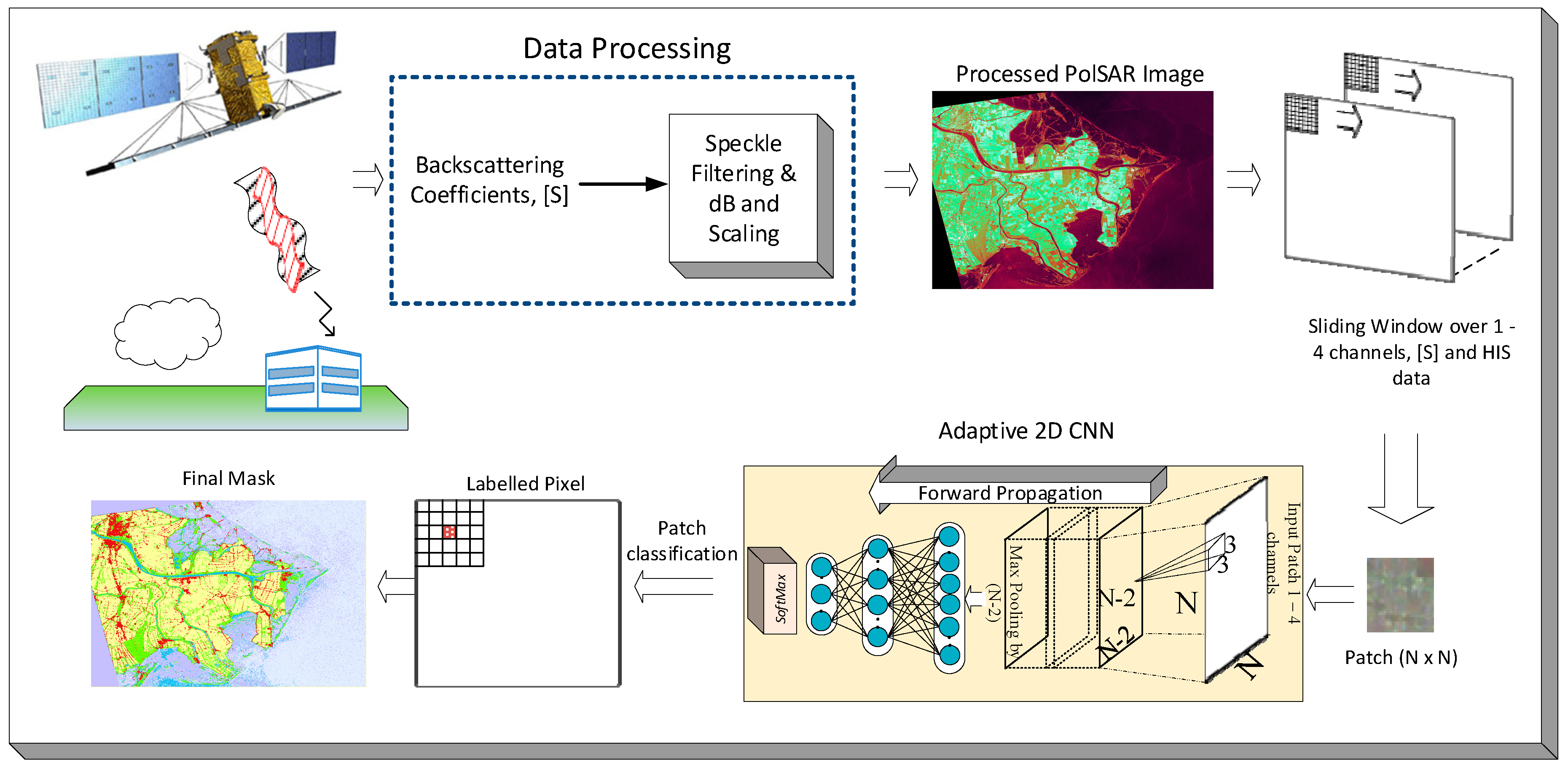
Figure 1. The proposed classification system for single- and dual-polarized Synthetic Aperture Radar (SAR) intensity data.
Remotesensing 11 01340 g001
Figure 2. The proposed Convolutional Neural Network (CNN) configuration as [In-20-10-Out].
Remotesensing 11 01340 g002
Figure 3. Training process of the adaptive 2D CNN by the SAR data.
Remotesensing 11 01340 g003
Figure 4. Pseudo color image of Po Delta SAR image (X-band) is obtained from to HSI (Hue, Saturation, and Intensity) channels and given (left) with its corresponding ground truth set (right) with class labels.
Remotesensing 11 01340 g004
Figure 5. Pseudo color image of Dresden SAR image (X-band) is constructed by assigning backscattering coefficients VV, VV-VH, VV to R, G, and B channels (left) and its corresponding ground truth set is given (right) with class labels.
Remotesensing 11 01340 g005
Figure 6. Learning curve of the proposed Compact CNNs over Po Delta and Dresden SAR data.
Remotesensing 11 01340 g006
Figure 7. Classification performance (recall rates per class) of the proposed and the competing methods for Po Delta data. 11 × 11 and 25 × 25 window sizes are used in the proposed approach with single HH channel, where the competing method in [18] uses HH intensity image and a 208-D composite feature vector with HH, color and texture features (HH + CT).
Remotesensing 11 01340 g007
Figure 8. For Po Delta data, segmentation masks with 11 × 11 window size of one-channel, and 25 × 25 window sizes and of one-, and four-channel(s) are shown in (ac), respectively, using the proposed approach. Their corresponding overlaid regions on the ground truth are shown in (df), respectively.
Remotesensing 11 01340 g008aRemotesensing 11 01340 g008b
Figure 9. Segmentation masks over ground truth of the competing method in [18] using only 72-D Color features in (a), 207-D Color and Texture in (b), and 208-D, HH and Color + Texture in (c) for Po Delta data.
Remotesensing 11 01340 g009
Figure 10. Enlarged regions of ground-truth of Po Delta (a), and corresponding segmentation masks obtained by the competing (b) and the proposed methods (c).
Remotesensing 11 01340 g010
Figure 11. Classification performance (recall rates per class) of the proposed and competing state-of-the-art (soa) methods in [18] for Dresden data. 11 × 11, 15 × 15, and 21 × 21 window sizes are used in the proposed approach with dual (VH/VV) channel, where the competing method uses VH/VV, and a 209-D composite feature vector with VH/VV, and color and texture features (VH/VV + CT).
Remotesensing 11 01340 g011
Figure 12. Segmentation masks of two-channels (VH/VV) with window sizes 11 × 11, 15 × 15, and 21 × 21 shown in (ac), respectively, using the proposed approach over Dresden data. Their corresponding overlaid regions on the ground truth are shown in (df), respectively.
Remotesensing 11 01340 g012aRemotesensing 11 01340 g012b
Figure 13. Segmentation masks of the competing method in [18] using only 72-D Color features in (a), 207-D Color and Texture in (b), and 209-D, VH/VV and Color + Texture in (c) for Dresden data.
Remotesensing 11 01340 g013
Figure 14. Enlarged regions of ground-truth of Dresden (a), and corresponding segmentation masks obtained by the competing (b) and the proposed methods (c).
Remotesensing 11 01340 g014
Table 1. SAR Images used in this work.
NameSystem and BandDateIncident AnglesMode
Po DeltaCOSMO-SkyMed, (X-band)September 200730°Single
DresdenTerraSAR-X, (X-band)Feburary 200841–42°Dual
Table 2. Number of classes, number of samples in training and ground truth (GTD).
NameDimensions# ClassSamples in Training per ClassTotal Samples in GTD
Po Delta 464 × 3156 62000612,000
Dresden 2209 × 3577 61000606,000
Table 3. Classification accuracy of the proposed approach for Po Delta data with different window sizes and number of channels. The obtained highest accuracies are highlighted in bold.
Po Delta (COSMO-SkyMed)1-channel4-channels
Window Size H H H H ,
H u e S a t . I n t .
5 × 50.70980.708
7 × 70.74820.7501
9 × 90.76980.7668
11 × 110.7890.7838
13 × 130.80750.8037
15 × 150.81470.8167
17 × 170.82760.83
19 × 190.83870.8442
21 × 210.84040.8537
23 × 230.8480.8539
25 × 250.84870.8632
27 × 270.85330.8615
Table 4. Confusion matrix over Po Delta data obtained by the proposed approach using the best setup with window size 25 and four channels (HH - Hue-Sat.-Int.). The number of correctly classified samples per class and in total are highlighted in bold.
Predicted
UrbanInWaterForestWetlandWaterCropTotal
TrueUrban92,26460713225405753100,000
InWater93185,3083824678112101946100,000
Forest934258190,5079091864883100,000
Wetland1666153115780,68311,74497100,000
MaWater48219616617,50280,06721100,000
Crop4680105548752535289,085100,000
Total99,02397,900101,851106,18293,259101,785517,914
Table 5. Classification accuracies of the proposed approach for Dresden data with different window sizes. The highest accuracy (highlighted in bold) is obtained with 21 × 21 window size.
Dresden
(TerraSAR-X)
2-channel
Window Size V H / V V Window Size V H / V V
5 × 50.705917 × 1780.07
7 × 70.750919 × 190.8105
9 × 90.765421 × 210.8133
11 × 110.779723 × 230.8029
13 × 130.789825 × 250.8092
15 × 150.79827 × 270.8062
Table 6. Confusion matrix over Dresden data obtained by the proposed approach using the best setup with window size 21 and two channels (VH/VV). The number of correctly classified samples per class and in total are highlighted in bold.
Predicted
UrbanIndustrialInWaterForestPasturesCropTotal
TrueUrban73,40918,980169332317752344100,000
Industrial16,49278,87017210034153048100,000
InWater1474119293,01219552182185100,000
Forest3081118985590,71221931970100,000
Pastures39611199977386373,17516,825100,000
Crop28951035113133715,80278,818100,000
Total101,312102,46595,298102,19395,542103,190487,996
Table 7. Classification accuracies of Xception, Inception-Resnet-v2, and the proposed compact CNN over Po Delta data using four-channels ( H H ,   H u e ,   S a t . ,   I n t . ) with different window sizes. Layers of Xception* and Inception-ResNet-v2* (except MLP part and the first convolution layer) are initialized with ImageNet weights. The obtained highest classification accuracies are highlighted in bold for different window sizes.
Window Size Xception Xception*Inception ResNet-v2Inception ResNet-v2*Proposed
5 × 50.66880.69630.68620.69280.708
11 × 110.75630.77360.76080.76560.7838
17 × 170.78960.79430.80320.81210.83
25 × 250.84450.84350.85550.84470.8632
Table 8. Classification accuracies of Xception, Inception-Resnet-v2, and the proposed compact CNN over Dresden data using 2-channels ( V H V V ) with different window sizes. Layers of Xception* and Inception-ResNet-v2* (except MLP part and the first convolution layer) are initialized with ImageNet weights. The obtained highest classification accuracies are highlighted in bold for different window sizes.
Window SizeXceptionXception*Inception ResNet-v2Inception ResNet-v2*Proposed
5 × 50.46370.50040.46570.47540.7059
11 × 110.64810.68360.65560.64880.7797
17 × 170.73420.75960.74410.74590.8007
21 × 210.77060.77830.77670.77960.8133
27 × 270.79600.80680.81160.80640.8062
Table 9. Performances of each class in terms of Precision, Recall and F1 Score of Xception, Inception-Resnet-v2, and the proposed approach over Po Delta data using the best setup with window size 25 and using four channels (HH - Hue-Sat.-Int.). The obtained highest classification performances in terms of each metric are highlighted in bold for each class.
Po Delta
(Classes)
Precision
Xcep.  Inc. Res2.  Prop.
Recall
Xcep.  Inc. Res2.  Prop.
F1 Score
Xcep.  Inc. Res2.  Prop.
Urban0.96170.72460.93170.96310.73410.92260.96240.72930.9272
InWater0.80910.76970.87140.89070.78870.85310.84790.77910.8621
Forest0.9020.97600.88860.92440.93010.90510.91310.95250.8968
Wetland0.70140.88770.75990.69560.90710.80680.69850.89730.7826
MaWater0.79030.76590.85850.70530.73180.80070.74540.74840.8286
Araple Land0.89390.76380.87520.88380.78820.89090.88880.77580.8830
Table 10. Performances of each class in terms of Precision, Recall and F1 Score of Xception, Inception-Resnet-v2, and the proposed approach over Dresden data using the best setup with window size 21 and using two channels ( V H / V V ). The obtained highest classification performances in terms of each metric are highlighted in bold for each class.
Dresden
(Classes)
Precision
Xcep  Inc. Res2.  Prop.
Recall
Xcep.  Inc. Res2.  Prop.
F1 Score
Xcep.  Inc. Res2.  Prop.
Urban0.63870.68750.72460.61440.58830.73410.62630.63410.7293
Industrial0.71160.71360.76970.66080.73490.78870.68520.72410.7791
InWater0.9990.99950.97600.9650.97430.93010.98170.98670.9525
Forest0.84120.84260.88770.90220.90670.90710.87060.87350.8973
Pastures0.7910.80250.76590.79330.82590.73180.79210.81410.7484
Araple Land0.78680.81120.76380.84040.83910.78820.81270.82490.7758
Table 11. The classification performance comparison of the proposed approach with Xception and Inception-Resnet-v2 based on Cohen’s kappa coefficient (κ) over Po Delta and Dresden data, using window size 25 and 27 with four channels (HH - Hue-Sat.-Int.) and two channels ( V H / V V ), respectively. The obtained largest kappa coefficients are highlighted in bold for Po Delta and Dresden data.
SAR DataXceptionInception ResNet-v2Proposed
Po Delta0.72030.72780.7369
Dresden0.68280.69500.6986
Table 12. Classification accuracy results of the eight network configurations with different number of hidden neurons (multiplier m) and hidden CNN layers (multiplier n), where m = n = 1 stands for the default configuration. The highest accuracy is obtained with m = 4, n = 1 as highlighted in bold.
Po Delta (HH)Dresden
(VH/VV)
m = 1, n = 10.84870.8133
m = 1, n = 20.80150.7772
m = 2, n = 10.84930.8176
m = 2, n = 20.79450.7747
m = 4, n = 10.86830.8371
m = 4, n = 20.79080.7766