Initial Positioning Assessment of BDS New Satellites and New Signals


1
Tokyo University of Marine Science and Technology, Tokyo 1358533, Japan
2
Shanghai Key Laboratory of Space Navigation and Positioning Techniques, Shanghai 200030, China
3
Shanghai Astronomical Observatory, Shanghai 200030, China
4
College of Surveying and Geo-Informatics, Tongji University, Shanghai 200092, China
5
Chinese Academy of Surveying and Mapping, Beijing 100830, China
*
Authors to whom correspondence should be addressed.
Remote Sens. 2019, 11(11), 1320; https://doi.org/10.3390/rs11111320
Submission received: 9 May 2019
/
Revised: 27 May 2019
/
Accepted: 29 May 2019
/
Published: 1 June 2019
(This article belongs to the Special Issue High-precision GNSS: Methods, Open Problems and Geoscience Applications)
Abstract
:With the official announcement of open service since the end of 2018, the BeiDou navigation satellite system (BDS) has started to provide global positioning, navigation and timing (PNT) services. Thus, it is worth assessing the positioning service of new BDS satellites and signals. In this paper, we comprehensively assess the system status and the global positioning performance of BDS regarding single point positioning (SPP) and real-time kinematic (RTK) performance. Results show that the signal in space range error (SISRE) of BDS-3 satellites is superior to that of BDS-2 satellites, showing an overall accuracy of 0.71 m versus 0.97 m, which is competitive with GPS and Galileo. With the contribution of BDS-3, the number of global average visible satellites has increased from 5.1 to 10.7, which provides a mean global position dilution of precision (PDOP) value better than 6 at 99.88% and the mean availability of basic PNT performance is also improved from 35.25% to 98.84%. One week of statistical results from 54 globally distributed international GNSS service (IGS) stations show that the root mean square (RMS) of SPP accuracy is 1.1 m in horizontal and 2.2 m in vertical, which is at the same level of GPS. The new B1c and B2a signals show a smaller observation noise than B1I, and SPP performance of B1c is similar to that of B1I. However, the positioning precision is slightly worse at the B2a frequency, which may be due to the inaccurate BDS ionosphere correction. As for short baseline RTK, baseline accuracy is also improved due to the increased number of new BDS satellites.

1. Introduction
The second phase of the BeiDou navigation satellite system space segment (BDS-2) consists of Geosynchronous Earth Orbit (GEO), Inclined Geosynchronous Orbit (IGSO) and Medium Earth Orbit (MEO) satellites and it started to provide regional service around the Asia-Pacific area, namely from 55°S to 55°N latitude and 55°E to 180°E longitude, since the end of 2012 [1]. BDS-2 aims to provide a better than 10 m (probability of 95%) positioning accuracy in horizontal and vertical, and timing precision better than 50 ns within the service area [2]. The performance of the BDS-2 system has been fully investigated by many researchers in the aspects of precise orbit determination (POD), observation noise, multipath, positioning performance including single point positioning (SPP), precise point positioning (PPP) and real-time kinematic (RTK) and so on [3,4,5,6,7].
Since 2015, China began to develop BDS-3 aiming to provide a global service. Five experimental satellites were launched for demonstration purposes during the period from 2015 to 2016. More BDS-3 satellites have been launched since 2017. Currently, the BDS system constellation consists of five GEO, seven IGSO and 21 MEO satellites, which includes 15 BDS-2 satellites and 18 BDS-3 satellites [8]. By the end of 2018, BDS was announced to be providing a global positioning, navigation and timing (PNT) service, which supports positioning accuracy of 10 m (95%) in horizontal and vertical throughout its global coverage, and timing accuracy better than 20 ns. By the end of 2020, the full BDS constellation will be completed with the continuous launching of additional BDS-3 satellites. The BDS signal in space range error (SISRE) will be better than 0.5 m with higher stability. Additionally BDS will provide a satellite-based augmentation service around China, an international search and rescue service, and a precise point positioning service [9].
Compared with BDS-2, the BDS-3 satellites show differences in three aspects: (1) in addition to B1I and B3I signals, BDS-3 satellites also transmit signals B1c and B2a, which are centralized at the same frequency as L1(GPS)/E1(Galileo) and L5(GPS)/E5a(Galileo), making BDS compatible with and interoperable with GPS and Galileo [8,10]; (2) BDS-3 satellites are equipped with inter-satellite link (ISL) payloads in the Ka band which enable autonomous navigation and with ISL range measurements with accuracy less than 10 cm, the orbit overlap difference would be between 10 and 20 cm [11,12,13]; (3) BDS-3 employs a new generation of high-precision rubidium (Rb) clocks and passive hydrogen maser (PHM) clocks, which indicate a lower frequency drift than BDS-2. The frequency stability of the PHM clock shows about 6 × 10⁻¹⁵ at an interval time of 1-day [14].
Current research mainly focuses on the space segment of the new BDS-3 satellites. With the implementation of the BDS-3 service, it is of great significance to investigate the positioning performance of the current BDS constellation. Zhang et al. [15] analyzed the benefit of BDS-3 experimental (BDS-3e) satellites, and indicate that BDS-3e satellites no longer suffer from satellite-induced elevation dependent code bias which was first discovered by Wanninger and Beer [5]. Meanwhile, B2a has a smaller code multipath and BDS-3e satellites would improve ambiguity resolution performance in RTK. Zhang et al. [16] further proved that with the help of BDS-3e satellites, the convergence time of PPP would also shorten for areas with fewer visible satellites. Yang et al. [17] assessed the user equivalent range error (UERE) of BDS-3e, which is smaller than 0.73 m and the timing accuracy is usually better than 10 ns. To assess the possible positioning and navigation accuracy, a simulated BDS-3 constellation consisting of three GEO, three IGSO, and 24 MEO satellites was also designed to predict the dilution of precision (DOP) value of the final BDS-3 constellation [17,18]. In 2019, Yang et al. [19] first gave a 4-day SISRE result of eight BDS-3 satellites comparing broadcast ephemeris and POD results from International GNSS Monitoring and Assessment System (iGMAS), which shows that the root mean square (RMS) error of the satellite orbit in three-dimensions (3D) is about 1.07 m, while the average RMS of the satellite clock error is 1.12 ns and the average SISRE is 0.44 m. However, there is still little research on positioning performance using the current BDS-2 and BDS-3 constellation.
This paper aims to present an initial assessment of the positioning performance of the current BDS constellation with new satellites and new signals. Section 2 investigates the global satellite visibility and position dilution of precision (PDOP) of the current BDS constellation. To verify the accuracy of the satellite segment, Section 3 presents the SISRE of BDS with over 60 days of data. Then, in Section 4 we assess the SPP performance of BDS using 54 globally distributed stations which is also compared with that of the GPS and BDS-2 systems. Positioning performance of the new BDS signals including B1c and B2a is also analyzed and compared. In Section 5, RTK performance of the current BDS is assessed in comparison with the BDS-2 system. Finally, conclusions are presented.
2. Satellite Visibility and PDOP Availability
With the availability of BDS-3 satellites, global users would benefit from the PNT service from BDS as more satellites are visible all over the world. To investigate the service area with the current BDS constellation, we will assess the satellite visibility, PDOP value and availability in this part.
Using the broadcast ephemeris on 1 January 2019, we explore the global satellite visibility and PDOP value comparing BDS-2 and the current constellation of BDS-2 and BDS-3. The latitude and longitude are divided into a 2° × 2° grid and the satellite elevation mask is set as 10°. As for PDOP, we adopt the conventional concept that a PDOP value less than 6 is necessary to provide basic PNT service [8]. To assess the normal performance, the result is calculated on an hourly basis and the global average result is plotted, which is depicted in Figure 1 and Figure 2, and the minimum, maximum and average satellite number are listed in Table 1.
It can be observed from Figure 1 and Table 1 that for BDS-2 constellation, the maximum visible satellite number is about 13.8, which is located in Southeast Asia, where the equatorial region is at the longitude of about 110°. For the opposite part of the Earth, i.e., the Americas, the average satellite number would less than 4, which is challenging for PNT service. With the contribution of BDS-3 satellites, Southeast Asia would still be the “hottest” area of BDS, with 20 satellites that can be tracked at most. As for the Americas, a minimum number of 5.7 satellites is visible, which indicates that a global PNT service is possible using the current BDS-2 and BDS-3 constellation. Comparing with BDS-2, the global average visible satellite number increases from 5.1 to 10.7.
As for PDOP, it shows a similar performance. For BDS-2, the minimum PDOP is 1.8, while for BDS-2+BDS-3, it would decrease to 1.2. Outside the Asia-Pacific region, PDOP of BDS-2 would dramatically increase. Nevertheless, combining BDS-2 and BDS-3, the PDOP value changes gradually and it is still able to provide normal PNT service in the Americas, with a maximum PDOP value of 3.3.
For the above PDOP statistics, only values of less than 6 are counted. However, for a navigation system, the percentage of time to provide a specified level of PNT service, or the availability, is also important [20]. For the case of BDS-2 PDOP performance, although some areas outside the Asia-Pacific region could experience normal PDOP, most of the time the PDOP is larger than 6, which is not shown in Figure 2. Therefore, it is necessary to assess PDOP availability.
In this paper, we define the PDOP availability as the percentage of time that the PDOP value is less than 6 [8]. Figure 3 plots the global overall PDOP availability of BDS-2 and BDS-2+BDS-3 constellation and the minimum, maximum and average value are listed in Table 1. It can be seen that for BDS-2, the average of global PDOP availability is only 35.25%, which is mostly around the Asia-Pacific region, while for BDS-2+BDS-3, it could reach the level of 98.84%, which fulfills the target of PDOP availability of BDS open service performance standard [8].
3. Signal in Space Range Error
For real-time PNT services such as SPP or RTK, the precision of broadcast ephemeris is a key factor. SISRE is a common quantity used to assess the quality of broadcast ephemeris [21]. SISRE of BDS-2 has been assessed by many researchers [21,22,23,24]. It is reported that the SISRE of BDS-2 is about 1 m [24]. As for BDS-3, Yang et al. [19] showed that the average SISRE is 0.44 m using eight BDS-3 satellites. To investigate the overall performance, the SISRE of the current BDS constellation is explored in this section.
SISRE of broadcast ephemeris is usually compared with precise orbit and clock products. Precise BDS-3 products of Wuhan University (WUM) [25] are used here. Although no exact precision of the WUM products is reported for BDS-3 satellites, previous research indicates that the average 3D orbit RMS is better than 20 cm [11,12,13], as there are still not many stations tracking BDS-3 satellites. Comparing with the 0.5–1.0 m level precision of broadcast ephemeris, WUM products would be sufficient to assess the SISRE of BDS broadcast ephemeris.
When comparing BDS broadcast ephemeris with WUM final products, difference such as time and coordinate system should be considered [21]. Besides, we should also consider the following corrections:
- (1)
- Satellite antenna offset correction. Starting from 7 January 2017, BDS changed the orbit reference point from the center of mass (CoM) to the antenna phase center (APC) [26], which is the same as other GNSS systems. For precise orbit and clock products, it is referred to the CoM. Such differences should be corrected when comparing orbit difference. The antenna phase center offset (PCO) used in broadcast ephemeris is provided by the Test and Assessment Research Center of China Satellite Navigation Office (TARC-CSNO). According to Guo [25], for WUM products, the PCO value of BDS-3 are also provided by TARC-CSNO, while PCO of BDS-2 are estimated by Wuhan University [27]. Therefore, the inconsistency that affect the radial component should be corrected for BDS-2 satellites, while a zero offset can be adopted for BDS-3 satellites.
- (2)
- Clock and TGD/DCB correction. It is known that there exists a system bias among different products. Commonly an ensemble clock offset is computed at each epoch from the average broadcast-minus-precise clock values of satellites [21]. To reduce the effect of gross errors from some satellites, we use a medium value of broadcast-minus-precise clock as the offset [22].Meanwhile, the satellite clock in the BDS broadcast ephemeris is referred to the B3I signal [1], while for WUM products, it is referred to the ionosphere-free combination of B1I/B3I signals instead of the traditional B1/B2 signals [25]. This kind of difference between B3I and B1I/B3I should be corrected by the timing group delay (TGD) [28]. Similar to TGD but with a higher precision, differential code bias (DCB) of the BDS is also provided by the Chinese Academy of Science (CAS) [29].
A common method to calculate SISRE can be expressed as:
where R, A, C stand for the orbit error in radial, along-track and cross-track direction, Clk means the clock error, α and β are the weighting factors for the line of sight. A detailed value can be found in [21].
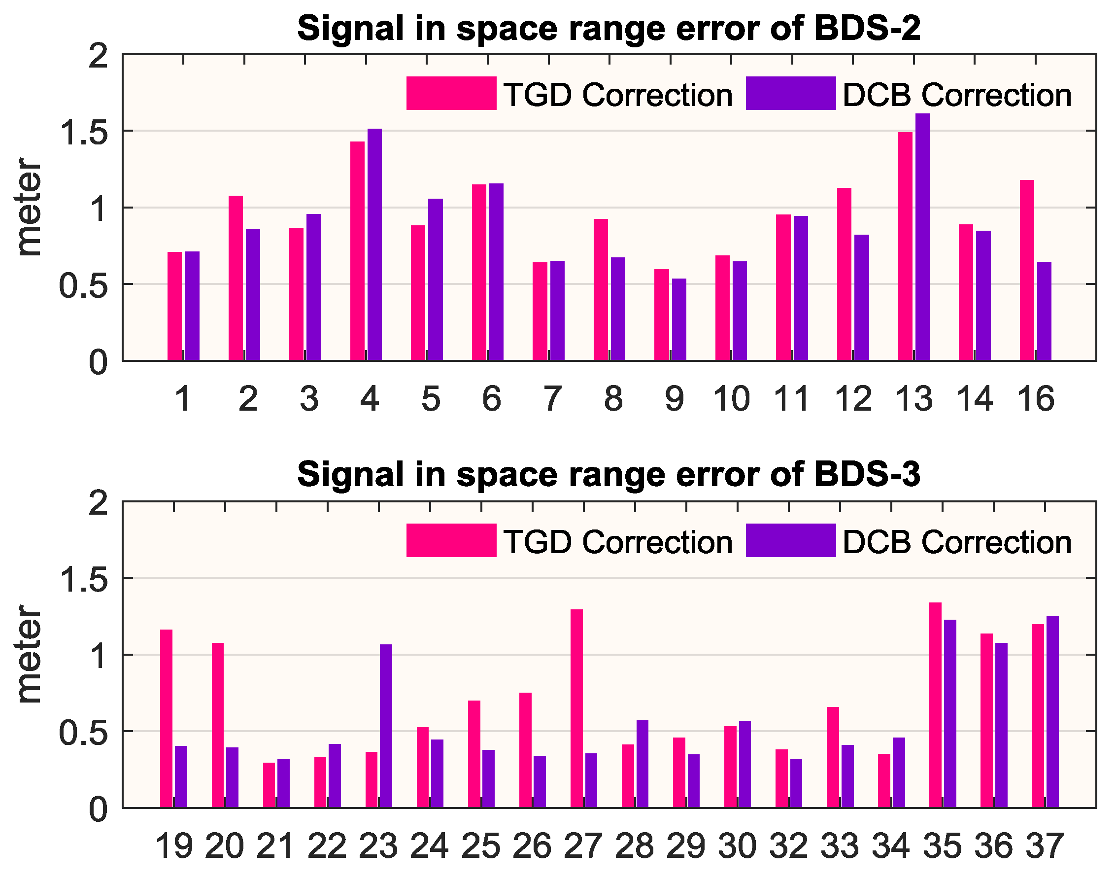
We take two months of data from day of year (DOY) 10 to DOY 70, 2019 for assessment. For comparison, TGD and DCB are applied respectively. The data sampling is set as 10 min and the threshold of gross outlier rejection is set as 10 m. The SISRE statistics for BDS-2 and BDS-3 are listed in Table 2, and the statistical RMS of SISRE for each satellite is plotted in Figure 4.
From Table 2 we can see that the overall SISRE of the current BDS constellation is 0.83 m (TGD correction) or 0.71 m (DCB correction). For BDS-2, the SISRE is within 1 m, which shows a similar performance as reported in Montenbruck et al. [24]. For BDS-3, with the contribution of a more stable satellite clock and a new ISL technique, SISRE of BDS-3 is superior to BDS-2, where the average SISRE is 0.71 m versus 0.96 m after TGD correction. If DCB correction is applied, the average SISRE is 0.57 m versus 0.90 m, respectively, which indicates that the TGD accuracy of BDS-2 is similar to DCB, while the TGD accuracy for BDS-3 is slightly worse. As it can be seen from the lower subplot of Figure 4, some satellites show an obvious poor SISRE after TGD correction. This may be due to the accuracy of the TGD on these satellites. Meanwhile, it is interesting that the SISRE of C35-C37 are apparently worse than other BDS-3 satellites. As reported by Deng [30], receivers able to track C35~C37 are much less than other BDS-3 satellites, which would lead to lower accuracy of precise orbit and clocks for C35-C37. If C35-C37 are excluded, SISRE of BDS-3 would reduce to 0.62 m (TGD correction) or 0.45 m (DCB correction), which is at the similar level of GPS and Galileo.
4. SPP Performance
PDOP availability analyzed in the previous section shows that a global BDS PNT service is available with a mean percentage of 98.84%. In this section, we will explore the SPP performance.
4.1. Data Setup and Processing Strategy
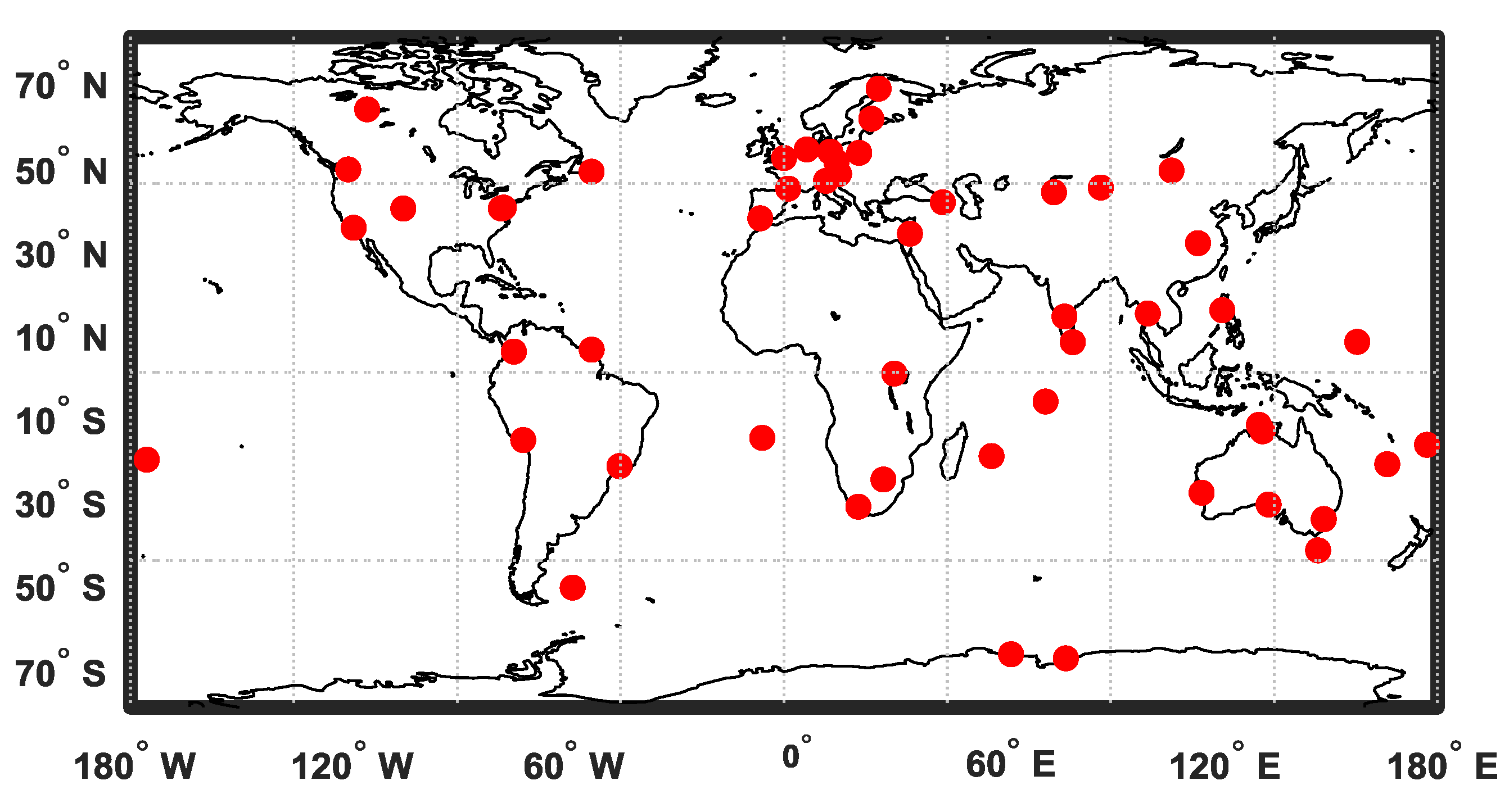
As a volunteer association, the International GNSS Service (IGS) continuously provides multi-GNSS data and products [31]. For the validation of positioning, 54 globally distributed IGS stations are selected, as shown in Figure 5. These stations are equipped with JAVAD or SEPTENTRIO receivers, which are able to receive BDS signals B1I, B2I and B3I. Among JAVAD receivers, some firmware versions of JAVAD TRE_3 and JAVAD TRE_3 DELTA are able to receive new B1c and B2a BDS signals.
For a statistical result, one-week of data at a sampling of 30 s from DOY 13 to 19 in 2019 are collected at these stations. For the processing of SPP, broadcast orbits and clocks are used. As the BDS broadcast clock refers to B3 frequency, TGD should be corrected when observations of other frequencies or frequency combinations are used. The cut-off elevation is set as 10°, and observations with a PDOP value higher than 6 are rejected. Troposphere delay is corrected by GPT2w and the VMF model [32], ionosphere delay is corrected by the broadcast model. Hence, the estimated parameters are station coordinates and the receiver clock.
The stochastic model of the observations in SPP is composed by:
where σ is the variance of code observation, while σSISRE, σTrop, σIono, σCode stand for the SISRE of satellites, troposphere error after model correction, ionosphere error after model correction and code measurement noise, respectively.
According to the analysis of SISRE in the previous section, σSISRE can be set as 1.0 m for BDS-2 satellites and 0.7 m for BDS-3 satellites. As for σTrop, it can be described by:
where σTrop_Z is the zenith accuracy of the troposphere model and mfTrop is a troposphere mapping function. According to Böhm et al. [32], the accuracy of the zenith GPT2w model is at about 0.05 m.
Similarly, σIono can be expressed as:
where σIono_V is the vertical precision of the ionosphere model correction and mfIono is the mapping function at the pierce point.
σCode is determined by an elevation dependent model [33]:
where Ele is the satellite elevation and σ0 is the measurement noise of pseudo-range, which is set as 0.3 m.
4.2. SPP Performance with Current BDS Constellation
Applying the least squares method, station coordinates are estimated in a kinematic way at each epoch. For comparison, the estimated coordinates are then compared with precise reference coordinates provided by the IGS final solutions in daily SINEX files.
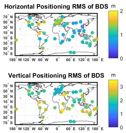
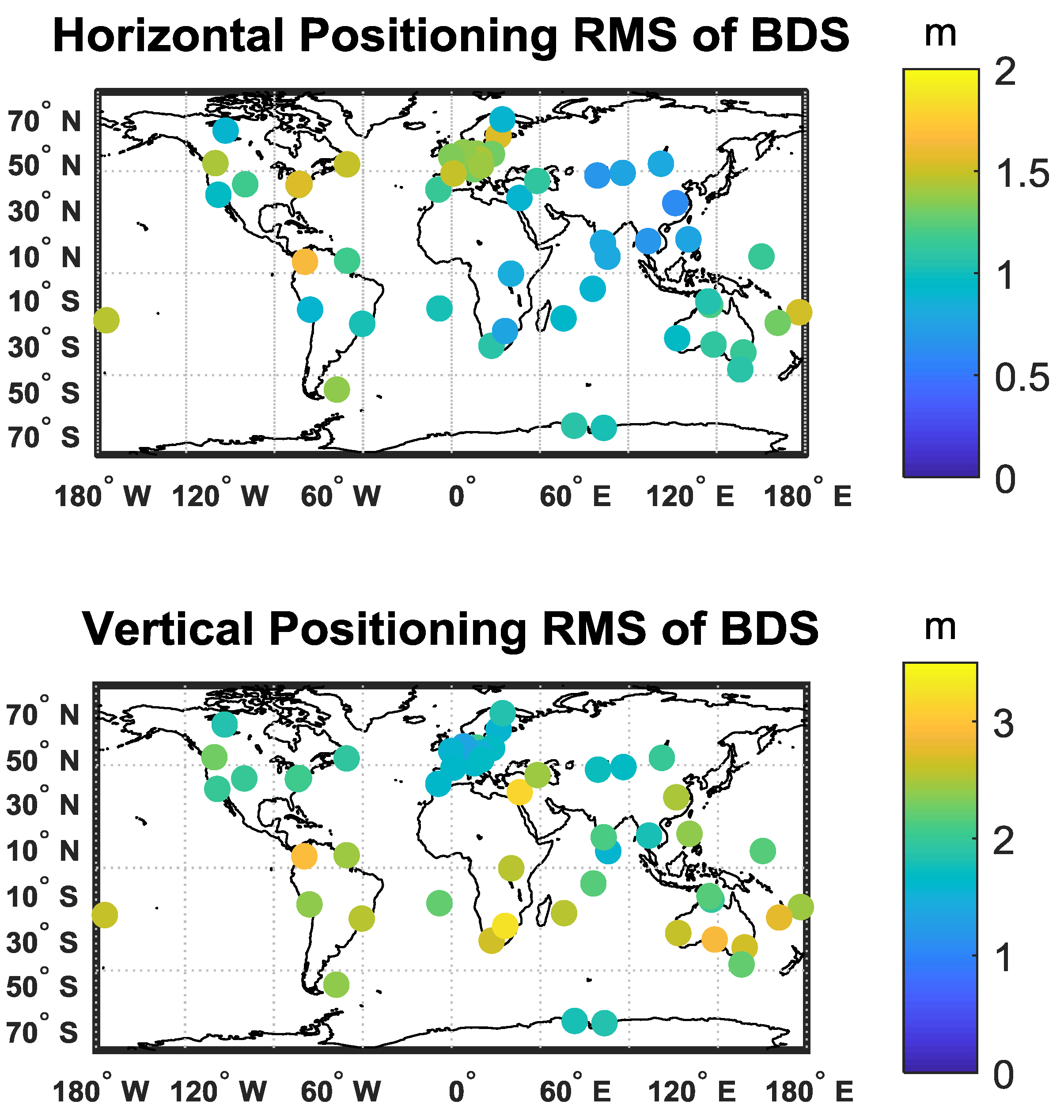
The B1I signal is used for single frequency SPP as it is available for all satellites at all stations. To fully evaluate the performance of BDS, we also assess SPP performance of GPS using data at the L1 frequency. The overall average 7-day RMS and 95% accumulated error of 54 stations are summarized in Table 3, and the average 7-day RMS in the horizontal and vertical component of each station is plotted in Figure 6.
From Table 3 we can conclude that current BDS can provide a global positioning accuracy of 1.1 m and 2.2 m in horizontal and vertical, respectively. For the 95% accumulated error, it is at 2.2 m and 3.9 m in horizontal and vertical, which meets the BDS positioning accuracy standard goal [8]. Accordingly, the positioning performance of BDS shows a competitive performance when compared with GPS. The horizontal error of BDS seems slightly worse than GPS in RMS and 95% probability, while vertical error is almost at the same level.
It can be observed from Figure 6 that the horizontal RMS is well below 1 m in the Asia-Pacific region, while it would be worse than 1 m around the Americas, which is consistent with the PDOP performance. However, it is interesting to find that the vertical RMS in the Southern Hemisphere is worse than the Northern Hemisphere in general. This may result from the inaccurate model of ionosphere correction in the Southern Hemisphere, which needs further analysis.
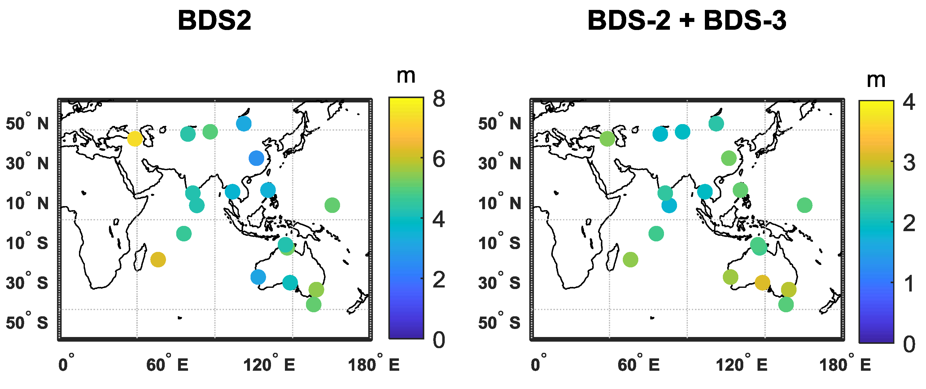
To investigate the benefit of BDS-3, 20 out of 54 stations around the Asia-Pacific and Indian Ocean region are selected and compared with BDS-2-only SPP performance. An average of 7-day 3D RMS results for BDS-2-only and BDS-2+BDS-3 are illustrated in Figure 7. A statistical result in RMS and 95% accumulated error are listed in Table 4. It is obvious to see the advantage of BDS-3 in improving horizontal and vertical accuracy. Comparing with global performance in Table 3, the horizontal accuracy is slightly better in the service area of BDS-2, as more satellites are visible. As BDS-2 performance decreases dramatically beyond the center of the Asia-Pacific region, the contribution of BDS-3 would be more obvious in these regions. What is more, it is interesting to find that for the BDS-2-only case, the positioning accuracy in the North-South component is better than the East-West component, while it is opposite for the BDS-2+BDS-3 or GPS case. This may be due to the reason that 5 GEO satellites of the BDS-2 are located over the equator at longitude of 58.75°E, 80°E, 110.5°E, 140°E and 160°E respectively, which would contribute to the DOP value in the North-East component. When BDS-3 satellites are included with a better SISRE, this kind of GEO contribution would decrease.
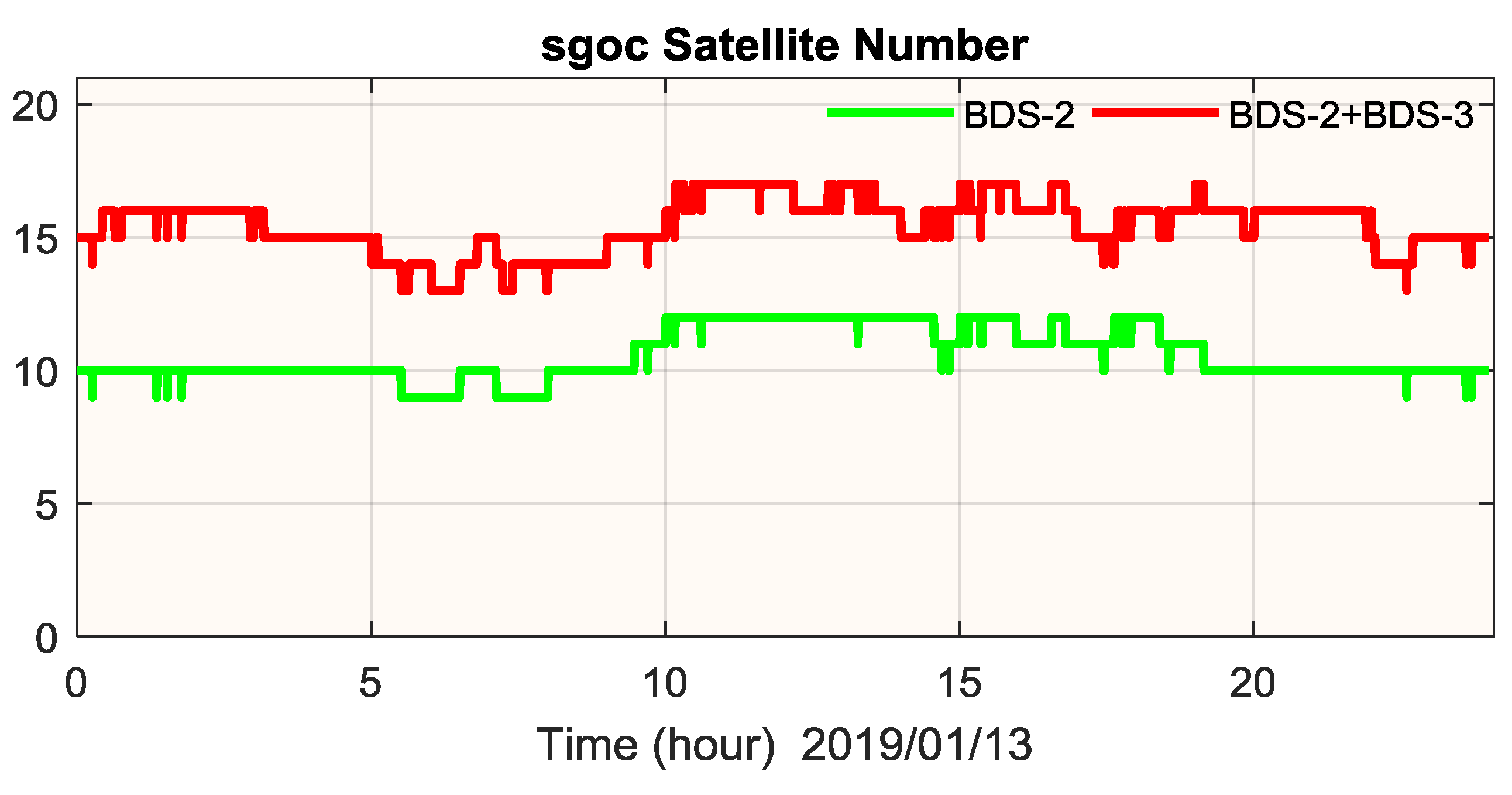
Furthermore, to have a specific observation of the contribution of BDS-3, we take one of the stations, SGOC (6.89°N, 79.87°E) as an example. Figure 8 depicts the visible satellite number on January 13, 2019. The average satellite number increases from 10.6 to 15.5 with the help of BDS-3, which would definitely contribute to positioning performance. The corresponding RMS of the SPP result, as shown in Figure 9, would improve from [0.93 m, 1.35 m, 1.82 m] to [0.69 m, 1.11 m, 1.68 m] in the North-East-Up component with a smaller positioning noise due to better PDOP and smaller SISRE of the BDS-3 satellites.
4.3. New Signal of B1c and B2a
The positioning results in the previous sub-section are based on B1I signal. In this subsection, we will investigate the SPP performance using the new BDS signals B1c and B2a. Due to the data limitations, only nine out of 54 IGS stations are able to receive the B2a signal, and only four stations are able to receive the B1c signal. As B1c and B2a signals are only transmitted by BDS-3 satellites, for a better comparison, only data of BDS-3 satellites are used in this section. Similar with previous analysis, an average of 7-days of SPP RMS and 95% accumulated error on B1I, B1c and B2a are presented in Table 5, and the RMS of SPP results at each station are plotted in Figure 10. When comparing the different frequencies, one can see that SPP accuracy on B1I and B1c frequency is at a similar level. It seems that horizontal error on the B1I frequency is slightly better than B1c, while B1c shows slightly better performance in the vertical. For the B2a frequency, it presents a much worse result than the B1I or B1c frequency, which may possibly be attributed to the inaccurate ionosphere correction on B2a.
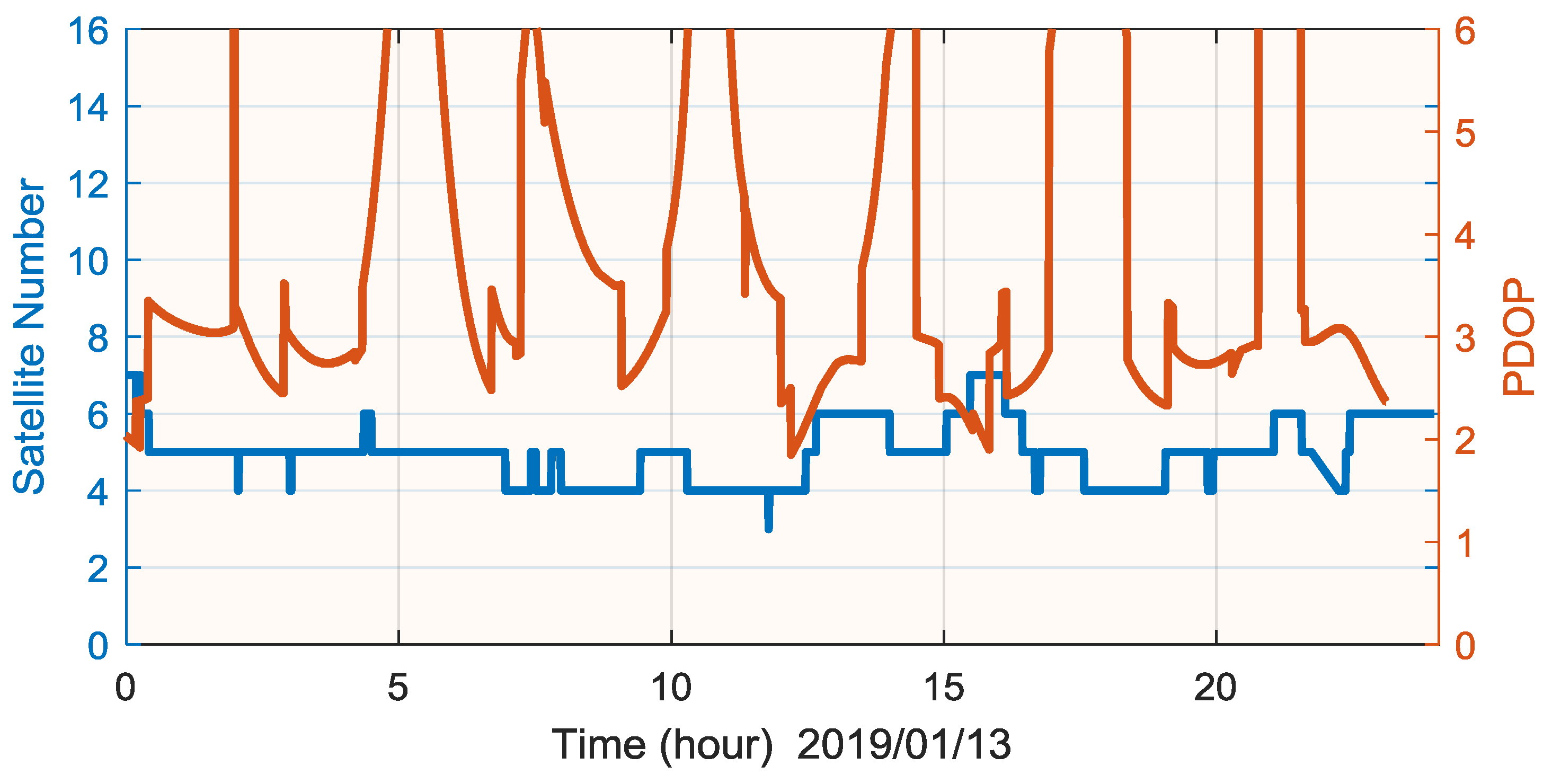
To investigate the detailed positioning performance of new signals, we choose the station of BSHM (32.78°N, 35.02°E) for analysis. Figure 11 depicts the satellite number and PDOP value of BDS-3 on 13 January 2019. As we can see, the number of visible satellites for BDS-3 at station BSHM is between 4 and 7. With a PDOP threshold of 6, the positioning availability is about 79.3%.
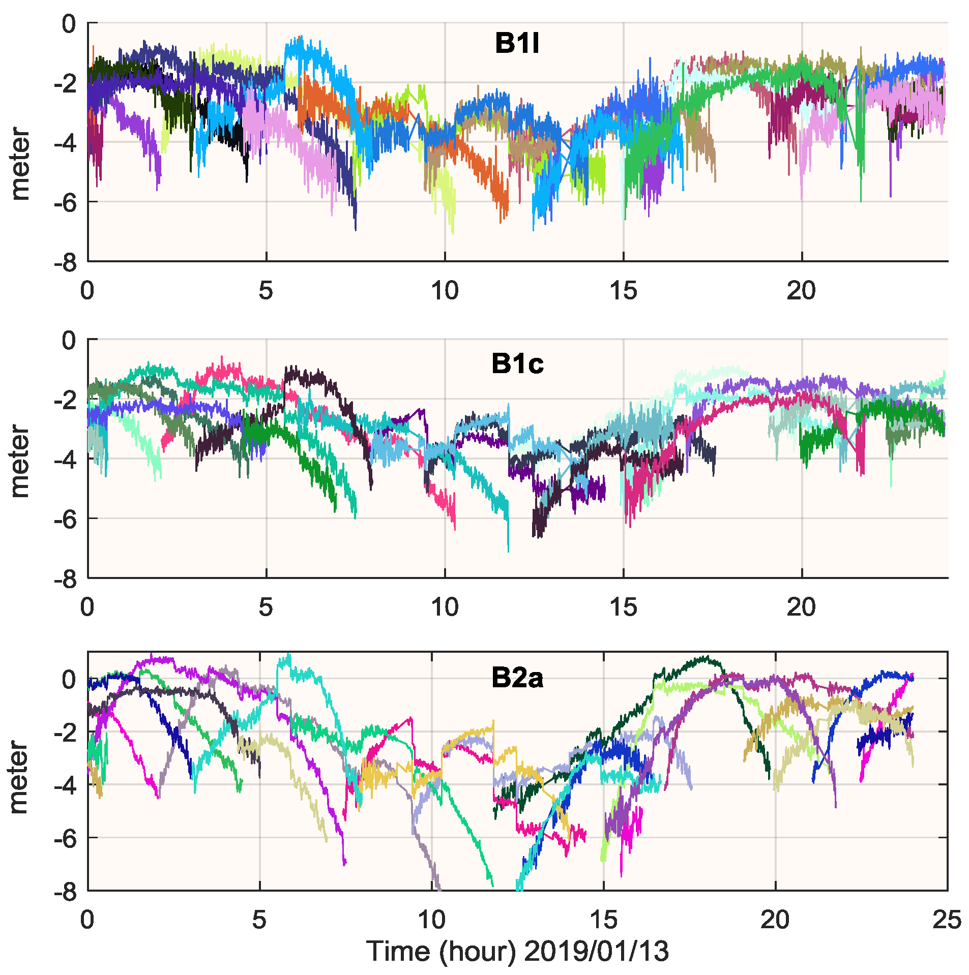
Daily SPP performance of B1I, B1c and B2a at station BSHM are evaluated, as shown in Figure 12. Similar conclusion can be found that B1I and B1c performs a similar positioning accuracy, while it is much worse on B2a. Furthermore, it seems that positioning error dispersion on B1I is much noisier than B1c and B2a. To validate it, the pre-fit observation minus corrections (OMC) of B1I, B1c and B2a are calculated using true coordinates, which are illustrated in Figure 13. Obviously, the OMC noise on B1c and B2a is much smaller than B1I. This is different from the BDS-3e satellite, whose B1c noise is at the same level as B1I [15]. However, although the B2a signal performs the smallest noise, the OMC on B2a shows a much more dispersive residual, thus resulting in the worst positioning error. This may be due to the inaccurate model of ionosphere correction, which has a more serious impact on B2a rather than B1I or B1c.
5. RTK Performance
In this section, we evaluate the RTK performance using the current BDS constellation. Two baselines at different lengths are selected. One is a 20 m baseline from station YARR to YAR3 (29.05°S, 115.35°E), the other is a 10 km baseline from station STR1 to TID1 (35.40°S, 148.98°E). Data on January 1, 2019 is selected for the RTK assessment of the two baselines.
For the RTK strategy, dual-frequency data on B1I and B3I are used. Conventional continuous mode without considering troposphere and ionosphere difference is applied during ambiguity resolution (AR). To reduce the impact of noise from low elevation satellites, the cut-off elevation is set as 10° for float solution in Kalman Filter and 20° in the procedure of ambiguity fixing. A threshold of 3.0 with a success rate of 0.99 is set for ratio test in LAMBDA method [34]. In the case of AR, ambiguity dilution of precision (ADOP) is an important concept indicating the success rate of AR. According to Teunissen [35], ADOP can be defined as:
where is the variance-covariance matrix of float ambiguities and |·| is the determinant of the matrix, n is the dimension of the ambiguity vector. As pointed out by Odijk and Teunissen [36], if ADOP is smaller than 0.14 cycle, the AR success rate would better than 0.99.
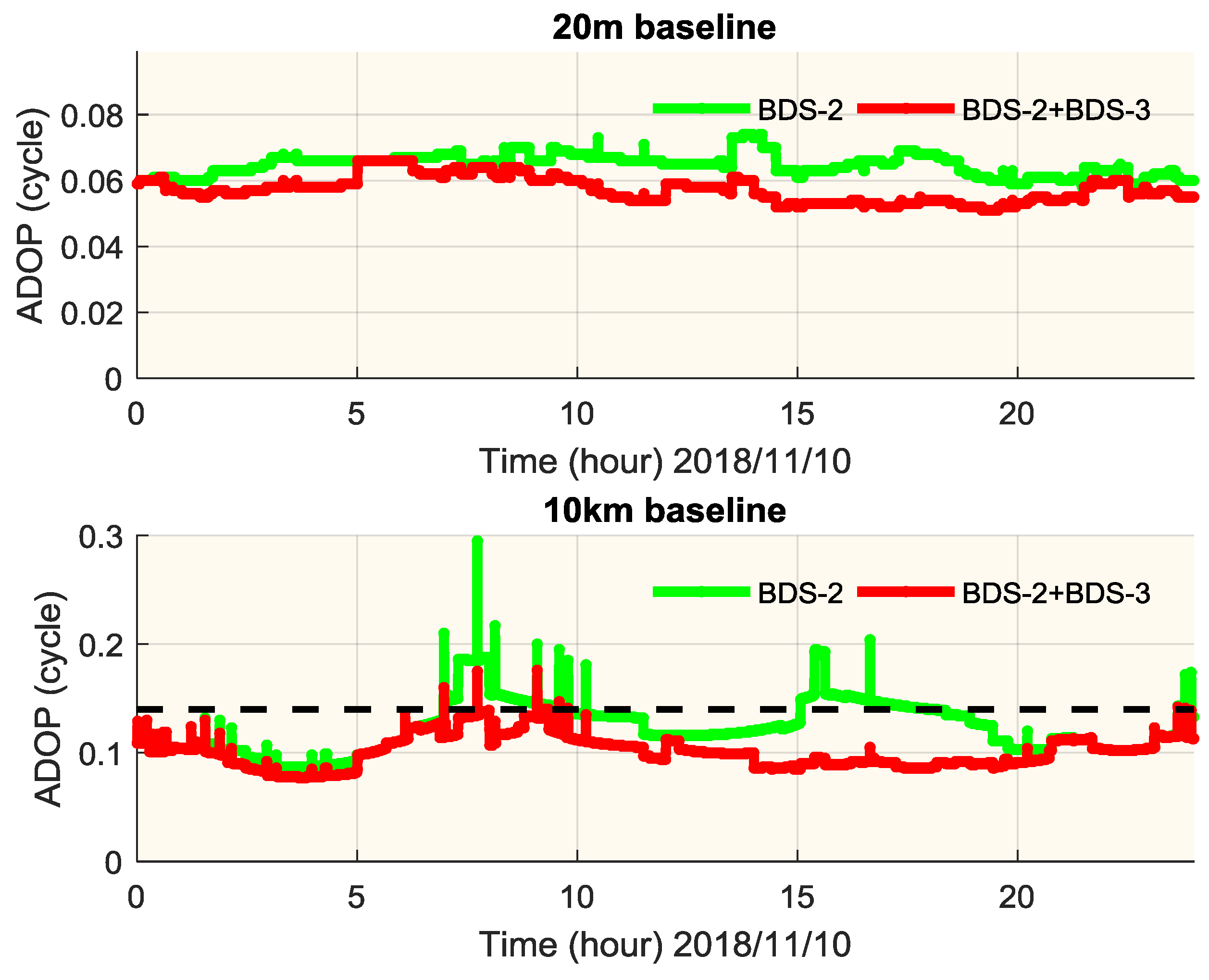
To analyze the contribution of BDS-3 in RTK, an epoch-by-epoch ADOP value is computed at the two baselines using BDS-2-only and BDS-2+BDS-3 satellites. As shown in Figure 14, the ADOP value at 20 m baseline is well below 0.14 cycle, which indicates the possibility of reliable ambiguity resolution for instantaneous RTK. While for 10 km baseline, ADOP is slightly worse than 20 m baseline due to satellite geometry. The percentage of ADOP below 0.14 cycle is 75.3% if BDS-2 is used, which could lead to wrong fixings for the ambiguity for instantaneous RTK. While for the BDS-2+BDS-3 combination, more than 99% of ADOP is below 0.14 cycle. In summary, for both baselines, ADOP performance would improve in different levels after BDS-3 satellites are added.
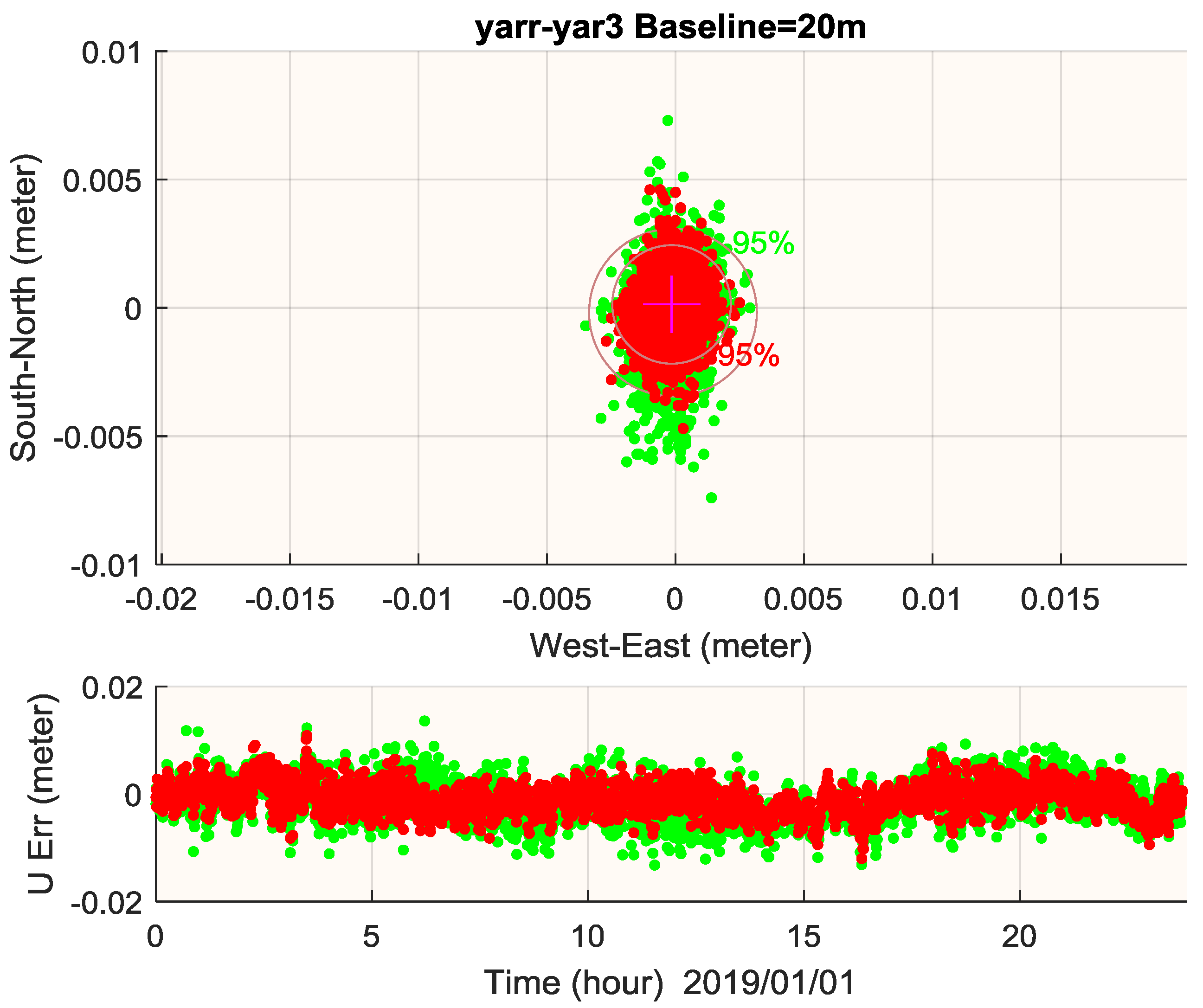
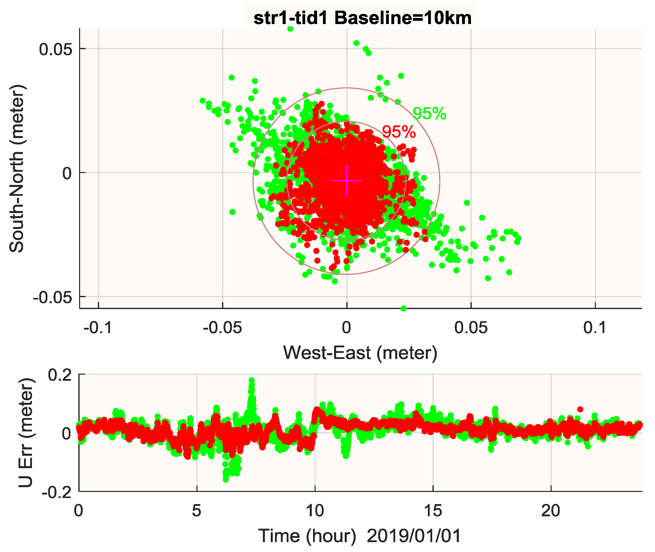
RTK performance of BDS-2-only and BDS-2+BDS-3 scenarios at these two baselines are depicted in Figure 15 and Figure 16, together with the statistical results of RMS and 95% accumulated error listed in Table 6. This illustrates that BDS-3 contributes to a more stable and precise RTK performance in the horizontal and vertical component, with a 1~2 mm improvement for 20 m baseline and 1~2 cm improvement for the 10 km baseline. Although it is not shown here, it should be pointed out that if we perform instantaneous RTK at the 10 km baseline [33], it would lead to some wrong ambiguity fixing for the BDS-2-only case.
6. Conclusions
With the official start of BDS-3 service, BDS has become a global navigation satellite system and more users can now benefit from BDS-only or BDS-combined multi-GNSS positioning. In this paper, we comprehensively assess the system status and the global positioning performance of BDS. Results show that:
- (1)
- With the contribution of new BDS-3 satellites, the global average number of BDS satellites increases from 5.1 to 10.7, thus the global position dilution of precision value would improve. According to analysis, the average position dilution of precision availability is around 98.84%, which meets the open service performance standard of BDS.
- (2)
- Signal in space range error of the current BDS constellation is 0.83 m. For BDS-3 satellites, it shows a 0.71 m performance, which is much better than BDS-2. After removing some BDS-3 satellites tracked by a few stations, the signal in space range error of BDS-3 is competitive with GPS and Galileo. We believe that with more BDS-3 satellites in space and the improvement of timing group delay accuracy, the overall signal in space range error of BDS would further improve.
- (3)
- For single point positioning performance on the B1I frequency, with a global RMS of accuracy at 1.1 m in horizontal and 2.2 m in vertical, BDS shows a similar accuracy with GPS. Comparing with BDS-2, BDS-3 greatly improves the positioning accuracy and service area of BDS. For the new B1c signal, it shows a similar performance in positioning with B1I. While for B2a, the positioning accuracy is much worse, which may come from the inaccurate precision of BDS ionosphere correction. Meanwhile, observation noise on B1c and B2a is much better than B1I.
- (4)
- BDS-3 also benefits real-time kinematic users in ambiguity dilution of precision and real-time kinematic performance in positioning accuracy and reliability.
To conclude, with a better signal in space range error and better position dilution of precision, PNT performance of BDS-3 will greatly improve in comparison with BDS-2, making BDS-3 a competitive global GNSS system. For the assessment of BDS signal in space range error, WUM final orbit and clock products are used. However, due to the still limited availability of BDS-3 tracking data, current precision of BDS-3 post-processed orbit and clock products are still lower than other GNSS systems. More precise products may be applied for BDS signal in space range error assessment in the future. Meanwhile, assessment of BDS-3 precise point positioning performance can also be conducted using the more precise products. With more stations tracking the B2a signal, it is expected that timing group delay accuracy would also improve.
Author Contributions
N.K. conceived the research framework; Y.Z. analyzed the data wrote the manuscript, J.C. and J.W. reviewed and revised the manuscript; H.W. collected the data and analyzed part of the data.
Funding
This research was funded by National Natural Science Foundation of China (No. 41874042 and No. 11673050) and Opening Project of Shanghai Key Laboratory of Space Navigation and Positioning Techniques (No. KFKT_201706).
Acknowledgments
We thank the GNSS observation data and products provided by IGS.
Conflicts of Interest
The authors declare no conflict of interest.
Abbreviations
| 3D | Three dimensions |
| ADOP | Ambiguity dilution of precision |
| APC | Antenna phase center |
| AR | Ambiguity resolution |
| BDS | BeiDou navigation satellite system |
| CAS | Chinese Academy of Science |
| CoM | Center of mass |
| DCB | Differential code bias |
| DOP | Dilution of precision |
| DOY | Day of year |
| GEO | Geosynchronous Earth Orbit |
| iGMAS | International GNSS Monitoring and Assessment System |
| IGS | International GNSS service |
| IGSO | Inclined Geosynchronous Orbit |
| ISL | Inter-satellite link |
| MEO | Medium Earth Orbit |
| OMC | Observation minus corrections |
| PCO | Phase center offset |
| PDOP | Position dilution of precision |
| POD | Precise orbit determination |
| SISRE | Signal in space range error |
| SPP | Single point positioning |
| PHM | Passive hydrogen maser |
| PNT | Positioning, navigation and timing |
| PPP | Precise point positioning |
| RTK | Real-time kinematic |
| TARC-CSNO | Test and Assessment Research Center of China Satellite Navigation Office |
| TGD | Timing group delay |
| UERE | User equivalent range error |
References
- China Satellite Navigation Office. BeiDou Navigation Satellite System Signal in Space Interface Control Document Open Service Signal (Version 2.1). Available online: http://www.beidou.gov.cn/xt/gfxz/201805/ P020180507527106075323.pdf (accessed on 24 April 2019).
- China Satellite Navigation Office. BeiDou Navigation Satellite System Open Service Performance Standard (Version 1.0). Available online: http://www.beidou.gov.cn/xt/gfxz/201805/P020180509584193805984.pdf (accessed on 24 April 2019).
- He, L.; Ge, M.; Wang, J.; Wickert, J.; Schuh, H. Experimental study on the precise orbit determination of the BeiDou navigation satellite system. Sensors 2013, 13, 2911–2928. [Google Scholar] [CrossRef]
- Yang, Y.; Li, J.; Wang, A.; Xu, J.; He, H.; Guo, H.; Dai, X. Preliminary assessment of the navigation and positioning performance of BeiDou regional navigation satellite system. Sci. China Earth Sci. 2014, 57, 144–152. [Google Scholar] [CrossRef]
- Wanninger, L.; Beer, S. BeiDou satellite-induced code pseudorange variations: Diagnosis and therapy. GPS Solut. 2015, 19, 639–648. [Google Scholar] [CrossRef]
- Shi, C.; Zhao, Q.; Hu, Z.; Liu, J. Precise relative positioning using real tracking data from COMPASS GEO and IGSO satellites. GPS Solut. 2013, 17, 103–119. [Google Scholar] [CrossRef]
- Li, M.; Qu, L.; Zhao, Q.; Guo, J.; Su, X.; Li, X. Precise point positioning with the BeiDou navigation satellite system. Sensors 2014, 14, 927–943. [Google Scholar] [CrossRef]
- China Satellite Navigation Office. BeiDou Navigation Satellite System Open Service Performance Standard (Version 2.0). Available online: http://www.beidou.gov.cn/xt/gfxz/201812/P020181227529449178798.pdf (accessed on 24 April 2019).
- China Satellite Navigation Office. Development of the BeiDou Navigation Satellite System (Version 3.0). Available online: http://www.beidou.gov.cn/xt/gfxz/201812/P020190117356387956569.pdf (accessed on 24 April 2019).
- Lu, M.; Li, W.; Yao, Z.; Cui, X. Overview of BDS III new signals. Navigation 2019, 66, 19–35. [Google Scholar] [CrossRef] [Green Version]
- Tang, C.; Hu, X.; Zhou, S.; Liu, L.; Pan, J.; Chen, L.; He, F. Initial results of centralized autonomous orbit determination of the new-generation BDS satellites with inter-satellite link measurements. J. Geod. 2018, 92, 1155–1169. [Google Scholar] [CrossRef]
- Xie, X.; Geng, T.; Zhao, Q.; Cai, H.; Zhang, F.; Wang, X.; Meng, Y. Precise orbit determination for BDS-3 satellites using satellite-ground and inter-satellite link observations. GPS Solut. 2019, 23, 40. [Google Scholar] [CrossRef]
- Wang, C.; Zhao, Q.; Guo, J.; Liu, J.; Chen, G. The contribution of intersatellite links to BDS-3 orbit determination: Model refinement and comparisons. Navigation 2019, 66. [Google Scholar] [CrossRef]
- Wu, Z.; Zhou, S.; Hu, X.; Liu, L.; Shuai, T.; Xie, Y.; Chang, Z. Performance of the BDS3 experimental satellite passive hydrogen maser. GPS Solut. 2018, 43. [Google Scholar] [CrossRef]
- Zhang, X.; Wu, M.; Liu, W.; Li, X.; Yu, S.; Lu, C.; Wickert, J. Initial assessment of the COMPASS/BeiDou-3: New-generation navigation signals. J. Geod. 2017, 91, 1225–1240. [Google Scholar] [CrossRef]
- Zhang, R.; Tu, R.; Liu, J.; Hong, J.; Fan, L.; Zhang, P.; Lu, X. Impact of BDS-3 experimental satellites to BDS-2: Service area, precise products, precise positioning. Adv. Space Res. 2018, 62, 829–844. [Google Scholar] [CrossRef]
- Yang, Y.; Xu, Y.; Li, J.; Yang, C. Progress and performance evaluation of BeiDou global navigation satellite system: Data analysis based on BDS-3 demonstration system. Sci. China Earth Sci. 2018, 61, 614–624. [Google Scholar] [CrossRef]
- Wang, M.; Wang, J.; Dong, D.; Meng, L.; Chen, J.; Wang, A.; Cui, H. Performance of BDS-3: Satellite visibility and dilution of precision. GPS Solut. 2019, 23, 56. [Google Scholar] [CrossRef]
- Yang, Y.; Gao, W.; Guo, S.; Mao, Y.; Yang, Y. Introduction to BeiDou-3 navigation satellite system. Navigation 2019, 66. [Google Scholar] [CrossRef]
- Jay, A.; Jan, W. GNSS/INS Integration. In Springer Handbook of Global Navigation Satellite Systems; Teunissen, P., Montenbruck, O., Eds.; Springer: Gewerbestrasse, Switzerland, 2017; Chapter 28; p. 812. [Google Scholar]
- Montenbruck, O.; Steigenberger, P.; Hauschild, A. Broadcast versus precise ephemerides: A multi-GNSS perspective. GPS Solut. 2015, 19, 321–333. [Google Scholar] [CrossRef]
- Zhang, Y.; Chen, J.; Zhou, J.; Yang, S.; Wang, B.; Chen, Q.; Gong, X. Analysis and application of BDS broadcast ephemeris bias. Acta Geod. Cartogr. Sin. 2016, 45, 64–71. [Google Scholar]
- Wu, Y.; Liu, X.; Liu, W.; Ren, J.; Lou, Y.; Dai, X.; Fang, X. Long-term behavior and statistical characterization of BeiDou signal-in-space errors. GPS Solut. 2017, 21, 1907–1922. [Google Scholar] [CrossRef]
- Montenbruck, O.; Steigenberger, P.; Hauschild, A. Multi-GNSS signal-in-space range error assessment–Methodology and results. Adv. Space Res. 2018, 61, 3020–3038. [Google Scholar] [CrossRef]
- Guo, J. Multi-GNSS Analysis at Wuhan University: Attitude, Solar Radiation Pressure, Phase Center, and More. Available online: https://www.researchgate.net/project/Multi-GNSS-analysis-at-Wuhan-University-attitude-solar-radiation-pressure-phase-center-and-more/update/5c7957c33843b034242dd188 (accessed on 24 April 2019).
- Wang, B.; Chen, J.; Wang, B.; Zhou, J. Signal-in-space Accuracy Analysis for BDS in 2016–2017. In Proceedings of the IGS Workshop 2018, Wuhan, China, 29 October–2 November 2018. [Google Scholar]
- Guo, J.; Xu, X.; Zhao, Q.; Liu, J. Precise orbit determination for quad-constellation satellites at Wuhan University: Strategy, result validation, and comparison. J. Geod. 2016, 90, 143–159. [Google Scholar] [CrossRef]
- Guo, F.; Zhang, X.; Wang, J. Timing group delay and differential code bias corrections for BeiDou positioning. J. Geod. 2015, 89, 427–445. [Google Scholar] [CrossRef]
- Wang, N.; Yuan, Y.; Li, Z.; Montenbruck, O.; Tan, B. Determination of differential code biases with multi-GNSS observations. J. Geod. 2016, 90, 209–228. [Google Scholar] [CrossRef]
- Deng, Z. BDS Orbit Determination at GFZ. In Proceedings of the China Satellite Navigation Conference, Beijing, China, 22–25 May 2019. [Google Scholar]
- Montenbruck, O.; Steigenberger, P.; Prange, L.; Deng, Z.; Zhao, Q.; Perosanz, F.; Schmid, R. The Multi-GNSS Experiment (MGEX) of the International GNSS Service (IGS)–achievements, prospects and challenges. Adv. Space Res. 2017, 59, 1671–1697. [Google Scholar] [CrossRef]
- Böhm, J.; Möller, G.; Schindelegger, M.; Pain, G.; Weber, R. Development of an improved empirical model for slant delays in the troposphere (GPT2w). GPS Solut. 2015, 19, 433–441. [Google Scholar]
- Takasu, T. RTKLIB ver. 2.4. 2 Manual. RTKLIB: An Open Source Program Package for GNSS Positioning. Available online: http://www.rtklib.com/prog/manual_2.4.2.pdf (accessed on 24 April 2019).
- Teunissen, P.J. The least-squares ambiguity decorrelation adjustment: A method for fast GPS integer ambiguity estimation. J. Geod. 1995, 70, 65–82. [Google Scholar] [CrossRef]
- Teunissen, P.J. A canonical theory for short GPS baselines. Part IV: Precision versus reliability. J. Geod. 1997, 71, 513–525. [Google Scholar] [CrossRef]
- Odijk, D.; Teunissen, P.J.G. ADOP in closed form for a hierarchy of multi-frequency single-baseline GNSS models. J. Geod. 2008, 82, 473–492. [Google Scholar] [CrossRef] [Green Version]
Figure 1.
Average visible satellite number comparison of BDS-2 (upper) and BDS-2+BDS-3 (lower) for an elevation angle mask of 10° on 1 January 2019.
Figure 1.
Average visible satellite number comparison of BDS-2 (upper) and BDS-2+BDS-3 (lower) for an elevation angle mask of 10° on 1 January 2019.
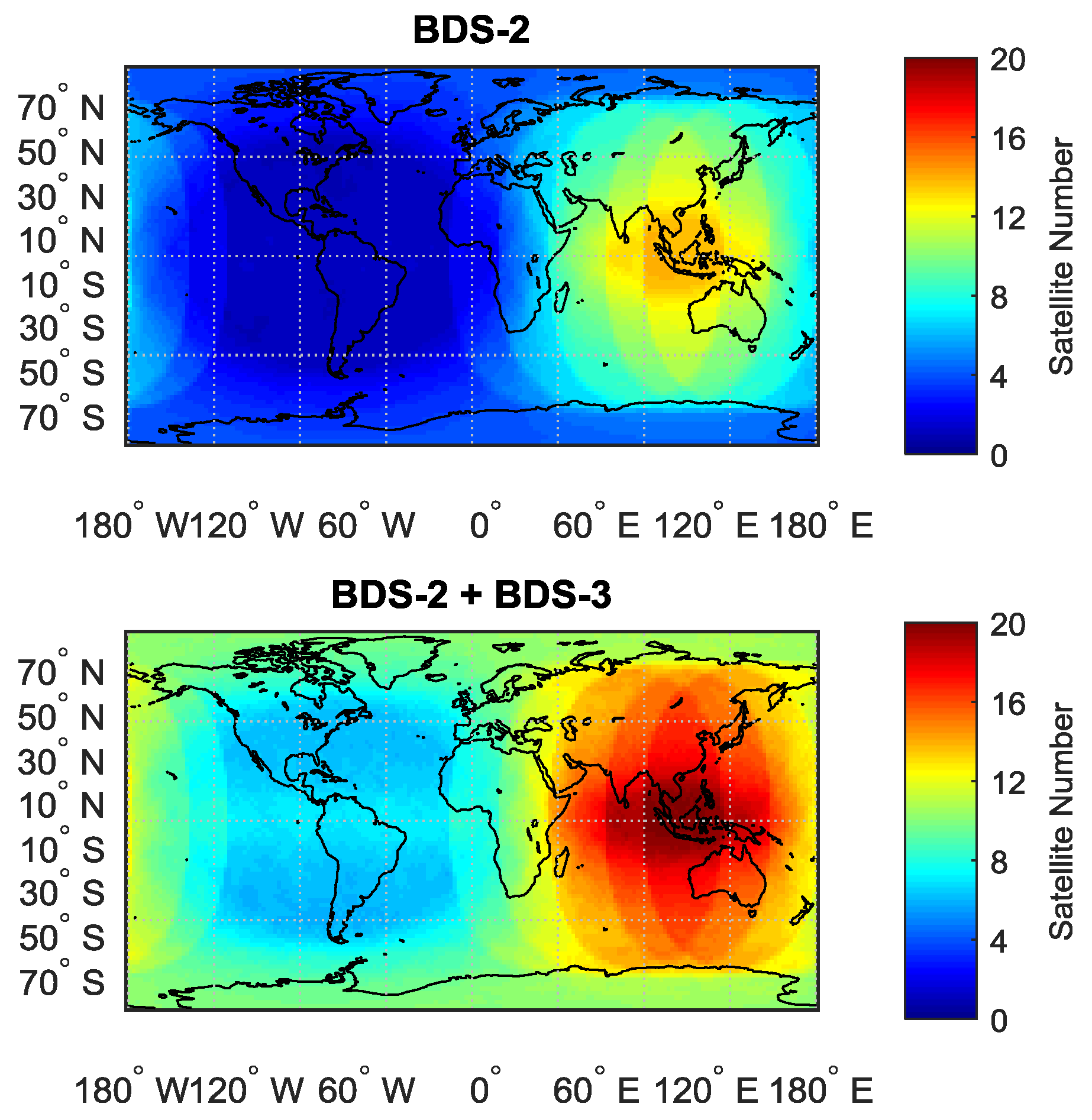
Figure 2.
Average PDOP value of BDS-2 (upper) and BDS-2+BDS-3 (lower) for an elevation angle mask of 10° on 1 January 2019. Only value of PDOP < 6 is counted.
Figure 2.
Average PDOP value of BDS-2 (upper) and BDS-2+BDS-3 (lower) for an elevation angle mask of 10° on 1 January 2019. Only value of PDOP < 6 is counted.
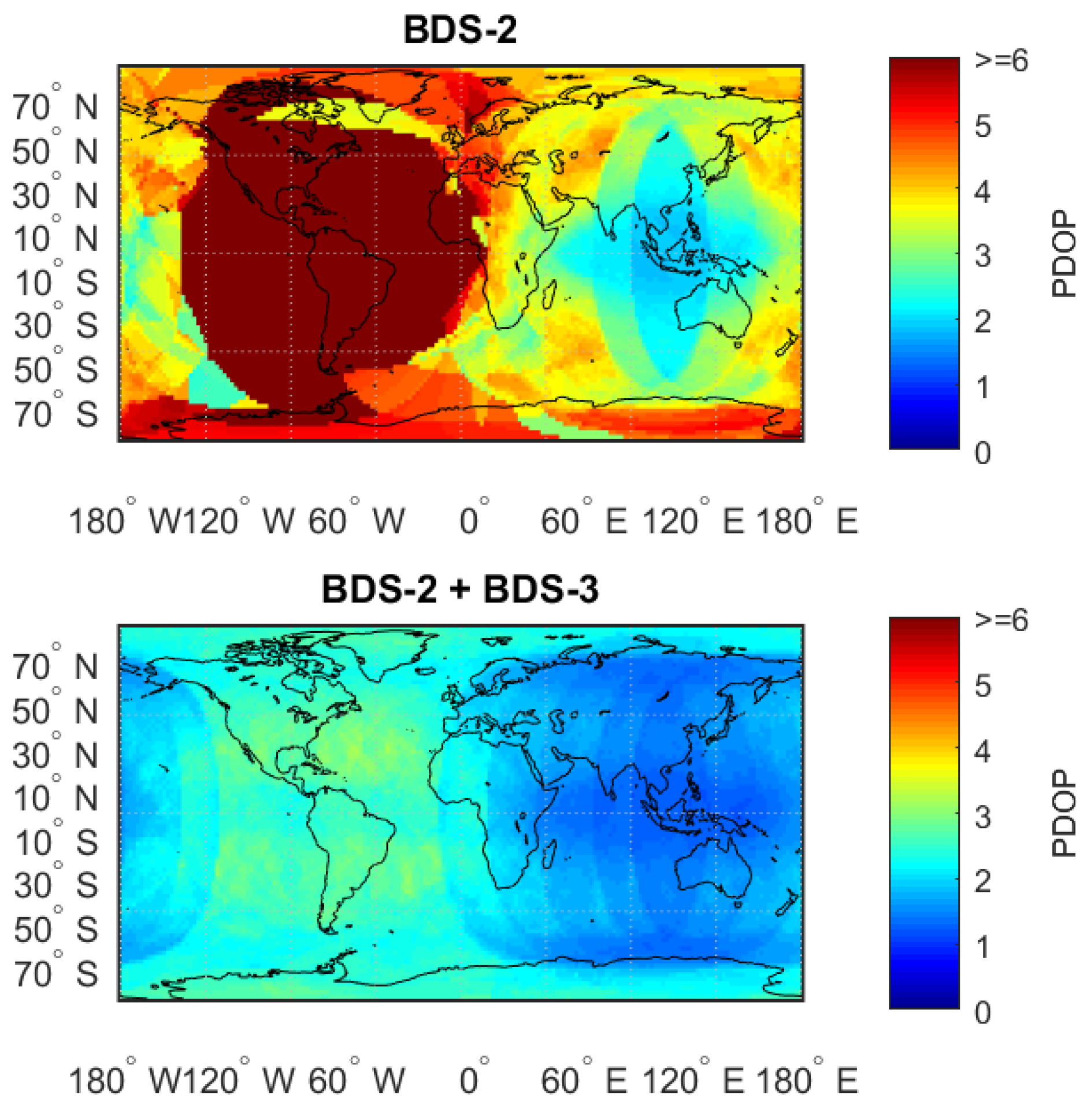
Figure 3.
PDOP availability (PDOP < 6) for BDS-2 (upper) and BDS-2+BDS-3 (lower) for an elevation angle mask of 10° on 1 January 2019.
Figure 3.
PDOP availability (PDOP < 6) for BDS-2 (upper) and BDS-2+BDS-3 (lower) for an elevation angle mask of 10° on 1 January 2019.
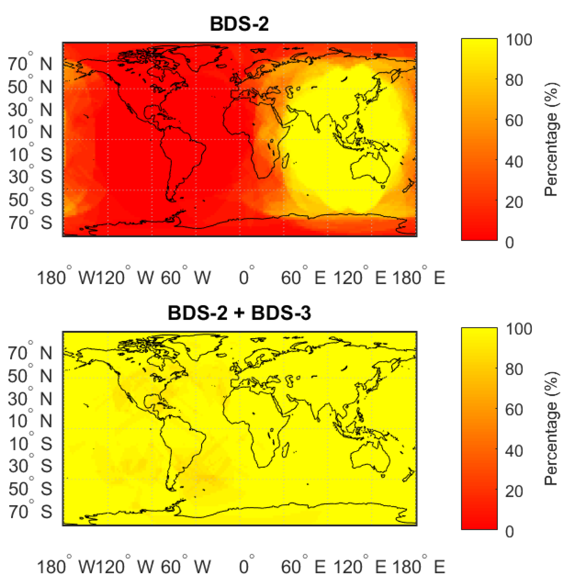
Figure 4.
SISRE of BDS-2 (upper) and BDS-3 (lower) satellites on B1I/B3I ionosphere-free combination frequency, satellite clock difference is corrected by TGD or DCB.
Figure 4.
SISRE of BDS-2 (upper) and BDS-3 (lower) satellites on B1I/B3I ionosphere-free combination frequency, satellite clock difference is corrected by TGD or DCB.

Figure 5.
Fifty-four globally distributed IGS stations (including 13 JAVAD receivers and 41 SEPTENTRIO receivers).
Figure 5.
Fifty-four globally distributed IGS stations (including 13 JAVAD receivers and 41 SEPTENTRIO receivers).

Figure 6.
RMS of SPP performance in horizontal (upper) and vertical (lower) using current BDS constellation (54 stations, one week).
Figure 6.
RMS of SPP performance in horizontal (upper) and vertical (lower) using current BDS constellation (54 stations, one week).

Figure 7.
RMS of SPP performance for BDS-2-only (left) and BDS-2+BDS-3 (right) around the Asia-Pacific and Indian Ocean region (20 stations, one week). Please note the different scale of the legend.
Figure 7.
RMS of SPP performance for BDS-2-only (left) and BDS-2+BDS-3 (right) around the Asia-Pacific and Indian Ocean region (20 stations, one week). Please note the different scale of the legend.

Figure 8.
Visible satellite number at station SGOC for an elevation angle mask of 10° on 13 January 2019.
Figure 8.
Visible satellite number at station SGOC for an elevation angle mask of 10° on 13 January 2019.

Figure 9.
SPP comparison of BDS-2 only (green) and BDS-2+BDS-3 (red) at station SGOC in North (upper), East (middle) and Up (lower) component.
Figure 9.
SPP comparison of BDS-2 only (green) and BDS-2+BDS-3 (red) at station SGOC in North (upper), East (middle) and Up (lower) component.
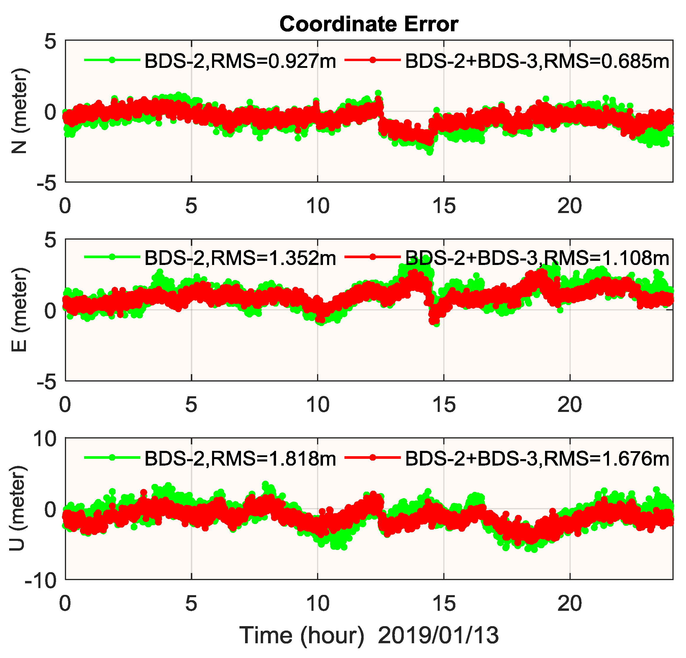
Figure 10.
RMS of SPP performance of B1I, B1c and B2a at horizontal (upper) and vertical (lower) component (BDS-3-only, one week).
Figure 10.
RMS of SPP performance of B1I, B1c and B2a at horizontal (upper) and vertical (lower) component (BDS-3-only, one week).
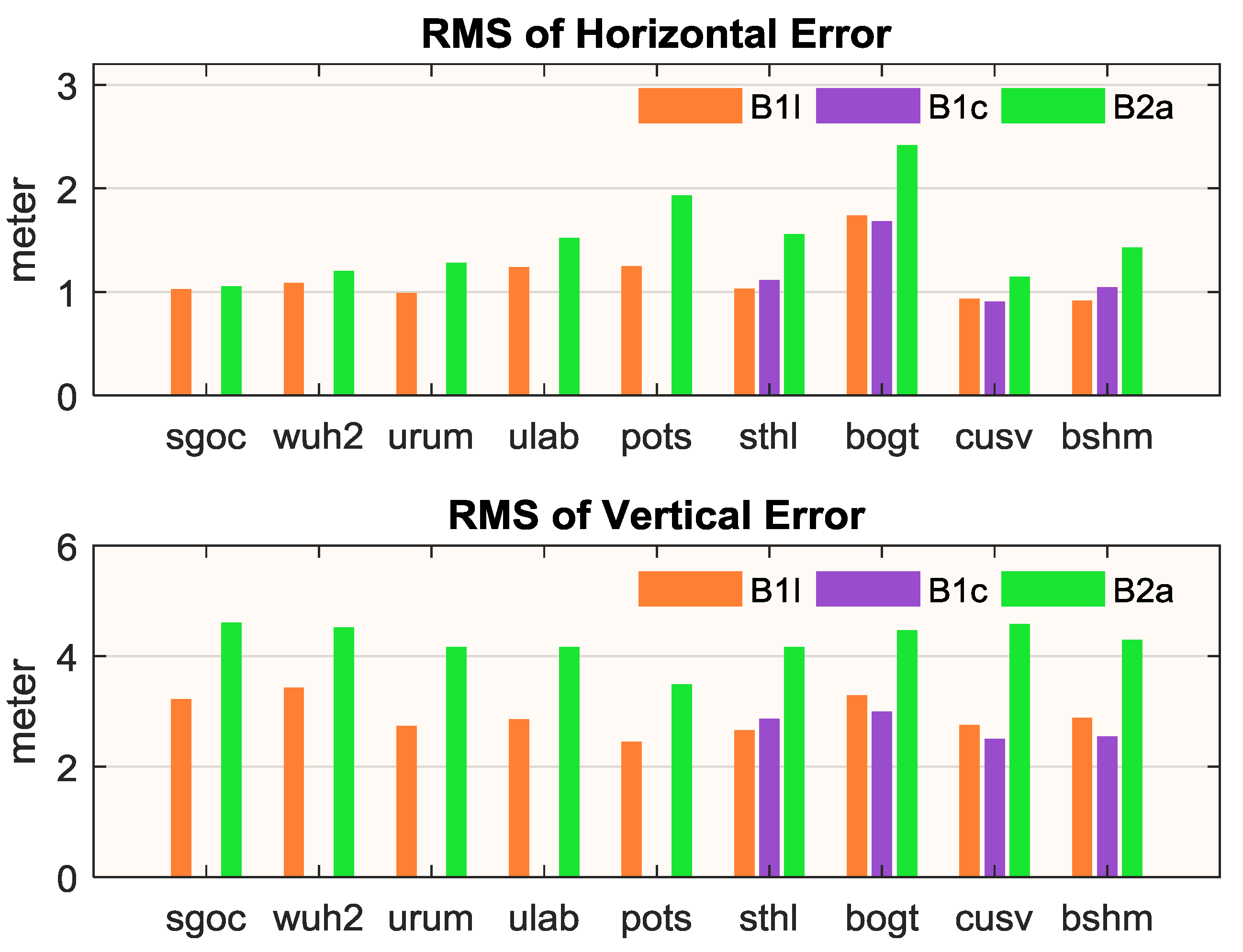
Figure 11.
Satellite number and PDOP of BDS-3 at station BSHM.

Figure 12.
SPP comparison of B1I (upper), B1c (middle) and B2a (lower) at station BSHM (BDS-3 only).
Figure 12.
SPP comparison of B1I (upper), B1c (middle) and B2a (lower) at station BSHM (BDS-3 only).
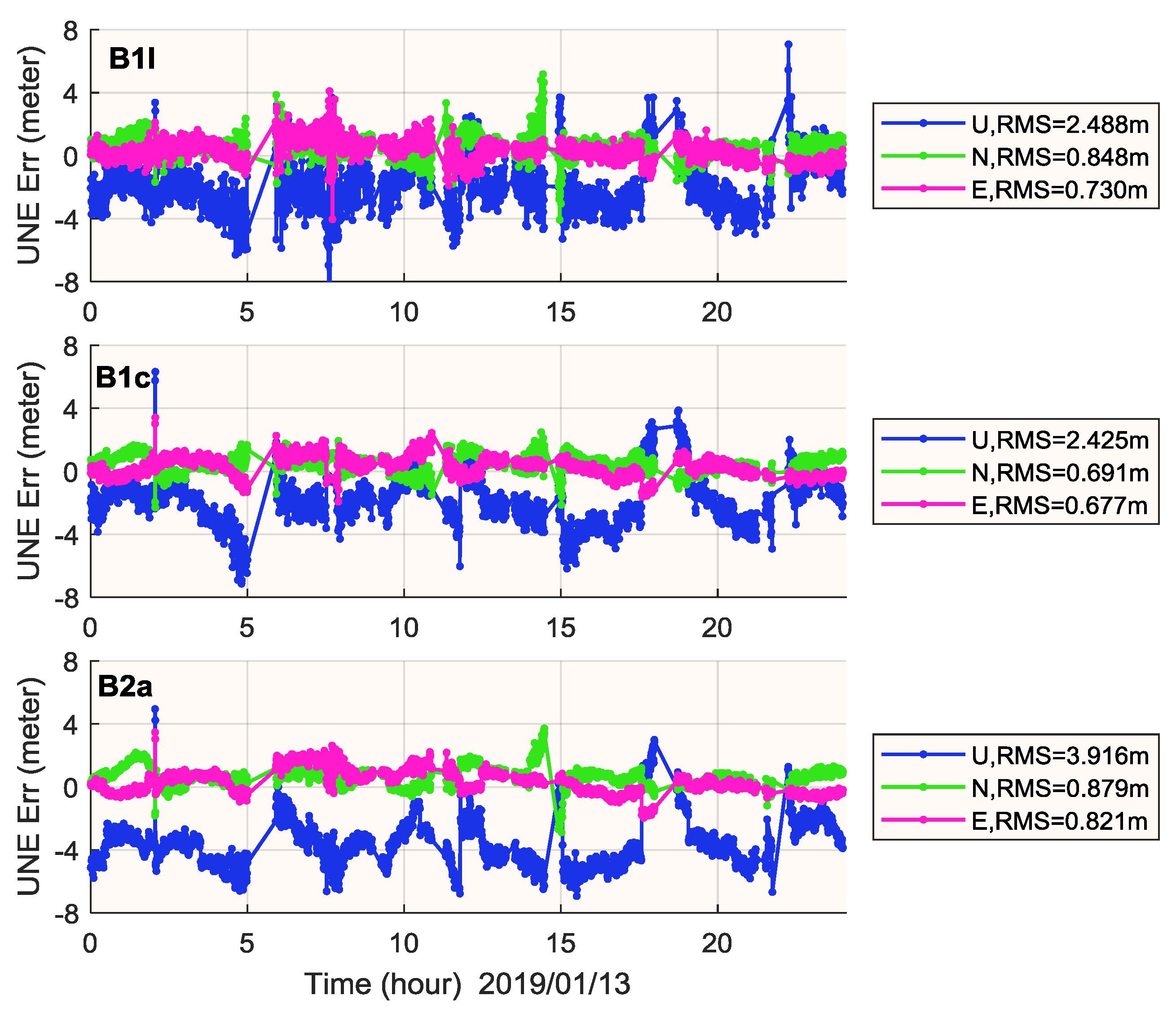
Figure 13.
OMC of B1I (upper), B1c (middle) and B2a (lower) at station BSHM. Different color means different satellite in each subplot. OMC may contain residual error of receiver clock, but it is the same for each satellite at the same epoch.
Figure 13.
OMC of B1I (upper), B1c (middle) and B2a (lower) at station BSHM. Different color means different satellite in each subplot. OMC may contain residual error of receiver clock, but it is the same for each satellite at the same epoch.

Figure 14.
Epoch-by-epoch ADOP of BDS-2-only and BDS-2+BDS-3 at 20 m baseline (upper) and 10 km baseline (lower). The black dashed line refers to an ADOP value of 0.14 cycle.
Figure 14.
Epoch-by-epoch ADOP of BDS-2-only and BDS-2+BDS-3 at 20 m baseline (upper) and 10 km baseline (lower). The black dashed line refers to an ADOP value of 0.14 cycle.

Figure 15.
Twenty m baseline RTK performance in horizontal (upper) and vertical (lower) using BDS-2-only (green) and BDS-2+BDS-3 (red). The gray circle shows the 95% confidence level of horizontal error. Ambiguity fix percentage is 100% for both cases.
Figure 15.
Twenty m baseline RTK performance in horizontal (upper) and vertical (lower) using BDS-2-only (green) and BDS-2+BDS-3 (red). The gray circle shows the 95% confidence level of horizontal error. Ambiguity fix percentage is 100% for both cases.

Figure 16.
Ten km baseline RTK performance in horizontal (upper) and vertical (lower) using BDS-2-only (green) and BDS-2+BDS-3 (red). The gray circle shows the 95% confidence level of horizontal error. Ambiguity fix percentage is 100% for both cases.
Figure 16.
Ten km baseline RTK performance in horizontal (upper) and vertical (lower) using BDS-2-only (green) and BDS-2+BDS-3 (red). The gray circle shows the 95% confidence level of horizontal error. Ambiguity fix percentage is 100% for both cases.


Table 1.
Satellite number and PDOP availability (PODP < 6) for BDS-2 and BDS-2+BDS-3 for an elevation angle mask of 10° on 1 January 2019.
Table 1.
Satellite number and PDOP availability (PODP < 6) for BDS-2 and BDS-2+BDS-3 for an elevation angle mask of 10° on 1 January 2019.
| Property | BDS-2 | BDS-2+BDS-3 | ||||
|---|---|---|---|---|---|---|
| Min | Max | Average | Min | Max | Average | |
| Satellite Number | 0.9 | 13.8 | 5.1 | 5.7 | 20 | 10.7 |
| PDOP Availability | 0% | 100% | 35.25% | 79.17% | 100% | 98.84% |
Table 2.
Average SISRE of BDS-2 and BDS-3 from DOY 010 to 070 in 2019 (in m).
| Type | BDS-2 | BDS-3 | BDS-2+BDS-3 |
|---|---|---|---|
| TGD correction | 0.96 | 0.71 | 0.83 |
| DCB correction | 0.90 | 0.57 | 0.71 |
Table 3.
SPP performance of current BDS and GPS system (in meter).
| System | RMS | 95% | ||||
|---|---|---|---|---|---|---|
| North | East | Up | North | East | Up | |
| BDS | 0.90 | 0.64 | 2.16 | 1.69 | 1.22 | 3.89 |
| GPS | 0.80 | 0.47 | 2.12 | 1.50 | 0.95 | 3.72 |
Table 4.
BDS-2-only and BDS-2+BDS-3 SPP performance around the Asia-Pacific and Indian Ocean region (in m). The results are from one-week of data for 20 stations.
Table 4.
BDS-2-only and BDS-2+BDS-3 SPP performance around the Asia-Pacific and Indian Ocean region (in m). The results are from one-week of data for 20 stations.
| System | RMS | 95% | ||||
|---|---|---|---|---|---|---|
| North | East | Up | North | East | Up | |
| BDS2-only | 0.96 | 1.10 | 4.13 | 1.91 | 2.08 | 6.05 |
| BDS-2+BDS-3 | 0.72 | 0.56 | 2.24 | 1.34 | 1.07 | 3.93 |
Table 5.
SPP performance of B1I, B1c and B2a (in meter). The results are from one-week of data.
| Frequency | RMS | 95% | ||||
|---|---|---|---|---|---|---|
| North | East | Up | North | East | Up | |
| B1I | 0.87 | 0.71 | 2.92 | 1.65 | 1.32 | 4.89 |
| B1c | 0.91 | 0.74 | 2.73 | 1.81 | 1.51 | 4.52 |
| B2a | 1.24 | 0.80 | 4.27 | 2.27 | 1.55 | 6.49 |
Table 6.
RTK performance of BDS-2-only and BDS-2+3 for 20 m baseline and 10 km baseline (in meter).
| Baseline | System | RMS | 95% | ||
|---|---|---|---|---|---|
| Horizontal | Vertical | Horizontal | Vertical | ||
| 20 m | BDS-2-only | 0.0017 | 0.0038 | 0.0033 | 0.0074 |
| BDS-2+BDS-3 | 00013 | 0.0028 | 0.0023 | 0.0054 | |
| 10 km | BDS-2-only | 0.0190 | 0.0352 | 0.0376 | 0.0682 |
| BDS-2+BDS-3 | 0.0122 | 0.0252 | 0.0240 | 0.0470 | |
© 2019 by the authors. Licensee MDPI, Basel, Switzerland. This article is an open access article distributed under the terms and conditions of the Creative Commons Attribution (CC BY) license (http://creativecommons.org/licenses/by/4.0/).
Share and Cite
MDPI and ACS Style
Zhang, Y.; Kubo, N.; Chen, J.; Wang, J.; Wang, H. Initial Positioning Assessment of BDS New Satellites and New Signals. Remote Sens. 2019, 11, 1320. https://doi.org/10.3390/rs11111320
AMA Style
Zhang Y, Kubo N, Chen J, Wang J, Wang H. Initial Positioning Assessment of BDS New Satellites and New Signals. Remote Sensing. 2019; 11(11):1320. https://doi.org/10.3390/rs11111320
Chicago/Turabian StyleZhang, Yize, Nobuaki Kubo, Junping Chen, Jiexian Wang, and Hu Wang. 2019. "Initial Positioning Assessment of BDS New Satellites and New Signals" Remote Sensing 11, no. 11: 1320. https://doi.org/10.3390/rs11111320
Note that from the first issue of 2016, this journal uses article numbers instead of page numbers. See further details here.