Article

Assessing the Accuracy of Automatically Extracted Shorelines on Microtidal Beaches from Landsat 7, Landsat 8 and Sentinel-2 Imagery

1
Geo-Environmental Cartography and Remote Sensing Group, Department of Cartographic Engineering, Geodesy and Photogrammetry, Universitat Politècnica de València, Camí de Vera s/n, 46022 Valencia, Spain
2
Department of Cartographic Engineering, Geodesy and Photogrammetry, Universitat Politècnica de València., Camí de Vera s/n, 46022 Valencia, Spain
3
Department of Applied Mathematics, Universitat Politècnica de València, Camí de Vera s/n, 46022 Valencia, Spain
*
Author to whom correspondence should be addressed.
Remote Sens. 2018, 10(2), 326; https://doi.org/10.3390/rs10020326
Submission received: 30 November 2017 / Revised: 11 February 2018 / Accepted: 19 February 2018 / Published: 22 February 2018
(This article belongs to the Section Remote Sensing in Geology, Geomorphology and Hydrology)

Abstract

:
This paper evaluates the accuracy of shoreline positions obtained from the infrared (IR) bands of Landsat 7, Landsat 8, and Sentinel-2 imagery on natural beaches. A workflow for sub-pixel shoreline extraction, already tested on seawalls, is used. The present work analyzes the behavior of that workflow and resultant shorelines on a micro-tidal (<20 cm) sandy beach and makes a comparison with other more accurate sets of shorelines. These other sets were obtained using differential GNSS surveys and terrestrial photogrammetry techniques through the C-Pro monitoring system. 21 sub-pixel shorelines and their respective high-precision lines served for the evaluation. The results prove that NIR bands can easily confuse the shoreline with whitewater, whereas SWIR bands are more reliable in this respect. Moreover, it verifies that shorelines obtained from bands 11 and 12 of Sentinel-2 are very similar to those obtained with bands 6 and 7 of Landsat 8 (−0.75 ± 2.5 m; negative sign indicates landward bias). The variability of the brightness in the terrestrial zone influences shoreline detection: brighter zones cause a small landward bias. A relation between the swell and shoreline accuracy is found, mainly identified in images obtained from Landsat 8 and Sentinel-2. On natural beaches, the mean shoreline error varies with the type of image used. After analyzing the whole set of shorelines detected from Landsat 7, we conclude that the mean horizontal error is 4.63 m (±6.55 m) and 5.50 m (±4.86 m), respectively, for high and low gain images. For the Landsat 8 and Sentinel-2 shorelines, the mean error reaches 3.06 m (±5.79 m).

Graphical Abstract

1. Introduction

The shoreline is a morphological feature that is often used to understand how beach systems work and how their development is affected by mid- to long-term processes. However, the definition of shoreline may be difficult as many different indicators are used in the bibliography, especially in macro-tidal coasts [1]. While the water/land line has been used in micro-tidal zones, the dry/wet sand line has been used in the macro-tidal area (understanding it as the shoreline for the last highest tidal position). Traditionally, the main data source for shoreline acquisition has been aerial imagery [2,3,4]. However, some authors [5,6,7,8] have criticized this shoreline because it may be affected by the sea level. They prefer to use the isohypse at the highest tidal position (datum-based shoreline) as it would be more reliable for beach profile changes. This 3D information is normally obtained by GNSS mapping (Global Navigation Satellite System) [9,10], LiDAR [11,12,13,14] or TLS [15] (Terrestrial Laser Scanner). These 3D resources may offer high accuracy data: up to 5 cm (horizontal and vertical) on differential GNSS surveys; and up to 10 cm (horizontal) and 20 cm (vertical) depending on each of the LiDAR flight demands. Nevertheless, mapping hundreds of kilometers at a high frequency may be difficult.
Although 3D data offers more complete information, other works show that 2D sources are also useful. Video-monitoring techniques [16,17,18], given that they can record the shoreline with high frequency, are useful in dynamic areas such as sandy beaches (the variability of the beach and the most landward shoreline position during a storm can be obtained almost in real time). The mean shoreline position may be calculated on an hourly, daily, or weekly bases for trend studies. The main constraint for video-monitorization is that it only works with very limited spaces, normally urban beaches where a camera can be installed on a building. To cover wider areas (hundreds of kilometers), both optical [19,20] and radar [21] satellite imagery is used—but these techniques remain limited by the temporal frequency of satellite observations. This lack of frequency may cause problems when measuring natural beaches, as the shoreline position may be so affected by the sea level that its position loses geomorphological meaning. However, compiling tens of instantaneous shorelines during a specific time period may be useful for estimating mean shoreline positions and trends during the medium and long term [22].
Landsat is one of the most used satellite imagery options, especially since the USGS announced in 2008 that the images would be freely available. New research became possible as, through Landsat 5, 7 and 8 (with a revisit period of 16 days), dozens of images may be obtained for the same place during a year. Furthermore, historical series are available as Landsat 5 has been recording data from 1984 to 2011, Landsat 7 from 1999, and Landsat 8 from 2013. Following the same free availability criteria, since June 2015, the ESA (European Space Agency) satellite Sentinel-2A has been capturing images with a higher spatial and temporal resolution than Landsat 8. Working together with its newest twin Sentinel-2B—launched in March 2017—the frequency of Sentinel-2 image registration has increased to five days (and even two or three days in medium latitudes). The combination of Landsat 8, Sentinel-2A, and Sentinel-2B provides a global median average revisit interval of 2.9 days [23].
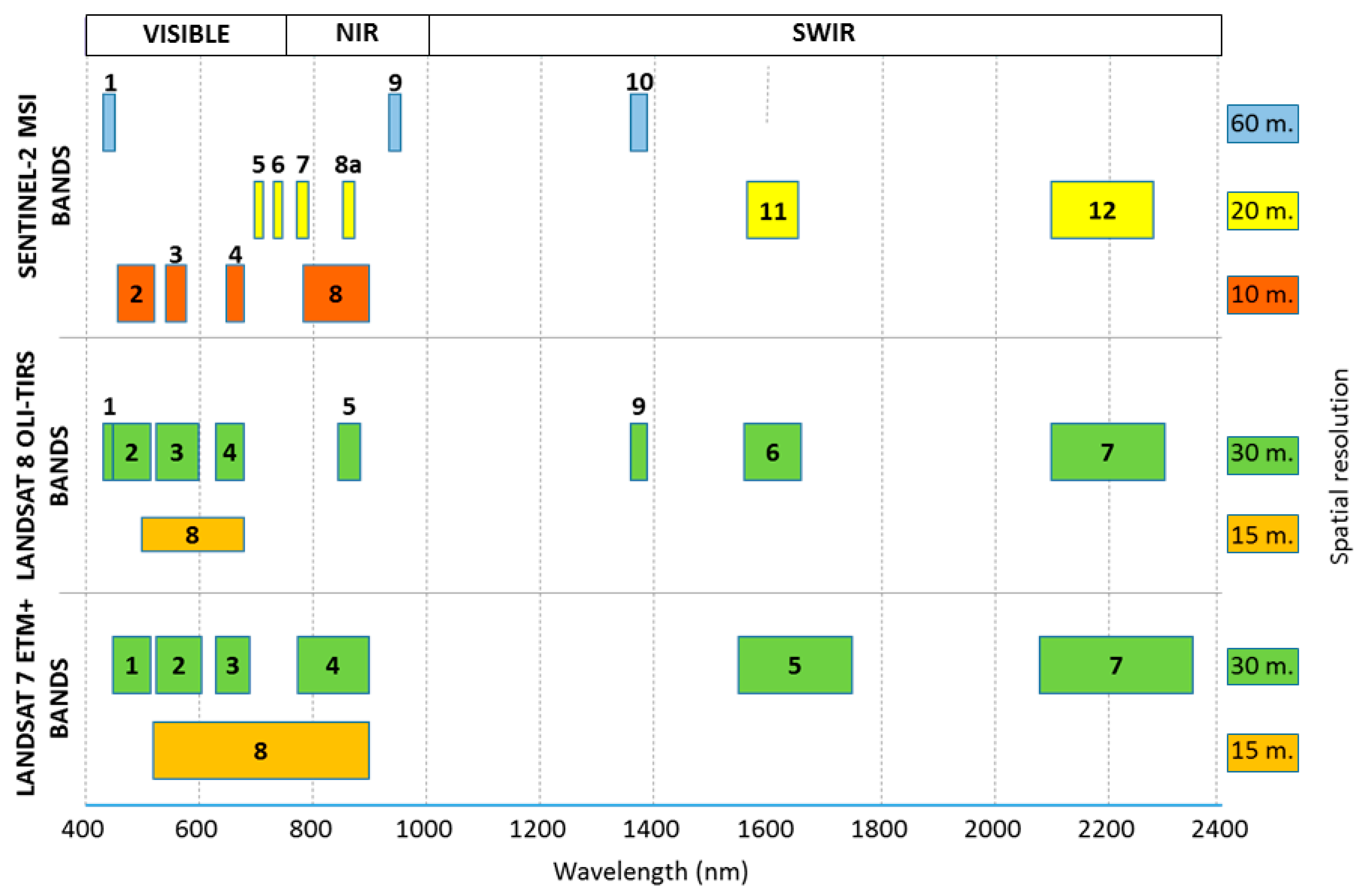
Figure 1 shows a comparison between Landsat (7 and 8) and Sentinel-2. Specifically, it shows the spectral and spatial information of ETM+ (Enhanced Thematic Mapper Plus), OLI (Operational Land Imager), and MSI (MultiSpectral Instrument) sensors, belonging to Landsat 7, Landsat 8, and Sentinel-2A satellites, respectively. The NIR (near infrared) region between Landsat 8 (band 5) and Sentinel-2A (band 8A) are similar, but differ significantly to band 4 in Landsat 7 (with a very much greater bandwidth). The same occurs in SWIR (short wave infrared), where bands 6 and 7 from Landsat 8 are very similar to bands 11 and 12 from Sentinel-2A, while bands 5 and 7 from Landsat 7 have greater bandwidth.
Common characteristics between Landsat (7 and 8) and Sentinel-2 justify researching workflows that may be used equivalently. The differences must be considered when a workflow results in different outcomes. These data sources represent an opportunity to improve our understanding of coastal dynamics worldwide (including beach trend evolution, local beach changes, coastal storm impact evaluation and recovery beach processes, re-nourishment monitoring, and assessments of the effects of coastal infrastructures).
The main limitation of using Landsat and Sentinel 2 imagery is that their 20 m or 30 m spatial resolutions may be insufficient for the task. Although they have been used to quantify changes in very dynamic areas such as deltas [24,25,26,27], or water bodies [28,29,30,31], the pixel size limitation must be overcome for tasks needing more detail.
Obtaining sub-pixel shorelines requires solving two tasks: (i) mapping the shoreline with greater accuracy than the pixel size; and (ii) ensuring a geolocation that is also finer than the pixel size. The first step is processed into the space of the same image, while the second needs a reference image. This registration is needed if several shorelines are to be compared, if the images are to be used for a trend study, or if a shoreline must be evaluated with a reference line mapped using more accurate techniques.
The most common extraction techniques for sub-pixel shorelines involve soft classification and super-resolution mapping [32,33,34]. These techniques try to discover the water-land edge within each pixel but have some constraints derived from the level of resampling which could cause problems in connections and a lack of smoothness in the final delineated line. Li et al. [35] propose integrating back-propagation neural networks and genetic algorithms to achieve a super-resolution mapping of flooded wetland. Li et al. [36] describe a multiple super-resolution mapping method, obtaining results that are more accurate than those obtained using an individual method. Shi et al. [37] propose a method that combines multiple super-resolution realizations obtained using the indicator-geostatistics-based method. Liu et al. [38] propose a method to obtain a super-resolution shoreline based on a segmentation method previously proposed by Cipolleti et al. [39]. In this method, after obtaining an initial shoreline by applying a thresholding classification, the most probable line position within a 2 × 2 kernel is assessed. A similar proposal was applied by Ruiz et al. [40] being later modified and assessed by Pardo-Pascual et al. [41], as well as being improved by Almonacid-Caballer [42]. The algorithm starts with the detection of a pixel level shoreline and, by fitting a 5th-degree polynomial function around each of these pixels, detects the inflexion line where the shoreline is expected to be. This is the methodology followed in this paper.
Although both Landsat and Sentinel-2 scenes are georeferenced, small inconsistencies in the geolocation of the processed images from USGS and ESA can worsen the accuracy of results. The quality requirements of L1T Landsat 8 data include a geolocation uncertainty of less than 12 m of circular error for the OLI spectral bands [43]. These products have improved their geometric accuracy with respect to previous products because the Landsat 8 sensor has a fully operational onboard global positioning system (GPS) for directly measuring exterior orientation, rather than inferring it from ground control systems—as happened with previous Landsat geolocation algorithms [44]. For Sentinel-2, the geolocation accuracy regarding multi-temporal registration has been established at 1.2 pixels [45]. Almonacid-Caballer et al. [46] demonstrate that the sub-pixel registration improves the final location of each shoreline: 47 shorelines from Landsat 7 were analyzed, starting from an initial mean error of 12.9 (±15.33) m to 3.75 (±7.01) m after sub-pixel georeferencing. For image registration, a local upsampling of the Fourier transform is followed around the correlation peak, named LUFT [47,48]. It is demonstrated that applying LUFT on 30 m/pixel images leads to a maximum of 3 m of registration error when each satellite image is matched with a high-resolution orthophotoimage (0.5 m/pixel).
The shoreline extraction and registration joint workflow [41,42] was assessed on fixed line sections of several seawalls along the coast. These studies revealed that the land cover distribution was affecting the final shoreline position by biasing it. This bias or error was modeled using least squares in function of the mean and standard deviation of the pixel values surrounding each point of the shoreline. Using these model (polynomial radiometric correction or PRC), a given point of the shoreline could be refined in function of the digital values of its neighboring pixels. A final evaluation relative to the seawalls shows that the standard deviations were [42]: Landsat 5: 5.68 m (NIR) 5.39 m (SWIR1) and 6.08 m (SWIR2); Landsat 7: 5.20 m (NIR), 5.13 m (SWIR1) and 5.37 m (SWIR2); and Landsat 8: 4.77 m (NIR), 4.80 m (SWIR1) and 5.18 m (SWIR2).
As mentioned earlier, the main goal of this type of work is the study of beach dynamics. The three-step workflow described (sub-pixel extraction, LUFT georeferencing, and PRC) has already been used in several tasks: storm impact on beach studies [49]; coastal evolution studies [50]; or annual mean shoreline extraction [22]. These studies characterize beach trends on a specific micro-tidal (up to 20 cm) area. While these studies assume the standard deviation already assessed in previous works, the same behavior of the shorelines on seawalls and natural beaches cannot be expected. An evaluation on sandy beaches is therefore needed. While the line along a seawall remains constant, the accuracy of shorelines on natural beaches may be affected by the circumstances of that instant: (i) the slope in natural beaches is lower than for seawalls; (ii) the water is shallower in beaches and deeper in seawalls; (iii) a slight beach slope along with energetic conditions can cause a wide surf zone where we often find water with rough patterns or even whitewater; and (iv) a wide wet zone may also affect the outcome of the workflow as it defines a different wet/dry line. Assessing instantaneous shorelines requires knowing the exact position of the shore, the wave conditions, and the appearance of the beach when each satellite captures an image. This implies the need to measure the water/land line in detail using sufficiently precise techniques and having a system for visualizing the coast. Photographing the shoreline when the satellite is passing overhead enables the state of the sea to be registered (swell, whitewater, wet surface on the beach) and provides sufficient detail on the state of the coast at that moment.
The main goal of this paper is to assess the accuracy of instantaneous shorelines—understood as the water/land boundary—on natural sandy beaches from satellite images produced by Landsat 7, Landsat 8, and Sentinel-2. A reference area along the dike of the port of Valencia is taken as a fixed reference for each date to corroborate the accuracy reached on seawalls in previous evaluations [42]. Once it is ensured, the behavior on a natural beach will be used to analyze the instantaneous factors that may affect shoreline accuracy. Specific points to analyze are the differing behaviors of each sensor/band, and the factors related with the appearance of the beach that can influence the accuracy of the extracted shorelines.

2. Study Areas

The study areas are located along the Valencian coast (Spanish Mediterranean). This coast is a micro-tidal area with a tidal oscillation of less than 0.2 m [51] and medium-sized waves: the significant wave height averages 0.7 m, and the mean wave period reaches 4.2 s [22]. The mean slope ranges between 6.88 and 2.53 degrees [49]. It implies horizontal movements between 1.7 and 4.5 m. Although they should be considered for other applications, this paper works with instantaneously taken shorelines and, by consequence, is not affected by tidal variations.
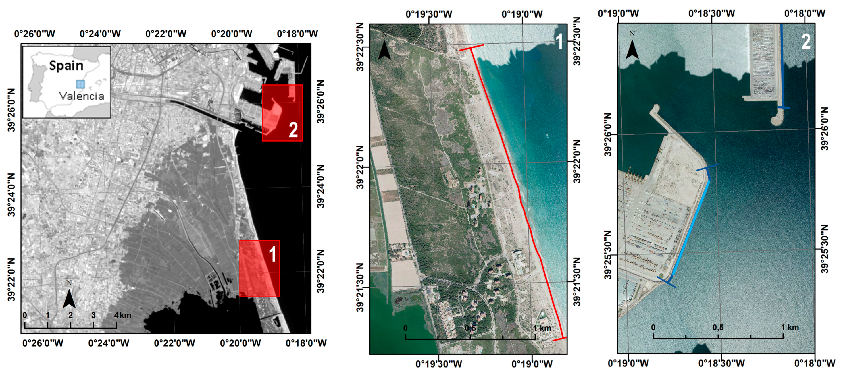
Two specific study areas were chosen: a natural beach located in El Saler (6 km south of Valencia city); and a dike in the port of Valencia (Figure 2). Although the main objective of this work is to assess the accuracy of different shorelines acquired on sandy beaches, it is worthwhile making a comparison with the accuracy obtained for a static coast (such as a port dike). As the two studied areas are quite close to each other, it can be accepted that wave conditions are the same. Therefore, the differences between both zones are exclusively morphological.
The site at El Saler site is a dissipative sandy beach segment 1450 m long. It has a mean slope of 3.65° [22] where we can usually find a small submarine sand bar close to the shore, not always well developed. The beach along the monitoring zone is about 30 m wide and there is a narrow dune line that is covered in poor vegetation.
The 800 m long dike in the southern segment of the Port of Valencia is used as the second study area for assessing shoreline extraction accuracy. The water depth is 11.6 m and there is a sharp line between land and water.

3. Materials and Methods

The proposed workflow enables a sub-pixel shoreline to be obtained from IR bands. It is mainly focused on mid-resolution images, such as those from the Landsat or Sentinel-2 platforms. The evaluation of those shorelines needs another more accurate shoreline measurement to serve as a reference. Moreover, at a certain point, the dynamic reality of some coastal spaces, such as sandy beaches, makes necessary some meta-information about the state of the coastal waves at the time of image acquisition. Meta-information—sea wave conditions—will be used to process the data and understand the results.

3.1. Shoreline Extraction from Mid-Resolution Satellite Imagery

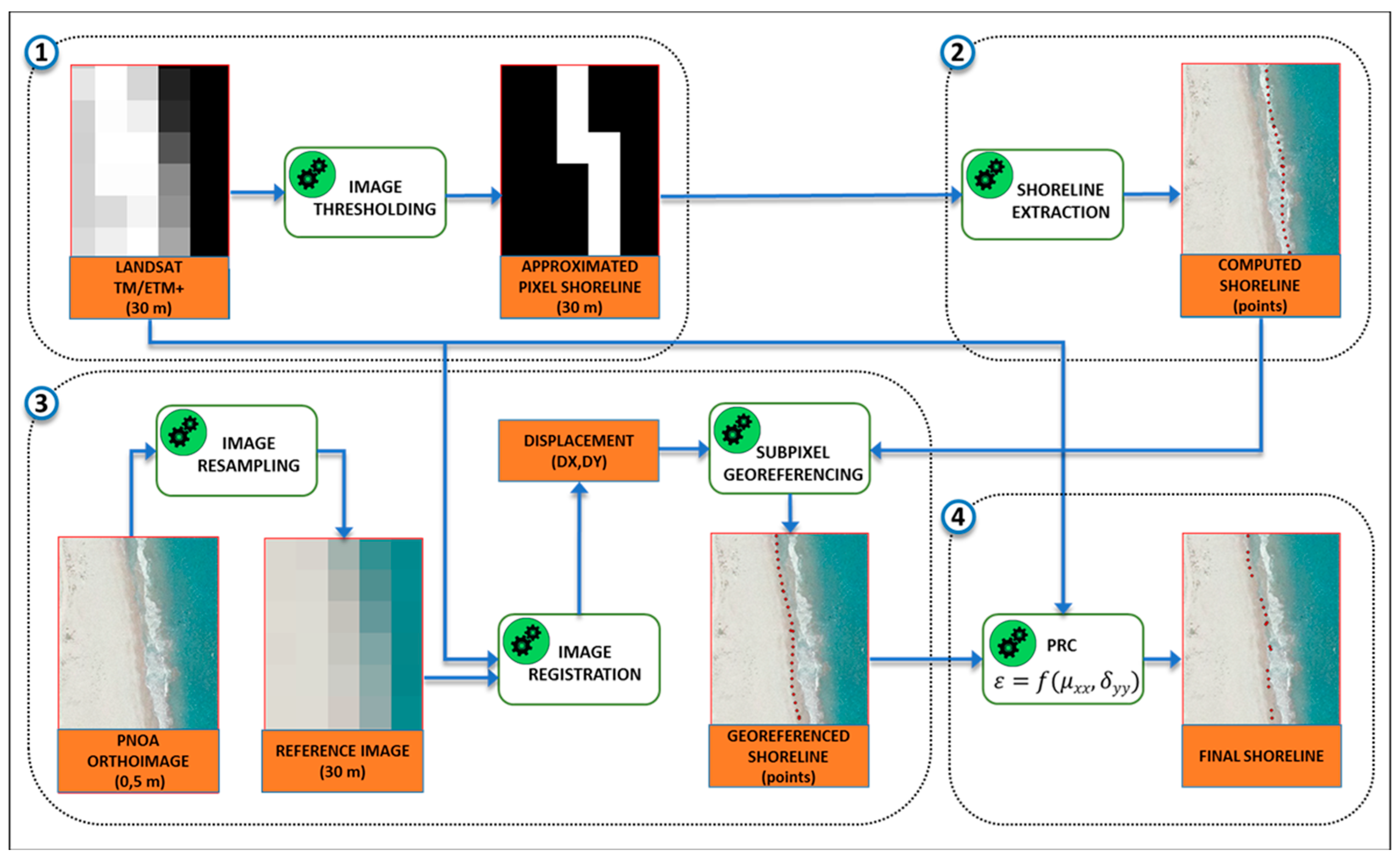
The algorithm is based on the spectral difference that water and land reveal in the infrared bands. Water absorbs most infrared radiation and appears darker than land. This behavior is used to determine, through the next four steps (Figure 3), where the change between these two zones occurs.
(1) Coarse pixel-level shoreline. If the analyzed image contains approximately 50% water and 50% land, its histogram shows two peaks: a narrow and high peak at low digital levels that reveals the main part of the water pixels (low and very homogeneous digital levels); while remaining pixels describe a curve spread along the histogram. By fitting a bi-Gaussian function (that fits one Gaussian curve to each of those peaks/curves), an initial threshold is obtained at the intersection of these two curves. This threshold can be refined manually and serves to binarize the image into land and water. Through a morphological filtering of the binarized image, a pixel level shoreline is obtained.
(2) Sub-pixel shoreline. Based on the work of Almonacid-Caballer, J. [42], a 7 × 7 pixel neighborhood around each coarse shoreline pixel is taken. The digital levels (DL) of each neighborhood are fitted by least squares with a polynomial function, DL = f(x,y). The shoreline is understood as the inflection between land and water. Mathematically, the shoreline is the line in which the Laplacian of that fitted surface is equal to zero. Given that this is done on the polynomial function, the inflection points are not limited to pixel precision. Four points per pixel are used to materialize this mathematical line, and this implies that the points of the shorelines have 7.5, 5, and 2.5 m of spacing for resolutions of 30, 20, and 10 m/pixel respectively. The obtained result is a set of points (x,y) following the inflection line.
(3) Sub-pixel registering process. The available Landsat (7 and 8) and Sentinel-2 images are already georeferenced, so it is expected that no more than small x,y translations are needed to refine the registration between images. The cross correlation (CC) theory works on shifting one or two-dimensional signals and its usage for image registering processes is well known. For this reason, CC is the most suitable algorithm for this case. To reach sub-pixel registering precision, the LUFT has been used. This approach makes use of the Fourier transform through matrix multiplication to upsample only the part of the CC matrix that defines the x,y displacements between two images. In [46] it is proven that using LUFT, for phase correlation, achieves less than 3 m of registering error for Landsat resolution (less than 0.1 pixel). For this paper—given that reference and warp images must be the same size—the same high resolution orthophoto (0.25 m/pixel) has been resampled to 30, 20, and 10 m/pixel of resolution as references for registering all the images.
(4) Polynomial radiometric correction (PRC). In [41,42], it was observed that the heterogeneity of the land pixel values affected the sub-pixel shoreline. A statistical relation was obtained between the heterogeneity of the neighboring pixel function and the geometric error of each point. The mean and standard deviation of each 7 × 7 pixel neighborhood then gave—using a fitted polynomial expression—a displacement in meters to refine the shoreline position located in the middle of that specific neighborhood. The coefficients of the PRC were calculated only for the IR bands of Landsat (5, 7 and 8), but not for Sentinel-2, and in consequence, these images cannot be corrected by PRC.
This workflow has been applied to 21 scenes taken by ETM+ (Landsat 7), OLI (Landsat 8), and MSI (Sentinel-2) sensors between May and November 2016. The images are cloud-free on the studied zone. Landsat 7 gives the images in high (L7H) or low gain (L7L) and this will lead to different considerations. The shorelines have been extracted from all the available near, NIR, and short-wave infrared bands, SWIR 1 and SWIR 2 (Figure 1).
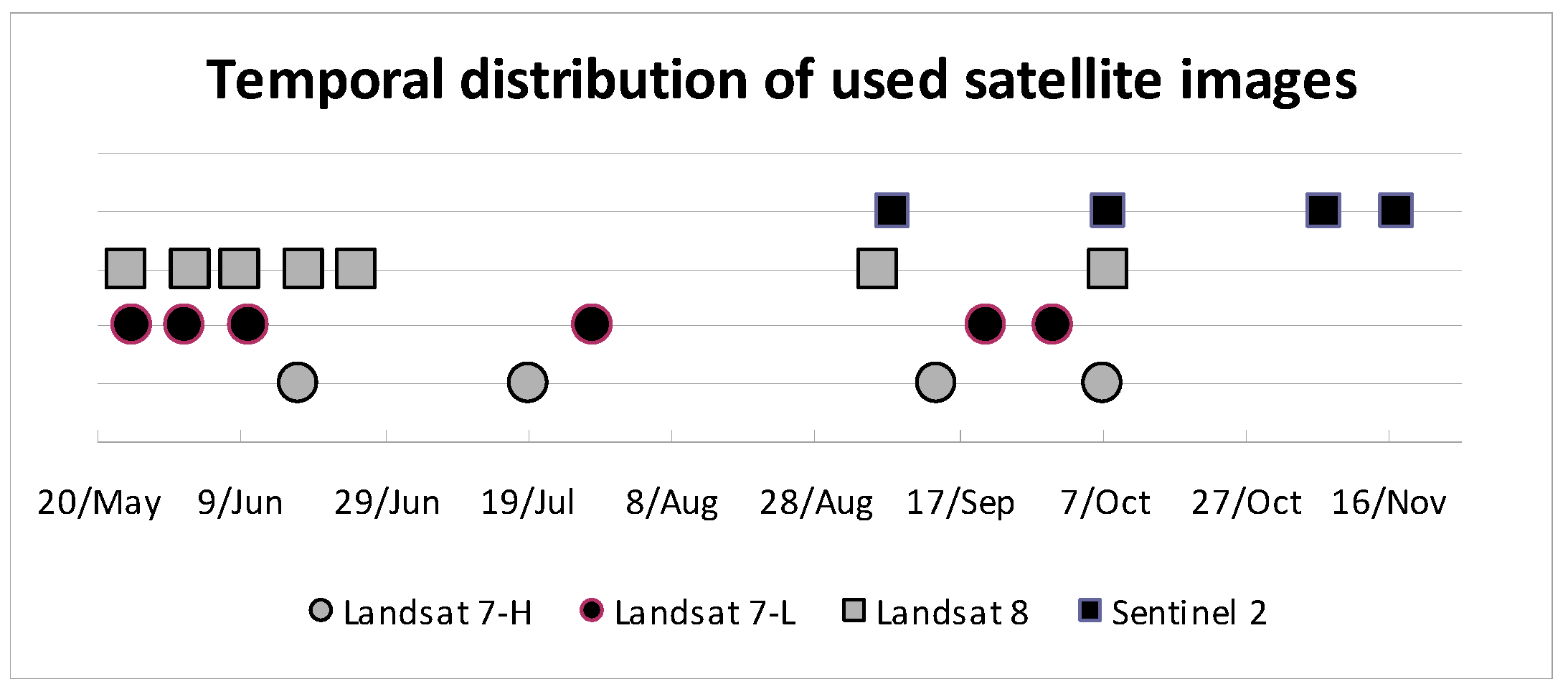
The images were taken around summer 2016 (Figure 4). Most of the Landsat 8 images were taken before the summer, while all the Sentinel-2 images were taken afterwards. Landsat 7 images are more randomly distributed. Analyzing the metadata, the satellite acquisition can be scheduled. The start-stop acquisition time of Landsat 8 and Landsat 7 scenes are 10:43:20–10:43:52 a.m. and 10:45:22–10:45:49 a.m. (UTC time). This interval moves slightly some seconds. The acquisition time for Sentinel is less clear as start-stop acquisition time is 10:54:28–11:07:02 a.m. However, in our beaches, this interval does not imply any tidal effect.

3.2. Reference Data for High-Precision Shorelines

The reference data is crucial. In stable zones, such as ports or seawalls, this is not a problem because the shoreline is not expected to move and the same reference line (in this case, a shoreline digitized in a 0.25 m/pixel orthophotograph) can be used for all the dates. However, this becomes more difficult in unstable zones such as sandy beaches. The shorelines in natural spaces are constantly moving, and this forces the field reference shoreline to be taken at the same time as the satellite image. This frees the shorelines evaluation from any tidal influence.
For this research, the reference shorelines are located on El Saler beach using two methodologies:
(i) Accurate topographic differential GNSS measurements were taken. The water/land boundary is measured by storing coordinates every second with an estimated accuracy of 3–5 cm [52,53].
(ii) A terrestrial photogrammetric perspective was used, and photographs were taken from a building near the reference area. The photos were taken with a digital reflex camera (SONY DSLR-A330) and processed with C-Pro, a coastal projector monitoring system [54]. C-Pro uses GCPs and the horizon constraint to compute the photo resection process. The image can then be projected on a digital elevation model (DEM) or a specific plane. For this paper, the mean sea level (MSL) is obtained instantaneously from the sea level gauge in the port of Valencia, located 8.5 km from the study area. This level has been used to establish the specific elevation value to project each image and resolve the instantaneous shoreline.
Both sets of data are useful in a synergistic way. The terrestrial photographs were taken at the moment when it was expected that the satellites acquired the image—although both moments may not be perfectly coincident. The GPS-shoreline is measured at a moment near the satellite image acquisition. We assume no more than 5 min of delay between the GPS line and the acquisition of the image although each GPS point is taken at the instantaneous land/water limit (which is constantly moving as it is a natural beach). Quantifying the time differences between the photo and the satellite image for each day, we verify that the maximum time delay got is 7 min. Horizontally, the difference between these photographic and GPS-shorelines was measured and a mean error of 0.15 (±1.05) m was obtained. Vertically, comparing the mean elevation value of the GPS-shoreline and the MSL value, we computed a mean difference (|ZMSL − ZGPS-line|) of 0.067 m for all days. In consequence, photographic and GPS shorelines can be considered coincident, while the very small distance between them serves to indicate the magnitude of the natural shoreline movement for each date. Moreover, the terrestrial images offer additional environmental information (for example, the existence of whitewater that can affect the shorelines obtained).
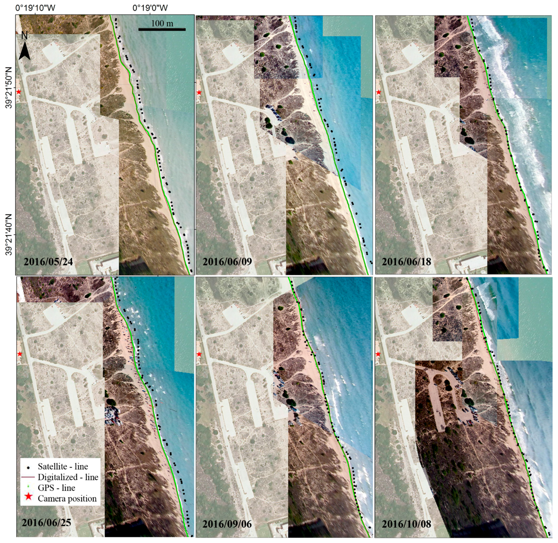
Therefore, for the analysis carried out in the present work, the satellite shorelines were compared with either GPS-shorelines or photo-shorelines. We chose to use the GPS-shoreline except when this information was unavailable—and we then used the digitized shoreline from rectified photos (Figure 5).
In addition, some meta-data (such as significant wave height and peak wave period) was taken from the oceanographic buoy in front of the Port of Valencia.

3.3. Shoreline Accuracy Assessment Methodology

As each sub-pixel shoreline is integrated by points, the distance from those points to their respective reference line is a measure of the error committed. The distances have been stipulated positive seawards and negative landwards. The mean error indicates the bias of the satellite shorelines, while the standard deviation must be understood as the variability of the shoreline at the image registration moment. As mentioned before, the reference line is taken at the time when the satellite is expected to register the scene and so avoids the effect of the tide in our study.

4. Results

Subsequently, the PRC (polynomial radiometric correction) effect and accuracies per date and sensors are shown. Within each, the accuracies on the beach shorelines are compared with those obtained at the dike of the port of Valencia. The differences in the errors observed on the beach compared with those measured at the port dike enable us to recognize the particular effect that the type of shoreline (sandy beach with a gentle slope/rigid shoreline with a steep slope) has on the correct determination of the shoreline position.

4.1. Assessing How PRC Is Working on Sandy Beaches

The original workflow was used on the Landsat series. However, it had to be checked whether the PRC model—fit in seawalls [41,42]—also improves the accuracy of the shoreline positions in other areas. Consequently, the first question to answer is if these models can be extrapolated to natural spaces where different pixel levels and behaviors are expected. To answer this point, PRC-refined and non-refined shorelines were compared on beach and port zones (see Table 1).
A comparison between PRC-corrected and uncorrected shorelines shows that PRC-correction only reduces the bias in 50% of the cases—while it increases standard deviation in all cases. It can be considered that the PRC deduced in previous studies needs to be updated or, at least, cannot be extrapolated directly to other areas. Since there is no PRC available for Sentinel-2 shorelines, the exposed workflow will only be used until step 3 (geo-referenced shorelines).

4.2. Shoreline Errors by Sensor and Date

Although the mean global error and standard deviation of the errors (Table 1) could be good indicators of bias and precision, each shoreline may be affected by instantaneous environmental factors such as wave conditions in the image acquisition moment, coastal slope, and so on. It is necessary to assess how these instantaneous factors on each shoreline. We show results measured for each date and each zone (beach and port).

4.2.1. Errors on Landsat 7 Shorelines

Table 2 and Table 3 show a higher seaward bias for the beach than for the port. It can be seen in the port zone that the deviation values are smaller than the bias. This ensures that the real land/water shorelines are mostly located in the deviation range of each shoreline. The bias is more commonly observed on Landsat 7-H (high gain) than on Landsat 7-L (low gain) shorelines. Given that this happens for the port, the cause may be different types of algorithmic behavior for each type of image.

4.2.2. Landsat 8 Shoreline Errors

The results obtained from Landsat 8 shorelines (Table 4) show that for some dates, in contrast to what happens with Landsat 7 shorelines, the seaward bias is lower than at the port. The shorelines at the port zone are mapped seawards, but within a magnitude of less than 5 m for almost all cases. However, the bias at the beach zones behaves heterogeneously. It is clear that deviations at the port zone are always higher than at the beach zone. This shows that the shoreline extraction at the beach seems to be coherent—but the algorithm detects a shoreline that is naturally different from the port zone.
To understand the environmental factors surrounding the sub-pixel shorelines, a visual analysis is useful. From the information provided in the land photographs taken when the satellite captured the data, we can relate the shoreline positioning errors with the state of the sea. Figure 5 shows six days when Landsat 8 passed over the study area. The figure represents, for each day, the shoreline defined by three different methods: a shoreline acquired by digitizing over the rectified photos; the GPS-shoreline measured in the field; and the Landsat shoreline.
As the resulting errors have already revealed in Table 4, we can now visualize how the Landsat shorelines tend to move seawards. In addition, we can see that for these cases (Landsat 8-band 6) satellite shorelines are unaffected by higher waves—and the shorelines with the greatest error on the beach (9 and 25 June) are generated when images show an apparently calm sea with few ripples (as the figure shows).

4.2.3. Errors of Sentinel-2 Shorelines

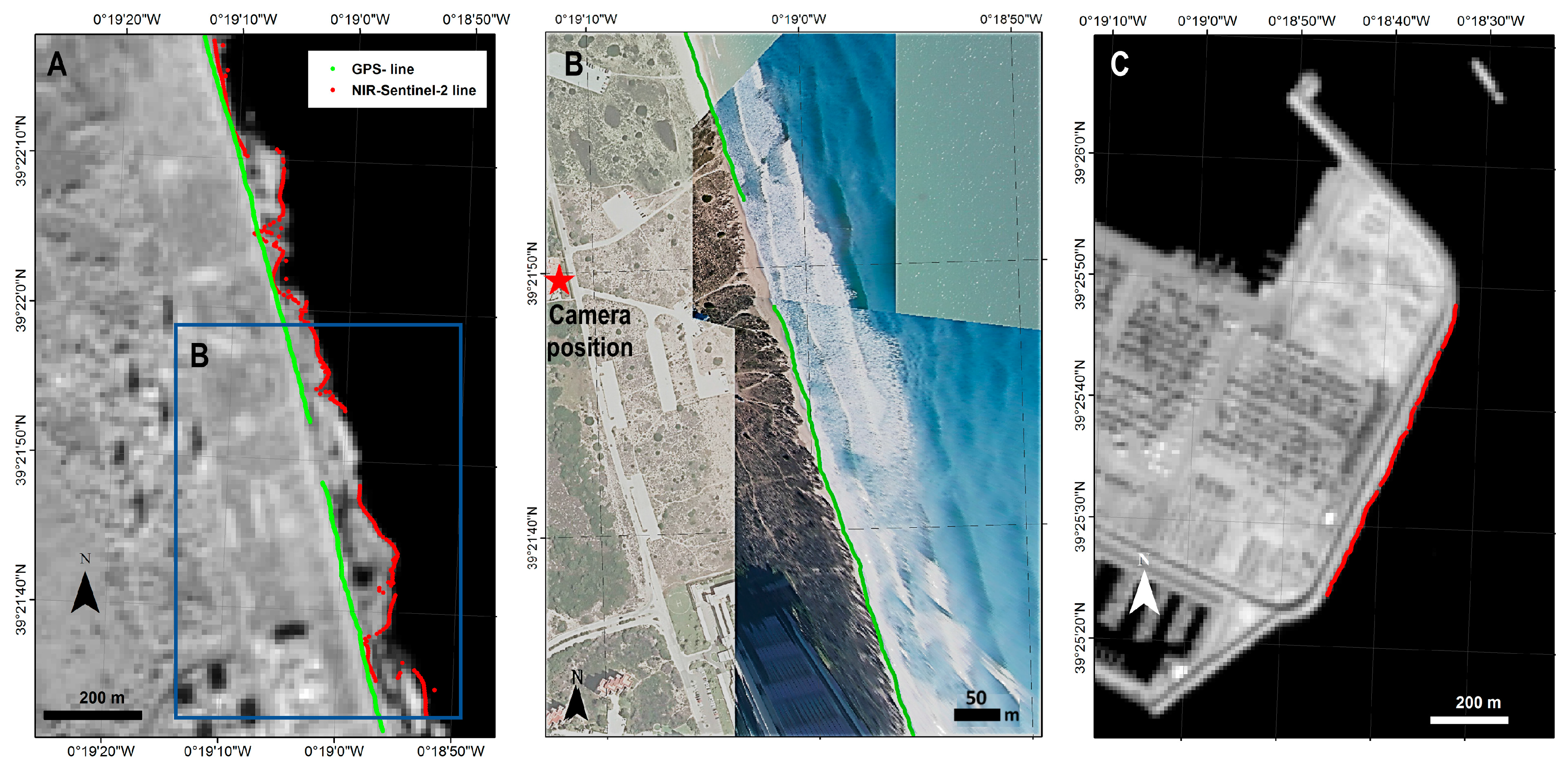
Table 5 contains the statistics for the Sentinel-2 shorelines. The most remarkable aspect in this table are the results for 17 November 2016 where the bias and standard deviation of the NIR band shorelines reach values of around 50 m. Figure 6 shows that the detected lines for those bands are a real boundary between the whitewater patches and the water. This image best shows how whitewater can affect the shorelines. This effect can be considered as an error given that this is not the expected line—but it is a real, natural, and possible line. However, SWIR-band shorelines seem to be more robust when faced by this type of natural confusion.
The Sentinel-2 shorelines show a specific behavior: a landward bias for the SWIR bands. Apart from the whitewater effect, all the shorelines move equivalently landward. It may be seen at the low range of their mean distances. The low standard deviation implies robustness and the fact that the algorithm is probably locating the shoreline, but with a still unexplained bias. The environmental and specific circumstances of each scene must be used again to understand this effect.

5. Discussion

The standard deviations in the port zone resumed in Table 2, Table 3, Table 4 and Table 5 behave similarly to those obtained in previous evaluations on seawalls. Some standard deviations exceptionally reach up to 8.5 m. However, we understand this as occasional behavior, while the standard deviation average is up to 6.08 m. The worst standard deviation is at seawalls when analyzing a large set of images [42].
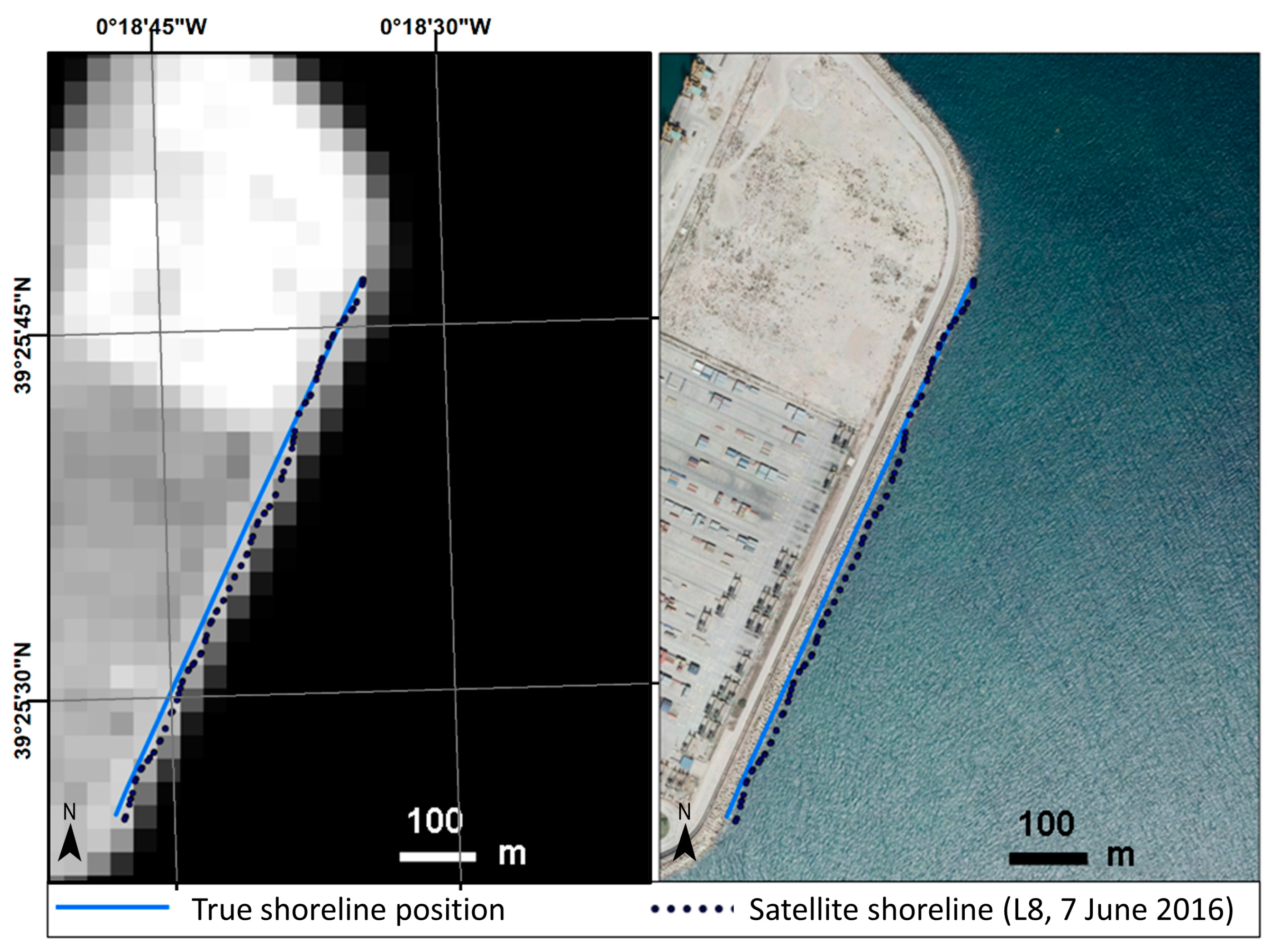
The first question, also related with those exceptional deviations, is related with the PRC—the last step of the workflow. Pardo-Pascual et al. [41] and Almonacid-Caballer [42] observed that the digital levels of the pixels neighboring each shoreline point influenced its position. It was observed that brighter land pixels forced the shoreline to move landwards. From that point, a mathematical expression could be fitted to obtain the bias (error compared with a reference) of each point—depending on the mean and standard deviations of neighboring pixel values. That adjustment leads to the PRC expressions (different for each Landsat). It has been demonstrated in the previous sections that this PRC cannot be extrapolated to beaches (or an update would be necessary). Consequently, PRC has not been applied here and the effect of the bias due to reflectance may be observed (Figure 7).
In the northern zone of Figure 7, a brighter segment moves the shoreline points landwards, while darker pixels in the southern zone move them seawards. In each of these parts, the points move as a block, not randomly. If each were analyzed separately, a different bias but very similar deviation would be found. As all the port zone is analyzed together, a higher standard deviation is obtained. In contrast to the port, there are no differentiating behaviors at the beach where the land pixel values remain more constant. Therefore, the standard deviation is larger at the port zone than at the beach (Table 2, Table 3, Table 4 and Table 5).
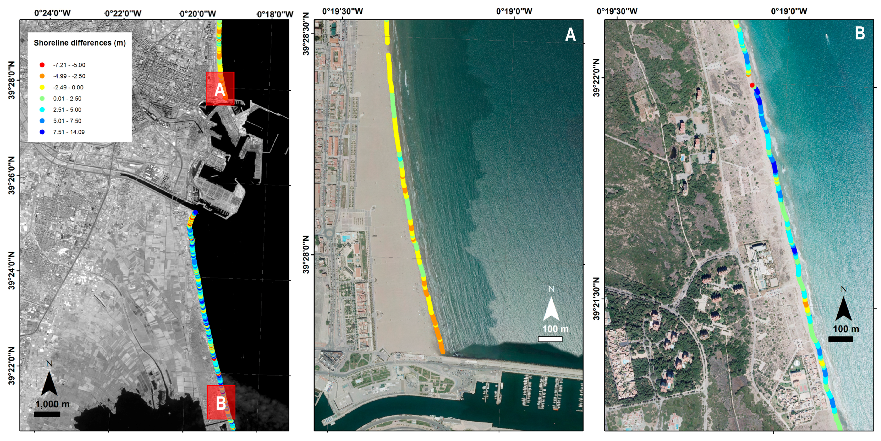
A comparative analysis between the shorelines obtained from Sentinel-2 and Landsat 8 images on 8 October 2016 was carried out to discover how surface brightness variations affect the position of the shoreline. To achieve this, two coastal segments were analyzed: one 3.5 km long and located to the north of the port of Valencia, and another measuring 8.5 km to the south (see Figure 8).
An initial shoreline was obtained using a kernel of 7 × 7 pixels. This kernel covers a wider area for Landsat 8 than Sentinel-2 due to the pixel resolutions. The comparison between both resulting shorelines (Landsat 8 compared to Sentinel-2) shows that the Landsat shoreline bias is 2.17 ± 3.38 m seawards on average. However, Figure 8 shows a landwards bias at the site north of the port (Figure 8A) and seawards at the southern site (Figure 8B). The main difference between both zones is the beach width. The northern site is a very wide beach, and consequently, the analyzed kernel will contain very bright pixels corresponding to the beach sand. The beach at the southern site is about 30 m wide with a dune strip covered in spots of vegetation. Given that Landsat 8 covers a wider area of analysis than Sentinel-2, it captures more vegetation surface (darker than the beach response). This fact supports the idea that when a darker neighborhood is analyzed, it displaces the shoreline offshore.
A second analysis was carried out to examine a neighborhood that covers the same zone (swath) for both types of satellite images. Thus, a 7 × 7 pixel kernel was used for Sentinel 2 images (covering a 140 m swath) and 5 × 5 pixel for Landsat 8 images (covering 150 m). The shoreline differences in this case decrease to −0.75 ± 2.5 m and reinforce the idea that differing pixel brightnesses in the terrestrial zone influence the location of the shoreline. Although Landsat 8 and Sentinel-2 have different relative spectral response functions (RSRF) [55], the small differences found between their shorelines suggest that they are equivalent and can be used together in subsequent analyzes.
Other aspects may affect shoreline extraction. One of these aspects may be the resampling with which Landsat and Sentinel-2 pixels are interpolated during the terrain correction. Cubic convolution is currently used by USGS and ESA, and as a result, each pixel may be ‘contaminated’ by neighboring pixels. However, using other interpolation methods such as nearest neighbor, produces worse shorelines because they cause unrealistic jumps and toothed forms.
The distances of the satellite shoreline points compared with their references at the beach zone show low standard deviations. This means that each shoreline moves as a block from the reference. The reference shoreline is representing the land-water boundary, but the satellite sub-pixel shoreline is not identifying exactly the same line (depending on the environmental situation). Table 6 joins the mean errors (by date) and some variables of the state of the sea, such as significant wave height (H1/3), peak wave period (Tp), and the run-up value (R2%) calculated by the [56] Stockdon formula:
R 2 % = 1.1 ( 0.35 β f ( H L ) 1 / 2 + ( H L ( 0.563 β f 2 + 0.004 ) ) 1 / 2 2 )
where the wavelength has been calculated by L = (gTp2)/2π and the slope (βf) has been estimated as a constant, 0.063. The mean slope value of the zone is deduced in [22].
One of the most disturbance-causing effects in the beach zones is the presence of whitewater. A clear whitewater patch is seen in the Sentinel-2 scene of 17 November 2016 (Figure 6). The highest wave height of the series occurs on this day (Table 6 and Figure 6B). The worst effect takes place in the NIR band. In this case, the workflow deduces the shoreline at the whitewater-water boundary, but this does not happen with the SWIR bands. Nevertheless, the terrestrial photographs (taken at the same time as the satellite passes overhead) show other days with whitewater patches next to the beach, and this does not seem to cause much effect on the algorithm (Figure 5). The workflow may register different boundaries depending on the way the whitewater is detected in each band, and the size of the whitewater patch. It was proven via field measurements [57,58,59] that the reflectance of the whitewater decreases for larger wavelengths. This implies NIR bands are more sensitive to whitewater than SWIR bands—as was observed in this paper.
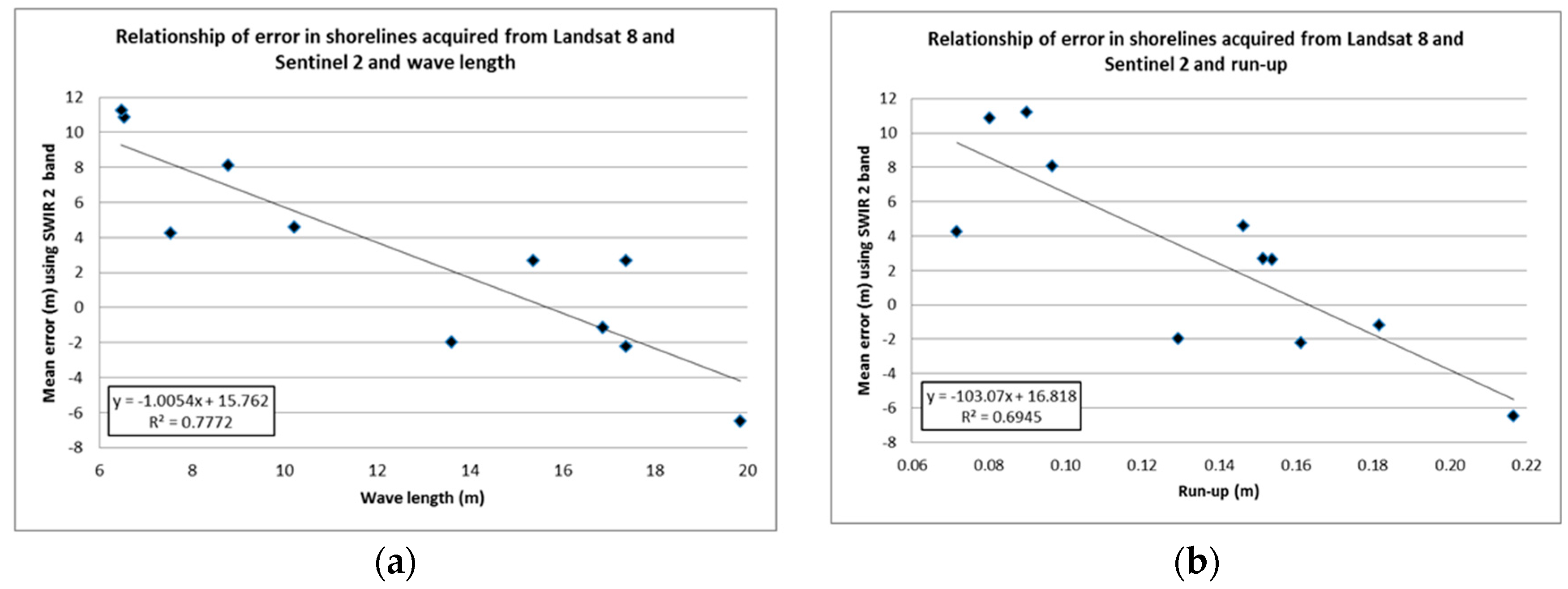
The characteristics of the waves are environmental variables that may potentially affect shoreline accuracy. Figure 9a shows a relation (R2 = 0.77) between Sentinel-2 and Landsat 8 shoreline bias (with SWIR-2 shorelines) with the sea wavelength. Larger wavelengths move the shorelines landward, something that sounds natural given that larger wavelengths also move the wet zone landward. This could be related with the run-up—however, the correlation (Figure 9b) with the shoreline bias decreases slightly (R2 = 0.69). This may be affected by the run-up calculation following the Stockdon equation (where a single slope value is used implying a simplification of reality). These correlations are also high (R2 = 0.77 for wavelength and R2 = 0.68 for the run-up) when analyzing SWIR-1 shorelines. Even though these are clear correlations, causal factors cannot be specified. The run-up may lead to wide wet zones, while the movement of the waves may darken the radiometric response next to the beach. This correlation between bias and sea wavelength does not appear clearly on Landsat 7 shorelines, probably due to the different spectral window for Landsat 8 and Sentinel-2.
Finally, Table 7 sums up the mean bias, standard deviation and RMSE of the errors for the whole set of shorelines (distinguishing between sensors and zones). Only the SWIR bands that work best are shown (the NIR band may be greatly affected by whitewater). The mean values and standard deviations of each shoreline have been weighted with their own standard deviations in order not to lose the real uncertainties. As can be seen, we have joined statistics of Landsat 8 and Sentinel-2. The equivalent results of their shorelines taken on the same day, their similar spectral SWIR windows, and how they similarly correlate with the sea wavelength, mean that we may accept that both are showing the same reality.
For the three sets of images used (L7H, L7L and Landsat 8 + Sentinel-2) it can be observed that mean seaward bias is greater at the beach than at the port. The Landsat 8 + Sentinel-2 set is the least biased and this is related with sea wave conditions. The differing behavior among the three sets may be due to the different spectral resolution at the IR bands (differences between ETM+ and OLI or MSI sensors), or due to their respective radiometric resolution (8 or 12 bits). Although both bands offer similar accuracy, the SWIR 1 band has less bias and deviation at the beach than at the port separately for each date.
It is important to note that the achieved bias, precision and accuracy are in line with those obtained in other recent studies. In [60], Progreso beach (8 km long) in Yucatán (Mexico) was analyzed by extracting the shoreline from the NIR band of a Spot 5 satellite image (10 m/pixel). The shoreline was obtained after georeferencing and binarizing the image with a non-supervised classification, and is compared with a GPS-shoreline. As a result, the Spot shoreline bias is 5.6 ± 1.37 m seawards and up to 7 m.
Working with Landsat 5 and 7 data, [22] estimated a mean annual shoreline position that was slightly biased seawards by around 3 to 5 m. It is worth noting that this work applied a previous image geo-referenced correction at sub-pixel level using the LUFT method [47,48].
In [38] the shoreline position is analyzed at Narrabeen-Collaroy beach in Australia (as obtained from a complete Landsat set between 1987 and 2016). The reference data consisted of five topographic profiles along the entire shoreline. Each profile gave a shoreline point which is compared with the respective Landsat shoreline intersection. The authors reached an overall mean bias close to 0 but with an RMSE (root mean squared error) of 10 m. No image registering process was mentioned and this would probably have enabled better results (as is shown in [46]). Another factor is that the RMSE results from several profiles and time series imply an effect for the instantaneous position of the waves. Dissipative wave behavior and the difference in spectral responses due to the water depth were also commented on, as well as the difficulties in evaluating natural beaches.
Consequently, despite being affected by all the analyzed factors, the sub-pixel shorelines obtained in the present paper behave equally, or better, than in other studies. However, each individual shoreline of dynamic spaces showed higher deviations and, in agreement with the references, may be affected by the described environmental factors, and perhaps by other factors still undiscovered. More assorted analyses in other beaches, and under differing environmental conditions, would be useful for a reevaluation.
6. Conclusions

The accuracy of sub-pixel shorelines on natural beaches obtained by the proposed workflow was analyzed. It must be first mentioned that the original workflow [41,42] was slightly modified. Images and shorelines were registered and extracted at sub-pixel level—but not corrected by the influence of various bright land pixels along the shoreline. To assess them, a comparison for land/water shorelines (measured via terrestrial photogrammetry and GNSS) was made. This comparison confirms that satellite shorelines define the land/water boundary with sub-pixel accuracy (Table 7). The main conclusions are:
  • SWIR-1 bands, in all satellite sensor systems, offer the most accurate and robust sub-pixel shorelines on our study area. This result is a starting point that can be extrapolated to other similar areas and studies.
  • Shorelines obtained from the NIR band have usually been accurate, but have shown to be more affected by whitewater and foam.
  • Shorelines extracted from Landsat 8 and Sentinel 2 show similar disturbances for environmental factors, brightness of the land zone, and wavelength of the incident waves.
  • The brightness of the land pixels surrounding the shoreline seems to affect the detected shoreline moving it landwards as the brightness of the pixels increase. This behavior appears clearer at the port area. It was seen in previous publications although modelling it has not been possible.
  • A relationship between the bias of the shorelines—obtained from the SWIR-1 band of Landsat 8 and Sentinel-2—and the wavelengths of the sea waves is found. It suggests, even with the scarcity of data, that the state of the sea affects the extracted sub-pixel shorelines.

Acknowledgements

The authors appreciate the financial support provided by the Spanish Ministry of Economy and Competitiveness in the framework of project CGL2015-69906-R. This study is part of the Ph.D. dissertation of the second author, which is supported by a grant from the Spanish Ministry of Education, Culture and Sports (I+D+i 2013–2016). The authors are extremely grateful to different reviewers and editors of this work because their observations and suggestions have improved the final article a lot.

Author Contributions

Josep E. Pardo-Pascual, Elena Sánchez-García, Jaime Almonacid-Caballer and Ángel Balaguer-Beser conceived the work, designed the tests and analyzed the results. Jesús M. Palomar-Vázquez, Josep E. Pardo-Pascual, Jaime Almonacid-Caballer and Alfonso Fernández-Sarría obtained the shorelines from Landsat and Sentinel 2 images while Enrique Priego de los Santos and Elena Sánchez-García acquired the field data. All the authors have collaborated on the final redaction of the paper.

Conflicts of Interest

The authors declare no conflicts of interest.

References

  1. Boak, E.H.; Turner, I.L. Shoreline definition and detection: A review. J. Coast. Res. 2005, 21, 688–703. [Google Scholar] [CrossRef]
  2. Ford, M. Shoreline changes interpreted from multi-temporal aerial photographs and high resolution satellite images: Wotje Atoll, Marshall Islands. Remote Sens. Environ. 2013, 135, 130–140. [Google Scholar] [CrossRef]
  3. Jones, B.M.; Arp, C.D.; Jorgenson, M.T.; Hinkel, K.M.; Schmutz, J.A.; Flint, P.L. Increase in the rate and uniformity of shoreline erosion in Arctic Alaska. Geophy. Res. Lett. 2009, 36. [Google Scholar] [CrossRef]
  4. Morton, R.A.; Miller, T.L.; Moore, L.J. National Assessment of Shoreline Change, Part 1: Historical Shoreline Changes and Associated Coastal Land Loss Along the U.S. Gulf of Mexico. U.S. Geological Survey Open-file report 2004–1043. Available online: https://pubs.usgs.gov/of/2004/1043/ofr-2004-1043.pdf (accessed on 21 February 2018).
  5. Stockdon, H.F.; Sallenger, A.H.; List, J.H.; Holman, R.A. Estimation of the shoreline position and change using airborne topographic lidar data. J. Coast. Res. 2002, 18, 502–513. [Google Scholar]
  6. Ruggiero, P.; Kaminsky, G.M.; Gelfenbaum, G.; Voigt, B. Seasonal to interannual morphodynamics along a high-energy dissipative littoral cell. J. Coast. Res. 2005, 21, 553–578. [Google Scholar] [CrossRef]
  7. Moore, L.J.; Ruggiero, P.; List, J.H. Comparing mean high water and high water line shorelines: Should proxy-datum offsets be incorporated into shoreline change analysis? J. Coast. Res. 2006, 22, 894–905. [Google Scholar] [CrossRef]
  8. List, J.H.; Farris, A.S.; Sullivan, C. Reversing storm hotspots on sandy beaches: Spatial and temporal characteristics. Mar. Geol. 2006, 226, 261–279. [Google Scholar] [CrossRef]
  9. Pardo-Pascual, J.E.; García-Asenjo, L.; Palomar-Vázquez, J.; Garrigues-Talens, P. New methods and tools to analyze beach-dune system evolution using a Real-Time Kinematic Global Positioning System and Geographic Information Systems. J. Coast. Res. 2005, 49, 34–39. [Google Scholar]
  10. Psuty, N.P.; Silvera, T.M. Tracking coastal geomorphological change: An application of protocols to collect geotemporal data sets at the national level in the US. J. Coast. Res. 2011, 64, 1253–1257. [Google Scholar]
  11. White, S.A.; Wang, Y. Utilizing DEMs derived from LIDAR data to analyze morphologic change in the North Carolina shoreline. Remote Sens. Environ. 2003, 85, 39–47. [Google Scholar] [CrossRef]
  12. Shrestha, R.L.; Carter, W.E.; Sartori, M.; Luzum, B.J.; Slatton, K.C. Airborne laser swath mapping: Quantifying changes in sandy beaches over time scales of weeks to years. ISPRS J. Photogramm. Remote Sens. 2005, 59, 222–232. [Google Scholar] [CrossRef]
  13. Gares, P.; Wang, Y.; White, S.A. Using LIDAR to monitor a beach nourishment project at Wrightsville Beach, North Carolina, USA. J. Coast. Res. 2006, 22, 1206–1219. [Google Scholar] [CrossRef]
  14. Smeeckaert, J.; Mallet, C.; David, N.; Chehata, N.; Ferraz, A. Large-scale classification of water areas using airborne topographic lidar data. Remote Sens. Environ. 2013, 138, 134–148. [Google Scholar] [CrossRef]
  15. Hobbs, P.; Gibson, A.; Jones, L.; Poulton, C.; Jenkins, G.; Pearson, S.; Freeborough, K. Monitoring coastal change using terrestrial LiDAR. In Elevation Models for Geoscience; Fleming, C., Marsh, S., Giles, J.M., Eds.; Geological Society of London: London, UK, 2010. [Google Scholar]
  16. Holman, R.; Stanley, J. The history and technical capabilities of Argus. Coast. Eng. 2007, 54, 477–491. [Google Scholar] [CrossRef]
  17. Davidson, M.; Van Koningsveld, M.; de Kruif, A.; Rawson, J.; Holman, R.; Lamberti, A.; Medina, R.; Kroon, A.; Aarninkhof, S. The CoastView project: Developing video-derived Coastal State Indicators in support of coastal zone management. Coast. Eng. 2007, 54, 463–475. [Google Scholar] [CrossRef]
  18. Archetti, R.; Schiaffi, C.F.; Ferrari, M.; Brignone, M.; Rihouey, D. Video systems for coastal monitoring. In Beach Erosion Monitoring Beachmed-e/OpTIMAL Project; Pranzini, E., Wetzel, L., Eds.; Nuova Grafica Fiorentina: Florence, Italy, 2008; pp. 101–109. [Google Scholar]
  19. Vandebroek, E.; Lindenbergh, R.; van Leijen, F.; de Schipper, M.; de Vries, S.; Hanssen, R. Semi-automated monitoring of a mega-scale beach nourishment using high-resolution terrasar-x satellite data. Remote Sens. 2017, 9, 653. [Google Scholar] [CrossRef]
  20. Maiti, S.; Bhattacharya, A.K. Shoreline change analysis and its application to prediction: A remote sensing and statistics based approach. Mar. Geol. 2009, 257, 11–23. [Google Scholar] [CrossRef]
  21. Mann, T.; Westphal, H. Assessing long-term changes in the beach width of reef islands based on temporally fragmented remote sensing data. Remote Sens. 2014, 6, 6961–6987. [Google Scholar] [CrossRef]
  22. Almonacid-Caballer, J.; Sánchez-García, E.; Pardo-Pascual, J.E.; Balaguer-Beser, A.A.; Palomar-Vázquez, J. Evaluation of annual mean shoreline position deduced from Landsat imagery as a mid-term coastal evolution indicator. Mar. Geol. 2016, 372, 79–88. [Google Scholar] [CrossRef]
  23. Li, J.; Roy, D.P. A global analysis of Sentinel-2a, Sentinel-2b and Landsat 8 data revisit intervals and implications for terrestrial monitoring. Remote Sens. 2017, 9, 902. [Google Scholar] [CrossRef]
  24. Ryu, J.H.; Won, J.S.; Min, K.D. Waterline extraction from Landsat TM data in a tidal flat: A case study in Gomso Bay, Korea. Remote Sens. Environ. 2002, 83, 442–456. [Google Scholar] [CrossRef]
  25. Ekercin, S. Shoreline change assessment at the Aegean Sea Coasts in Turkey using multitemporal Landsat imagery. J. Coast. Res. 2007, 23, 691–698. [Google Scholar] [CrossRef]
  26. Yu, K.; Hu, C.; Muller-Karger, F.; Lu, D.; Soto, I. Shoreline changes in west-central Florida between 1987 and 2008 from Landsat observations. Int. J. Remote Sens. 2011, 32, 8299–8313. [Google Scholar] [CrossRef]
  27. Quang Tuan, N.; Cong Tin, H.; Quang Doc, L.; Anh Tuan, T. Historical monitoring of shoreline changes in the Cua Dai Estuary, Central Vietnam using multi-temporal remote sensing data. Geosciences 2017, 7, 72. [Google Scholar] [CrossRef]
  28. Feyisa, G.L.; Meilby, H.; Fensholt, R.; Proud, S.R. Automated water extraction index: A new technique for surface water mapping using Landsat imagery. Remote Sens. Environ. 2014, 140, 23–35. [Google Scholar] [CrossRef]
  29. Ouma, Y.O.; Tateishi, R. A water index for rapid mapping of shoreline changes of five East African Rift Valley lakes: An empirical analysis using Landsat TM and ETM+ data. Int. J. Remote Sens. 2006, 27, 3153–3181. [Google Scholar] [CrossRef]
  30. Hui, F.; Xu, B.; Huang, H.; Yu, Q.; Gong, P. Modelling spatial–temporal change of Poyang Lake using multitemporal Landsat imagery. Int. J. Remote Sens. 2008, 29, 5767–5784. [Google Scholar] [CrossRef]
  31. Choung, Y.J.; Jo, M.H. Shoreline change assessment for various types of coasts using multi-temporal Landsat imagery of the east coast of South Korea. Remote Sens. Lett. 2015, 7, 91–100. [Google Scholar] [CrossRef]
  32. Foody, G.M.; Muslim, A.M.; Atkinson, P.M. Super-resolution mapping of the waterline from remotely sensed data. Int. J. Remote Sens. 2005, 26, 5381–5392. [Google Scholar] [CrossRef]
  33. Muslim, A.M.; Foody, G.M.; Atkinson, P.M. Localized soft classification for super resolution mapping of the shoreline. Int. J. Remote Sens. 2006, 27, 2271–2285. [Google Scholar] [CrossRef]
  34. Liu, Q.; Trinder, J.; Turner, I. A comparison of sub-pixel mapping methods for coastal areas. ISPRS Ann. 2016, 3, 67–74. [Google Scholar]
  35. Li, L.; Chen, Y.; Xu, T.; Liu, R.; Shi, K.; Huang, C. Super-resolution mapping of wetland inundation from remote sensing imagery based on integration of back-propagation neural network and genetic algorithm. Remote Sens. Environ. 2015, 164, 142–154. [Google Scholar] [CrossRef]
  36. Li, X.; Ling, F.; Foody, G.M.; Du, Y. Improving super-resolution mapping through combining multiple super-resolution land-cover maps. Int. J. Remote Sens. 2016, 37, 2415–2432. [Google Scholar] [CrossRef]
  37. Shi, Z.; Li, P.; Jin, H.; Tian, Y.; Chen, Y.; Zhang, X. Improving super-resolution mapping by combining multiple realizations obtained using the indicator-geostatistics based method. Remote Sens. 2017, 9, 773. [Google Scholar] [CrossRef]
  38. Liu, Q.; Trinder, J.; Turner, I.L. Automatic super-resolution shoreline change monitoring using Landsat archival data: A case study at Narrabeen–Collaroy Beach, Australia. J. Appl. Remote Sens. 2017, 11. [Google Scholar] [CrossRef]
  39. Cipolletti, M.P.; Delrieux, C.A.; Perillo, G.M.E.; Piccolo, M.C. Superresolution border segmentation and measurement in remote sensing images. Comput. Geosci. 2012, 40, 87–96. [Google Scholar] [CrossRef]
  40. Ruiz, L.A.; Pardo, J.E.; Almonacid, J.; Rodríguez, B. Coastline automated detection and multi-resolution evaluation using satellite images. In Proceedings of the Coastal Zone 7, Portland, OR, USA, 22–26 July 2007. [Google Scholar]
  41. Pardo-Pascual, J.E.; Almonacid-Caballer, J.; Ruiz, L.A.; Palomar-Vázquez, J. Automatic extraction of shorelines from Landsat TM and ETM multi-temporal images with sub-pixel precision. Remote Sens. Environ. 2012, 123, 1–11. [Google Scholar] [CrossRef]
  42. Almonacid-Caballer, J. Extraction of Shorelines with Sub-Pixel Precision from Landsat Images (TM, ETM+, OLI) [Obtención de Lineas de Costa con Precisión Sub-Pixel a Partir de Imágenes Landsat (TM, ETM+ y OLI)]. Ph.D. Thesis, Universitat Politècnica de València, Valencia, Spain, 10 October 2014. [Google Scholar]
  43. Iron, J.R.; Dwyer, J.L.; Barsi, J.A. The next Landsat satellite: The Landsat Data Continuity Mission. Remote Sens. Environ. 2012, 122, 11–21. [Google Scholar] [CrossRef]
  44. Roy, D.P.; Wulder, M.A.; Loveland, T.R.; Woodcock, C.E.; Allen, R.G.; Anderson, M.C.; Helder, D.; Irons, J.R.; Johnson, D.M.; Kennedy, R.; et al. Landsat-8: Science and product vision for terrestrial global change research. Remote Sens. Environ. 2014, 145, 154–172. [Google Scholar] [CrossRef]
  45. Clerc, S.; MPC Team. S2 MPC. Data Quality Report, 2017, Reference S2-PDGS-MPC-DQR. Available online: https://sentinels.copernicus.eu/documents/247904/685211/Sentinel-2-Data-Quality-Report (accessed on 21 February 2018).
  46. Almonacid-Caballer, J.; Pardo-Pascual, J.E.; Ruiz, L.A. Evaluating fourier cross-correlation sub-pixel registration in landsat images. Remote Sens. 2017, 9, 1051. [Google Scholar] [CrossRef]
  47. Guizar-Sicairos, M.; Thurman, S.T.; Fienup, J.R. Efficient sub-pixel image registration algorithms. Opt. Lett. 2008, 3, 156–158. [Google Scholar] [CrossRef]
  48. Wang, C.L.; Zhao, C.X.; Yang, J.Y. Local upsampling Fourier transform for high accuracy image rotation estimation. Adv. Mater. Res. 2011, 268–270, 1488–1593. [Google Scholar] [CrossRef]
  49. Pardo-Pascual, J.E.; Almonacid-Caballer, J.; Ruiz, L.A.; Palomar-Vázquez, J.; Rodrigo-Alemany, R. Evaluation of storm impact on sandy beaches of the Gulf of Valencia using Landsat imagery. Geomorphology 2014, 214, 334–401. [Google Scholar] [CrossRef]
  50. Sánchez-García, E.; Pardo-Pascual, J.E.; Balaguer-Beser, A.; Almonacid-Caballer, J. Analysis of the shoreline position extracted from Landsat TM and ETM+ imagery. ISPRS Arch. 2015, XL-7/W3, 991–998. [Google Scholar]
  51. REDMAR (Red de Mareógrafos de Puertos del Estado). Resumen de los parámetros relacionados con el nivel del mar y la marea que afectan a las condiciones de diseño y explotación portuaria. Puerto de Valencia¸ Dirección Técnica Puertos del Estado. 2014. Available online: http://calipso.puertos.es/BD/informes/globales/GLOB_2_3_3651.pdf (accessed on 21 February 2018).
  52. Prochniewicz, D.; Szpunar, R.; Walo, J. A new study of describing the reliability of GNSS Network RTK positioning with the use of quality indicators. Meas. Sci. Technol. 2016, 28. [Google Scholar] [CrossRef]
  53. Paziewski, J.; Wielgosz, P. Investigation of some selected strategies for multi-GNSS instantaneous RTK positioning. Adv. Space Res. 2017, 59, 12–23. [Google Scholar] [CrossRef]
  54. Sánchez-García, E.; Balaguer-Beser, A.; Pardo-Pascual, J.E. C-Pro: A Coastal Projector monitoring system using terrestrial photogrammetry with a geometric horizon constraint. ISPRS J. Photogramm. Remote Sens. 2017, 128, 255–273. [Google Scholar] [CrossRef]
  55. Mandanici, E.; Bitelli, G. Preliminary comparison of sentinel-2 and landsat 8 imagery for a combined use. Remote Sens. 2016, 8, 1014. [Google Scholar] [CrossRef]
  56. Stockdon, H.F.; Holman, R.A.; Howd, P.A.; Sallenger, A.H. Empirical parameterization of setup, swash, and runup. Coast. Eng. 2006, 53, 573–588. [Google Scholar] [CrossRef]
  57. Whitlock, C.H.; Barlett, D.S.; Gurganus, E.A. Sea foam reflectance and optimum wavelength for remote sensing of ocean aerosols. Geophy. Res. Lett. 1982, 9, 719–722. [Google Scholar] [CrossRef]
  58. Koepke, P. Effective reflectance of oceanic whitecaps. Appl. Opt. 1984, 23, 1816–1824. [Google Scholar] [CrossRef] [PubMed]
  59. Frouin, R.M.; Schwindling, M.; Deschamps, P.Y. Spectral reflectance of sea foam in the visible and near infrared: In situ measurements and remote sensing implications. J. Geophys. Res. 1996, 101, 14361–14371. [Google Scholar] [CrossRef]
  60. García-Rubio, G.; Huntley, D.; Russell, P. Evaluating shoreline identification using optical satellite images. Mar. Geol. 2015, 359, 96–105. [Google Scholar] [CrossRef]
Figure 1. Spatial resolution and spectral range occupied by Landsat (7 and 8) and Sentinel-2 bands in the optical spectral region.
Remotesensing 10 00326 g001
Figure 2. Zones chosen for quality assessment of the extracted shorelines. (1) The sandy beach at El Saler, and (2) part of a dike in the port of Valencia.
Remotesensing 10 00326 g002
Figure 3. Current workflow of the process.
Remotesensing 10 00326 g003
Figure 4. Temporal distribution of the 21 scenes acquired from three satellite platforms. Note that on 8 October the study zones were registered both by Landsat 8 and Sentinel-2 with only 18 min of difference.
Remotesensing 10 00326 g004
Figure 5. The same orthophoto is used in the six images simply as a base map. On these images, the projection of six terrestrial images for El Saler beach is shown. Their projection is made at the mean sea level value for each date. Note that the camera is not fixed, and the different extension covered by the photos is a consequence of the hand-selected region projected. Each map shows the GPS-line, the digitalized-line (almost coincident between them) and the satellite shoreline.
Remotesensing 10 00326 g005
Figure 6. Sections of: (A) El Saler beach and (C) the port zone in a 10 m pixel size image in the NIR band (band 8) of Sentinel-2 acquired on 17 November 2016; (B) shows two photos for this day rectified by C-Pro over an orthophoto taken from 2010 PNOA sources (used simply as a base map). The reference shoreline position acquired using differential GNSS appears in green, and the automatically detected satellite shoreline in red. (A) shows how the shoreline has been erroneously detected as the whitewater border. In the case of the port (C), where there is no whitewater due to the greater water depth, and the shorelines are correctly detected.
Remotesensing 10 00326 g006
Figure 7. The blue line is the high-resolution mapped shoreline and the dark blue points represent the sub-pixel shoreline. The base image on the left is Landsat 8. The base image on the right is the 2010 PNOA orthophoto. Higher and lower reflectance pushes the shorelines landwards or seawards respectively.
Remotesensing 10 00326 g007
Figure 8. Map shows differences between shorelines for Landsat 8 and Sentinel-2 with a few minutes of difference. Negative values indicate that Landsat 8 is displaced landwards with respect to Sentinel-2, while positive values imply seaward bias. Details (A,B) show the influence of the width of the beach in the shoreline positions due to the differing spatial resolutions of these two types of images.
Remotesensing 10 00326 g008
Figure 9. Inverse relationship between the error in the mean shoreline position using Landsat 8 and Sentinel-2 images (SWIR 2) and (a) wavelength or (b) run-up, respectively.
Remotesensing 10 00326 g009
Table 1. Mean error (bias) and standard deviation in meters of shoreline positions acquired while alternatively applying and not applying PRC in two zones.
Band
NIRSWIR 1SWIR 2
SensorBeachPortBeachPortBeachPort
L7H (prc)11.1 ± 9.23.5 ± 9.06.9 ± 12.04.1 ± 12.112.1 ± 18.93.0± 10.3
L7H8.7 ± 7.52.4 ± 8.24.8 ± 8.03.7 ± 7.65.5 ± 6.72.4 ± 7.5
L7L (prc)7.7 ± 6.32.8 ± 10.03.9 ± 6.03.8 ± 11.46.6 ± 5.97.2 ± 12.7
L7L7.5 ± 5.62.7 ± 6.56.4 ± 5.24.5 ± 6.67.8 ± 5.03.6 ± 5.1
L8 (prc)2.1 ± 6.20.7 ± 8.64.5 ± 8.95.2 ± 9.66.2 ± 8.14.6 ± 6.3
L86.7 ± 3.73.0 ± 6.76.5 ± 3.15.5 ± 6.78.2 ± 3.04.4 ± 5.0
Table 2. Mean error (bias) and standard deviation in meters of shoreline positions for each zone (beach and port) and three available dates of Landsat 7 with high gain.
Zone
BeachPortBeachPortBeachPort
Band19 July 201614 September 20167 October 2016
NIR9.6 ± 2.7−1.3 ± 7.96.4 ± 5.53.1 ± 5.812.5 ± 7.23.5 ± 6.6
SWIR14.5 ± 3.0−0.9 ± 6.75.7 ± 11.25.1 ± 2.95.4 ± 5.42.8 ± 5.3
SWIR26.3 ± 3.2−1.8 ± 4.56.2 ± 4.13.3 ± 4.45.3 ± 5.40.9 ± 5.6
Table 3. Mean error (bias) and standard deviation in meters of shoreline positions on each zone (beach and port) and six available dates of Landsat 7 with low gain.
Zone
BeachPortBeachPortBeachPortBeachPortBeachPortBeachPort
Band25 May 20161 June 201610 June 201628 July 201621 September 201630 September 2016
NIR11.6 ± 3.42.9 ± 3.55.2 ± 5.2−0.4 ± 8.39.8 ± 5.24.0 ± 3.39.5 ± 5.36.6 ± 7.63.3 ± 3.70.2 ± 6.56.4 ± 3.23.9 ± 4.9
SWIR18.1 ± 3.43.9 ± 5.05.2 ± 3.31.2 ± 8.210.6 ± 6.05.6 ± 3.97.2 ± 4.47.2 ± 6.52.1 ± 2.94.5 ± 7.95.2 ± 3.25.1 ± 4.6
SWIR29.6 ± 3.64.4 ± 4.17.1 ± 3.42.4 ± 5.110.8 ± 5.84.7 ± 4.19.1 ± 4.05.3 ± 4.53.7 ± 3.53.0 ± 6.86.7 ± 3.82.5 ± 4.3
Table 4. Mean error (bias) and standard deviation in meters at the beach and port zones obtained for each data and standard deviation in the same places using Landsat 8 images. There is no data available for the port zone on 18 June because it was cloudy.
Zone
BeachPortBeachPortBeachPortBeachPortBeachPortBeachPortBeachPort
Band24 May 20162 June 20169 June 201618 June 201625 June 20166 September 20168 October 2016
NIR8.2 ± 3.02.3 ± 7.92.3 ± 2.42.8 ± 4.810.1 ± 3.25.3 ± 8.58.6 ± 5.1-11.2 ± 2.92.9 ± 7.01.2 ± 4.62.5 ± 5.54.4 ± 3.72.4 ± 5.4
SWIR17.9 ± 2.55.4 ± 8.22.6 ± 2.34.2 ± 5.19.8 ± 2.67.2 ± 8.33.4 ± 3.2-10.0 ± 2.86.7 ± 7.30.8 ± 5.14.8 ± 5.31.7 ± 2.84.9 ± 4.7
SWIR29.2 ± 2.34.6 ± 5.44.3 ± 2.53.7 ± 4.010.9 ± 2.75.7 ± 5.84.6 ± 2.9-11.3 ± 2.94.4 ± 5.12.7 ± 4.84.2 ± 4.82.7 ± 2.84.0 ± 4.8
Table 5. Mean error (bias) and standard deviation in meters at the beach and port zones for each data using Sentinel-2 images.
Zone
BeachPortBeachPortBeachPortBeachPort
Band8 September 20168 October 20167 November 201617 November 2016
NIR 10−3.6 ± 6.24.6 ± 2.2−1.8 ± 2.04.7 ± 2.8−1.6 ± 1.77.0 ± 3.250.6 ± 30.69.9 ± 3.3
NIR 203.5 ±3.22.4 ± 4.32.2 ± 3.21.7 ± 6.62.6 ± 2.36.7 ± 5.247.8 ± 34.111.5 ± 7.5
SWIR1−1.5 ± 2.12.9 ± 4.2−2.8 ± 2.03.6 ± 3.7−2.0 ± 2.35.0 ± 5.0−5.9 ± 2.73.1 ± 4.7
SWIR2−1.2 ± 2.22.3 ± 3.9−2.2 ± 2.33.2 ± 2.9−2.0 ± 2.14.5 ± 3.3−6.5 ± 2.71.4 ± 3.9
Table 6. Mean errors (in meters) obtained in the beach zone with different types of spectral bands and wave conditions at the instant when images were acquired.
Mean Error (m) by Spectral BandWave Data and Other Parameters
DateType of ImageNIRSWIR-1SWIR-2H1/3TpLH/LR2%
24-MayLandsat 87.706.938.110.323.968.770.040.10
25-MayLandsat 7-L11.648.089.560.505.4011.960.040.13
1-JuneLandsat 7-L5.225.187.110.303.798.390.040.09
2-JuneLandsat 82.302.554.280.163.407.530.020.07
9-JuneLandsat 810.139.7910.870.262.956.530.040.08
10-JuneLandsat 7-L9.7510.5510.790.283.798.390.030.09
17-JuneLandsat 7-H5.253.704.390.122.134.720.030.06
18-JuneLandsat 88.583.364.600.744.6110.210.070.15
25-JuneLandsat 811.1810.0011.250.362.926.470.060.09
19-JulyLandsat 7-H9.604.466.280.475.8813.020.040.13
28-JulyLandsat 7-L9.467.189.070.475.7612.760.040.13
6-SeptemberLandsat 81.190.792.670.556.9415.370.040.15
8-SeptemberSentinel-23.52−1.52−1.150.727.6216.880.040.18
14-SeptemberLandsat 7-H6.435.746.160.382.655.870.060.09
21-SeptemberLandsat 7-L3.342.143.730.264.359.630.030.09
30-SeptemberLandsat 7-L6.395.226.660.535.3811.920.040.13
7-OctoberLandsat 7-H12.475.355.270.514.479.900.050.12
8-OctoberLandsat 84.411.732.700.477.8417.360.030.15
8-OctoberSentinel-22.21−2.79−2.190.477.8417.360.030.15
7-NovemberSentinel-22.62−2.03−1.970.426.1413.600.030.13
17-NovemberSentinel-247.71−5.87−6.470.898.9619.840.040.22
Table 7. Overall accuracy assessment of the shorelines (in meters).
BeachPort
SWIR-1SWIR-2SWIR-1SWIR-2
μ ± σRMSEμ ± σRMSEμ ± σRMSEμ ± σRMSE
Landsat 7-H4.6 ± 6.58.06.0 ± 6.79.04.1 ± 7.58.51.2 ± 7.57.6
Landsat 7-L5.5 ± 4.97.47.4 ± 4.78.84.9 ± 6.58.13.9 ± 5.16.4
Landsat 8 + Sentinel-23.1 ± 5.86.64.0 ± 6.07.24.5 ± 6.07.53.7 ± 4.65.9