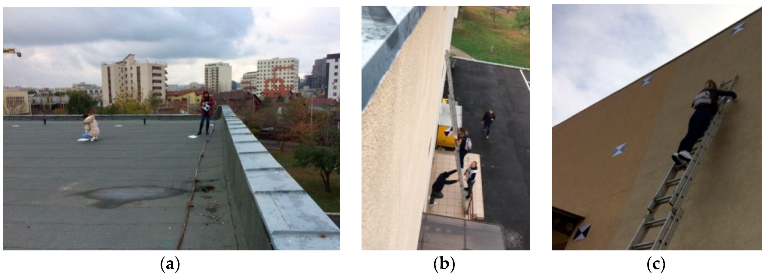
Figure 1.
Marking the ground control points (a) on the building roof, (b) and (c) on the facade.
Figure 1.
Marking the ground control points (a) on the building roof, (b) and (c) on the facade.
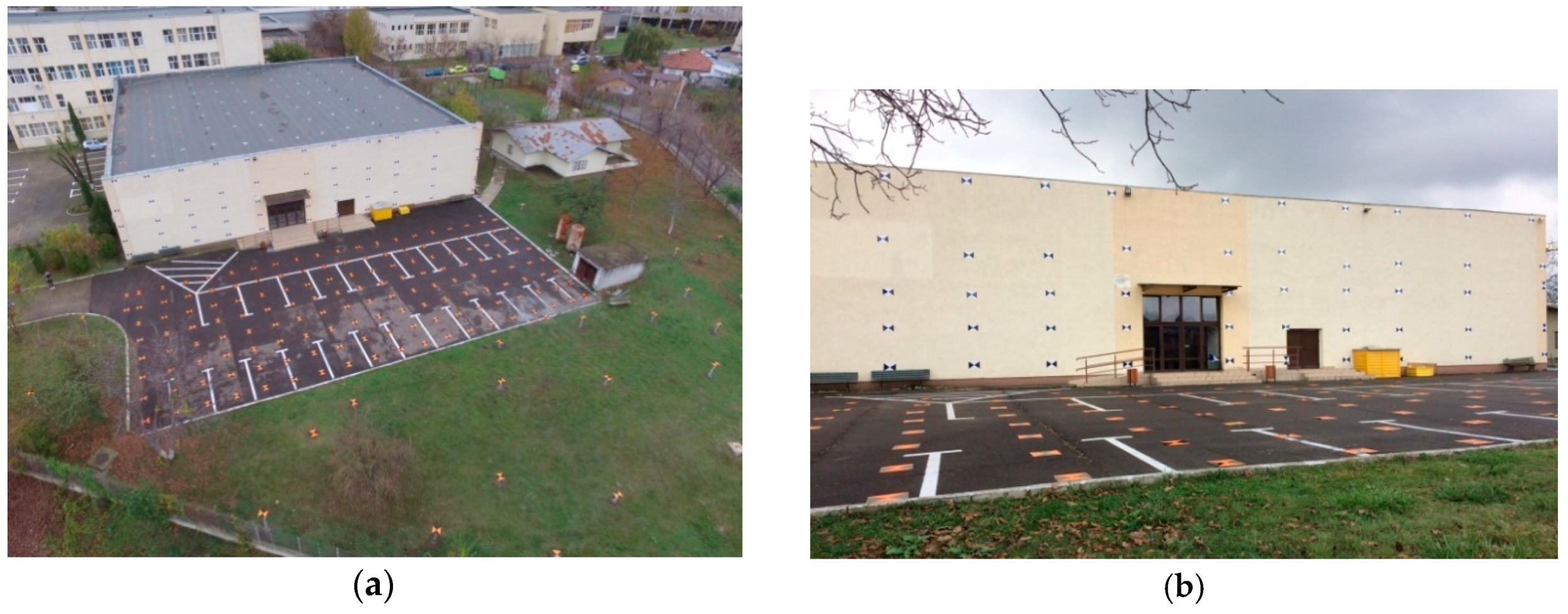
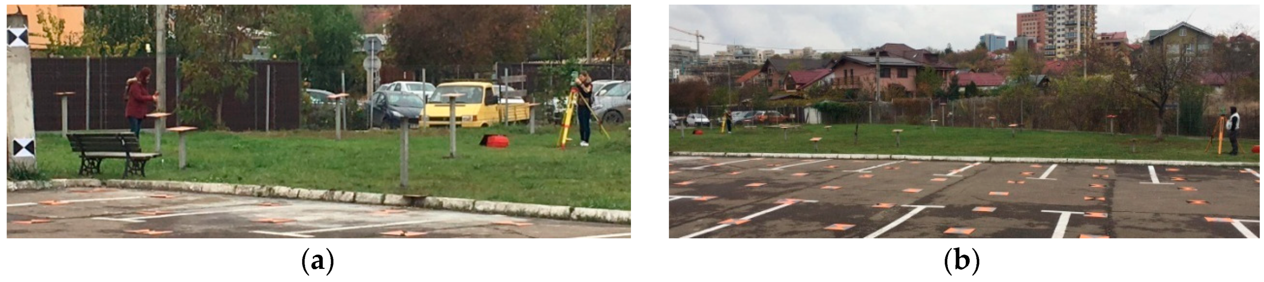
Figure 2.
(a) UAS image over the 3D calibration field of digital non-metric cameras mounted on Unmanned Aerial Systems, (b) ground image.
Figure 2.
(a) UAS image over the 3D calibration field of digital non-metric cameras mounted on Unmanned Aerial Systems, (b) ground image.
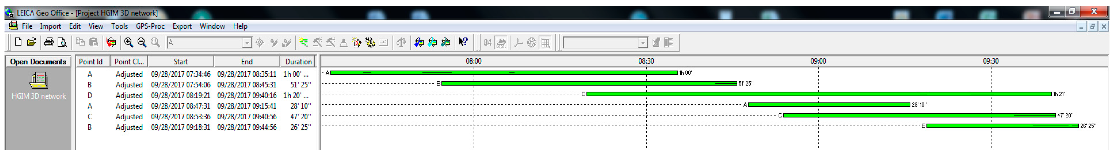
Figure 4.
GNSS observations sessions.
Figure 4.
GNSS observations sessions.
Figure 5.
(a) Taking the measurements using a miniprism and (b) two Leica TCR 405 total stations, centered on A and B GNSS points.
Figure 5.
(a) Taking the measurements using a miniprism and (b) two Leica TCR 405 total stations, centered on A and B GNSS points.
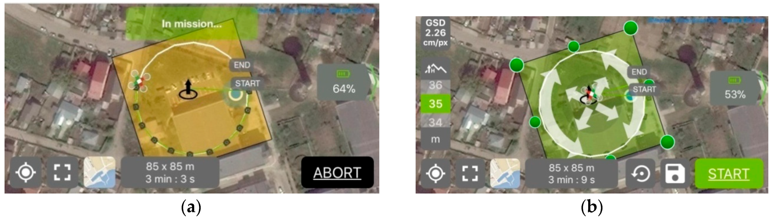
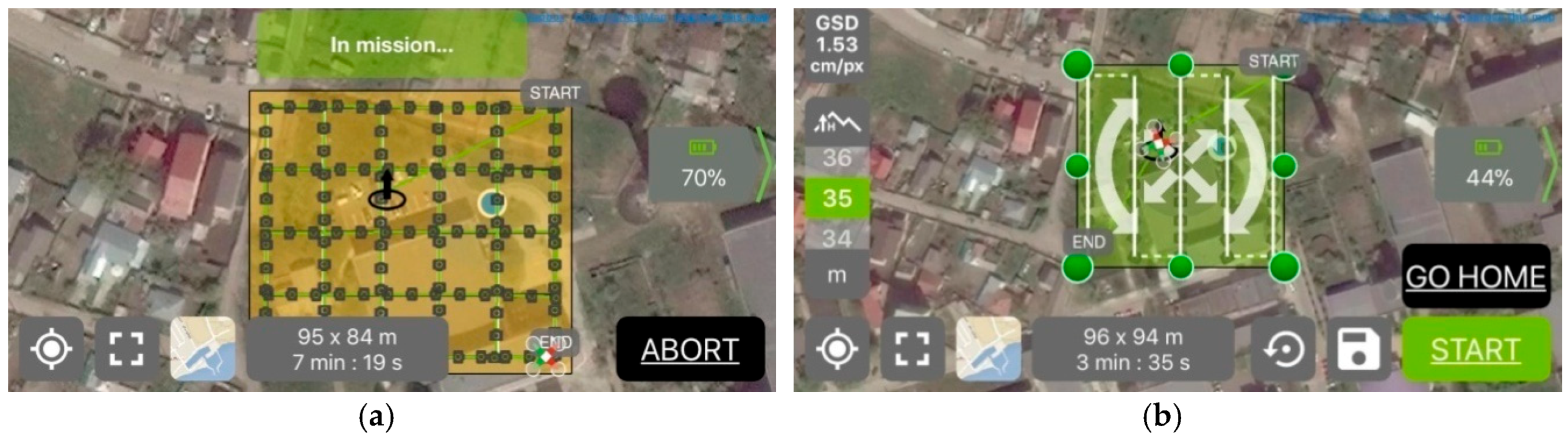
Figure 6.
Screen shots during the UAS image acquisition over the 3D calibration field for digital cameras mounted on UAS platforms at (a) 28 m height and (b) 35 m height.
Figure 6.
Screen shots during the UAS image acquisition over the 3D calibration field for digital cameras mounted on UAS platforms at (a) 28 m height and (b) 35 m height.
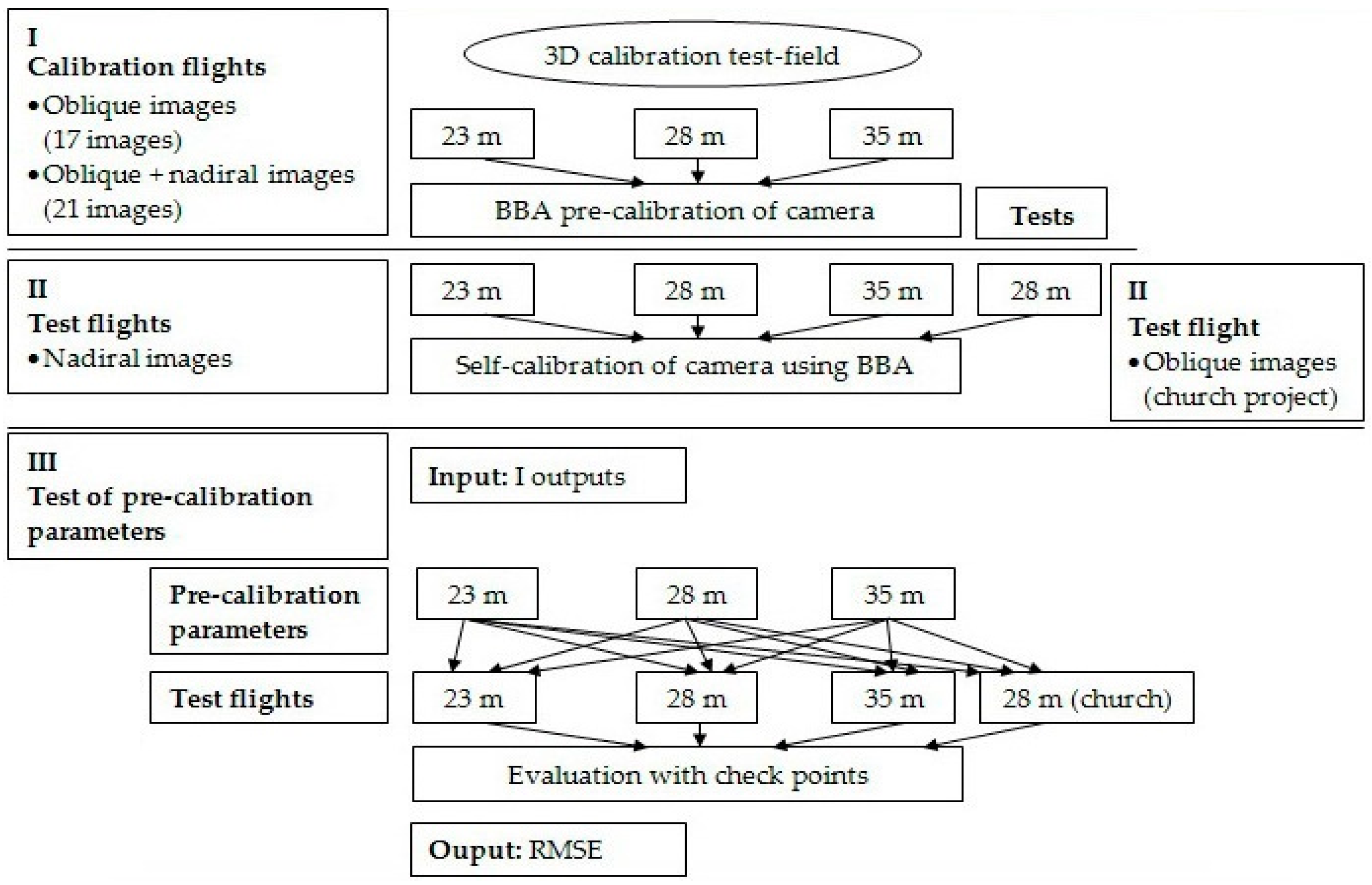
Figure 7.
Experiments workflow.
Figure 7.
Experiments workflow.
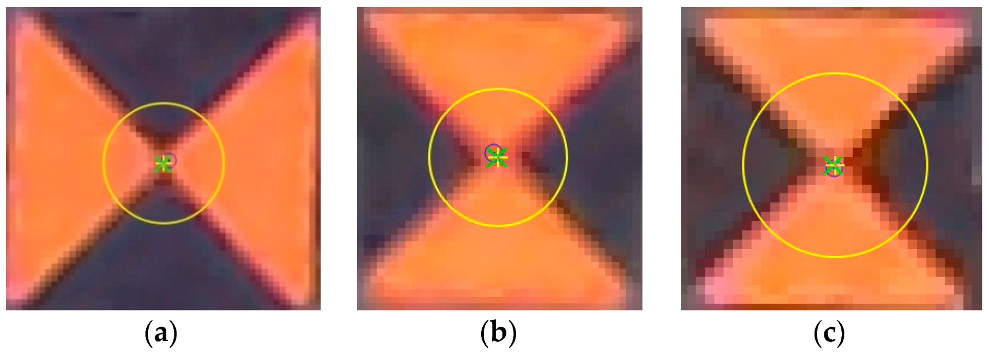
Figure 8.
Screen shots with a control point image in Pix 4D Mapper (No. 229) positioned approximatively in the calibration field center (a) 23 m height, (b) 28 m and (c) 35 m height.
Figure 8.
Screen shots with a control point image in Pix 4D Mapper (No. 229) positioned approximatively in the calibration field center (a) 23 m height, (b) 28 m and (c) 35 m height.
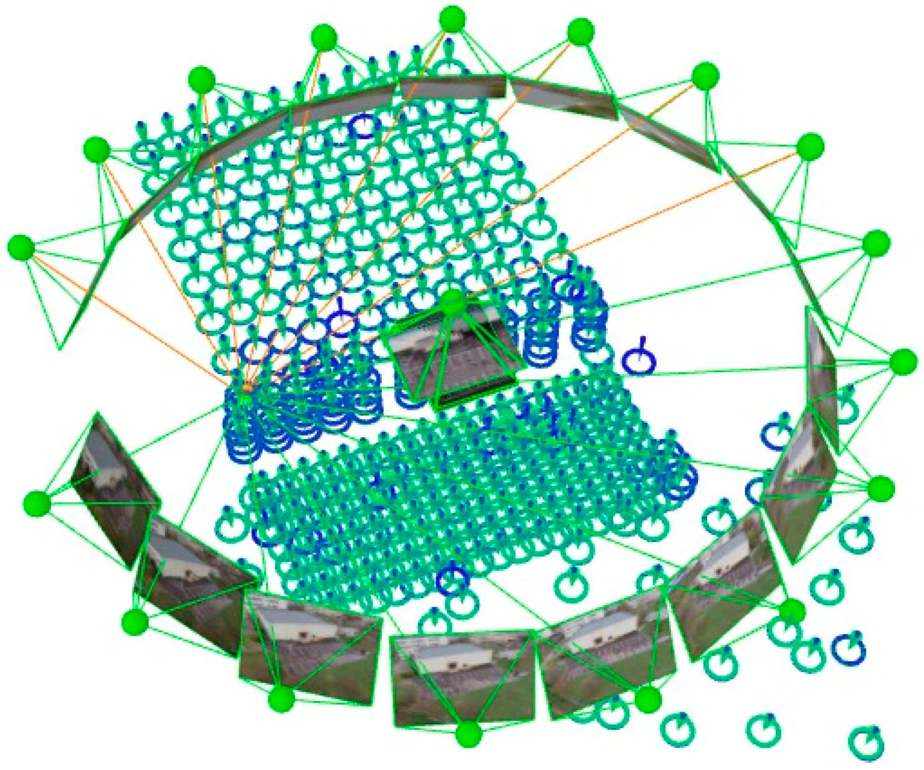
Figure 9.
The elements resulted after the bundle adjustment process: cameras positions and orientations, GCPs positions and errors marked with green arrow.
Figure 9.
The elements resulted after the bundle adjustment process: cameras positions and orientations, GCPs positions and errors marked with green arrow.
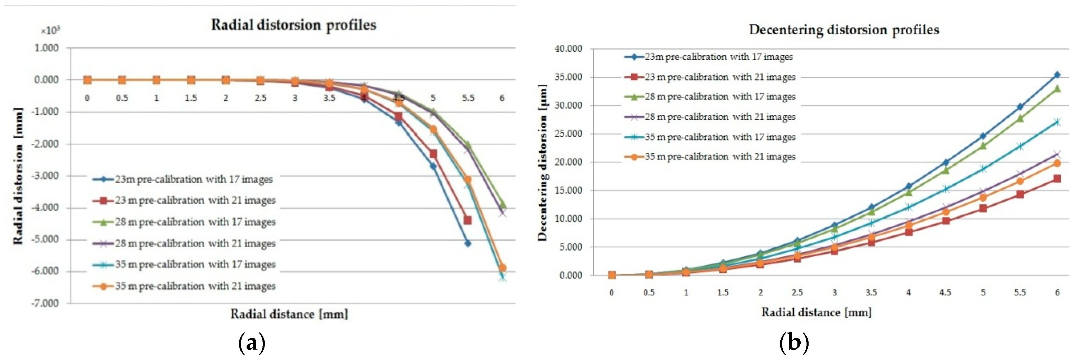
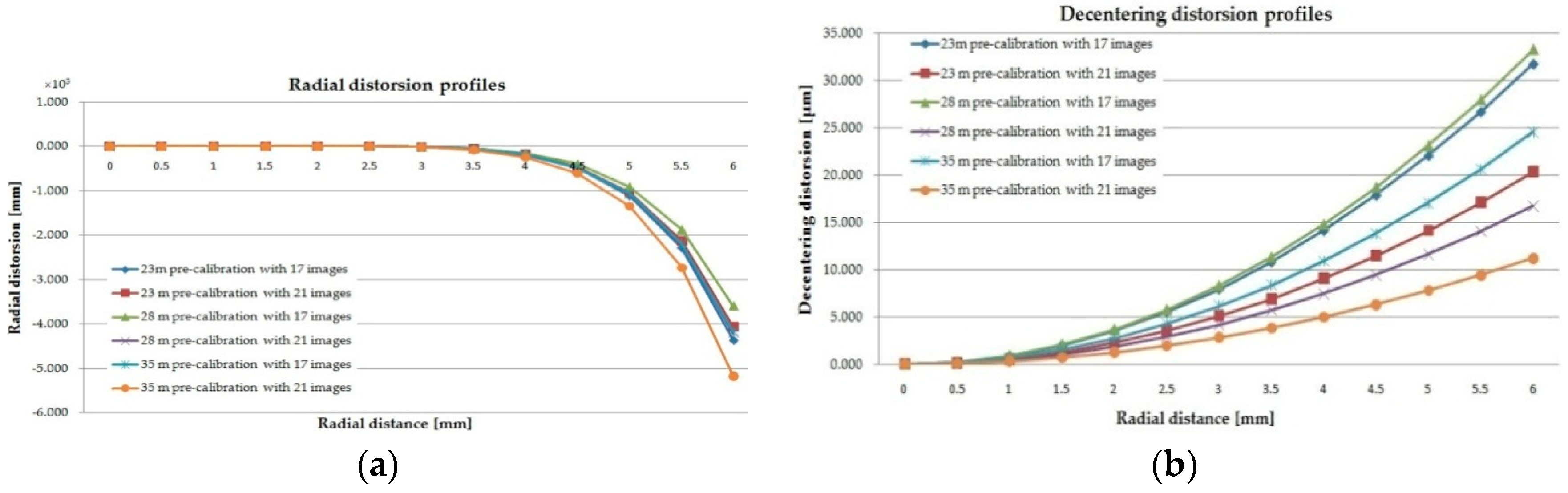
Figure 10.
(a) Radial and (b) decentering distortion profiles for the digital camera mounted on “DJI Phantom 3 standard” UAS at 23, 28, and 35 m height for 17 oblique images and 21 oblique and nadiral images.
Figure 10.
(a) Radial and (b) decentering distortion profiles for the digital camera mounted on “DJI Phantom 3 standard” UAS at 23, 28, and 35 m height for 17 oblique images and 21 oblique and nadiral images.
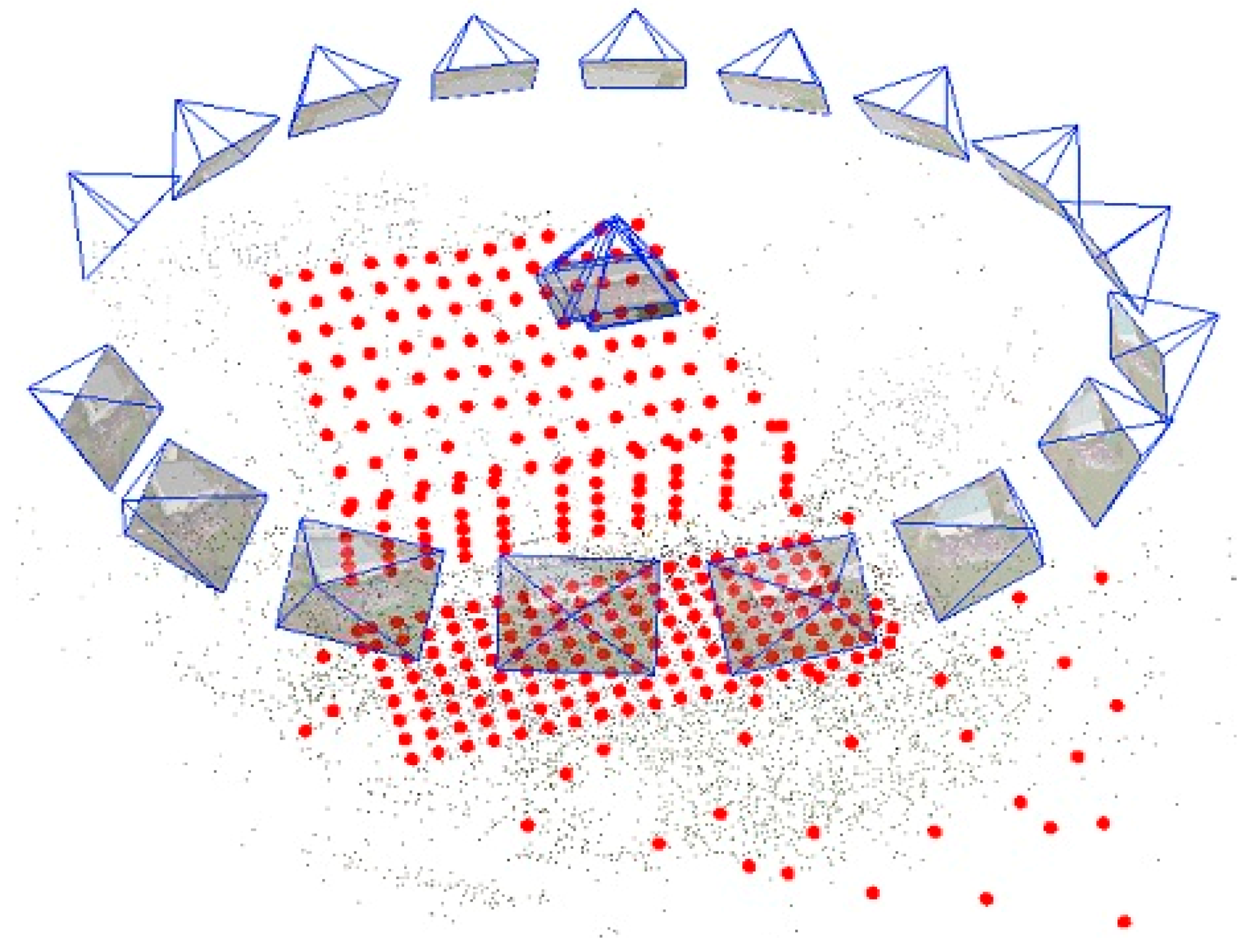
Figure 11.
The elements resulted after the bundle adjustment process: cameras positions and orientations, GCPs positions and sparse point cloud.
Figure 11.
The elements resulted after the bundle adjustment process: cameras positions and orientations, GCPs positions and sparse point cloud.
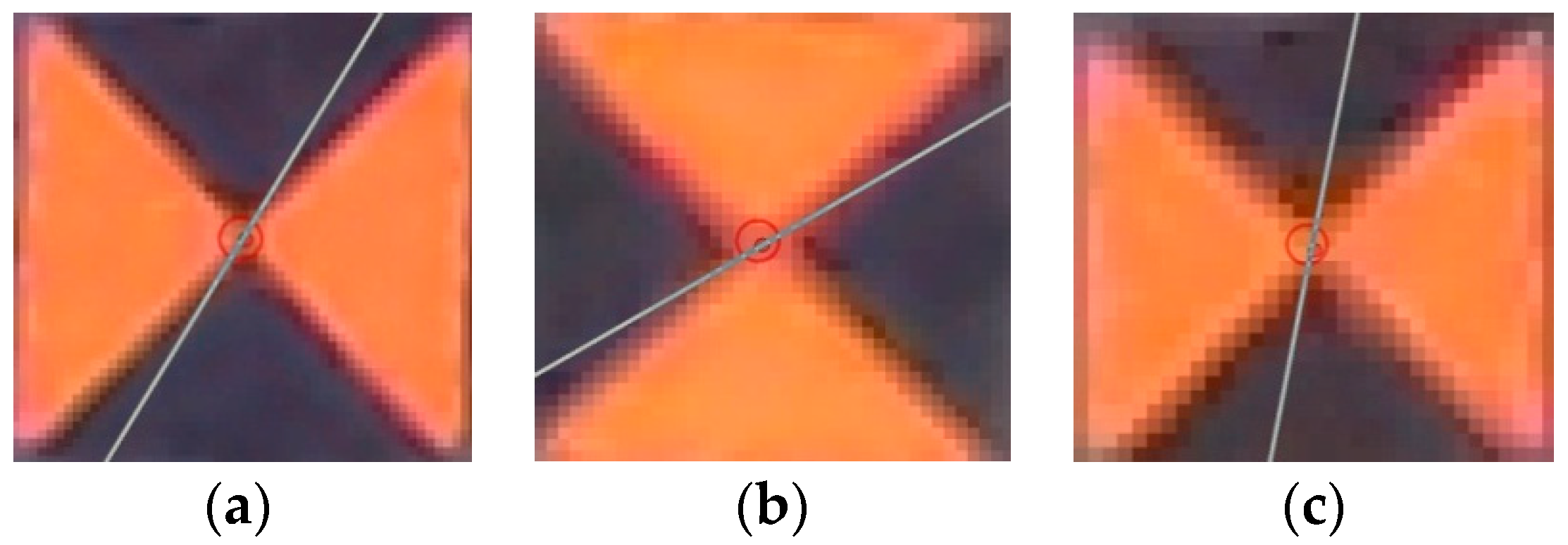
Figure 12.
Screen shots with a GCP image in “3DF Zephyr Pro” software (No. 229) positioned approximatively in the calibration field center (a) 23 m height, (b) 28 m and (c) 35 m height.
Figure 12.
Screen shots with a GCP image in “3DF Zephyr Pro” software (No. 229) positioned approximatively in the calibration field center (a) 23 m height, (b) 28 m and (c) 35 m height.
Figure 13.
(a) Radial and (b) decentering distortion profiles for the digital camera mounted on “DJI Phantom 3 Standard” UAS at 23, 28 and 35 m height for 17 oblique images and 21 oblique and nadiral images.
Figure 13.
(a) Radial and (b) decentering distortion profiles for the digital camera mounted on “DJI Phantom 3 Standard” UAS at 23, 28 and 35 m height for 17 oblique images and 21 oblique and nadiral images.
Figure 14.
Taking the UAS images over the calibration field at (a) 28 m and (b) 35 m.
Figure 14.
Taking the UAS images over the calibration field at (a) 28 m and (b) 35 m.
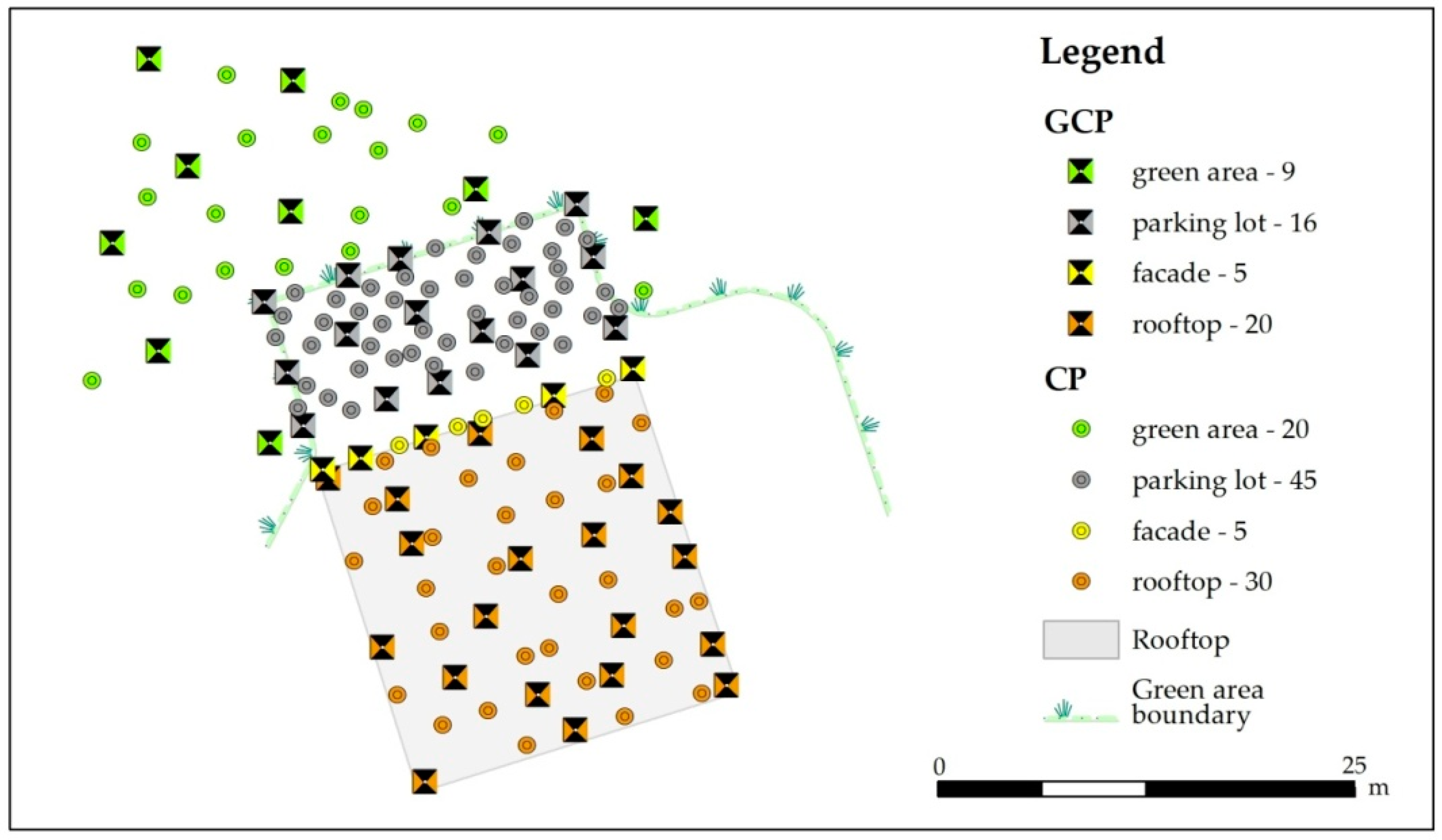
Figure 15.
The 50 GCPs and 100 CPs distribution.
Figure 15.
The 50 GCPs and 100 CPs distribution.
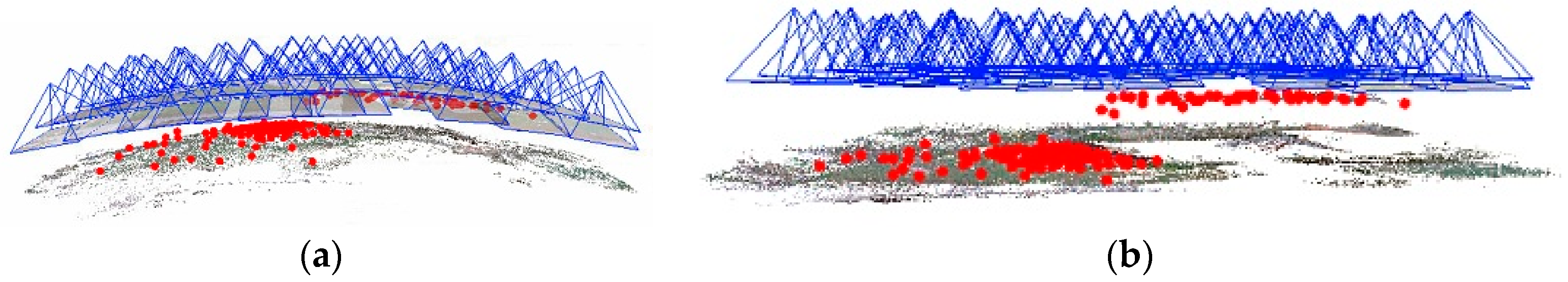
Figure 16.
Images and tie points positions for the 23 m nadiral flight after the orientation process using (a) SfM method and (b) pre-calibration parameters.
Figure 16.
Images and tie points positions for the 23 m nadiral flight after the orientation process using (a) SfM method and (b) pre-calibration parameters.
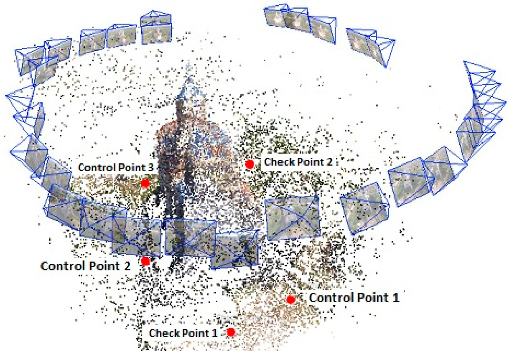
Figure 17.
The elements resulted after the bundle adjustment process: cameras positions and orientations and GCPs and CPs positions.
Figure 17.
The elements resulted after the bundle adjustment process: cameras positions and orientations and GCPs and CPs positions.
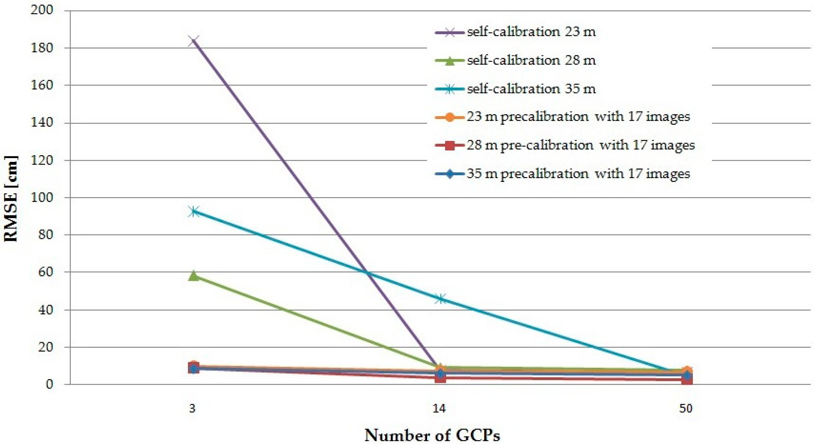
Figure 18.
The RMSE resulted for the 23 m, 28 m, and 35 m flights when using self-calibration and pre-calibration with oblique images.
Figure 18.
The RMSE resulted for the 23 m, 28 m, and 35 m flights when using self-calibration and pre-calibration with oblique images.
Table 1.
The non-closures calculation of GNSS network polygons.
Table 1.
The non-closures calculation of GNSS network polygons.
| No. | Polygons | Errors of Closers in Polygons (m) | Length of Polygon |
|---|
| e_EST | e_NORTH | e_H | et | Lt (m) |
|---|
| 1 | D–B–C | 0.0048 | 0.0023 | −0.0163 | 0.0172 | 88.2947 |
| 2 | C–B–A | −0.0060 | 0.0024 | 0.0304 | 0.0310 | 106.4422 |
| 3 | D–C–A | −0.0002 | 0.0010 | −0.0033 | 0.0034 | 113.0794 |
Table 2.
“Local-HGIM” stereographical projection parameters.
Table 2.
“Local-HGIM” stereographical projection parameters.
| Parameter | Value |
|---|
| Latitudine of natural origin (real) | φo = 47°09′21.96″ (north latitudine) |
| Longitudine of natural origin (real) | λo = 27°35′54.24″ (east longitudine) |
| Scale factor | Ko = 1 (tangential projection) |
| False north (translated coordinates of natural origin) | No = Xo = 1000.000 m |
| False east (translated coordinates of natural origin) | Eo = Yo = 1000.000 m |
Table 3.
Summary of full bundle adjustment (BBA) quality report.
Table 3.
Summary of full bundle adjustment (BBA) quality report.
| Height (m) | 23 | 28 | 35 |
|---|
| No. images | 21 | 17 | 21 | 17 | 21 | 17 |
| Mean GSD (cm) | 3.9 | 3.6 | 2.6 | 2.7 | 2.1 | 2.3 |
| Mean RMSE (mm) | 9 | 8 | 6 | 6 | 6 | 6 |
| Mean reprojection error (pixels) | 0.215 | 0.239 | 0.182 | 0.231 | 0.205 | 0.243 |
| Number of 2D keypoint observations for BBA | 42,078 | 77,507 | 47,166 | 81,841 | 88,266 | 110,229 |
| Mean number of matched 2D keypoint per image | 2004 | 4559 | 2246 | 4814 | 4203 | 6484 |
| Number of 3D points for BBA | 19,216 | 34,893 | 22,343 | 34,455 | 37,202 | 41,473 |
Table 4.
Interior orientation parameters calculated for the “GoPro” digital camera at 3 different heights: 23 m, 28 m and 35 m using “Pix 4D Mapper”software.
Table 4.
Interior orientation parameters calculated for the “GoPro” digital camera at 3 different heights: 23 m, 28 m and 35 m using “Pix 4D Mapper”software.
| Height (m) | No. of Images | f (mm)/pixels | u0 (mm)/(pixels) | v0 (mm)/(pixels) | k1 | k2 | k3 | p1 × 10−4 | p2 × 10−4 |
|---|
| 23 | 21 | 4.27808 | 3.11761 | 2.32975 | −0.129361 | 0.110143 | −0.018652 | −2.3613 | 4.11071 |
| 2708.73 | 1973.96 | 1475.11 |
| 17 | 4.27885 | 3.12531 | 2.32776 | −0.130439 | 0.113851 | −0.021348 | −2.01641 | 9.64783 |
| 2709.21 | 1978.83 | 1473.85 |
| 28 | 21 | 4.27674 | 1974.82 | 1476.65 | −0.129152 | 0.108773 | −0.017812 | −1.91946 | 5.62797 |
| 2707.87 |
| 17 | 4.27991 | 3.12421 | 2.32587 | −0.128664 | 0.108156 | −0.016712 | −1.9623 | 8.96893 |
| 2709.89 | 1978.14 | 1472.65 |
| 35 | 21 | 4.27975 | 3.11853 | 2.33246 | −0.131715 | 0.116669 | −0.024146 | −2.19276 | 5.06711 |
| 2709.78 | 1974.54 | 1476.83 |
| 17 | 4.28529 | 3.1219 | 2.32524 | −0.131707 | 0.117748 | −0.025275 | −1.31255 | 7.42829 |
| 2713.29 | 1976.67 | 1472.26 |
Table 5.
Summary of full bundle block adjustment (BBA) quality report.
Table 5.
Summary of full bundle block adjustment (BBA) quality report.
| Height (m) | 23 | 28 | 35 |
|---|
| No. of images | 21 | 17 | 21 | 17 | 21 | 17 |
| Mean GSD (cm) | 1.6 | 1.8 | 1.9 | 2.0 | 1.7 | 1.9 |
| Mean RMSE (mm) | 11 | 11 | 9 | 9 | 10 | 10 |
| Mean reprojection error (pixels) | 0.572 | 0.542 | 0.501 | 0.276 | 0.604 | 0.290 |
| 3D points per image | 596 | 582 | 1537 | 632 | 1510 | 1017 |
| Number of 3D points for BBA | 5265 | 4330 | 11,877 | 10,758 | 11,659 | 7330 |
Table 6.
Interior orientation parameters calculated for the “GoPro” digital camera at 3 different heights: 23 m, 28 m, and 35 m using “3DF Zephyr Pro” software.
Table 6.
Interior orientation parameters calculated for the “GoPro” digital camera at 3 different heights: 23 m, 28 m, and 35 m using “3DF Zephyr Pro” software.
| Height (m) | No. of Images | f (mm)/pixels | u0 (mm)/(pixeli) | v0 (mm)/(pixeli) | k1 | k2 | k3 | p1 × 10−4 | p2 × 10−4 |
|---|
| 23 | 21 | 2707.326 | 1974.823 | 1477.729 | −0.12940 | 0.109243 | −0.017431 | −2.1990 | 5.2146 |
| 17 | 2710.399 | 1978.085 | 1472.805 | −0.13008 | 0.118661 | −0.018778 | −1.1667 | 8.7533 |
| 28 | 21 | 2707.599 | 1973.953 | 1477.729 | −0.12983 | 0.109752 | −0.017975 | −1.5643 | 4.3785 |
| 17 | 2709.921 | 1978.267 | 1472.582 | −0.12837 | 0.107149 | −0.015723 | −1.8728 | 9.0569 |
| 35 | 21 | 2709.367 | 1972.562 | 1476.918 | −0.13098 | 0.113706 | −0.021533 | −1.9484 | 2.4395 |
| 17 | 2710.847 | 1975.954 | 1474.430 | −0.12919 | 0.109489 | −0.017830 | −1.7114 | 6.6117 |
Table 7.
The residuals of 100 CPs for a 28 m nadiral flight when using self-calibration and pre-calibration at 28 m height done with “Pix 4D Mapper” respectively “3DF Zephyr”.
Table 7.
The residuals of 100 CPs for a 28 m nadiral flight when using self-calibration and pre-calibration at 28 m height done with “Pix 4D Mapper” respectively “3DF Zephyr”.
| Height for Pre-Calibration (m) | No. of GCPs | Self-Calibration 28 m Height RMSE (cm) | Pre-Calibration with 17 Images RMSE (cm) |
|---|
| Pix4D Mapper | 3DF Zephyr Pro |
|---|
| 28 | 3 | 58.4 | 13.7 | 9.0 |
| 14 | 9.1 | 4.31 | 4.11 |
| 50 | 7.6 | 3.29 | 2.95 |
Table 8.
The residuals of 87 CPs for a 23 m nadiral flight when using self-calibration and pre-calibration at 3 different heights: 23 m, 28 m and 35 m with two image configuration in the case of a different number of GCPs.
Table 8.
The residuals of 87 CPs for a 23 m nadiral flight when using self-calibration and pre-calibration at 3 different heights: 23 m, 28 m and 35 m with two image configuration in the case of a different number of GCPs.
| Height for Pre-Calibration (m) | No. of GCPs | Self-Calibration 23 m Height RMSE (cm) and RMSE/GSD | Pre-Calibration RMSE (cm) and RMSE/GSD |
|---|
| 21 Images | 17 Images |
|---|
| 23 | 3 | 184/197.8 | 10.1/10.9 | 10/10.8 |
| 14 | 7.8/8.4 | 7.7/8.3 | 7.7/8.3 |
| 50 | 6.5/7.0 | 7.0/7.5 | 7.0/7.5 |
| 28 | 3 | 184/197.8 | 10.7/11.5 | 10.4/11.2 |
| 14 | 7.8/8.4 | 7.7/8.3 | 7.9/8.5 |
| 50 | 6.5/7.0 | 7.0/7.5 | 7.2/7.7 |
| 35 | 3 | 184/197.8 | 10.9/11.7 | 10/10.8 |
| 14 | 7.8/8.4 | 7.9/8.5 | 7.8/8.4 |
| 50 | 6.5/7.0 | 6.9/7.4 | 7.0/7.5 |
Table 9.
The residuals of 100 CPs for a 28 m nadiral flight when using self-calibration and pre-calibration at 3 different heights: 23 m, 28 m and 35 m with two image configuration in the case of a different number of GCPs.
Table 9.
The residuals of 100 CPs for a 28 m nadiral flight when using self-calibration and pre-calibration at 3 different heights: 23 m, 28 m and 35 m with two image configuration in the case of a different number of GCPs.
| Height for Pre-Calibration (m) | No. of GCPs | Self-Calibration 28 m Height RMSE (cm) and RMSE/GSD | Pre-Calibration RMSE (cm) and RMSE/GSD |
|---|
| 21 Images | 17 Images |
|---|
| 23 | 3 | 58.4/53.1 | 14.7/13.4 | 12.3/11.2 |
| 14 | 9.1/8.3 | 4.2/3.8 | 4.0/3.6 |
| 50 | 7.6/6.9 | 3.3/3.0 | 3.2/2.9 |
| 28 | 3 | 58.4/53.1 | 14.4/13.1 | 9.0/8.2 |
| 14 | 9.1/8.3 | 3.9/3.5 | 4.1/3.7 |
| 50 | 7.6/6.9 | 3.2/2.9 | 2.95/2.7 |
| 35 | 3 | 58.4/53.1 | 12.3/11.2 | 7.93/7.2 |
| 14 | 9.1/8.3 | 3.9/3.5 | 4.11/3.7 |
| 50 | 7.6/6.9 | 3.3/3.0 | 2.96/2.7 |
Table 10.
The residuals of 99 CPs for a 35 m nadiral flight when using self-calibration and pre-calibration at 3 different heights: 23 m, 28 m and 35 m in the case of a different number of GCPs.
Table 10.
The residuals of 99 CPs for a 35 m nadiral flight when using self-calibration and pre-calibration at 3 different heights: 23 m, 28 m and 35 m in the case of a different number of GCPs.
| Height for Pre-Calibration (m) | No. of GCPs | Self-Calibration 35 m Height RMSE (cm) and RMSE/GSD | Pre-Calibration RMSE (cm) and RMSE/GSD |
|---|
| 21 Images | 17 Images |
|---|
| 23 | 3 | 92.6/65.2 | 9.0/6.3 | 10.2/7.2 |
| 14 | 45.9/32.3 | 6.5/4.6 | 6.2/4.4 |
| 50 | 4.8/3.4 | 5.1/3.6 | 5.0/3.5 |
| 28 | 3 | 92.6/65.2 | 9.6/6.8 | 9.8/6.9 |
| 14 | 45.9/32.3 | 6.4/4.5 | 6.1/4.3 |
| 50 | 4.8/3.4 | 5.1/3.6 | 4.9/3.5 |
| 35 | 3 | 92.6/65.2 | 10/7.0 | 8.8/6.2 |
| 14 | 45.9/32.3 | 6.3/4.4 | 6.2/4.4 |
| 50 | 4.8/3.4 | 5.1/3.6 | 5.2/3.7 |
Table 11.
The residuals of 2 CPs resulted after BBA process for an oblique flight when using self-calibration and pre-calibration at 3 different heights: 23 m, 28 m and 35 m.
Table 11.
The residuals of 2 CPs resulted after BBA process for an oblique flight when using self-calibration and pre-calibration at 3 different heights: 23 m, 28 m and 35 m.
| Height for Pre-Calibration (m) | Self-Calibration RMSE (cm) and RMSE/GSD | Pre-Calibration RMSE (cm) and RMSE/GSD |
|---|
| 21 Images | 17 Images |
|---|
| 23 | 5.2/4.7 | 2.0/1.8 | 1.9/1.7 |
| 28 | 5.2/4.7 | 2.0/1.8 | 1.8/1.6 |
| 35 | 5.2/4.7 | 2.1/1.9 | 1.9/1.7 |
Table 12.
The residuals of 2 CPs for an oblique flight when using self-calibration and pre-calibration at 23 m, 28 m and 35 m height.
Table 12.
The residuals of 2 CPs for an oblique flight when using self-calibration and pre-calibration at 23 m, 28 m and 35 m height.
| Height for Pre-Calibration (m) | | 21 Images RMSE (cm) | 17 Images RMSE (cm) |
|---|
| Check Point 1 | Check Point 2 | Check Point 1 | Check Point 2 |
|---|
| Self-calibration | 10.3 | 13.7 | 10.3 | 13.7 |
| 23 | 4.0 | 4.2 | 4.0 | 3.9 |
| 28 | 4.0 | 4.4 | 3.6 | 3.7 |
| 35 | 4.2 | 4.5 | 4.1 | 4.3 |


