1. Introduction
Wind power plants are increasingly important sources of clean energy that have a minimal environmental impact. Many wind energy technologies have been explored, and numerous wind farms have been installed on existing energy networks. Due to unpredictable nature of wind energy and its dependency on environmental conditions, it is usually required to integrate various renewable energy sources to form a hybrid system to provide high-quality and sustainable energy. Several aspects should be considered to provide suitable strategies for the stability and control of hybrid power systems [
1].
Determining the optimal operating point of the wind turbine that produces maximum energy is essential. Therefore, many attempts have been done throughout the years to develop a suitable controller for maximum power point tracking (MPPT) for wind energy systems. In [
2], dynamic operation and control strategies for a microgrid hybrid wind/photovoltaic/fuel cell have been examined and the proposed algorithm successfully controlled voltage and power under different weather conditions. Another intelligent controller for MPPT has been proposed for a hybrid solar/wind/diesel-engine power system [
3].
From the power system stability point of view, the wind turbine should be able to remain connected to the network during faults. This capability of wind turbines, which should be taken in account in designing wind turbine controller and protection system, is called the fault ride-through (FRT) capability. On the other hand, fault current limiter (FCL) or fault current controller should be applied in the wind power plants to protect the entire system. A fault analysis method for unbalanced distribution networks is proposed in [
4], and a novel unsymmetrical faults analysis technique with hybrid compensation for microgrid distribution systems is presented in [
5]. An algorithm for ground fault analysis of microgrid distribution was also proposed in [
6]. In order to improve the transient stability, reduce the power fluctuations, and voltage support in a hybrid offshore wind farm/seashore wave power farm system, an intelligent damping controller has been proposed for a static synchronous compensator [
7].
The overall performance of wind power depends on the subsystems of power plants, including those for reactive power compensation and energy storage, as these latter two components maintain the energy stability given varying electrical loads [
8]. Even though the latest technologies enable wind generators to directly inject or absorb reactive power from the distribution network, most currently installed wind turbines use an inductor generator without voltage regulation or the ability to absorb grid reactive power [
9]. In the past several years, the squirrel cage rotor induction generator has been commonly offered by wind turbine manufacturers as a trusted and inexpensive alternative. Squirrel cage rotor induction generators serve as induction machines and have capacitor modules that function as reactive power compensators to correct for differences in power factors; however, local reactive power compensation is unable to minimize the power losses and maximize bus voltages at levels that are satisfactory for many current wind farm owners [
10].
Two different strategies have been proposed in the literature to fix the problem of poor reactive power compensation in wind farms. A single compensation center may be installed, based on a centralized approach, whereas a distributed approach may rely on compensation at each bus of a wind farm [
11,
12,
13]. Optimal capacitor placement in existing wind farms represents a distributed approach for partially compensating for reactive power in order to minimize energy losses and to optimize the cost of reactive power management [
9]. This method is simple and relatively inexpensive, and can be implemented after wind farms have already been established.
Clear benefits result from using capacitors to fix operational problems in different aspects of energy distribution systems; however, because of the complexity in finding the best location and size of these devices in networks, many research studies have focused on optimal capacitor placement. One comparative study on the optimal placement of shunt capacitors in energy distribution systems detailed several of the previously used methods for solving this problem, including analytical methods, numerical programming methods, heuristics methods, artificial intelligent methods, and multi-dimensional problems [
14]. Another comprehensive review of heuristic optimization techniques proposed from 2001 to 2011 for optimal capacitor placement was presented in [
15].
Further studies on optimal capacitor placement have been carried out in recent years, and new hybrid approaches, as well as new constraints, have been considered in the literature. In [
16], a sensitivity index was first formulated to identify the most critical and suitable nodes for capacitor placement based on improvements in the voltage profile and the reductions in power loss. In the second stage, a combined fuzzy and GA-based approach was applied to determine the optimal size of capacitors, to improve the power factor, to reduce the burden on the substation, to decrease power loss, and to minimize voltage deviation in the distribution network. In [
17], to overcome slow convergence, a hybrid optimization method based on the Harmony Search Algorithm (HSA) and the Particle Artificial Bee Colony algorithm (PABC) was proposed for optimal capacitor placement. The objectives were to minimize power loss and to improve the voltage profile in radial distribution networks. In [
18], to reduce power loss and to improve bus voltages in unbalanced power systems, an optimal reconfiguration of distribution systems and placement of capacitors were simultaneously solved through combining the Big Bang–Big Crunch algorithm and a fuzzy-based multi-objective programming method. In [
19], the suitable nodes for capacitor installation were determined by calculating the voltage stability and loss sensitivity indexes. Then, the optimum size of capacitors at candidate nodes was calculated by the Bacterial Foraging Optimization Algorithm (BFOA), considering the load variations from light to peak loads. In [
20], to minimize power loss and voltage deviation, Particle Swarm Optimization (PSO) was applied to solve the capacitor allocation problem for a modified distribution network connected to wind energy. Because of the uncertainties in wind speed and poor reactive power compensation, the fitness cost function in the study was nonlinear, and appropriate mathematical tools were applied. The Whale Optimization Algorithm (WOA) [
21] and the Shark Smell Optimization (SSO) algorithm [
22] are two additional recently developed metaheuristic optimization techniques that have been used to solve the optimal capacitor problem in distribution networks.
Several additional approaches have also contemplated harmonics. In particular, the most important power quality problems in wind power plants stem from the variance in harmonics across a system; these problems must be seriously considered during energy management. For example, the power conductors in wind power plants have high switching frequencies. Also, many elements in wind farms, such as power cables, transformers, reactors, and capacitor banks have nonlinear behavior and can resonate with one another. Even so, the installation of additional shun capacitors for partial reactive compensation will increase the nonlinearity of the system components and therefore make harmonic considerations inevitable. In [
23], power quality constraints such as total harmonic distortion (THD) and maximum voltage deviation were taken into account to determine the optimum placement, size, and number of both switched and fixed capacitors. The multi-objective formulation was solved by the Non-Dominated Sorting Genetic Algorithm (NSGA-II), and tested on a practical example. In [
24], transient switching overvoltages were examined as a novel approach in the process of deciding optimal capacitor placement in order to minimize losses and THD on a long-term horizon.
In the present work, we aimed to determine the best location and size of capacitors in an existing wind farm in order to support local reactive power compensation and to thereby minimize energy losses and total costs. We evaluated system equivalent circuits in two cases, either considering or disregarding harmonics, and also based our determinations on modelled wind speed and wind power generation. The most important components of hybrid power systems that are used for the efficient and flexible interconnection of renewable energy resources are electronic convertors. In addition, several stable power sources, such as batteries, fuel cells, super-capacitors, or diesel generators, must be integrated into hybrid systems to supply sufficient and stable power [
1]. These additional devices make a lot of technical challenges on the power quality of systems and capacitors may not be able to provide reactive power requirement. For this reason, the present paper only focuses on the existing wind farms and neglects the hybrid power systems.
In [
9], optimal capacitor placement in an existing wind farms, has been proposed as a partial reactive power compensation approach. A genetic algorithm was applied to find a limited number of capacitors on different buses and the effect of harmonics was neglected. In the present paper, by considering the harmonic distortion in the system components, the equivalent circuit is modified. For the first time, total harmonic distortion after capacitor placement is controlled in the wind farms and harmonic power loss has been considered in energy loss calculations.
In particular, for the purposes of the present study, a discrete version of the lightning search algorithm (DLSA) is proposed and developed at following. Proposed in 2015, the lightening search algorithm (LSA) is a powerful and flexible optimization technique [
25] that was inspired by the natural phenomenon of lightning. Some engineering optimization problems related to the parameter extraction of solar cell models [
26], as well as modelling wind power [
27], controlling voltage and frequency in a solar thermal power plant [
28], and designing a speed controller for an induction motor drive [
29], have been recently and successfully solved by applying the LSA method. The results obtained by the DLSA for the optimal placement of capacitors were compared with the results obtained by the genetic algorithm (GA), and the discrete harmony search algorithm (DHSA) at different wind speeds considering or disregarding harmonics. The results demonstrate the effectiveness of the DLSA method; this method showed a faster convergence and better convergence characteristics in comparison to other methods. DLSA is proposed for the first time to show the application of a novel discrete optimization technique in solving complex problems in large scale.
2. System Equivalent Circuit
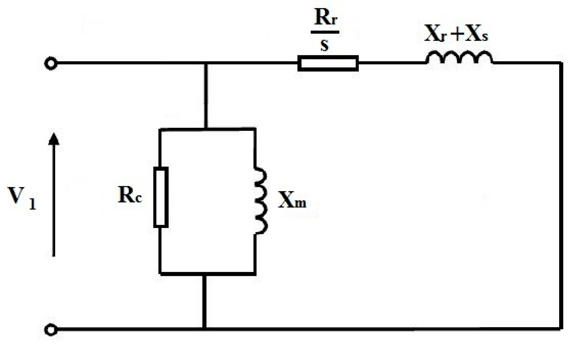
As induction generators are widely used in wind farms, these must be first modelled in order to analyse the wind farm system. In practice, the stator resistance is negligible, and the induction generator per-phase equivalent circuit can be simplified, as shown in
Figure 1, where
s is the induction generator slip and
V1 is the generator input voltage.
Rc and
Xm are open circuit resistance and reactance, respectively.
Rr and
Xr are rotor resistance and reactance, respectively.
Xs is stator reactance.
Considering the simplified equivalent circuit, we can compute the produced active power and the absorbed reactive power at bus
j, as follows [
9]:
The power injected at bus
j is
where
is the reactive power compensated by bus
j, including automatic compensation in the wind turbine and the additional shunt capacitor. In practice, for a range of wind speeds from 4 to 25 m/s, the active wind power generated at bus
j can be approximated by
where
is the wind speed at node
j,
is the rated value of the wind turbine at bus
j, and the coefficients
c1 and
c2 are constants defined to minimise the approximation error [
9].
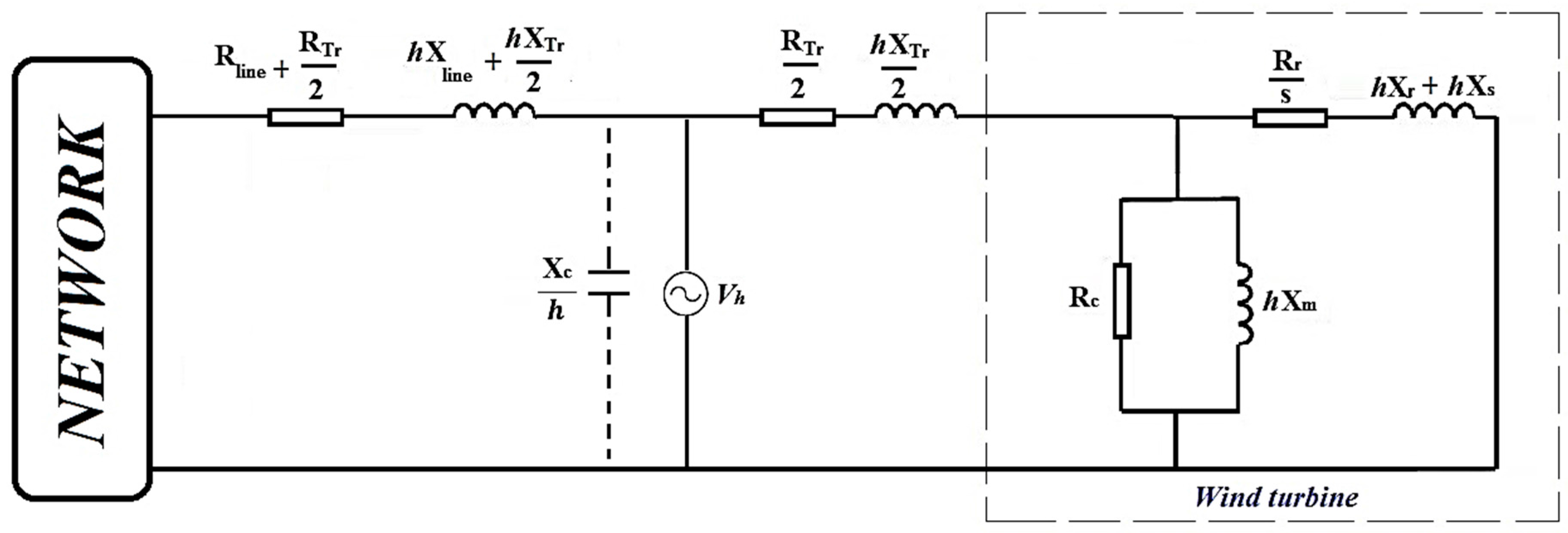
By considering the harmonic distortion in the system, the per-phase equivalent circuit of any wind turbine connected to the electric distribution system in wind farms can be modelled as in
Figure 2. In this circuit line feeder, the transformer, induction generator, and capacitor are modelled, and are connected to the network at each busbar. In this circuit,
h is the harmonic order, which is defined as the ratio of frequency under analysis and the fundamental frequency [
30].
The slip of the induction generator is a function of the harmonic frequency and is computed as follows [
30]:
where
sh is the wind turbine slip at the harmonic order of
h,
ωs is the synchronous speed and
ωr is the generator rotor speed.
The system admittance is proportional to the harmonic current flowing in the system. A change to capacitor size will be reflected in the system admittance for different harmonic frequencies; this variance represents the central problem addressed in this study. Consequently, the harmonic currents, harmonic voltages, and the amount of harmonic distortion at each bus will be also be completely modified.
3. Problem Formulation
The aim of the present exploration is to determine the optimal placement and size of capacitors for instalment on different buses of an existing wind farm in order to minimise energy losses, total cost, and reactive power absorption in the external distribution system considering voltage limits and maximum permissible harmonic distortion. To define the objective function, apart from the additional capacitor banks, we suppose a basic capacitor module that includes connection, switch and control subsystems.
For this study, the following objective function
F is considered.
where
N represents the number of lines;
M is the number of buses;
ΔEloss,k is energy loss per year at line
k in
$/(kWh/year);
is total reactive power at bus
j in (kVar); and,
CostQ(tatal) is yearly cost of purchased reactive power by the grid operator in the case of insufficient reactive power compensation at the wind farm
($/year);
Χa and
Χb are yearly depreciation of the installation and the maintenance costs, respectively, of basic modules and additional capacitor banks; and
Χe is average price of the unsold energy.
Kj is defined as a binary variable and is equal to 1 if a capacitor is present at bus
j and to 0 if no capacitor is present.
The energy losses at each line are computed by
where
Ploss,k is power loss at the
kth line in kW and
T is the duration. Total real power loss is defined by
in which
Ploss(Fund.) and Ploss(harmonics) are the fundamental and harmonic components of total power loss, respectively. Vj is the voltage at bus j. Ptot,j and Qtot,j are the total active and reactive powers at bus j, respectively, and Rj is the resistance of branch j. is magnitude of the jth branch current for the hth harmonic order. hmin and hmax are the minimum and maximum harmonic orders, respectively.
The objective function is minimised by being subjected to constraints defined by the limits of voltage and harmonic distortion at each bus, which are given as follows:
where
Vj is the voltage and
THDj (%) is the total harmonic distortion at
jth bus.
The optimal capacitor placement problem is formulated as a nonlinear integer optimization problem by considering both the capacitor location and size as discrete variables. Radial power flow and harmonic power flow programs should be run more than five hundred times and it is a sophisticated and time-consuming procedure. Therefore, a robust and reliable optimization technique that can solve complex discrete problems in large scale must be developed to solve such a problem. The lightening search algorithm (LSA) is a powerful and flexible optimization technique without many initial parameters that has been applied for many engineering problems. It is a fast, reliable, and simple method and can be updated to binary or discrete versions [
31].
4. Lightning Search Algorithm
The lightning search algorithm (LSA), proposed by Shareef et al. in 2015 [
25], is based on the natural phenomenon of lightning. Similar to the other metaheuristics algorithms, the LSA needs a population to begin the search. The fast particles in the search are known as projectiles. The process is divided into three types of projectiles: transition, space, and lead projectiles.
Transition Projectile: An early stage formation of step leaders results from the ejection of the transition projectile in a random direction. This can be modelled as a random number using uniform probability distribution.
where
represents the initial tip energy of the step leader. For a population of
N step leaders (SL), wherein
SL = [
sl1,
sl2,
sl3, …,
slN],
N random projectiles
PT = [
pT1,
pT2,
pT3, …,
pTN] that satisfy the solution dimensions are required.
Space Projectile: The space projectile enables the best leaders position to be reached by ionising the region of the previous leaders tip energy as step + 1, wherein step leaders are changed after N.
The space projectile
PS position = [
pS1,
pS2,
pS3, …,
pSN] at step + 1 can be partially modelled as a random number generated from an exponential distribution using the shaping parameter
μ, as follows:
The
at step + 1 can be represented at following:
Only in situations where the projectile energy ESp-i is greater than the step leader Esl-i can the path be extended and a good solution found; this guarantees new propagation or channel formation. If offers a good solution in the next step, then the sli leader moves to another position, and is updated to new . Otherwise, remains unchanged until the next step. If becomes the lead projectile if it extends sli-NEW beyond the most recent extended leader during the process.
Lead Projectile: The lead step travels closest to the ground, as its projectile does not have enough potential for ionising large sections in front of the leader tip. This lead projectile can be expressed as a random number obtained from a normal distribution, as follows:
The equation is defined by the shape parameter
and is capable of investigating all of the directions from the current position of the lead projectile, which has a holding capacity represented by a scale parameter (
). In the algorithm
μL for the lead projectile,
pL is taken as
pL, and the scale parameter
σL exponentially decreases as it moves closer to the ground or as it finds a better solution.
pL in step + 1 can be expressed as follows:
where
normrand represents the random number generated by the normal distribution function. The new lead projectile
does not guarantee the spread of the leader step unless the lead projectile energy
ELp-i is greater than the leader step projectile
Esl-I, which extends the algorithm to a satisfactory solution. If new
produces a good solution in next step, then the
sli leader of the corresponding step is extended to a new
slL-NEW position, and
PL is set to
. Otherwise, these remain unchanged until the next step, as in the case of the space projectile.
Another feature of LSA is its forking mechanism and channel elimination procedure. If the step leader energy is not sufficient after several trails, a channel appears for the successful step leader, and the unsuccessful leader is redistributed by channel time as the maximum trails number.
Discrete Lightning Search Algorithm (DLSA)
To update the conventional lightning search algorithm to a discrete version, we must first use a discrete uniform distribution to generate the initial solutions at the transition step before making any further modifications. The major difference between the two algorithms rests in the updating of the projectile position in the discrete algorithm. Therefore, unlike the LSA, the projectile position of the DLSA is expressed as a discrete vector. The following modifications should be applied to the standard LSA to convert it into a DSLA.
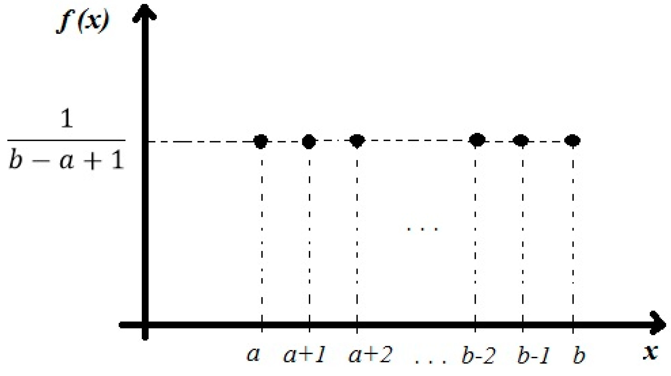
In Equation (14), the discrete uniform distribution should be used to generate discrete random values. The probability mass function graph of the discrete uniform distribution is shown in
Figure 3.
The probability function
should be used as represented in Equation (19) to map a discrete search space. Therefore, Equation (16) is modified to Equation (20) for the space projectile position at step + 1, which shows a decreasing probability of changing the position of the projectile for increasingly small spaces [
31].
Equation (18) should be modified to Equation (21) for the lead projectile position at step + 1.
where r1 and r2 are random numbers.
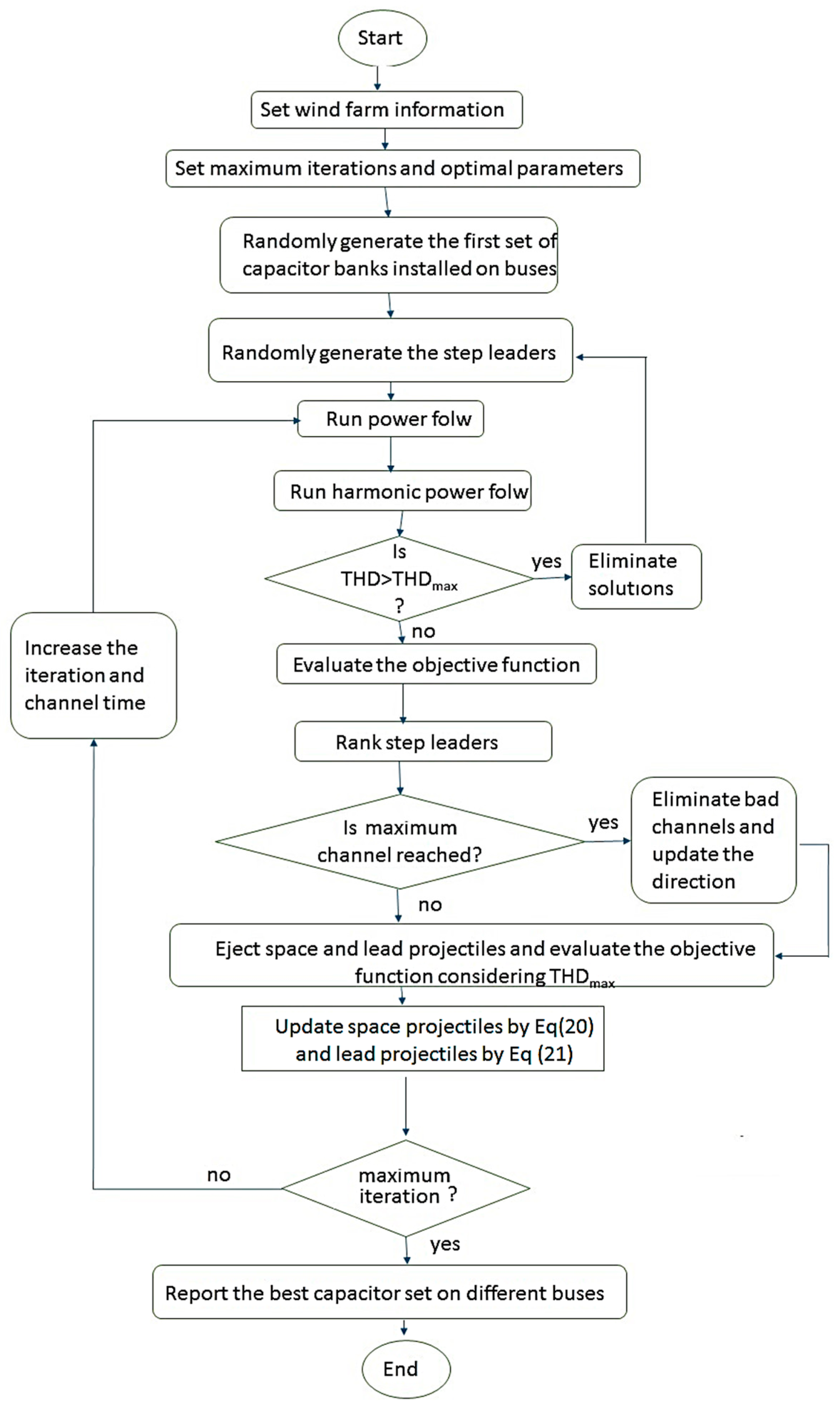
The procedures applied in this study for calculating the power flow and the harmonic power flow in the distribution system are presented in detail in [
32]. The procedures for the proposed DLSA method for optimal capacitor placement in wind farms considering harmonics are shown in
Figure 4 as a flowchart.
5. Case Study and Results
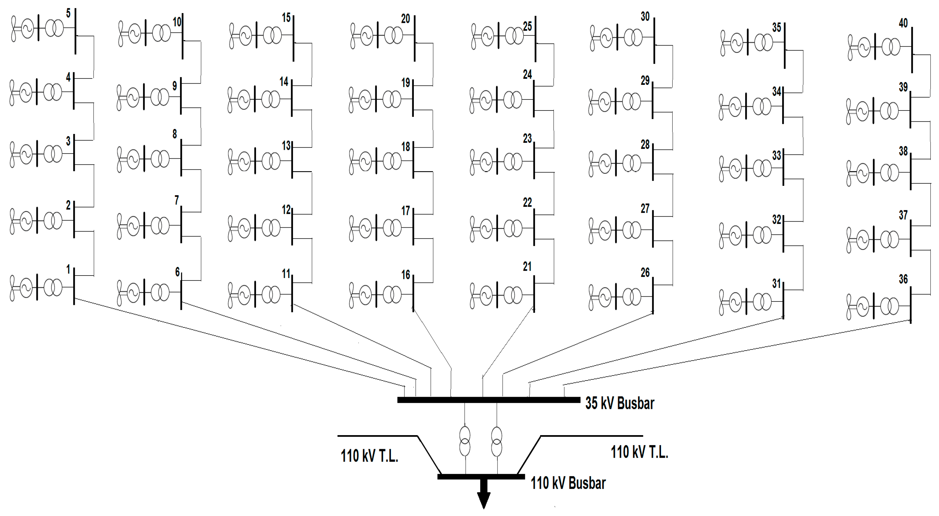
This proposed method was implemented in a case study of an 80-MW wind farm in Kosovo using the “Shtime” project, as presented in [
33]. The model of the distribution network is shown in
Figure 5. The required data from wind turbine generators, wind turbine transformers, substation transformers, and cables are presented in detail in [
33].
In the present wind farm system, 40 wind turbine generators, each rated at 2 MW, are individually connected to a 690-V bus that connects to the internal distribution network through 0.69/35 kV step-up transformers. The internal grid has eight sections with five wind turbines in each section. Within these sections, the wind turbines are connected through 35-kV underground cables of different lengths and capacities. In this study, assuming that the Transmission System Operator defines the voltage limitations of the wind farm on the high voltage side, overvoltages on the distribution network are avoided. The voltage constraints in each bus are considered to range from 0.9 to 1.1 per unit.
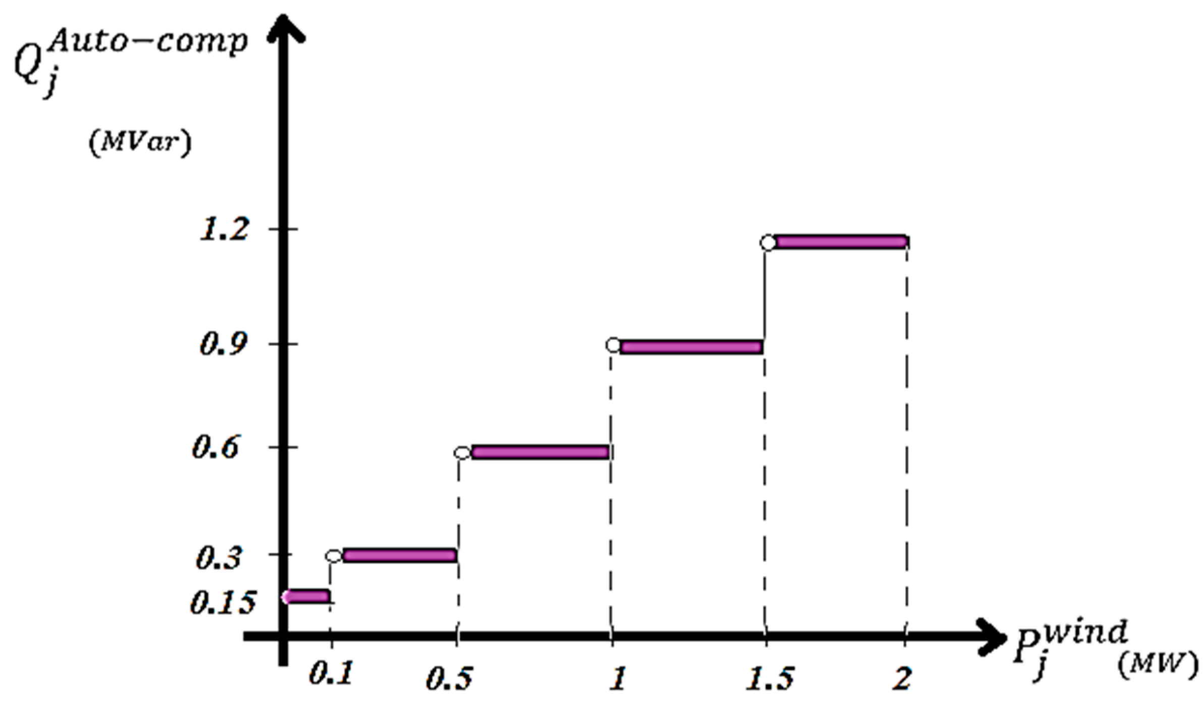
An automatic compensation system to compensate the reactive power absorbed by the wind turbine generators was considered in this study according to the operational scheme, as shown in
Figure 6. According to
Figure 7, specific amounts of reactive power, expressed as
, are injected to bus
j per power factor correction and Var compensation, which depend on the wind power
at that bus. This automatic compensation is definitely insufficient, for which additional support capacitors must be installed.
According to site information, the wind speed of the region rarely exceeds 15 m/s. The automatic compensation is only acceptable for wind speeds of less than 8 m/s. Therefore, for this study, a necessary compensation based on wind speeds of 8 to 15 m/s was considered.
Assuming a life expectancy of five years, the yearly depreciations of Xa and Xb were estimated to be Χa = $1.1 and Χb = $0.02. The average price of unsold energy can then be used to estimate the cost of energy loss when considering that Χe = 0.140 $/kWh. The investment cost of the first capacitor, including the cost of equipment and protection, is thus calculated to be $1500. The selection of capacitor size is limited to the standard sizes of 150, 300, 450, 600, 750, 900, 1050, and 1200 kVar. The optimal size can be determined through a discrete optimisation for each bus so that Qc = Nc × 150 (kVar), wherein Nc = 0, 1, …, 8.
First, the proposed DLSA method was applied to the case system without considering harmonics. The results of optimal capacitor placement at different buses of the wind farm at distinct wind speeds is presented in
Table 1. The maximum capacitor size to be installed at suitable buses is presented in the last column of
Table 1, while the total size of the capacitors installed at all buses given different wind speeds is shown in the last row of
Table 1. The value of the solution vector for some buses was zero, for which it would not be necessary to install capacitors at these buses.
Table 2 shows the results of optimal capacitor placement based on the DLSA. The total power loss and cost per distinct wind speeds according to radial power flow are compared with the results of three cases before capacitor placement, using the genetic algorithm (GA) as presented in [
9], and the discrete harmony search algorithm (DHSA) as presented in [
34]. As observed, the power loss and also the total cost at all considered wind speeds reduced significantly in comparison to before capacitor placement. Although an investment must be made to install additional capacitors, the total cost is proportional to the cost of power and energy losses; thus, a significant savings is obtained after capacitor placement. On the other hand, the results of the DLSA in terms of reduction in power loss and total costs appear to give lower figures than those calculated using GA and DSHA. Even so, the figures confirm the acceptable performance of the proposed DLSA in solving this problem.
Based on the harmonic power flow presented in [
32], the harmonic distortion of voltage in each bus after capacitor placement was calculated. As even and triplen harmonic orders are often not present in wind power plants; the harmonic orders
h = 5, 7, 11, 13, 17, 19, and 23 were considered, and the equivalent circuit in
Figure 3 was applied.
Table 3 shows the rate of total harmonic distortion at the different buses of the network. As can be observed, after capacitor placement,
THD at most buses and at different wind speeds is quite high, so the harmonics problem appears to be significant and should not be ignored.
In considering the harmonics and defining the limitation for
THD that the voltage of each bus should not exceed 5%, this problem was solved based on both radial power flow and harmonic power flow, and the results are shown in
Table 4. If we compare the results of
Table 1 and
Table 4, which disregard and consider harmonics, respectively, we find that the suitable buses for capacitor placement are quite different. Also, capacitor sizes at different wind speeds as well as the maximum capacitor size on each bus differ. The most important difference between the results of
Table 1 and
Table 4 can be found in the last row, which shows the total capacitors installed on the system given differing wind speeds. These values are largely affected by the objective function. Upon considering harmonics, a greater total kVar is required, and larger capacitors must also be installed.
A comparison of the results for optimal capacitor placement in a wind farm according to three different optimisation techniques and the harmonics of the system are presented in
Table 5. The total power loss in this case includes the two components of fundamental and harmonic power loss, as shown in Equation (9). For this reason, the power losses in
Table 5 are higher than those in
Table 2. Consequently, the total costs in
Table 5 are greater than the total costs in
Table 2.
Table 5 demonstrates that a consideration of harmonics can lead to optimal capacitor placement for reducing power loss and total costs, and that the results using DLSA are superior to those of the other optimisation techniques considered in this study. In addition, greater power and energy losses are evident upon considering harmonics, which will require larger capacitor sizes to mitigate losses; even so, total costs will be reduced and will lead to potentially significant savings. Although total cost, power loss, and total kVar installed on different buses increase under the abovementioned considerations, the
THD of bus voltages was controlled to remain below 5%, as shown in
Table 6. The effect of harmonic distortion was minimised, and these results are more reliable and practical.
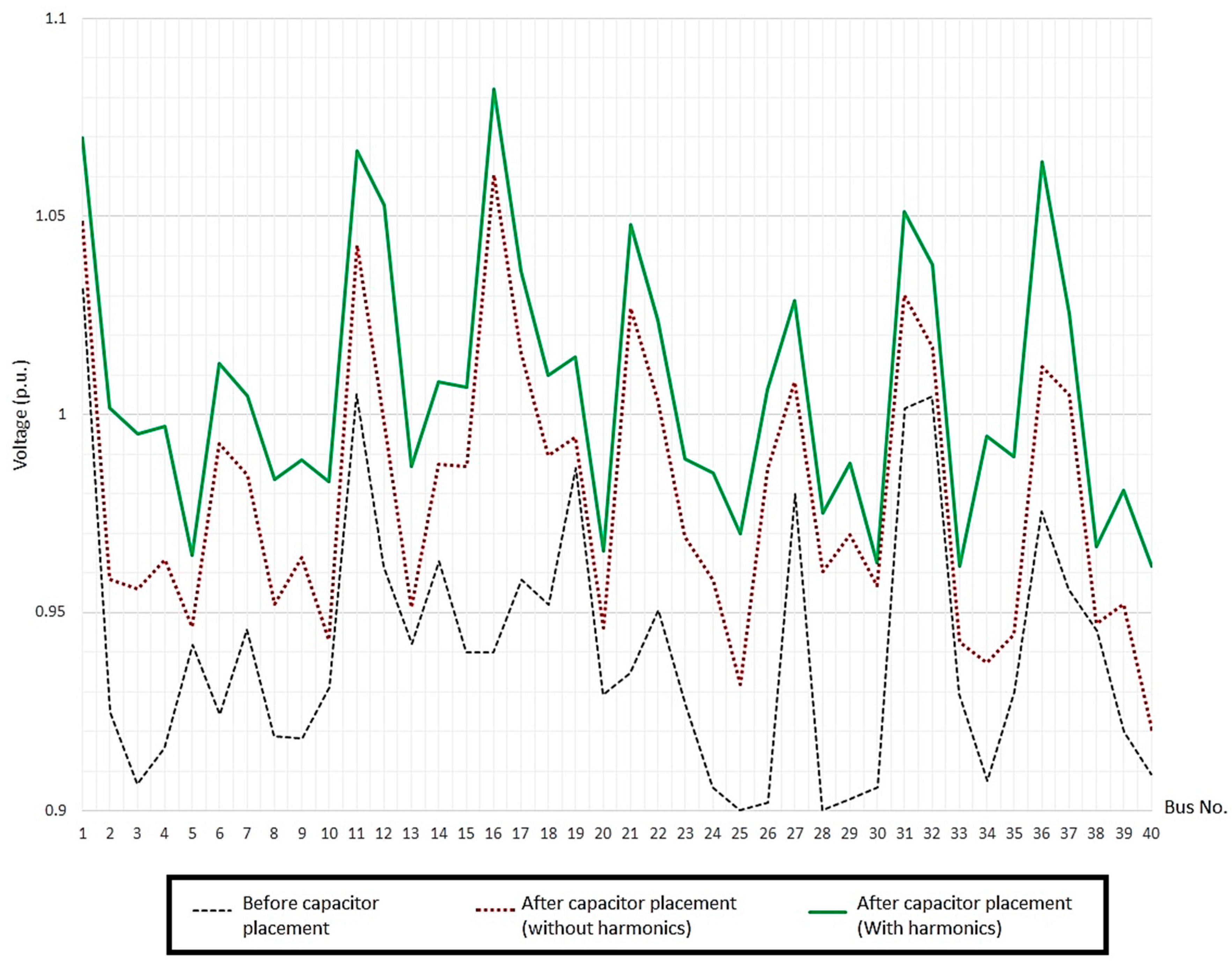
In order to validate the results, the voltage profile of wind farm for 10 m/s wind speed is obtained and are shown in
Figure 6. Three cases of before capacitor placement, after capacitor placement neglecting harmonics and after capacitor placement considering harmonics have been considered and all bus voltages are compared. Obviously, capacitor placement improves the voltage profile and the results of the proposed algorithm with considering harmonics are much better than the case without harmonic consideration.
The bus voltage imbalance ratio for three cases of before capacitor placement, after capacitor placement neglecting harmonics, and after capacitor placement considering harmonics, are computed and compared in
Table 7. A lower value of voltage imbalance ratio shows a better balance in system and can be expressed by [
35]:
where VUR is the voltage imbalance ratio and
are three-phase line voltages of bus
j.
can be calculated as:
For calculating any voltage in harmonic analysis, all harmonic orders should be included as:
Table 7 shows that the total voltage imbalance ratios for all of the wind speeds have been significantly reduced after capacitor placement. In addition, the results of voltage imbalance ratio (VUR) reduction in the case of capacitor placement considering harmonics are better than the results of the case without harmonic consideration.
The most suitable optimal parameters that produce the lowest fitness function value with the best convergence were selected for all of the considered optimisation techniques and are shown in
Table 8.
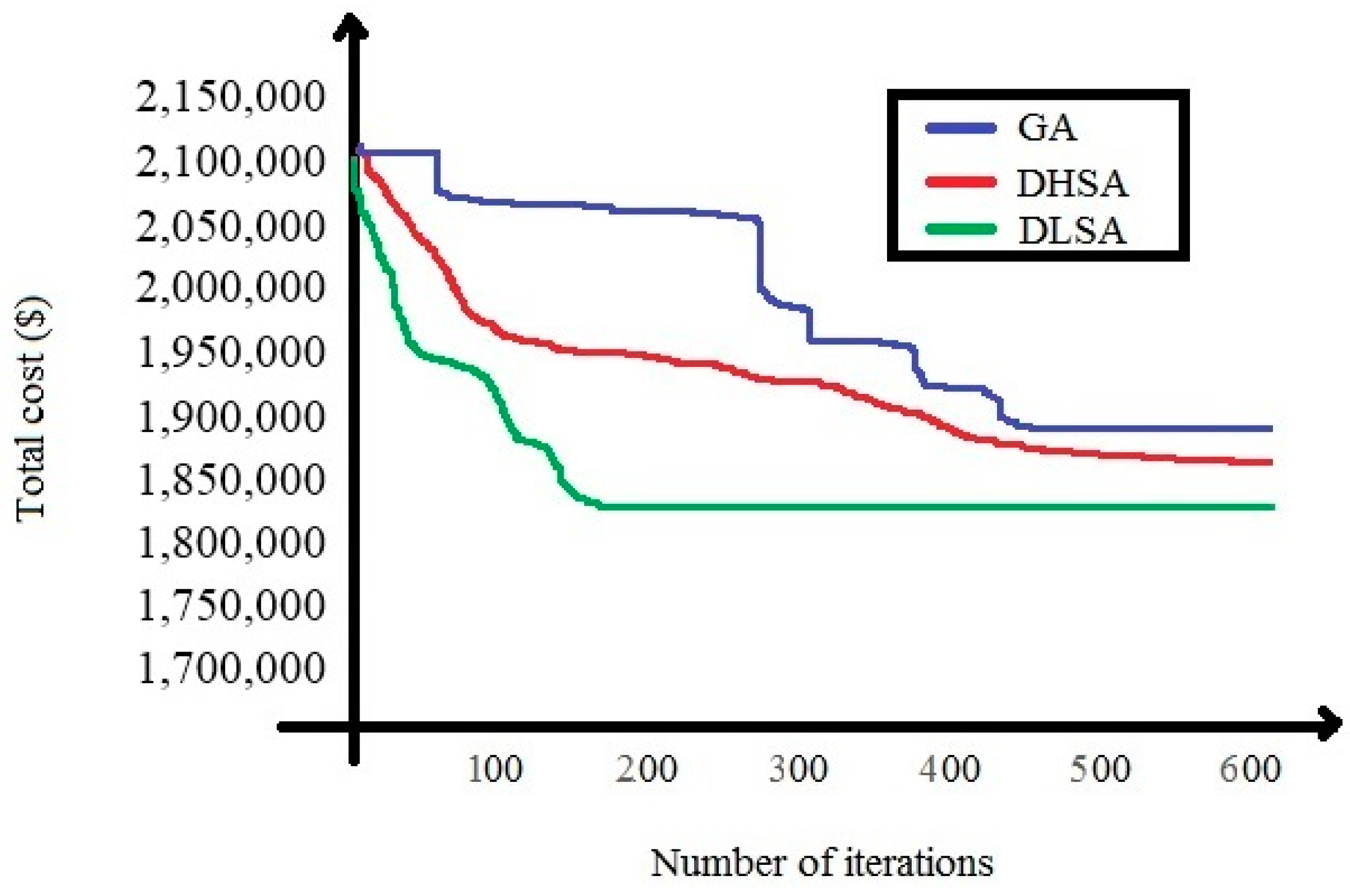
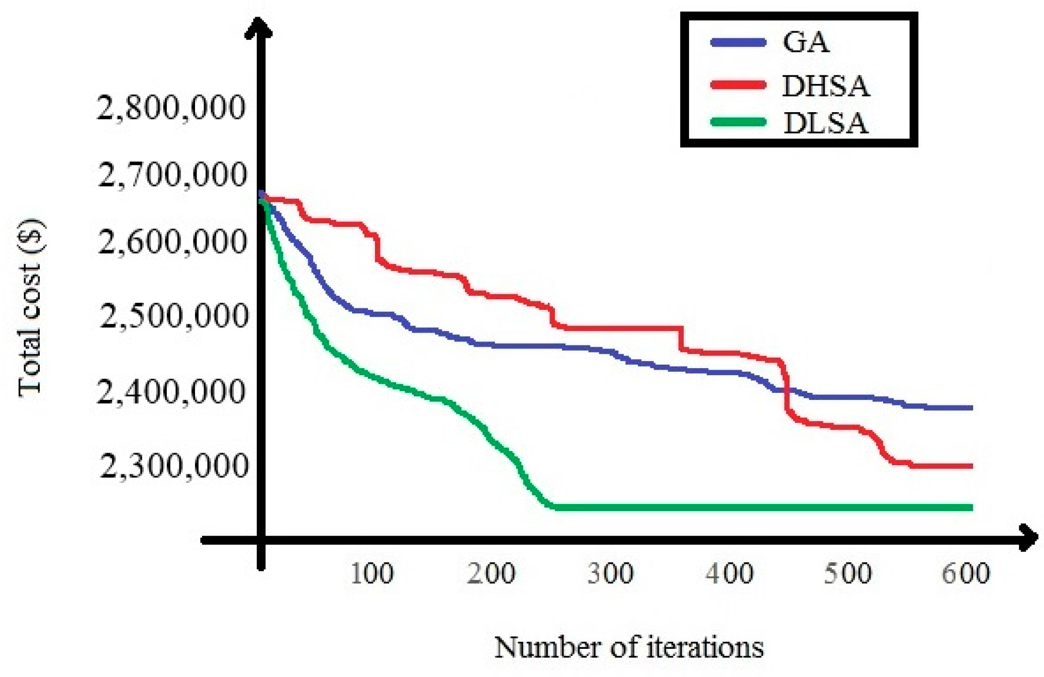
Finally, the convergence characteristics of all three optimisation techniques for determining optimal capacitor placement in a wind farm were evaluated at different wind speeds.
Figure 8 and
Figure 9 compares the convergence characteristics of different methods either considering or disregarding harmonics at a wind speed of 15 m/s. As seen in both cases, the proposed DSLA has better performance, gives the lowest objective function and shows faster convergence.


