Article

Seismic Vibration Control of 3D Steel Frames with Irregular Plans Using Eccentrically Placed MR Dampers

1
Department of Civil Engineering, Tongji University, Shanghai 200092, China
2
Faculty of Civil Engineering, University of Tabriz, Tabriz 5166616471, Iran
*
Author to whom correspondence should be addressed.
Sustainability 2017, 9(7), 1255; https://doi.org/10.3390/su9071255
Submission received: 23 May 2017 / Revised: 5 July 2017 / Accepted: 11 July 2017 / Published: 18 July 2017

Abstract

:
There has been a significant increase in attention toward designing smart structures and vibration control of structures in recent decades, and numerous methods and algorithms have been developed and experimentally investigated. However, the majority of these studies used the shear frame models to represent structures. Since the simplified models do not reflect the realistic behavior of those structures with irregularity in plan and elevation, the traditional methods for designing an optimal control that guarantees a desirable performance is impossible. In this study, the behavior of a 10-story irregular steel frame building is investigated with and without controlling systems. Two pairs of eccentrically placed MR dampers on each story are used in order to mitigate the coupled translational–torsional vibration. The controlling forces are determined using active, passive-off, passive-on, and clipped optimal controls based on the linear quadratic regulator (LQR) algorithm. The results demonstrate that using pairs of magneto-rheological (MR) dampers with an appropriate distance on lower story levels significantly reduces the inter-story drifts for the corner columns, as well as the roof displacements and accelerations.

1. Introduction

Numerous studies have been carried out in order to investigate the pre- and post-earthquake performance of civil infrastructures under different ground motions including several historic earthquakes such as 1940 El Centro, 1994 Northridge, 1995 Kobe, and 1999 Chi-Chi [1,2,3,4]. Recent studies have shown that the traditional approaches to designing earthquake resistance buildings, by using strong materials or by increasing the cross-sectional area of structural members, do not guarantee the desired performance for future earthquakes. Ghodrati Amiri et al. [5] showed that even with the advances in understanding the characteristics of the ground motions, as well as the nonlinear behavior of structural materials, the minimum damage level under the future unknown earthquake loads is not obtainable using conventional retrofitting techniques; thus, they proposed new configurations for retrofitting the existing steel frames. In particular, for those buildings with irregular designs in plan and elevation [6,7,8,9] advanced methods of vibration control are essential.
The majority of the research studies in the field of active and passive control of seismic vibrations focused on structures with symmetric designs, and the developed methods do not always meet the desired performance for irregular structures. Therefore, investigating the advanced methods for increasing the safety and serviceability of such buildings have gained significant attention in the last decade [10]. It is accepted that the nature of buildings is asymmetric due to structural and nonstructural components that cause eccentricity, and consequently, translational–torsional vibration under bidirectional earthquake loads. Although a significant number of studies have been carried out on seismic performance of structures under unidirectional excitations, and by using the independent shear frame models in two directions [11,12,13,14,15], investigating the performance of irregular buildings requires bidirectional seismic loading, and earthquakes have arbitrary directions that can be represented by three components [15,16]. Using simplified shear models ignores the extreme cases for the corner columns that can undergo larger displacements, and may fail before the other internal columns. In addition, under larger inter-story drifts, the earthquake resistant elements of the external frames may behave nonlinearly [17,18,19].
Several techniques have been developed in order to suppress the structural vibrations induced by earthquakes, due to the advances in modern control engineering and by means of smart control devices such as magneto-rheological (MR) dampers, shape memory alloys (SMAs) wires, tuned mass dampers (TMDs), and base-isolators, which can be categorized into passive, active, semi-active, and hybrid systems [20,21,22,23,24,25,26,27]. There have been an increases in the attention toward the application of MR dampers in both research and practical application, because of their reliable and outstanding performance [28,29,30,31,32,33,34,35,36]. The performance of any control devices is directly related to the control algorithms that are designed for each specific case. Among the most popular algorithms, such as linear quadratic regulator (LQR) [37,38,39], linear quadratic Gaussian (LQG) [40], fuzzy logic control [41,42], proportional integral derivative (PID), sliding mode control [43], and H∞ control [44], LQR has gained a significant importance and attention for optimal design purposes [42]. Yoshida et al. [45] studied the translational and torsional motion of a two-story building using MR dampers. Kim and Adeli [46] also used hybrid control for a 3D high-rise building and suggested the application of LQR and LQG algorithms for feedback control.
Yoshida et al. [45] used MR dampers to control coupled translational–torsional vibration of a two-story irregular building. In another study, Kim and Adeli [46] recommended LQR and LQG control for high-rise irregular steel frames. Chandiramani and Motra [47] also used multiple MR dampers to control torsional vibrations of a building with an asymmetric plan. Thus, the location of dampers are critical for irregular buildings [48]. In this paper, the LQR algorithm is used in order to determine the optimal control force for a purely active control, and the clipped-optimal method is used for the semi-active control; in addition, passive-on with different constant voltages ranging from 0 to 9 volts are used to compare the performance of each method. A ten-story irregular building is selected for numerical simulations, and the effectiveness of the number of story levels with controllable MR dampers are also investigated.

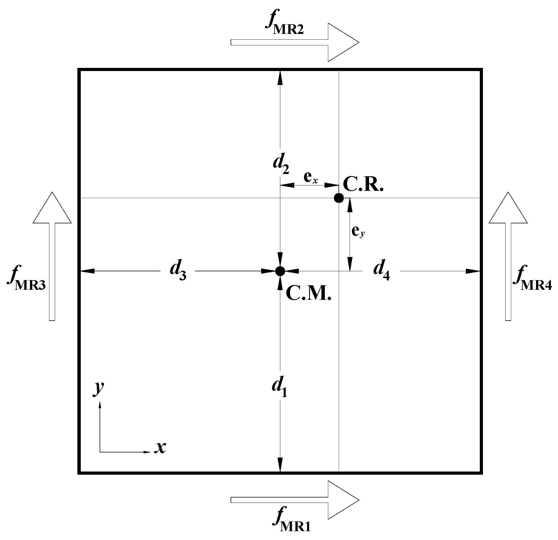
2. Governing Equations of Motion for the Controllable Building Using MR Dampers

Figure 1 demonstrates the location of the MR dampers schematically. In this figure, C.M. is the center of mass and C.R. is the center of rigidity, and each floor rotates about its center of rigidity. e x and e y are the eccentricities in the x and y directions, respectively. Each MR damper is placed with a distance of d i from the center of mass to create a torsional resisting moment about the vertical axis, which counteracts the torsional displacements imposed due to the eccentricity of the mass.
The governing equations of motion for a controlled n-degree-of-freedom (nDOF) system under earthquake load, x g ¨ , is expressed using (Equation (1)) [49]:
[ M ] { x ¨ ( t ) } + [ C ] { x ˙ } + [ K ] { x } = [ γ ] { u ( t ) } + { δ } x ¨ g ( t ) ,
which can be solved by rewriting (Equation (1)) in the state-space form as in (Equation (2)):
{ Z ˙ ( t ) } = [ A ] { Z ( t ) } + [ B u ] { u ( t ) } + { B r } x ¨ g ( t ) ,
where Z is the state vector, u is the input control force vector. A is the system matrix, and B u and B r are the input matrices (Equation (3))
{ Z ( t ) } = { x ( t ) x ˙ ( t ) } ;   A = [ [ 0 ] I M 1 K M 1 C ] ;   { B u } = [ [ 0 ] M 1 [ γ ] ] ;   { B r } = [ { 0 } [ M ] 1 { δ } ] .
Therefore, the first-order equation of motion in state–space form can be solved using the procedure that is explained in details by Azimi et al. [50] for a new semi-active control for braced frames. In (Equation (1)), {δ} is the coefficient vector for the earthquake ground acceleration, x ¨ g ( t ) , and [ γ ] represents the influence of the control devices on each degree of freedom, which can be defined as in (Equation (4)):
[ γ ] = [ D 1 D 2 D 2 D i D i D n D n ] ,
where D i is a (3 × 4) matrix for the ith story, which is defined as in (Equation (5)):
D i = [ 1 1 0 0 0 0 1 1 d 1 , i d 2 , i d 3 , i d 4 , i ] ,
The mass matrix, M , can be assembles as in (Equation (6)) [51]:
M = [ [ m 1 * ] [ 0 ] [ 0 ] [ 0 ] [ 0 ] [ 0 ] [ 0 ] [ m n * ] ] ,
where [ 0 ] is (3 × 3)-dimensional zero matrix that is defined as in (Equation (7)):
[ m n * ] = [ m n 0 0 0 m n 0 0 0 I z , n ] ,
where m n and I z , n are the mass and mass moment of inertia about z-direction of nth story, respectively. The mass moment of inertia about z-direction is defined as in (Equation (8)):
I z = j = 1 j m [ m j 12 ( a 2 + b 2 ) + m j [ ( x m , j X ¯ m ) 2 + ( y m , j Y ¯ m ) 2 ] ] ,
where, m x , j , and m y , j are the mass of jth slab in x and y directions, with coordinate of x m , j and y m , j , respectively. a and b are the dimensions of each slab, and ( X ¯ m , Y ¯ m ) is the coordinate of the center of mass of each story diaphragm. Stiffness of each story, [ k n ] , can be determined as in (Equation (9)):
[ k n ] = [ k x x 0 k x θ 0 k y y k y θ k θ x k θ y k θ θ ] ,
where:
k x x = j = 1 n k k x , j ,   k y y = j = 1 n k k y , j ,
k x θ = k θ x = j = 1 n k k x , j ( Y ¯ k y k , j ) ,
k y θ = k θ y = j = 1 n k k y , j ( X ¯ k x k , j ) ,
k θ θ = j = 1 j k ( k x , j ( Y ¯ y k , j ) 2 + k y , j ( X ¯ x k , j ) 2 ) .  
In the above equations, k x , j , and k y , j denote the stiffness of the jth column with coordinates of ( x k , j , y k , j ) . The center of rigidity is located at ( X ¯ k , Y ¯ k ) . Thus, the three-dimensional stiffness matrix for the building can be assembled as follows (Equation (14)):
K s = [ k 1 + k 2 k 2 k 2   k 2 + k 3 0   0 k 3   0 0   0 0   0 .. k n k n k n ] .
Considering an inherent damping of 5% for the first and fourth modes of vibration, the damping matrix of the system, Cs is determined using the Rayleigh method as follows (Equations (15) and (16)) [52],
C s = α M + β K
α = 2 ξ ω 1 ω 4 ω 1 + ω 4   β = 2 ξ ω 1 + ω 4
where ω 1 and ω 4 are the first and forth natural frequencies of the building, and ξ is the damping ratio.

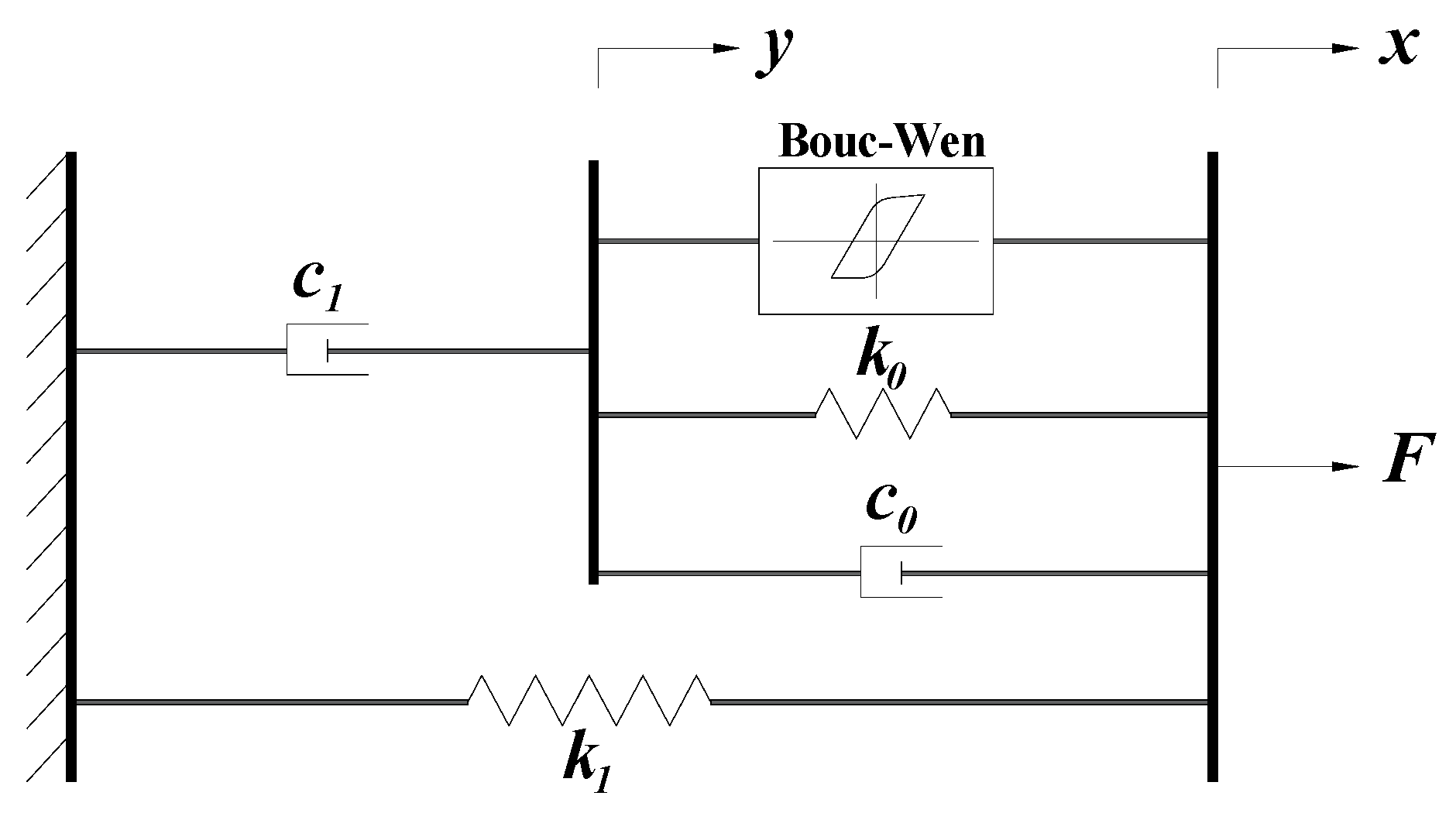
3. Magneto-Rheological (MR) Damper

The nonlinear behavior of a SDOF system was first described by Bouc [53] in 1967, and in 1997, Dyke et al. [54] proposed a phenomenological model for MR damper using Bouc–Wen model. The proposed model by Dyke et al. [54] showed that it can accurately estimate the force-displacement relationship of a MR damper, however, with less accuracy for low velocities. Since the behavior of a MR damper highly depends on the applied voltage, it is essential for a control strategy to accurately estimate and adjust the command voltage based on the measured responses.
The modified Bouc–Wen model of the MR damper is shown in Figure 2. The nonlinear force of a MR damper can be calculated using the following governing equations (Equations (17)–(23)):
F = c 1 y ˙ + k 1 ( x x 0 ) ,
y ˙ = 1 c 0 + c 1 + ( α z + c 0 x ˙ + k 0 ( x y ) ) ,
where F is the damper force, k 1 represents the accumulator stiffness. z is the evolutionary variable to describe the hysteretic deformation,
z ˙ = γ | x ˙ y ˙ | z | z | n 1 β ( x ˙ y ˙ ) | z | n + A ( x ˙ y ˙ ) ,
where γ and β are the shape parameters, and A describes the smoothness of linear to nonlinear transition.
The other voltage dependent parameters in (Equation (18)) are defined as a linear function of the efficient voltage, u [55,56] as follows:
α ( u ) = α a + α b u ,
c 0 ( u ) = c 0 a + c 0 b u ,
c 1 ( u ) = c 1 a + c 1 b u .
The efficient voltage, u , is calculated using a first order filter to consider the dynamics of rheological equilibrium of the MR fluid.
u ˙ = η ( u v )
In this study, the total 14 model parameters of the MR damper are selected based on the models developed by Spencer et al. [51], which are given in Table 1.

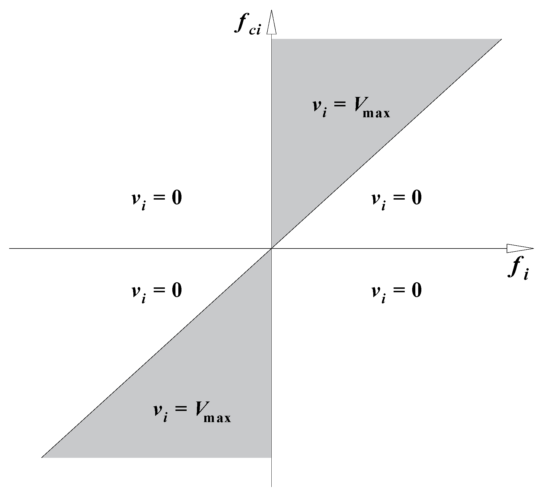
4. Active Control and Semi-Active Clipped Optimal Control Using LQR Algorithm

In this study, the control force of each MR damper is determined and applied to the structure by a clipped-optimal algorithm based on the linear quadratic regulator (LQR) through adjusting the input voltage. The LQR algorithm has been developed by Kurata et al. [57], and widely used in optimum control problems [37,38,39]. The LQR algorithm finds the optimal control force that can be applied using active actuators by minimizing the cost index, J, as follows (Equation (24)):
J = 1 2   0 ( { z ( t ) } T [ Q ] { z ( t ) } + { u ( t ) } T [ R ] { u ( t ) } )   d t ,
where z and u are the state response and input force vectors, respectively. In this study, the weighting matrices, Q and R , are selected as (Equation (25)):
Q = [ I n × n [ 0 ] [ 0 ] I n × n ] × 10 6 ,   R = [ I n × n ] × 10 5
where, n are the total number of DOFs; for those story levels without MR dampers, the corresponding elements of Q matrix are set to be zero. Therefore, the optimal control force vector, u o p t , for an active control is calculated as (Equation (26)):
{ u o p t ( t ) } = [ G ] × { z ( t ) }
where [ G ] is the gain matrix that is defined as (Equation (27)):
[ G ] = [ R ] 1 [ B ] T [ P ] ,
in which P is the Riccati matrix. Using the clipped-optimal algorithm, the input voltage of the MR damper, v i , can be obtained as (Equation (28)):
v i = V max H ( { f c i f i } f i ) ,
where V max is the saturation level of the input voltage, and H ( . ) is the Heaviside step function. Figure 3 illustrates the clipped-optimal control for selecting the command input voltage, the shaded region, of each MR damper.

5. Passive Control Using MR Dampers

In addition to the active and semi-active control strategies using LQR algorithm, the passive-on and passive-off control methods are also used in order to compare the performance of each controller effectively. Thus, the input voltage for each MR damper is set to be constant for three cases with 0 volt for the passive-off, and 5 and 9 volts for the passive-on methods.

6. Numerical Studies

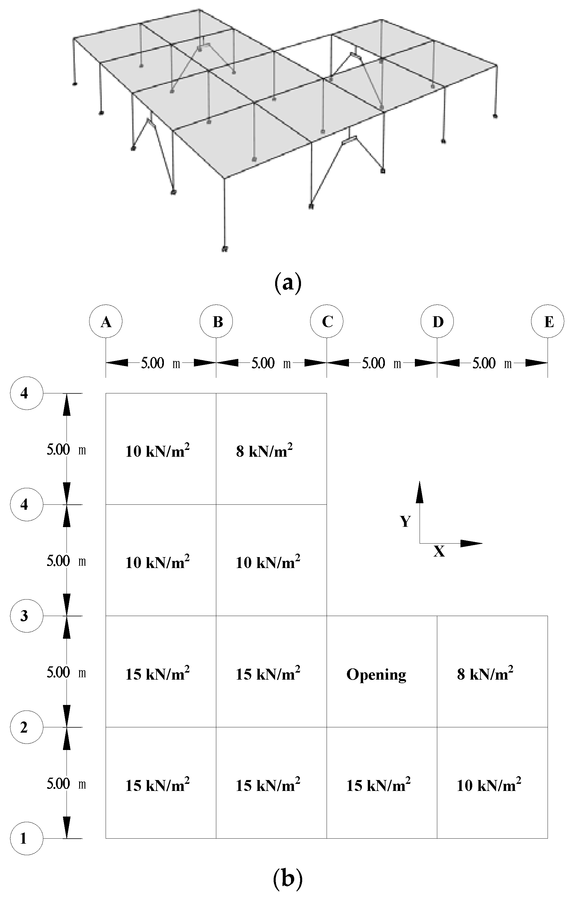
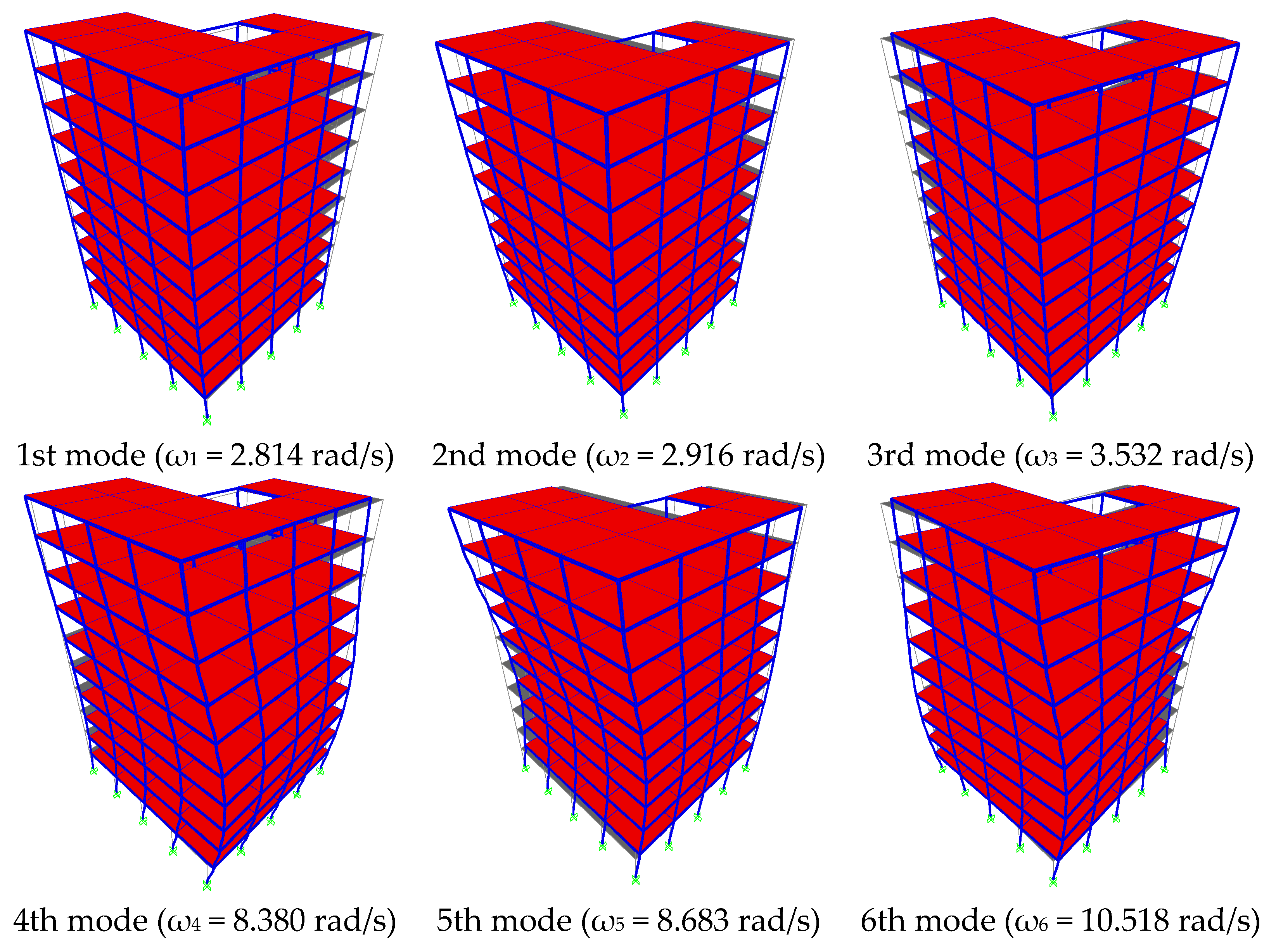
6.1. 10-Story Irregular Steel Moment Framed Building

Kaveh et al. [58,59] showed that irregular tall buildings need to be designed with careful considerations, and eccentricities are the main factor for estimating the stress level in external frames for optimal design purposes. In this study, in order to establish the numerical time–history analyses, a ten-story irregular building is modeled based on the studies carried out by the authors of [58,60]. The plan view and the 3D view of the 10-story building model, as well as the loadings, are shown in Figure 4. In order to idealize the model, it is assumed that all the columns have the same stiffness in both directions, and the floors are considered as rigid diagrams. Each story has 3.2 m height and 33,397 kg mass, and the stiffness of each column is 605,391 N/m. The position of each damper does not change in plane, but four cases of MR damper arrangements are considered in this study:
-
Case I with dampers installed on the 1st floor;
-
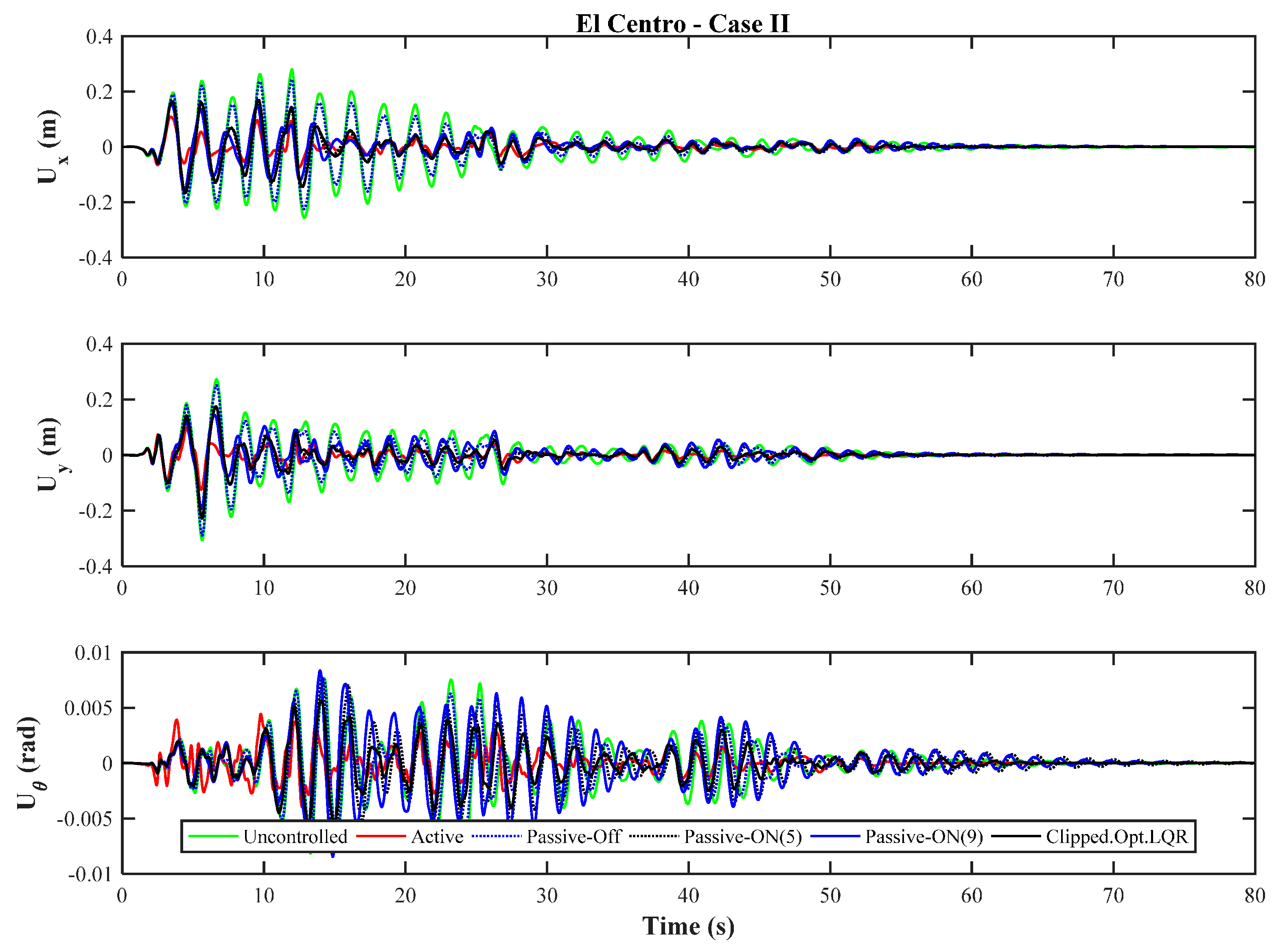
Case II with dampers installed in 1st–2nd floors;
-
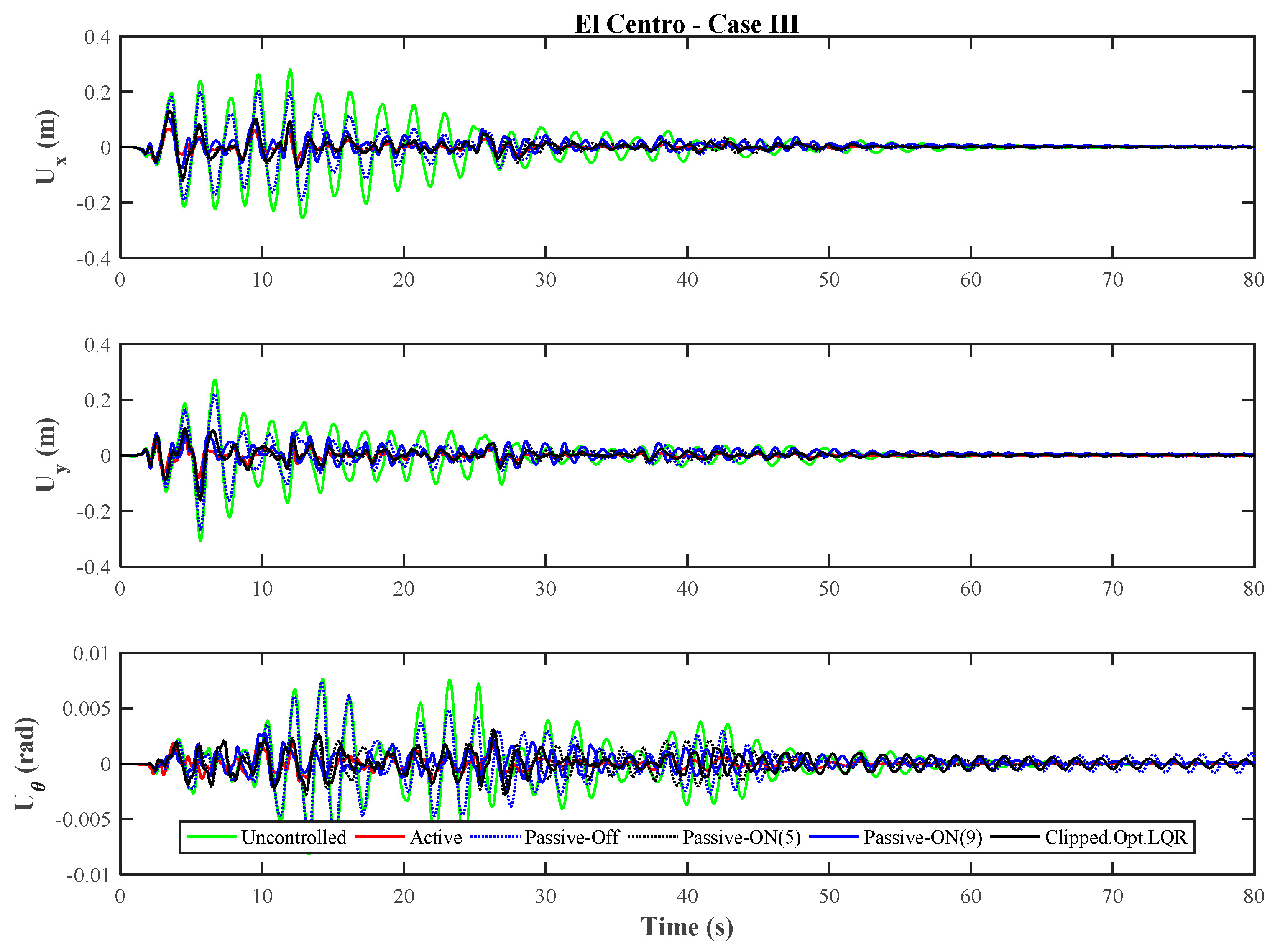
Case III with dampers installed in 1st–5th floors;
-
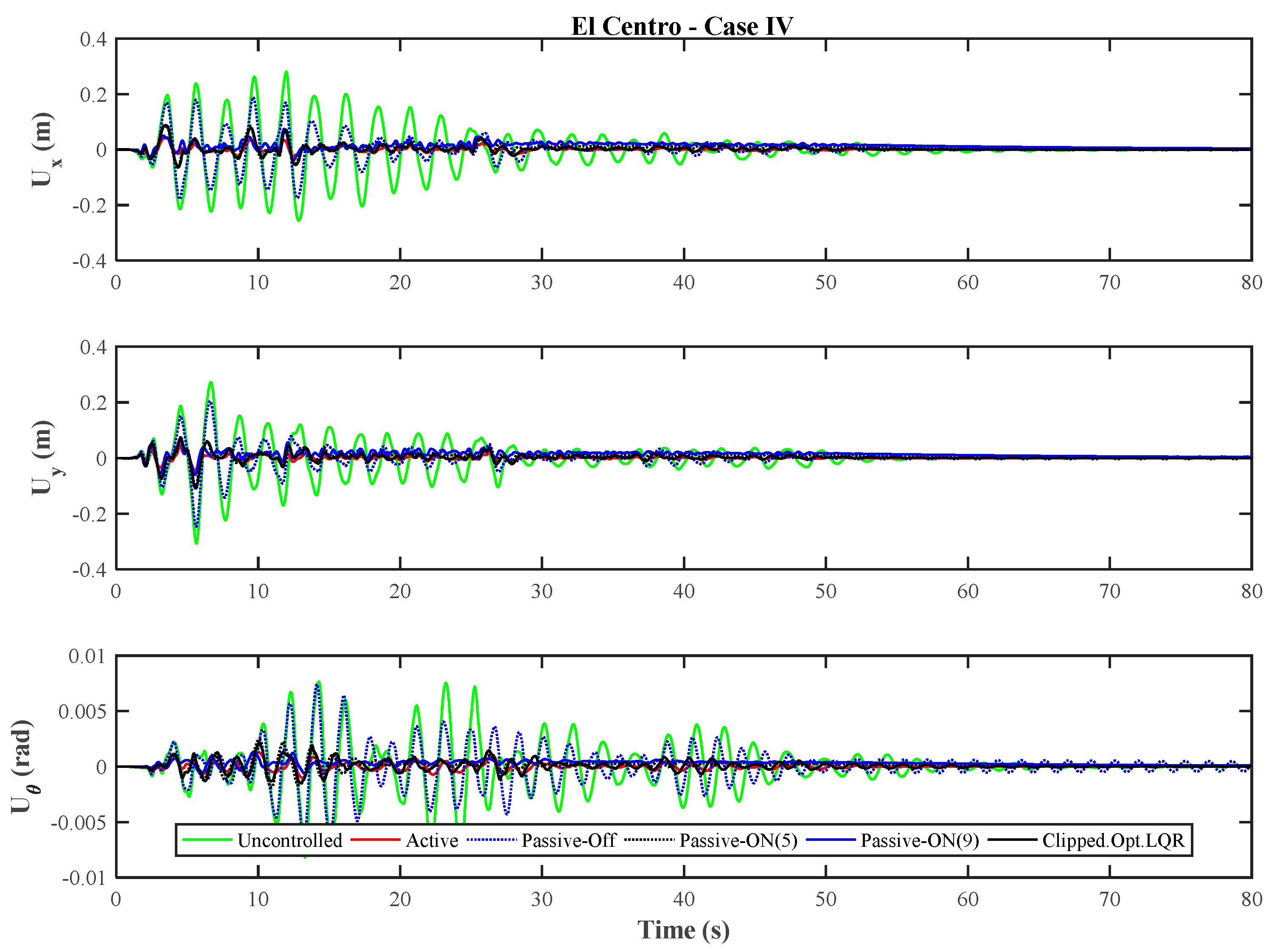
Case IV with dampers installed in all stories.

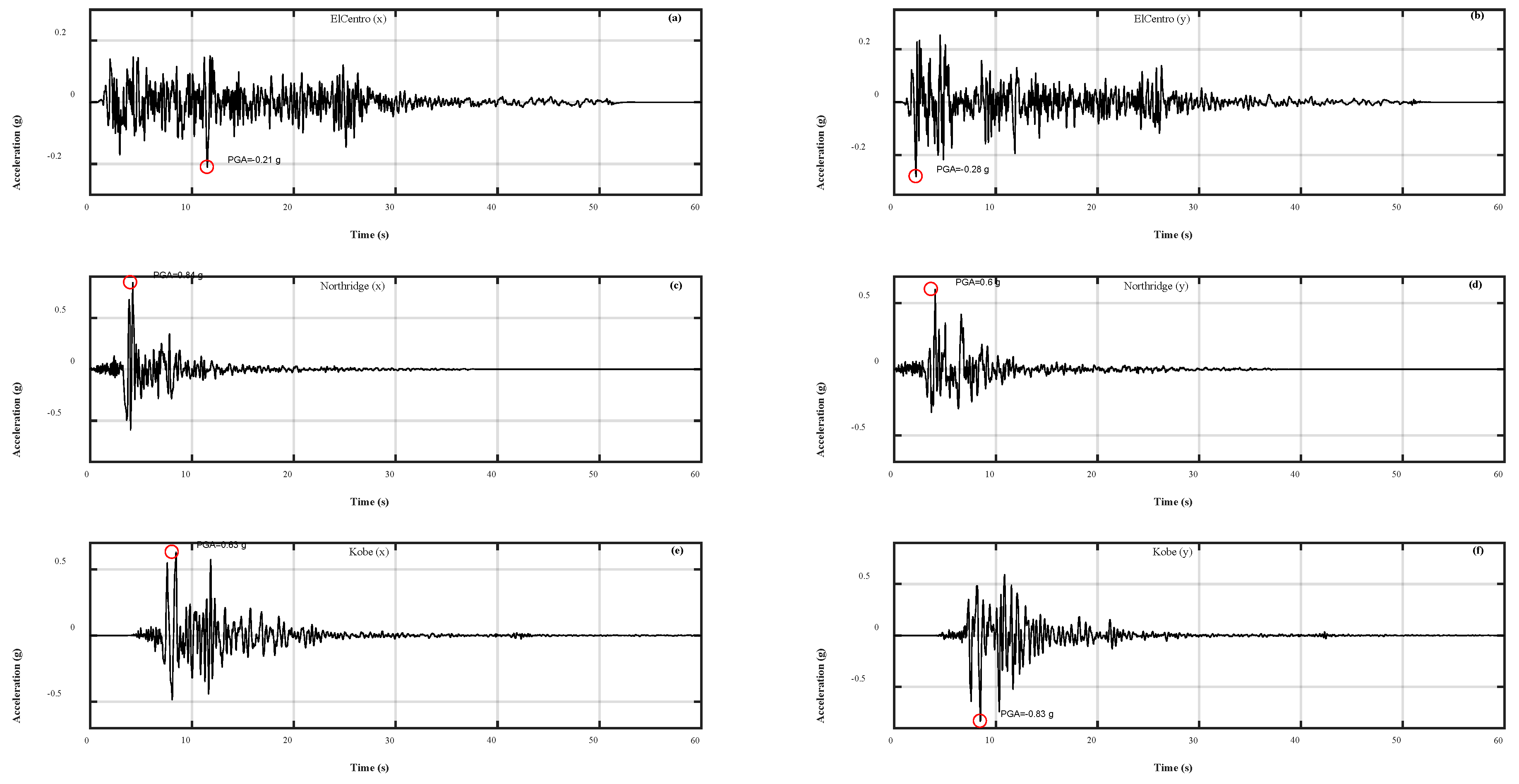
6.2. Earthquake Loads

Three of the most commonly used earthquake records in vibration control are selected in this study to evaluate the performance of each control techniques using MR dampers (Table 2). The elastic acceleration response spectra of the selected earthquakes are plotted in Figure 5. In this figure, X, and Y indicate the directions of the applied earthquake loads. In addition, the time–history of the earthquakes are given in Figure 5.

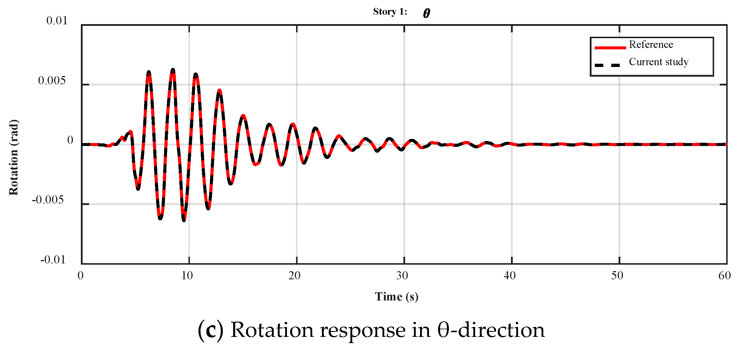
6.3. Calibration of the Numerical Simulation

To guarantee the accuracy of the results, and to validate the numerical simulation method, the same example from the study conducted by Nazarimofrad and Zahrai [61] was selected and the responses of the building at the first level for the uncontrolled system are compared with the current study in Figure 6. From the figure, the results are identical, and therefore, the current simulation method is valid and reliable.

7. Results and Discussion

For an irregular building, the higher modes have a significant contribution to the response of the structure under earthquake excitations. The modal analysis of the building is carried out to investigate the primary shape modes. The results of the modal analysis for the bidirectional lateral loads are shown in Figure 7. The initial shape of the building is also shown in gray color. The first six modes of vibration support the idea that the performance of the designed controllers needs to be evaluated under bidirectional earthquake loads. In this study, the number of controllers and the effectiveness of each story on the overall performance of the system is investigated. Since, most of the vibration modes include the couple translational–torsional motion, placing the control devices with the maximum eccentricity can be an advantage for such systems.

7.1. Maximum Responses

The maximum responses of the uncontrolled building under the three historic earthquakes as well as the controlled ones using the active (using actuators and based on LQR), passive-off (input voltage is zero), passive-on (input voltage of dampers are constant and maximum), and the clipped-optimal controls are discussed in this section. For both active and clipped-optimal controls, the LQR algorithm is used and the saturation limit for the clipped-optimal control is 5 volts. Two passive-on controls are defined using two different input voltages of 5 and 9 volts.
From Table 3, Table 4, Table 5 and Table 6, using an active control strategy, the displacement responses are reduced significantly. For example, for the El Centro earthquake, the reductions are approximately 53%, 60%, 75%, and 85% for each case, respectively. These results indicate that using the case I or case II may satisfy the control requirements; however, for the Northridge and Kobe earthquakes, the maximum displacement ranges from 18% (case I) to 77% (case IV). Although using the passive-on control strategy with constant voltages of 5 and 9 volts results in very close responses for the El Centro earthquake, for the same buildings under Kobe and Northridge earthquakes, the differences are noticeable. For example, under the Northridge earthquake, passive-on control with 9 volts results in 20% more reduction compared to the same system with 5 volts of input voltage for each controller. Since the clipped-optimal controller switches the input voltage between the minimum and maximum saturation limits, it saves more energy compared to the passive-on cases, particularly, for weak ground motions or those with long duration but fewer peak accelerations, such as the Northridge earthquake. This statement about the energy of control can be proved using the method that has been introduced by Azimi et al. [50]. For all the cases, using the active control increases the maximum acceleration at roof level, while the other methods, particularly the clipped-optimal control, decrease the acceleration responses along with the displacements and rotations. In the case of power loss, the passive-off control with MR dampers still offers a considerable reduction in the responses from 7% to 32% depending on the configurations and the number of dampers.

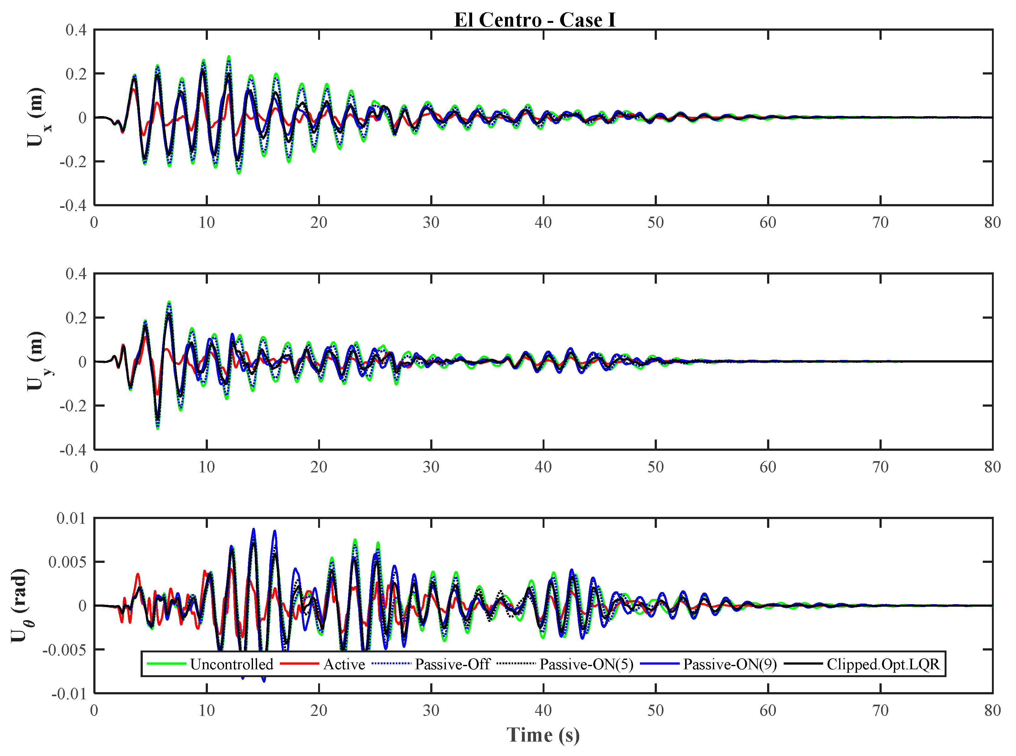
7.2. Time–History Responses

Using the active control for case I and II, the rotation in the beginning of vibration is increased, but later the reduction is significant. In addition, there are fewer limitations for generating the optimal control forces using active control; on the other hand, the generated forces for MR dampers dependent on the velocity and displacements of each damper shaft. As it is clear from Figure 8, Figure 9, Figure 10 and Figure 11, using the active control system under the El Centro earthquake, and with respect to the case I, the case II results in 15% more reduction, while the case IV reduces the responses by 70%. For the passive-on control system using the MR dampers, the reduction in the responses is not comparable with the active control when more stories are equipped with MR dampers. For example, under the Northridge earthquake, the active case II, III, and IV reduce the displacement responses by 12%, 40%, and 63% compared to the case I. However, the passive-on case II, III, and IV reduces the displacement responses by 4%, 15%, and 23% as compared to the case I.
In addition, for the Kobe earthquake the response history and the maximum responses confirm that most of the response reduction using MR dampers is achieved using the case I and II, while case III and IV are more effective if an active controller is employed. It is also noticeable that for the case I and II, the active control increases the rotational response in the beginning of the vibration while the rotation is not increased for the case III and IV with more actuators in the top story levels. Further, from the responses plots for the case III and IV, it can be said that active control is more successful as compared to the other controllers.

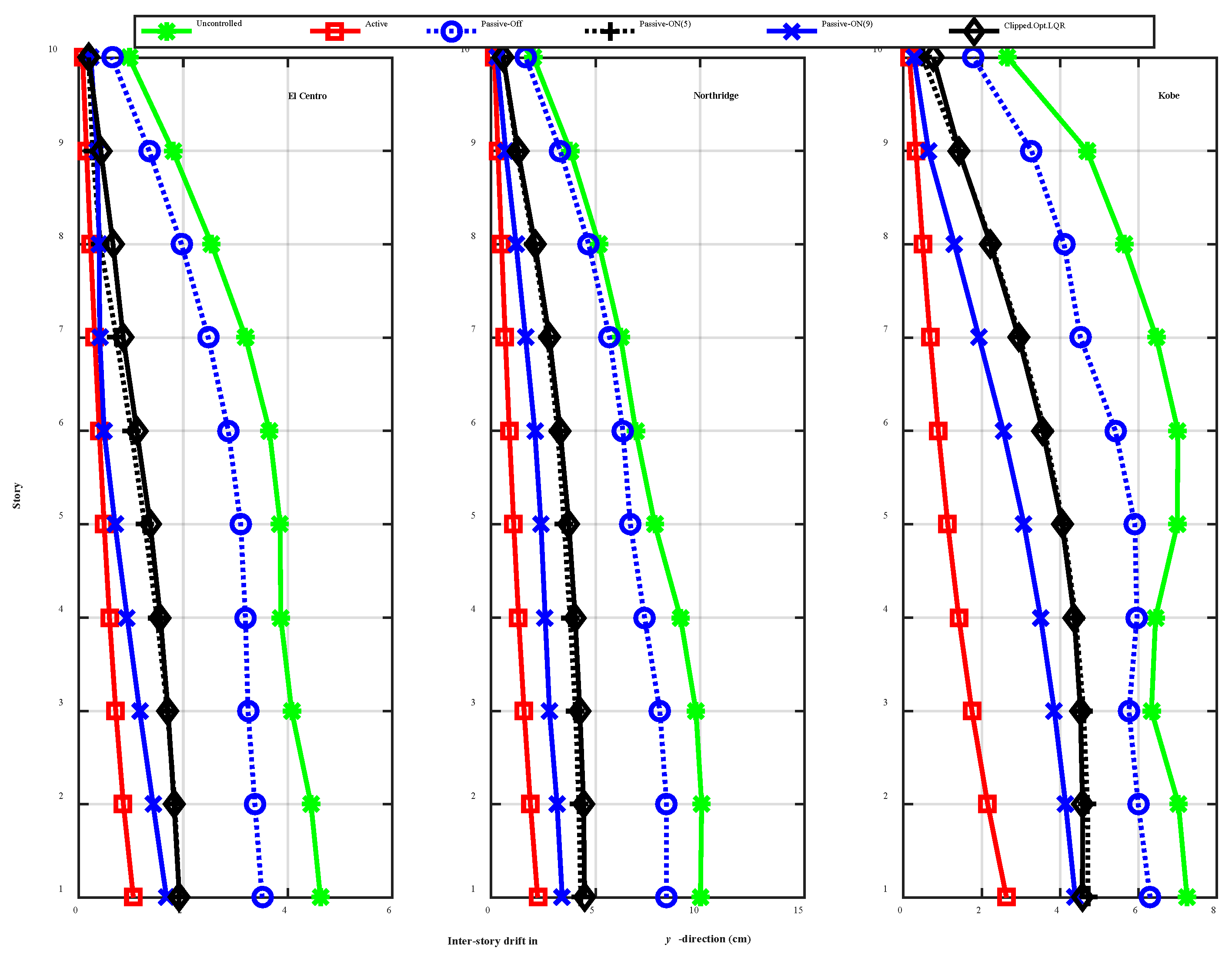
7.3. Maximum Inter-Story Drifts

The inter-story drift is an important measure of the shear force of a story level. Reduction in the inter-story displacements, particularly for the lower stories, can decrease the P-Δ effects and nonlinear behavior of the corner columns, which may not be possible to be considered in a simple control algorithm. Figure 12 and Figure 13 show the maximum inter-story drift profiles for the corner columns of the building in two directions. The inter-story drifts are larger in the lower stories, and the upper story columns may remain elastic during an earthquake. Thus, it is critical to control the inter-story drifts for the first stories. As it is obvious from the figures, the most reduction occurs by using the active control and the passive-on method with 9 volts of the input voltage. By comparing the two passive-on controls, it can be said that the inter-story drift for both are very close to each other with respect to the uncontrolled building, and therefore, using a clipped-optimal control may require less energy of control, which is highlighted in the study by Azimi et al. [50]. Furthermore, the passive-off control reduces the inter-story drifts considerably, particularly for the El Centro and Kobe earthquakes, which increases the reliability of the clipped-optimal control in the case of power loss.

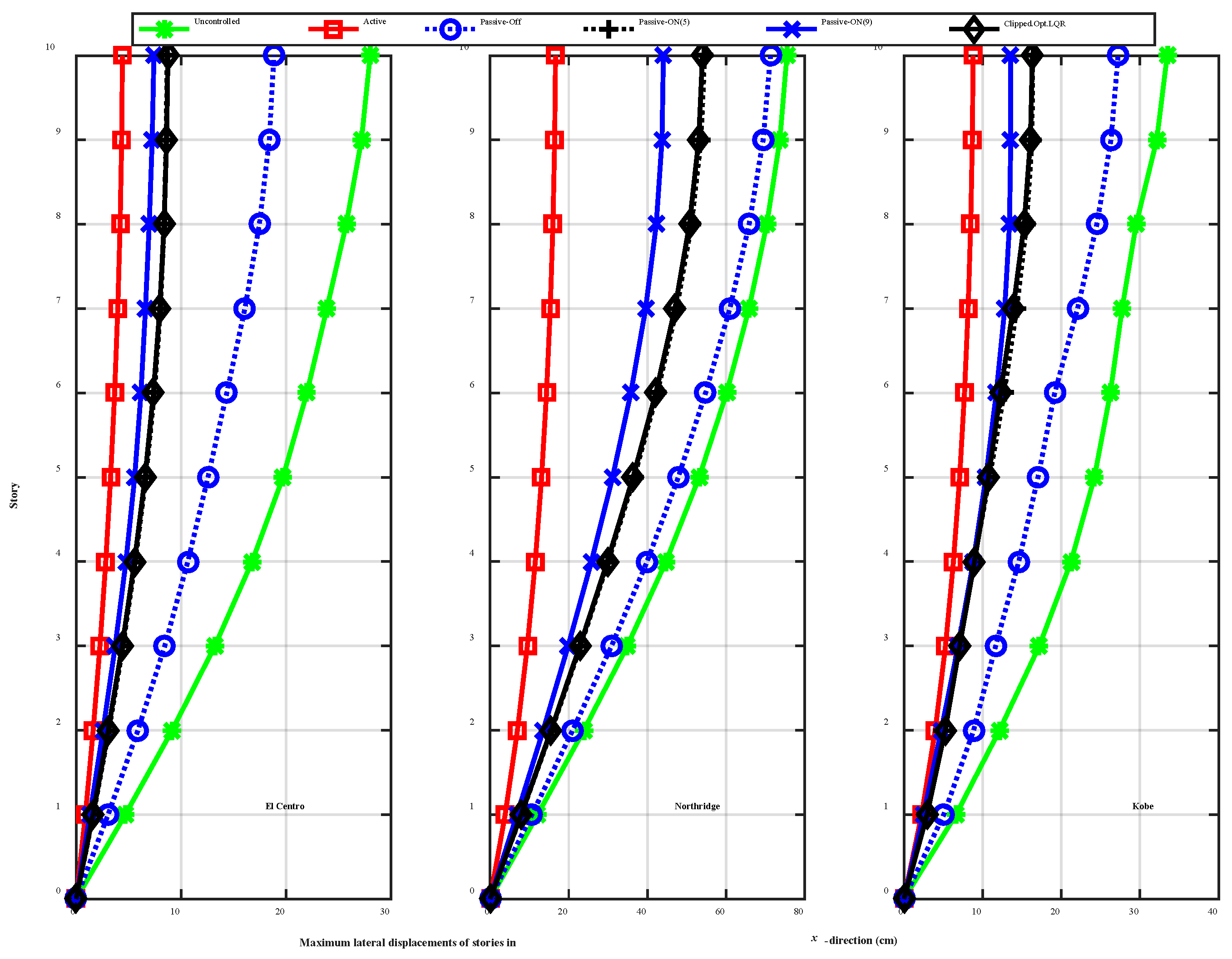
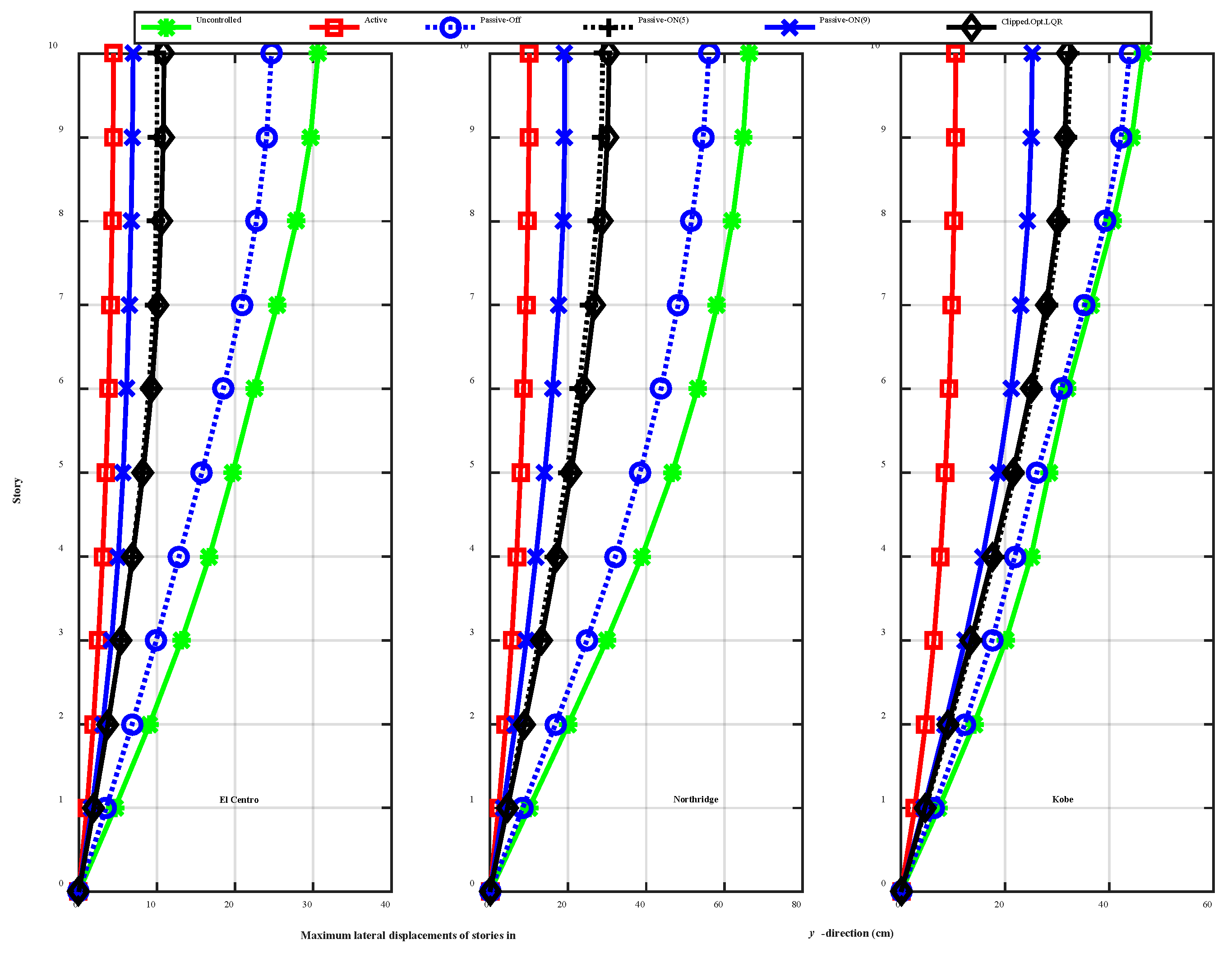
7.4. Maximum Lateral Displacements

For a better understanding and deep investigation of the performance of each control strategy for reducing the lateral displacements, the lateral displacements and rotation profiles in the x, y, and θ directions for the case IV are shown in Figure 14, Figure 15 and Figure 16. As it is evident from the figures, active control significantly reduces the maximum displacements, however, passive and clipped-optimal techniques are also effective in suppressing the translational-torsional motions of the building. The passive-off control method clearly shows the safety margin compared with the uncontrolled system, and therefore, using MR dampers are always reliable considering the unknown characteristics of the structure and ground motions.

8. Summary and Conclusions

In this paper, the popular control strategies are investigated for an irregular high-rise building. A purely active controller based on the linear quadratic regulator (LQR) is designed, and it is compared with the semi-active clipped-optimal control (with the same LQR algorithm) using MR dampers. In addition, two cases of passive-on and passive-off control methods are used in order to study the performance of each control techniques under different bidirectional earthquake loads. Furthermore, the influence of the number of controller devices are also studied. The results show that adding additional MR dampers on the upper levels does not reduce the responses effectively, as compared with the active control. Therefore, by considering the energy of control, as well as the performance in the case of power loss, time delay, or miscalculations, the clipped-optimal control is proved to be the suitable controller for irregular buildings. As part of the study, the future publications will address the experimental tests and practical implementations.

Author Contributions

This study was initiated at Tongji University, China, by Yuwen Hu and Lingfei Liu. The numerical simulations are carried out by Saeed Rahimi at the University of Tabriz, Tabriz, Iran. Yuwen Hu also wrote the manuscript that was revised several times by the co-authors. The figures and tables are provided by all the authors by performing several numerical analyses.

Conflicts of Interest

The authors declare no conflict of interest.

References

  1. Mosleh, A.; Rodrigues, H.; Varum, H.; Costa, A.; Arêde, A. Seismic behavior of RC building structures designed according to current codes. Structures 2016, 7, 1–13. [Google Scholar] [CrossRef]
  2. Mosleh, A.; Varum, H.; Jara, J.; Razzaghi, M.S. Development of fragility curves for RC bridges subjected to reverse and strike-slip seismic sources. Earthq. Struct. 2016, 11, 517–538. [Google Scholar] [CrossRef]
  3. Rashidi, M.; Takhtfiroozeh, H. Determination of Bond Capacity in Reinforced Concrete Beam and Its Influence on the Flexural Strength. Mech. Mater. Sci. Eng. 2016, 6. [Google Scholar] [CrossRef]
  4. Rashidi, M.; Heidari, M.; Azizyan, G. Numerical Analysis and Monitoring of an Embankment Dam During Construction and First Impounding (Case Study: Siah Sang Dam). Sci. Iran. J. 2017, in press. [Google Scholar]
  5. Amiri, G.G.; Azimi, M.; Darvishan, E. Retrofitting I-beam to double-I built-up column connections using through plates and T-stiffeners. Sci. Iran. Trans. A Civ. Eng. 2013, 20, 1695–1707. [Google Scholar]
  6. Gerist, S.; Maheri, M.R. Multi-stage approach for structural damage detection problem using basis pursuit and particle swarm optimization. J. Sound Vib. 2016, 384, 210–226. [Google Scholar] [CrossRef]
  7. Kaveh, A.; Bakhshpoori, T.; Ashoory, M. An Efficient Optimization Procedure Based on Cuckoo Search Algorithm for Practical Design of Steel Structures. IUST 2012, 2, 1–14. [Google Scholar]
  8. Kaveh, A.; Dadras, A. A guided tabu search for profile optimization of finite element models. Int. J. Optim. Civ. Eng. 2017, 7, 527–537. [Google Scholar]
  9. Kaveh, A.; Dadras, A. Structural damage identification using an enhanced thermal exchange optimization algorithm. Eng. Optim. 2017, 1–22. [Google Scholar] [CrossRef]
  10. Lin, J.L.; Tsai, K.C. Seismic analysis of two-way asymmetric building systems under bi-directional seismic ground motions. Earthq. Eng. Struct. Dyn. 2008, 37, 305–328. [Google Scholar] [CrossRef]
  11. Zhang, J.; Zeng, K.; Jiang, J. An optimal design of bi-directional TMD for three dimensional structure. In Computational Structural Engineering; Springer: Berlin, Germany, 2009; pp. 935–941. [Google Scholar]
  12. Kan, C.L.; Chopra, A.K. Elastic earthquake analysis of a class of torsionally coupled buildings. J. Struct. Div. 1977, 103, 821–838. [Google Scholar]
  13. Yanik, A.; Aldemir, U.; Bakioglu, M. A new active control performance index for vibration control of three-dimensional structures. Eng. Struct. 2014, 62, 53–64. [Google Scholar] [CrossRef]
  14. Nigdeli, S.M.; Boduroğlu, M.H. Active Tendon Control of Torsionally Irregular Structures under Near-Fault Ground Motion Excitation. Comput. Aided Civ. Infrastruct. Eng. 2013, 28, 718–736. [Google Scholar] [CrossRef]
  15. Cruz, E.F.; Cominetti, S. Three-Dimensional Buildings Subjected to Bi-Directional Earthquakes. Validity of Analysis Considering Uni-Directional Earthquakes. In Proceedings of the 12th World Conference on Earthquake Engineering, Auckland, New Zealand, 30 January–4 February 2000. [Google Scholar]
  16. Heo, J.S.; Lee, S.K.; Park, E.; Lee, S.H.; Min, K.W.; Kim, H.; Jo, J.; Cho, B.H. Performance test of a tuned liquid mass damper for reducing bidirectional responses of building structures. Struct. Des. Tall Spec. Build. 2009, 18, 789–805. [Google Scholar] [CrossRef]
  17. Tso, W.; Zhu, T. Design of torsionally unbalanced structural systems based on code provisions I: Ductility demand. Earthq. Eng. Struct. Dyn. 1992, 21, 609–627. [Google Scholar] [CrossRef]
  18. Zhu, T.; Tso, W. Design of torsionally unbalanced structural systems based on code provisions II: Strength distribution. Earthq. Eng. Struct. Dyn. 1992, 21, 629–644. [Google Scholar] [CrossRef]
  19. Correnza, J.; Hutchinson, G.; Chandler, A. Effect of transverse load-resisting elements on inelastic earthquake response of eccentric-plan buildings. Earthq. Eng. Struct. Dyn. 1994, 23, 75–89. [Google Scholar] [CrossRef]
  20. Mahtabi, M.; Shamsaei, N.; Mitchell, M. Fatigue of Nitinol: The state-of-the-art and ongoing challenges. J. Mech. Behav. Biomed. Mater. 2015, 50, 228–254. [Google Scholar] [CrossRef] [PubMed]
  21. Mahtabi, M.; Shamsaei, N. Multiaxial fatigue modeling for Nitinol shape memory alloys under in-phase loading. J. Mech. Behav. Biomed. Mater. 2016, 55, 236–249. [Google Scholar] [CrossRef] [PubMed]
  22. Mahtabi, M.J.; Shamsaei, N. A modified energy-based approach for fatigue life prediction of superelastic NiTi in presence of tensile mean strain and stress. Int. J. Mech. Sci. 2016, 117, 321–333. [Google Scholar] [CrossRef]
  23. Joghataie, A.; Dizaji, M.S.; Dizaji, F.S. Neural Network Software For Dam-Reservoir Foundation Interaction. In Proceedings of the International Conference on Mechanical, Automotive and Materials Engineering, Dubai, United Arab Emirates, 7–8 January 2012. [Google Scholar]
  24. Farrokh, M.; Dizaji, M.S.; Joghataie, A. Modeling hysteretic deteriorating behavior using generalized Prandtl neural network. J. Eng. Mech. 2015, 141, 04015024. [Google Scholar] [CrossRef]
  25. Dizaji, M.S.; Alipour, M.; Harris, D.K. Leveraging Vision for Structural Identification: A Digital Image Correlation Based Approach. In International Digital Imaging Correlation Society, Conference Proceedings of the Society for Experimental Mechanics Series; Philadelphia, PA, USA, 8–11 November 2016; Springer International Publishing: Basel, Switzerland, 2017. [Google Scholar]
  26. Farrokh, M.; Dizaji, M.S. Adaptive simulation of hysteresis using neuro-Madelung model. J. Intell. Mater. Syst. Struct. 2016, 27, 1713–1724. [Google Scholar] [CrossRef]
  27. Joghataie, A.; Dizaji, M.S. Neuroplasticity in dynamic neural networks comprised of neurons attached to adaptive base plate. Neural Netw. 2016, 75, 77–83. [Google Scholar] [CrossRef] [PubMed]
  28. Shook, D.A.; Roschke, P.N.; Ozbulut, O.E. Superelastic semi-active damping of a base-isolated structure. Struct. Control Health Monit. 2008, 15, 746–768. [Google Scholar] [CrossRef]
  29. Ozbulut, O.; Daghash, S.; Sherif, M. Shape Memory Alloy Cables for Structural Applications. J. Mater. Civ. Eng. 2015, 28, 04015176. [Google Scholar] [CrossRef]
  30. Spencer, B., Jr.; Nagarajaiah, S. State of the art of structural control. J. Struct. Eng. 2003, 129, 845–856. [Google Scholar] [CrossRef]
  31. Soong, T.; Spencer, B. Supplemental energy dissipation: State-of-the-art and state-of-the-practice. Eng. Struct. 2002, 24, 243–259. [Google Scholar] [CrossRef]
  32. Angeles, J.M.; Alvarez-Icaza, L. 3D identification of buildings seismically excited. IFAC Proc. Vol. 2005, 38, 327–332. [Google Scholar] [CrossRef]
  33. Gattulli, V.; Lepidi, M.; Potenza, F. Seismic protection of frame structures via semi-active control: Modeling and implementation issues. Earthq. Eng. Eng. Vib. 2009, 8, 627–645. [Google Scholar] [CrossRef]
  34. Lin, J.L.; Tsai, K.C.; Yu, Y.J. Bi-directional coupled tuned mass dampers for the seismic response control of two-way asymmetric-plan buildings. Earthq. Eng. Struct. Dyn. 2011, 40, 675–690. [Google Scholar] [CrossRef]
  35. Zhao, B.; Gao, H. Torsional vibration control of high-rise building with large local space by using tuned mass damper. Adv. Mater. Res. 2012, 446–449, 3066–3071. [Google Scholar] [CrossRef]
  36. Farghaly, A.A.; Ahmed, M.S. Optimum design of TMD system for tall buildings. ISRN Civ. Eng. 2012, 2012. [Google Scholar] [CrossRef]
  37. Amini, F.; Hazaveh, N.K.; Rad, A.A. Wavelet PSO-Based LQR Algorithm for Optimal Structural Control Using Active Tuned Mass Dampers. Comput. Aided Civ. Infrastruct. Eng. 2013, 28, 542–557. [Google Scholar] [CrossRef]
  38. Basu, B.; Nagarajaiah, S. A wavelet-based time-varying adaptive LQR algorithm for structural control. Eng. Struct. 2008, 30, 2470–2477. [Google Scholar] [CrossRef]
  39. Lu, L.-Y.; Chu, S.-Y.; Yeh, S.-W.; Peng, C.-H. Modeling and experimental verification of a variable-stiffness isolation system using a leverage mechanism. J. Vib. Control 2011, 17, 1869–1885. [Google Scholar] [CrossRef]
  40. Uz, M.E.; Hadi, M.N.S. Optimal design of semi active control for adjacent buildings connected by MR damper based on integrated fuzzy logic and multi-objective genetic algorithm. Eng. Struct. 2014, 69, 135–148. [Google Scholar] [CrossRef]
  41. Abdeddaim, M.; Ounis, A.; Djedoui, N.; Shrimali, M.K. Reduction of Pounding Between Buildings Using Fuzzy Controller. Asian J. Civ. Eng. 2016, 7, 985–1005. [Google Scholar]
  42. Abdeddaim, M.; Ounis, A.; Djedoui, N.; Shrimali, M.K. Pounding hazard mitigation between adjacent planar buildings using coupling strategy. J. Civ. Struct. Health Monit. 2016, 6, 603–617. [Google Scholar] [CrossRef]
  43. Guclu, R. Sliding mode and PID control of a structural system against earthquake. Math. Comput. Model. 2006, 44, 210–217. [Google Scholar] [CrossRef]
  44. Li, Z.; Wang, S. Robust optimal H∞ control for irregular buildings with AMD via LMI approach. Nonlinear Anal. Model. Control 2014, 19, 256–271. [Google Scholar]
  45. Yoshida, O.; Dyke, S.J.; Giacosa, L.M.; Truman, K.Z. Experimental verification of torsional response control of asymmetric buildings using MR dampers. Earthq. Eng. Struct. Dyn. 2003, 32, 2085–2105. [Google Scholar] [CrossRef]
  46. Kim, H.; Adeli, H. Hybrid control of irregular steel highrise building structures under seismic excitations. Int. J. Numer. Methods Eng. 2005, 63, 1757–1774. [Google Scholar] [CrossRef]
  47. Chandiramani, N.K.; Motra, G.B. Lateral-torsional response control of MR damper connected buildings. In Proceedings of the ASME 2013 International Mechanical Engineering Congress and Exposition, San Diego, CA, USA, 15–21 November 2013. [Google Scholar]
  48. Hong-nan, L.; Lin-sheng, H. Optimal design of liquid dampers for torsionally coupled vibration of structures. In Proceedings of the Fifth World Congress on Intelligent Control and Automation, Hangzhou, China, 15–19 June 2004; pp. 4534–4538. [Google Scholar]
  49. Cheng, F.Y.; Jiang, H.; Lou, K. Smart Structures: Innovative Systems for Seismic Response Control; CRC Press: Boca Raton, FL, USA, 2008. [Google Scholar]
  50. Azimi, M.; Rasoulnia, A.; Lin, Z.; Pan, H. Improved semi-active control algorithm for hydraulic damper-based braced buildings. Struct. Control Health Monit. 2016. [Google Scholar] [CrossRef]
  51. Spencer, B., Jr.; Dyke, S.; Sain, M.; Carlson, J. Phenomenological model for magnetorheological dampers. J. Eng. Mech. 1997, 123, 230–238. [Google Scholar] [CrossRef]
  52. Chopra, A.K. Dynamics of Structures: Theory and Applications to Earthquake Engineering; Prentice Hall: Englewood Cliffs, NJ, USA, 2012. [Google Scholar]
  53. Bouc, R. Forced vibrations of mechanical systems with hysteresis. In Proceedings of the 4th Conference on Non-Linear Oscillation, Prague, Czechoslovakia, 5–9 September 1967. [Google Scholar]
  54. Dyke, S.J.; Spencer, B.F.; Sain, M.K.; Carlson, J.D. Phenomenological model of a magnetorheological damper. J. Eng. Mech. ASCE 1997, 123, 230–238. [Google Scholar]
  55. Zapateiro, M.; Karimi, H.R.; Luo, N.; Phillips, B.M.; Spencer, B.F. Semiactive Backstepping Control for Vibration Reduction in a Structure with Magnetorheological Damper Subject to Seismic Motions. J. Intell. Mater. Syst. Struct. 2009, 20, 2037–2053. [Google Scholar] [CrossRef]
  56. Karamodin, A.; Kazemi, H. Semi-active control of structures using neuro-predictive algorithm for MR dampers. Struct. Control Health Monit. 2010, 17, 237–253. [Google Scholar] [CrossRef]
  57. Kurata, N. Actual seismic response control building with semi-active damper system. In Proceedings of the Structures 2001: A Structural Engineering Odyssey, Washington, DC, USA, 21–23 May 2001; pp. 1–8. [Google Scholar]
  58. Kaveh, A.; Bakhshpoori, T.; Azimi, M. Seismic optimal design of 3D steel frames using cuckoo search algorithm. Struct. Des. Tall Spec. Build. 2015, 24, 210–227. [Google Scholar] [CrossRef]
  59. Kaveh, A.; Bakhshpoori, T. Optimum design of steel frames using Cuckoo Search algorithm with Lévy flights. Struct. Des. Tall Spec. Build. 2013, 22, 1023–1036. [Google Scholar] [CrossRef]
  60. Kaveh, A.; Ghafari, M.; Gholipour, Y. Optimal seismic design of 3D steel moment frames: Different ductility types. Struct. Multidiscip. Optim. 2017, 1–16. [Google Scholar] [CrossRef]
  61. Nazarimofrad, E.; Zahrai, S.M. Seismic control of irregular multistory buildings using active tendons considering soil–structure interaction effect. Soil Dyn. Earthq. Eng. 2016, 89, 100–115. [Google Scholar] [CrossRef]
Figure 1. Schematic view of the magneto-rheological (MR) dampers placements and the corresponding controlling forces.
Sustainability 09 01255 g001
Figure 2. Modified Bouc–Wen model of an MR damper [54].
Sustainability 09 01255 g002
Figure 3. Clipped-optimal method for selecting the input voltage of MR damper.
Sustainability 09 01255 g003
Figure 4. The 3D and plan views of the 10-story irregular building with the location of control devices; (a) 3D view (1st story); (b) Plan view (all levels).
Sustainability 09 01255 g004
Figure 5. The earthquake records of the El Centro (a,b), Northridge (b,c), and Kobe (e,f) earthquakes in two perpendicular directions (x, and y).
Sustainability 09 01255 g005
Figure 6. Verification of the simulation results for the uncontrolled system in study [61].
Sustainability 09 01255 g006aSustainability 09 01255 g006b
Figure 7. First six modes of vibration and the corresponding natural frequencies.
Sustainability 09 01255 g007
Figure 8. Time–history responses of the building using different control techniques (Case I).
Sustainability 09 01255 g008
Figure 9. Time–history responses of the building using different control techniques (Case II).
Sustainability 09 01255 g009
Figure 10. Time–history responses of the building using different control techniques (Case III).
Sustainability 09 01255 g010
Figure 11. Time–history responses of the building using different control techniques (Case IV).
Sustainability 09 01255 g011
Figure 12. Maximum inter-story drifts in the x-direction (Case IV).
Sustainability 09 01255 g012
Figure 13. Maximum inter-story drifts in the y-direction (Case IV).
Sustainability 09 01255 g013
Figure 14. Maximum lateral displacements in the x-direction (Case IV).
Sustainability 09 01255 g014
Figure 15. Maximum lateral displacements in the y-direction (Case IV).
Sustainability 09 01255 g015
Figure 16. Maximum rotation of stories about the z-axis (Case IV).
Sustainability 09 01255 g016
Table 1. Characterization parameters for the MR damper.
ParameterValueParameterValue
c0a50.30 (kN s/m)αa8.70 (kN/m)
c0b48.70 (kN s/m V)αb6.40 (kN/m V)
c1a8106.2 (kN s/m)γ496 m−2
c1b7807.9 (kN s/m V)β496 m−2
k00.0054 (kN/m)A810.50
k10.0087 (kN/m)n2
x00.18 (m)η190 s−1
Table 2. Characteristics of the earthquake records.
Earthquake *Station & DirectionMagnitude (Mw)PGA (g)PGV (cm/s)
1940 El CentroEl Centro Array # 9 270°7.20.2130.2
El Centro Array # 9 180°7.20.2831.0
1994 NorthridgeSylmar–Olive View Med FF 360°6.70.84129.6
Sylmar–Olive View Med FF 090°6.70.6177.53
1995 KobeH1170546.KOB 090°7.20.6376.6
H1170546.KOB 000°7.20.8391.13
Table 3. Maximum responses using different control techniques (Case I).
EarthquakeResponseUncontrolledActivePassive-offPassive-on (5 volt)Passive-on (9 volt)Clipped-Optimal
El Centro U x , max (m)0.280.130.260.220.220.21
U y , max (m)0.310.150.300.260.240.26
θ max (rad)0.0080.0040.0080.0080.0090.008
U ¨ x , max (m/s2)5.344.465.184.584.264.43
U ¨ y , max (m/s2)5.115.145.064.734.544.69
Northridge U x , max (m)0.750.470.740.720.700.72
U y , max (m)0.660.300.640.570.530.57
θ max (rad)0.0430.0230.0420.0380.0360.040
U ¨ x , max (m/s2)13.4013.3813.1512.3111.8612.19
U ¨ y , max (m/s2)8.529.948.187.848.137.95
Kobe U x , max (m)0.330.270.320.290.270.29
U y , max (m)0.460.280.460.450.460.44
θ max (rad)0.0080.0100.0080.0080.0080.008
U ¨ x , max (m/s2)11.2412.7010.9611.1011.4511.13
U ¨ y , max (m/s2)13.6313.6813.5413.9614.5413.62
Table 4. Maximum responses using different control techniques (Case II).
EarthquakeResponseUncontrolledActivePassive-offPassive-on (5 volt)Passive-on (9 volt)Clipped-Optimal
El Centro U x , max (m)0.280.110.240.170.160.17
U y , max (m)0.310.120.290.230.190.23
θ max (rad)0.0080.0040.0080.0080.0080.006
U ¨ x , max (m/s2)5.344.065.033.843.343.83
U ¨ y , max (m/s2)5.115.465.034.334.604.37
Northridge U x , max (m)0.750.410.740.690.660.68
U y , max (m)0.660.250.620.500.440.51
θ max (rad)0.0430.0220.0410.0340.0300.036
U ¨ x , max (m/s2)13.4012.1912.9311.3311.0211.18
U ¨ y , max (m/s2)8.527.558.087.347.657.42
Kobe U x , max (m)0.330.250.310.250.220.25
U y , max (m)0.460.270.460.440.430.42
θ max (rad)0.0080.0090.0080.0070.0080.007
U ¨ x , max (m/s2)11.2412.3310.9110.9511.3311.00
U ¨ y , max (m/s2)13.6314.5813.5613.3713.5313.37
Table 5. Maximum responses using different control techniques (Case III).
EarthquakeResponseUncontrolledActivePassive-offPassive-on (5 volt)Passive-on (9 volt)Clipped-Optimal
El Centro U x , max (m)0.280.070.200.130.110.13
U y , max (m)0.310.080.270.150.130.16
θ max (rad)0.0080.0020.0070.0030.0030.003
U ¨ x , max (m/s2)5.343.914.573.413.443.41
U ¨ y , max (m/s2)5.114.184.914.835.114.48
Northridge U x , max (m)0.750.280.720.610.550.60
U y , max (m)0.660.160.580.370.270.39
θ max (rad)0.0430.0110.0390.0270.0230.027
U ¨ x , max (m/s2)13.4012.3312.469.9010.339.94
U ¨ y , max (m/s2)8.528.787.407.388.237.23
Kobe U x , max (m)0.330.190.300.220.210.22
U y , max (m)0.460.210.450.390.360.38
θ max (rad)0.0080.0040.0080.0060.0040.006
U ¨ x , max (m/s2)11.2410.6610.9511.0111.3210.72
U ¨ y , max (m/s2)13.6312.8413.1412.2113.0812.08
Table 6. Maximum responses using different control techniques (Case IV).
EarthquakeResponseUncontrolledActivePassive-offPassive-on (5 volt)Passive-on (9 volt)Clipped-Optimal
El Centro U x , max (m)0.280.040.190.090.070.09
U y , max (m)0.310.040.250.100.070.11
θ max (rad)0.0080.0010.0070.0020.0010.002
U ¨ x , max (m/s2)5.342.113.662.872.753.45
U ¨ y , max (m/s2)5.113.304.623.443.893.39
Northridge U x , max (m)0.750.170.710.550.440.54
U y , max (m)0.660.100.560.290.190.31
θ max (rad)0.0430.0070.0380.0250.0190.024
U ¨ x , max (m/s2)13.407.8511.129.7110.219.72
U ¨ y , max (m/s2)8.525.216.797.446.586.94
Kobe U x , max (m)0.330.090.270.160.140.16
U y , max (m)0.460.110.440.330.250.32
θ max (rad)0.0080.0020.0080.0050.0050.005
U ¨ x , max (m/s2)11.245.519.978.388.187.74
U ¨ y , max (m/s2)13.636.1412.7011.0811.3010.95

