
Early-Stage Design Considerations for the Energy-Efficiency of High-Rise Office Buildings


Abstract
:1. Introduction
2. Overview of Previous Studies
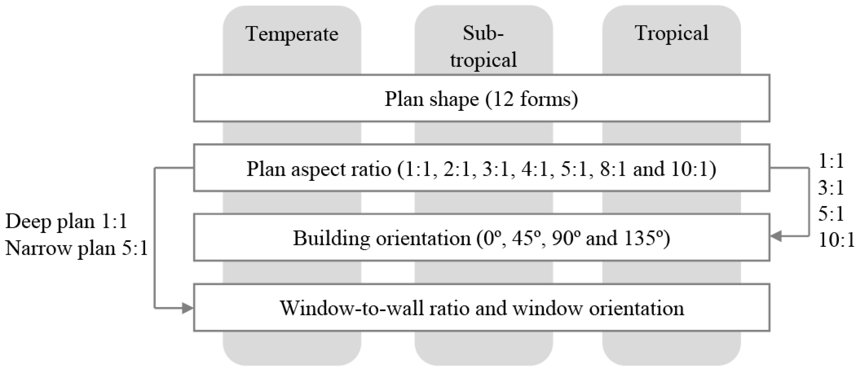
3. Methodology
3.1. Building Model
3.2. Sensitivity Test
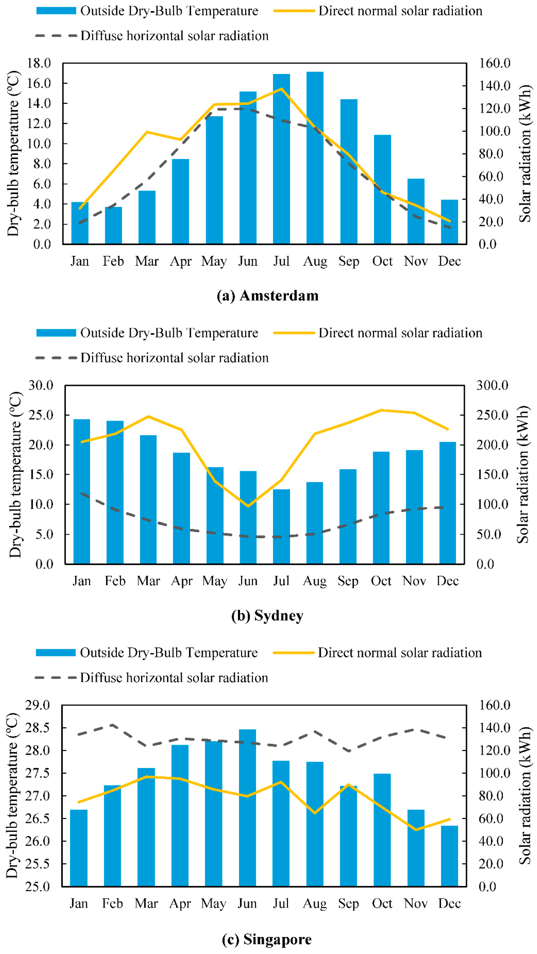
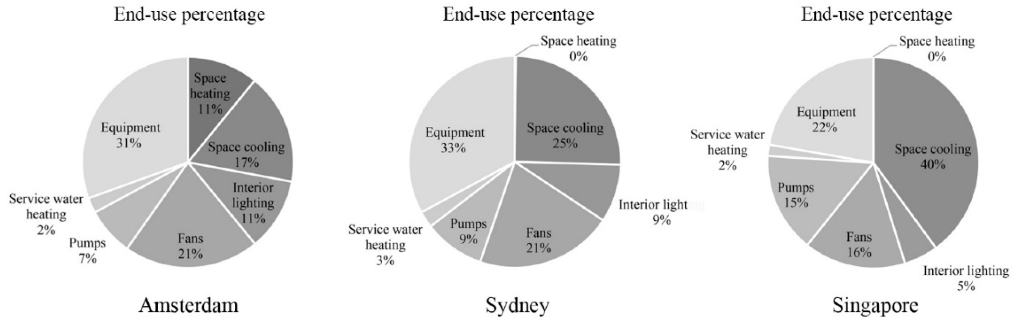
3.3. Location and Climate Type
4. Results and Discussion
4.1. Plan Shape and Building Energy Performance
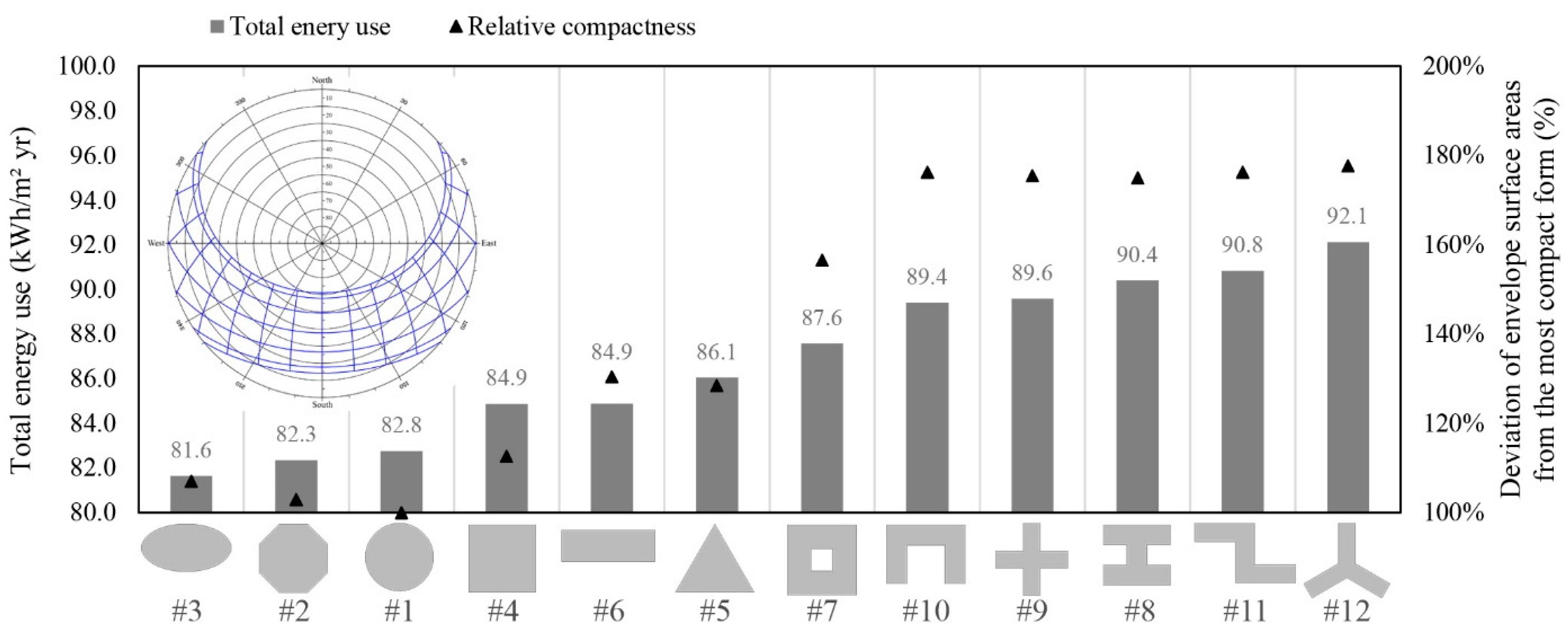
4.1.1. Temperate Climate
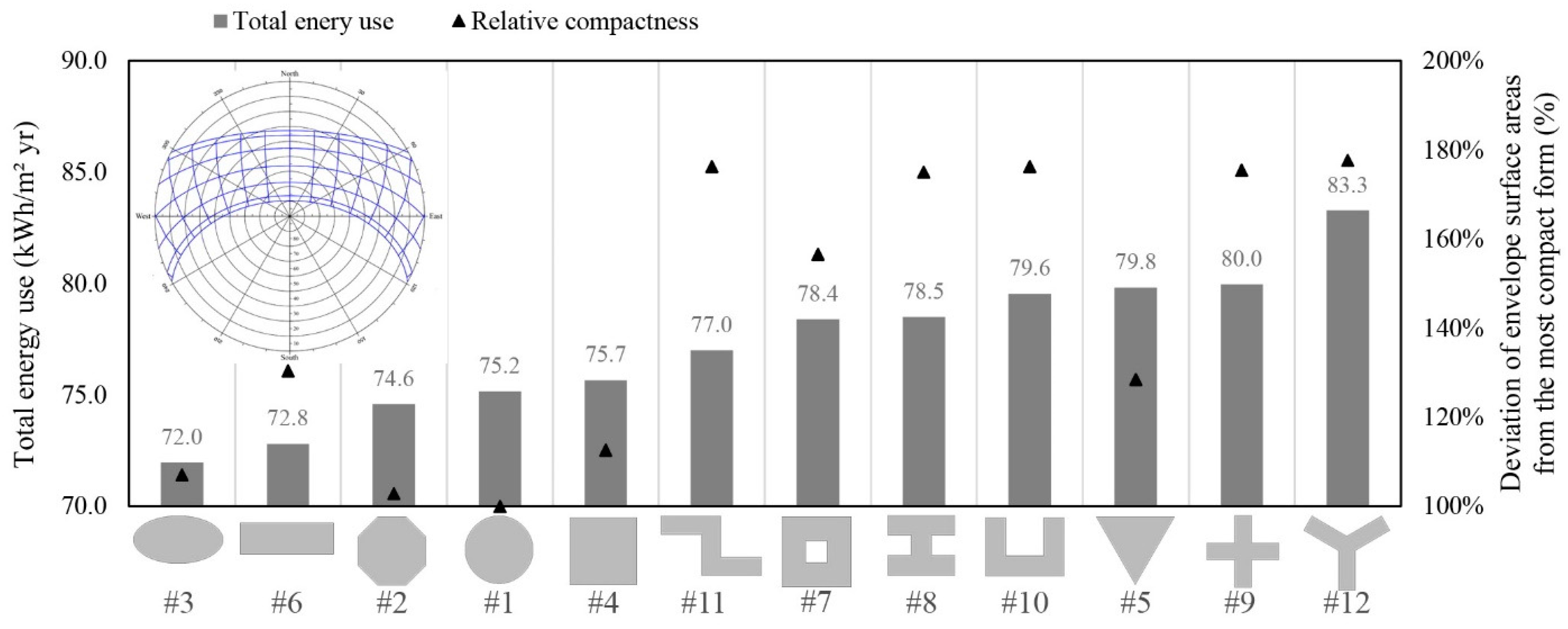
4.1.2. Sub-Tropical Climate
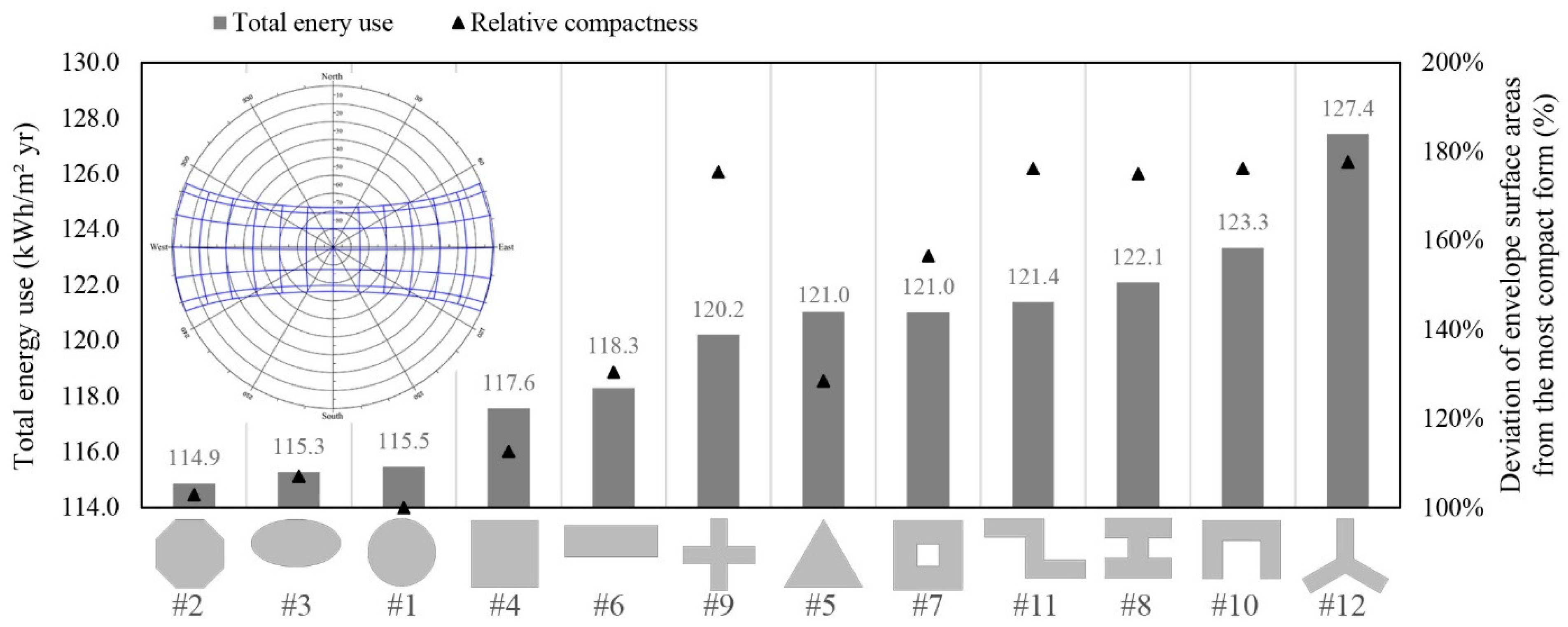
4.1.3. Tropical Climate
4.1.4. Suitability of Plan Shape for Architectural Design
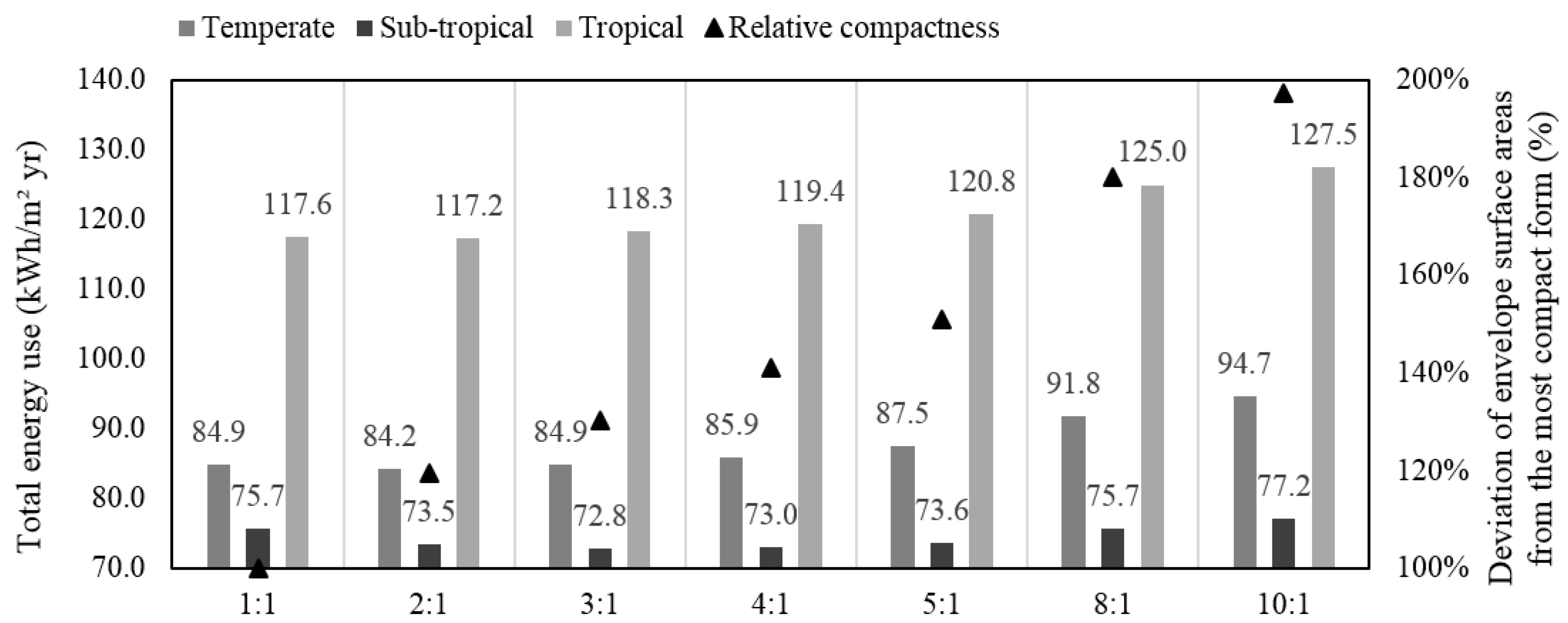
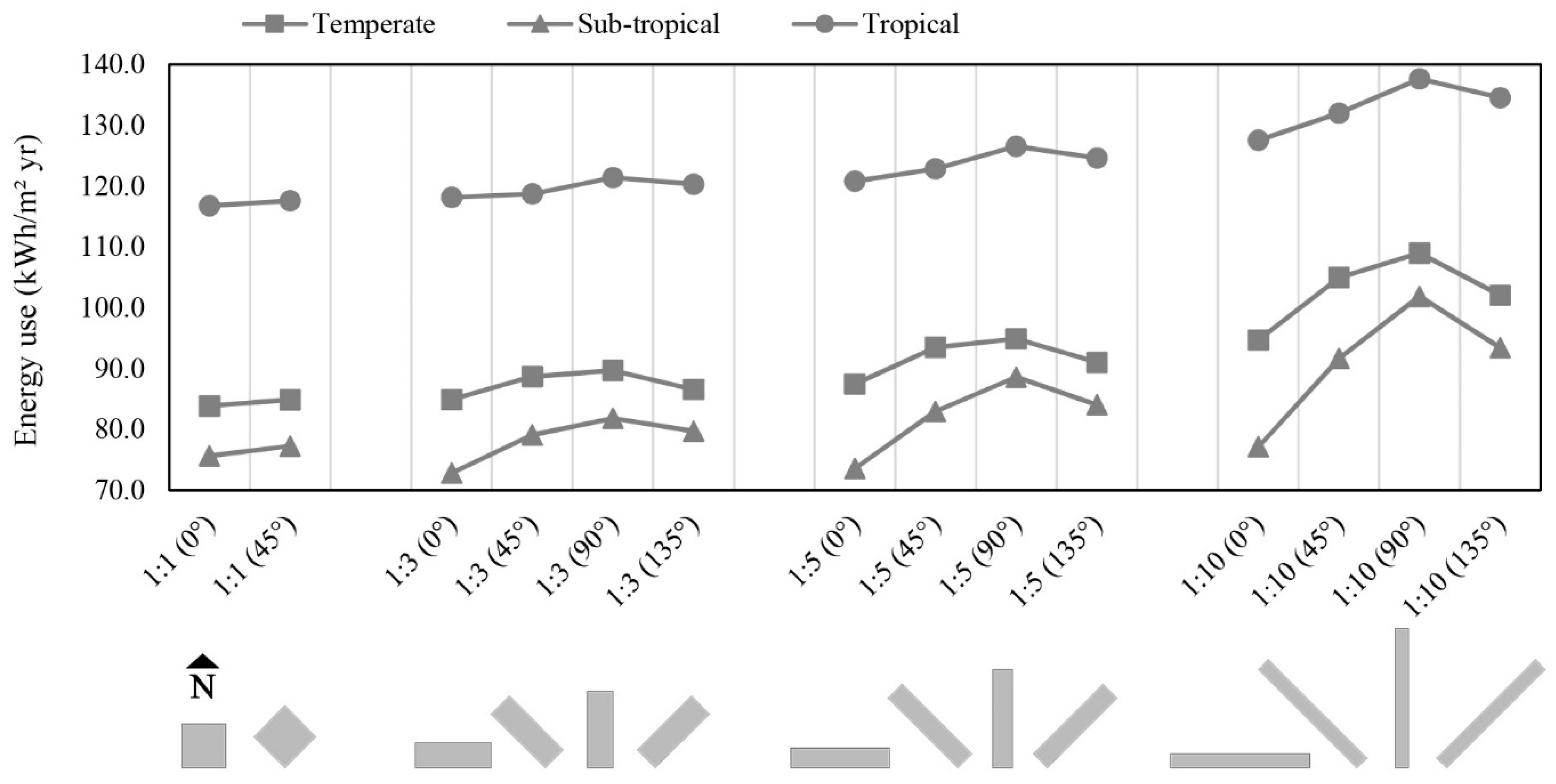
4.2. Plan Depth and Building Energy Performance
4.3. Plan Orientation and Building Energy Performance
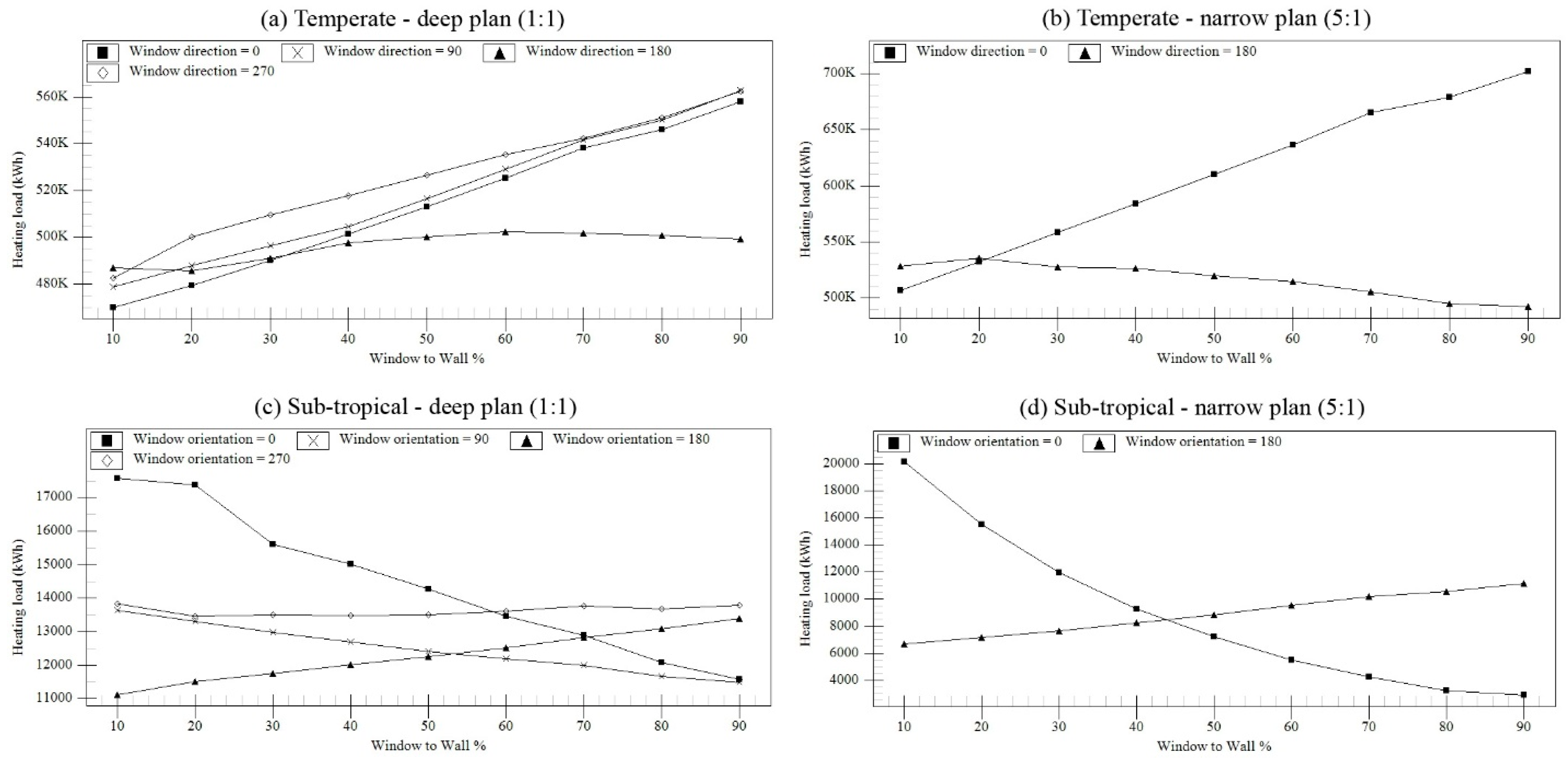
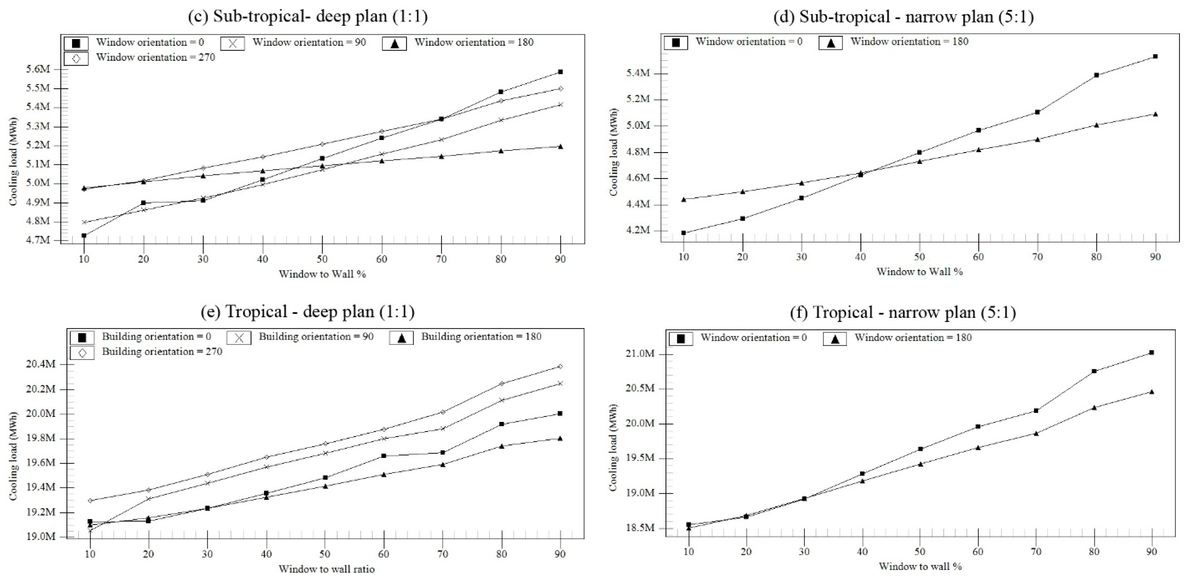
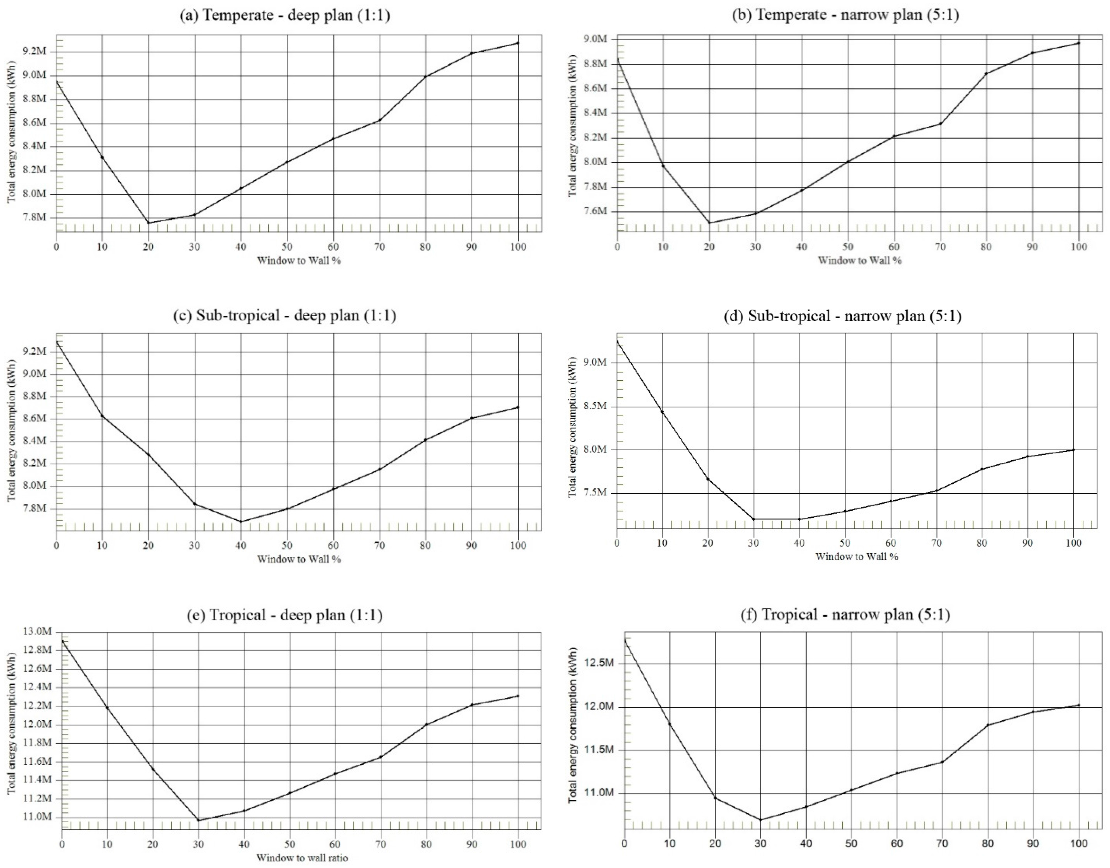
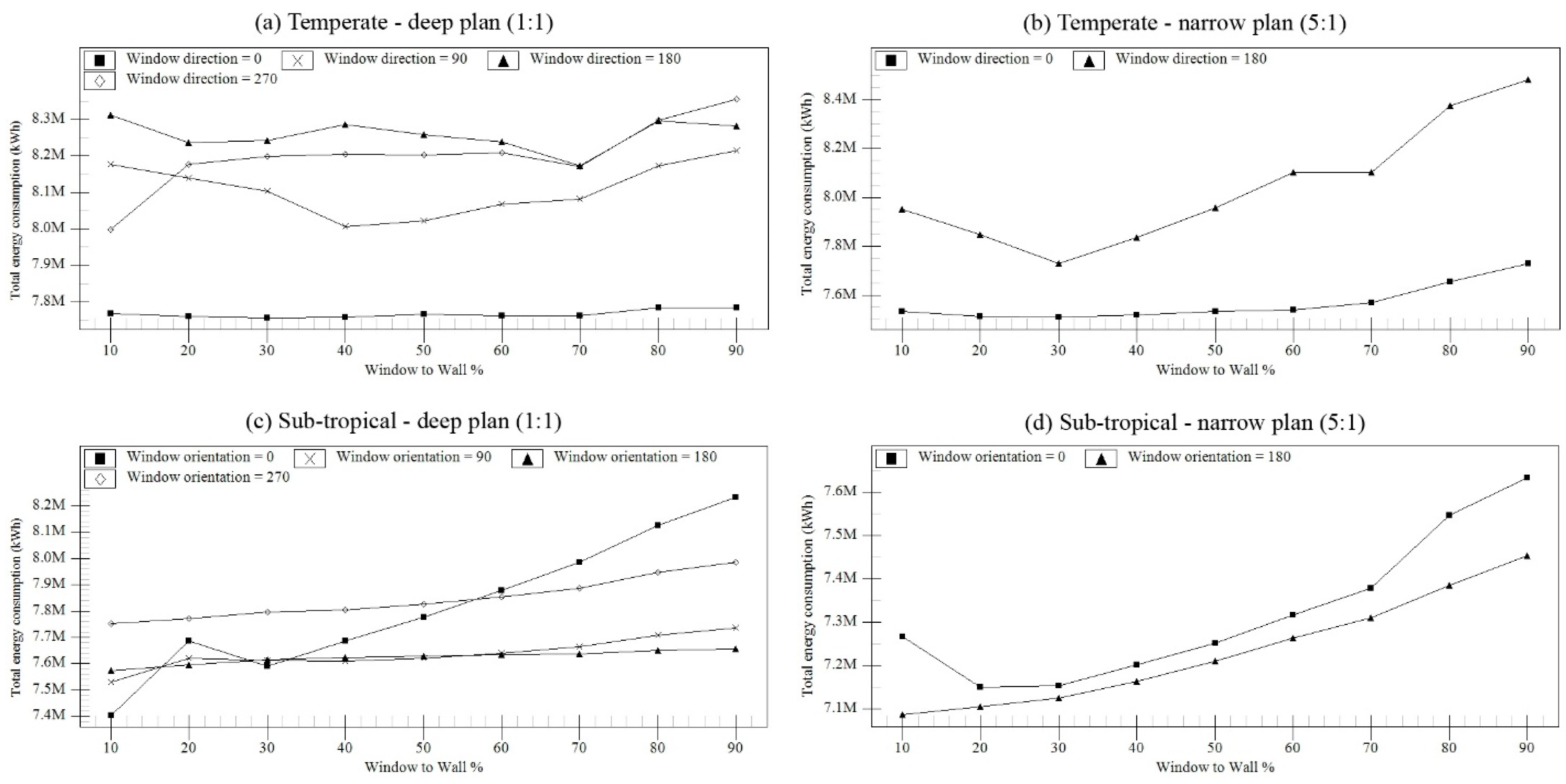
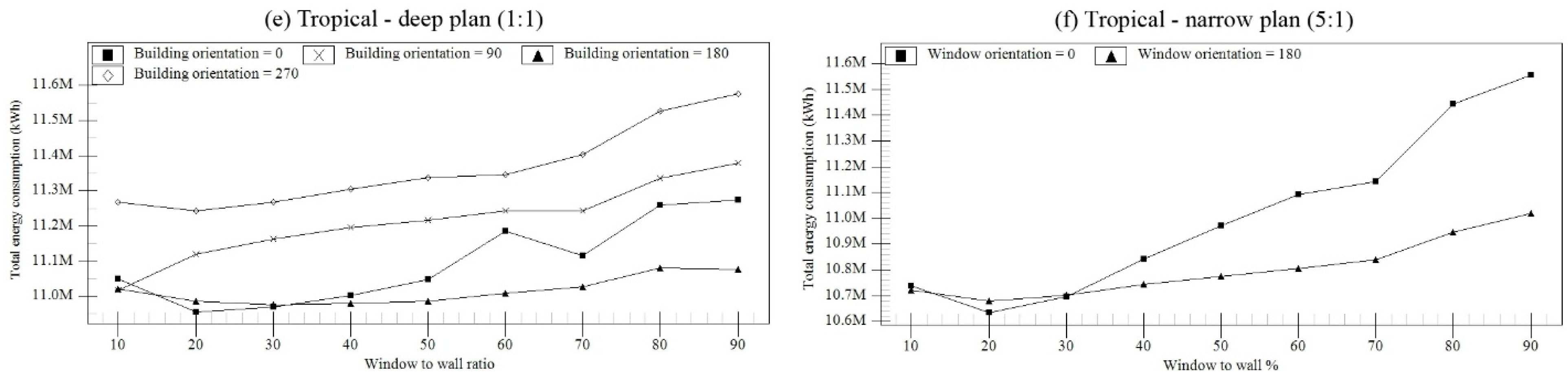
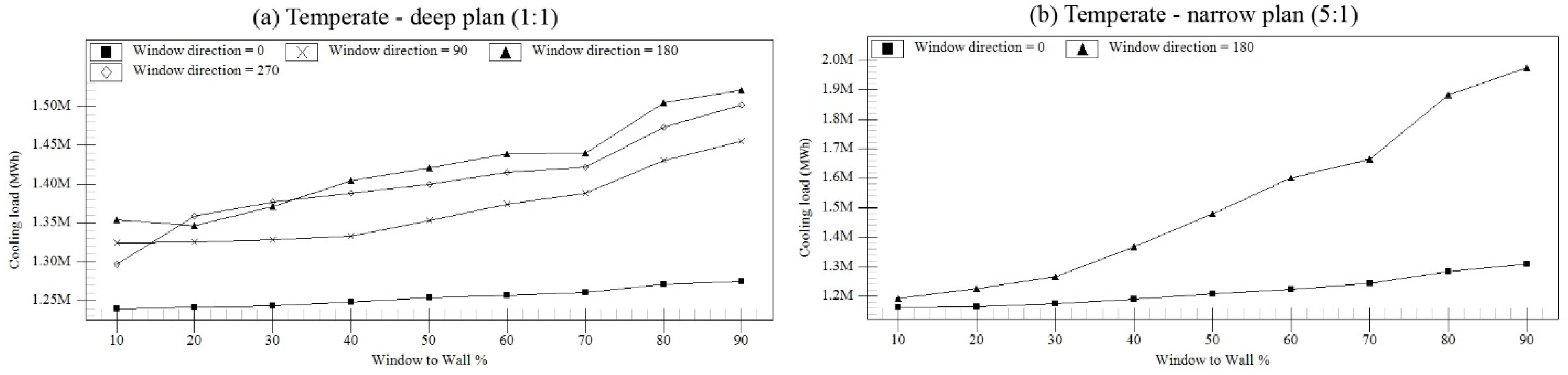
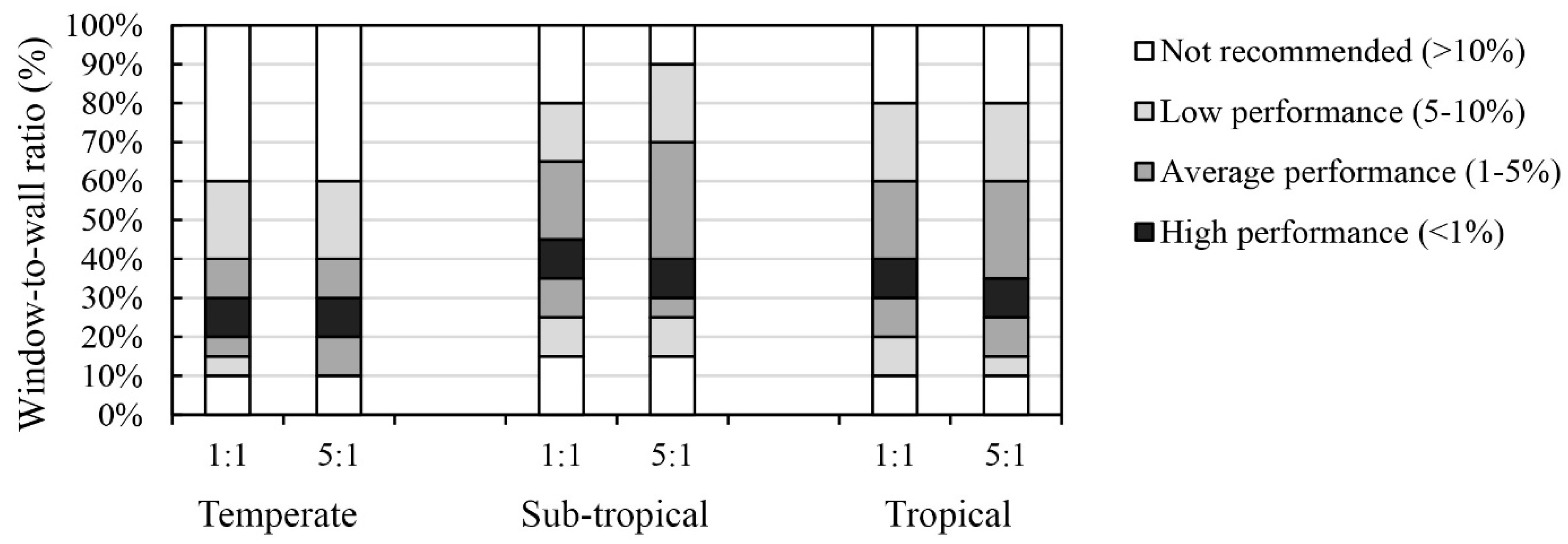
4.4. Window-to-Wall Ratio and Building Energy Performance
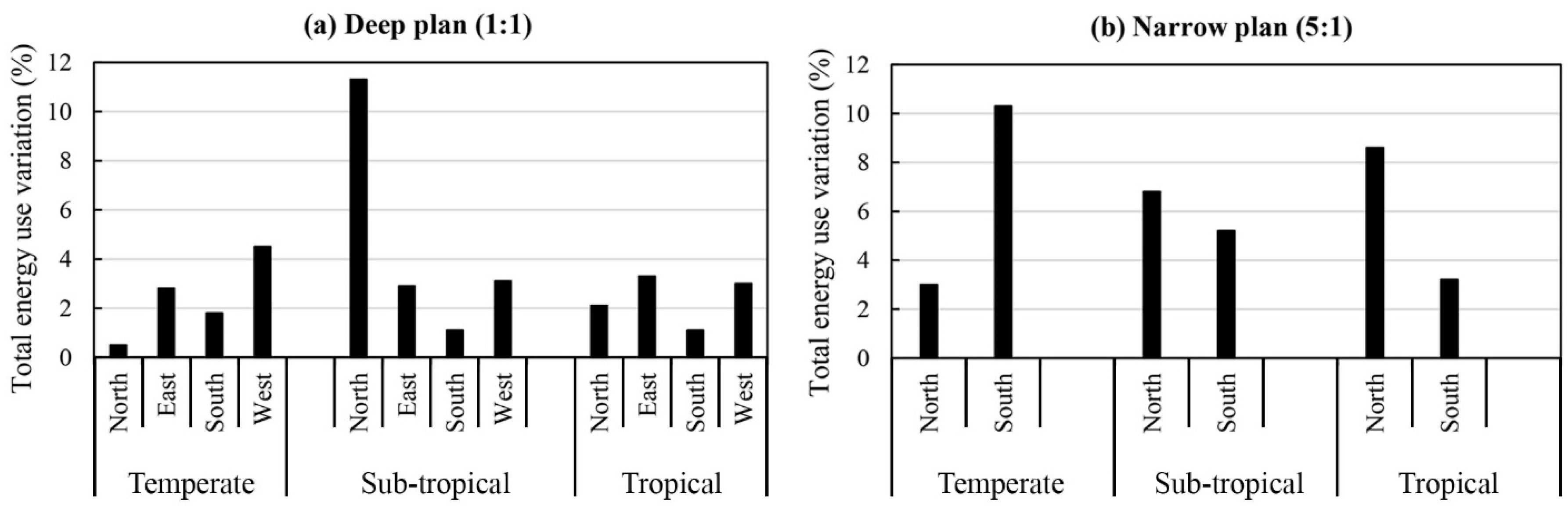
4.5. Window Orientation and Building Energy Performance
4.6. Research Limitations and Recommendations
5. Conclusions
- The effect of plan shape on building energy consumption is the highest in the sub-tropical climate (15.7%), and is lowest in the temperate climate (12.8%) and tropical climate (11.0%). The ellipse was found to be the ideal plan shape in all climates. It is the most efficient form in temperate and sub-tropical climates and the second efficient form in tropical climates after the octagon. Furthermore, the Y shape is the least efficient form in all climates.
- The effect of plan depth on total energy consumption is more dominant in the temperate climate (12.8%) than in the tropical (8.8%) and sub-tropical climate (6.0%). The optimal range of plan aspect ratio are 1:1 to 3:1 in Amsterdam, 3:1 to 4:1 in Sydney, and 1:1 to 3:1 in Singapore.
- In all climates, a rotation 0° from the north was found to be the ideal orientation for energy efficiency. In addition, a 90° rotation from the north is the least efficient orientation in all climates and for all plan aspect ratios (1:1 to 10:1) with an equiangular four-sided plan shape.
- Assuming that windows are equally distributed across building orientations, for a deep plan design, the optimal range of the window-to-wall ratio is 20–30% in the temperate climate, 35–45% in the sub-tropical climate, and 30–40% in the tropical climate. For a narrow plan design (with no glazing for the east- and west-facing walls), the optimal range is 5% lower, except for the temperate climate, which has the same values as for the deep plan design.
- The investigation also highlights the most sensitive orientations that potentially increase the total energy use (relative value) to a large extent for a wrong selection of WWR in different climates; those include the west-facing exposure in temperate climates (+4.5%), the north-facing exposure in sub-tropical climates (+11.3%), and the two facades facing east and west in tropical climates (up to 3.3%). Furthermore, the recommended WWR values are pointed out for different orientations and climates (see Table 9).
Acknowledgments
Author Contributions
Conflicts of Interest
Appendix A

| (a) Amsterdam | ||||||
| Plan Aspect Ratio | Breakdown of Annual Total Energy Demand | Annual Total Energy Demand | ||||
| Heating/Conditioned Area (kW h/m2) | Cooling/Conditioned Area (kW h/m2) | Lighting/Conditioned Area (kW h/m2) | Fan/Conditioned Area (kW h/m2) | Total/Conditioned Area (kW h/m2) | Percentile Difference (%) | |
| 1:1 | 15.2 | 23.5 | 17.5 | 28.7 | 84.9 | 0.8% |
| 2:1 ® | 15.3 | 23.6 | 16.7 | 28.6 | 84.2 | - |
| 3:1 | 15.5 | 24.2 | 15.8 | 29.4 | 84.9 | 0.8% |
| 4:1 | 15.6 | 24.9 | 15.0 | 30.4 | 85.9 | 2.1% |
| 5:1 | 15.9 | 25.8 | 14.4 | 31.4 | 87.5 | 3.9% |
| 8:1 | 16.7 | 27.8 | 13.0 | 34.3 | 91.8 | 9.0% |
| 10:1 | 17.2 | 29.0 | 12.4 | 36.0 | 94.7 | 12.4% |
| (b) Sydney | ||||||
| Plan Aspect Ratio | Breakdown of Annual Total Energy Demand | Annual Total Energy Demand | ||||
| Heating/conditioned Area (kW h/m2) | Cooling/Conditioned Area (kW h/m2) | Lighting/Conditioned Area (kW h/m2) | Fan/Conditioned Area (kW h/m2) | Total/Conditioned Area (kW h/m2) | Percentile Difference (%) | |
| 1:1 | 0.4 | 34.2 | 12.6 | 28.4 | 75.7 | 4.0% |
| 2:1 | 0.3 | 33.3 | 12.3 | 27.6 | 73.5 | 1.0% |
| 3:1 ® | 0.3 | 32.8 | 11.7 | 28.0 | 72.8 | - |
| 4:1 | 0.2 | 33.5 | 11.3 | 28.0 | 73.0 | 0.3% |
| 5:1 | 0.2 | 34.0 | 10.9 | 28.5 | 73.6 | 1.1% |
| 8:1 | 0.2 | 35.3 | 10.2 | 30.0 | 75.7 | 4.0% |
| 10:1 | 0.2 | 36.1 | 10.0 | 30.9 | 77.2 | 6.0% |
| (c) Singapore | ||||||
| Plan Aspect Ratio | Breakdown of Annual Total Energy Demand | Annual Total Energy Demand | ||||
| Heating/Conditioned Area (kW h/m2) | Cooling/Conditioned Area (kW h/m2) | Lighting/Conditioned Area (kW h/m2) | Fan/Conditioned Area (kW h/m2) | Total/Conditioned Area (kW h/m2) | Percentile Difference (%) | |
| 1:1 | 0.0 | 76.5 | 11.3 | 29.5 | 117.6 | 0.3% |
| 2:1 ® | 0.0 | 76.7 | 10.8 | 29.7 | 117.2 | - |
| 3:1 | 0.0 | 77.8 | 10.2 | 30.3 | 118.3 | 0.9% |
| 4:1 | 0.0 | 78.7 | 9.5 | 31.2 | 119.4 | 1.9% |
| 5:1 | 0.0 | 79.7 | 9.0 | 32.1 | 120.8 | 3.0% |
| 8:1 | 0.0 | 82.6 | 8.1 | 34.3 | 125.0 | 6.6% |
| 10:1 | 0.0 | 84.2 | 7.7 | 35.7 | 127.5 | 8.8% |
Appendix B
Appendix C
Appendix D

Appendix E

References
- Bragança, L.; Vieira, S.M.; Andrade, J.B. Early stage design decisions: The way to achieve sustainable buildings at lower costs. Sci. World J. 2014. Available online: http://www.hindawi.com/journals/tswj/2014/365364/abs/ (accessed on 22 December 2016.).
- Attia, S.; De Herde, A. Design decision tools for zero energy buildings. In Proceedings of the 27th Conference on Passive and Low Energy Architecture, Louvain-la-Neuve, Belgium, 13–15 July 2011; pp. 77–82. [Google Scholar]
- Athienitis, A.; Attia, S. Strategic design, optimization, and modelling issues of net-zero energy solar buildings. In Proceedings of the Eurosun 2010, Graz, Austria, 28 September–1 October 2010. [Google Scholar]
- Pessenlehner, W.; Mahdavi, A. Building morphology, transparence, and energy performance. In Proceedings of the Eighth International IBPSA Conference, Eindhoven, The Netherlands, 2003; pp. 1025–1032. [Google Scholar]
- Depecker, P.; Menezo, C.; Virgone, J.; Lepers, S. Design of buildings shape and energetic consumption. Build. Environ. 2001, 36, 627–635. [Google Scholar] [CrossRef]
- Ourghi, R.; Al-Anzi, A.; Krarti, M. A simplified analysis method to predict the impact of shape on annual energy use for office buildings. Energy Convers. Manag. 2007, 48, 300–305. [Google Scholar] [CrossRef]
- AlAnzi, A.; Seo, D.; Krarti, M. Impact of building shape on thermal performance of office buildings in kuwait. Energy Convers. Manag. 2009, 50, 822–828. [Google Scholar] [CrossRef]
- Choi, I.Y.; Cho, S.H.; Kim, J.T. Energy consumption characteristics of high-rise apartment buildings according to building shape and mixed-use development. Energy Build. 2012, 46, 123–131. [Google Scholar] [CrossRef]
- Susorova, I.; Tabibzadeh, M.; Rahman, A.; Clack, H.L.; Elnimeiri, M. The effect of geometry factors on fenestration energy performance and energy savings in office buildings. Energy Build. 2013, 57, 6–13. [Google Scholar] [CrossRef]
- Kämpf, J.H.; Robinson, D. Optimisation of building form for solar energy utilisation using constrained evolutionary algorithms. Energy Build. 2010, 42, 807–814. [Google Scholar] [CrossRef]
- Yi, Y.K.; Malkawi, A.M. Site-specific optimal energy form generation based on hierarchical geometry relation. Autom. Constr. 2012, 26, 77–91. [Google Scholar] [CrossRef]
- Wang, W.; Rivard, H.; Zmeureanu, R. An object-oriented framework for simulation-based green building design optimization with genetic algorithms. Adv. Eng. Inform. 2005, 19, 5–23. [Google Scholar] [CrossRef]
- Magnier, L.; Haghighat, F. Multiobjective optimization of building design using trnsys simulations, genetic algorithm, and artificial neural network. Build. Environ. 2010, 45, 739–746. [Google Scholar] [CrossRef]
- Yi, Y.K.; Malkawi, A.M. Optimizing building form for energy performance based on hierarchical geometry relation. Autom. Constr. 2009, 18, 825–833. [Google Scholar] [CrossRef]
- Malkawi, A.M. Developments in environmental performance simulation. Autom. Constr. 2004, 13, 437–445. [Google Scholar] [CrossRef]
- US Department of Energy. Weather Data. Available online: https://energyplus.net/weather (accessed on 20 September 2016).
- Wood, A.; Salib, R. Natural Ventilation in High-Rise Office Buildings, Ctbuh Technical Guides; Routledge: New York, NY, USA, 2013. [Google Scholar]
- Straube, J.F.; Burnett, E.F.P. Building Science for Building Enclosures; Building Science Press: Westford, MA, USA, 2005. [Google Scholar]
- Raji, B.; Tenpierik, M.J.; van den Dobbelsteen, A. A comparative study: Design strategies for energy-efficiency of high-rise office buildings. J. Green Build. 2016, 11, 134–158. [Google Scholar] [CrossRef]
- Van den Dobbelsteen, A.; Thijssen, S.; Colaleo, V.; Metz, T. Ecology of the building geometry-environmental performance of different building shapes. In Proceedings of the CIB World Building Congress 2007; CIB/CSIR. Cape Town, South Africa, 14–17 May 2007; pp. 178–188. [Google Scholar]
- Watts, S. Tall building economics. In The Tall Buildings Reference Book; Parker, D., Wood, A., Eds.; Routledge: New York, NY, USA, 2013; pp. 49–70. [Google Scholar]
- Wilkinson, C. Aesthetics, symbolism and status in the twenty-first century. In The Tall Buildings Reference Book; Parker, D., Wood, A., Eds.; Routledge: New York, NY, USA, 2013; pp. 33–40. [Google Scholar]
- Florides, G.A.; Tassou, S.A.; Kalogirou, S.A.; Wrobel, L.C. Measures used to lower building energy consumption and their cost effectiveness. Appl. Energy 2002, 73, 299–328. [Google Scholar] [CrossRef]
- Pacheco, R.; Ordóñez, J.; Martínez, G. Energy efficient design of building: A review. Renew. Sustain. Energy Rev. 2012, 16, 3559–3573. [Google Scholar] [CrossRef]
- Mingfang, T. Solar control for buildings. Build. Environ. 2002, 37, 659–664. [Google Scholar] [CrossRef]
- Abanda, F.H.; Byers, L. An investigation of the impact of building orientation on energy consumption in a domestic building using emerging bim (building information modelling). Energy 2016, 97, 517–527. [Google Scholar] [CrossRef]
- Kheiri, F. The relation of orientation and dimensional specifications of window with building energy consumption in four different climates of koppen classification. Researcher 2013, 5, 107–115. [Google Scholar]
- Goia, F.; Haase, M.; Perino, M. Optimizing the configuration of a façade module for office buildings by means of integrated thermal and lighting simulations in a total energy perspective. Appl. Energy 2013, 108, 515–527. [Google Scholar] [CrossRef]
- Wang, L.; Mathew, P.; Pang, X. Uncertainties in energy consumption introduced by building operations and weather for a medium-size office building. Energy Build. 2012, 53, 152–158. [Google Scholar] [CrossRef]


| Building Properties | |
| External wall insulation | U-Value: 0.35 W/m2-K |
| Roof insulation | U-Value: 0.35 W/m2-K |
| Glazing type A 1 | Dbl LoE (e2 = 0.1) Clr 6 mm/13 mm |
| U-Value | Arg |
| SHGC | 1.50 W/m2-K |
| Light transmission | 0.57 |
| 0.74 | |
| Glazing type B 2 | Dbl LoE Spec Sel Clr 6 mm/13 mm |
| U-Value | Arg |
| SHGC | 1.34 W/m2-K |
| Light transmission | 0.42 |
| 0.68 | |
| Window-to-wall ratio | 50% |
| Shading | Blinds (inside) with high-reflectivity slats |
| Shading control type | Glare |
| Maximum allowable glare index | 22 |
| Building Operation Details | |
| HVAC system type | Dual duct VAV |
| Heating | Gas-fired condensing boiler |
| Heating set point temperature | 20 °C |
| Cooling | DOE-2 centrifugal/5.50COP |
| Cooling set point temperature | 24 °C |
| Fan Power | 2 W/l-s |
| Fan total efficiency | 70% |
| Fresh air supply rate | 10 L/s-person |
| Infiltration | 0.5 ac/h |
| Lighting target illuminance | 400 lux |
| Type of lighting | Fluorescent |
| General lighting power density | 3.4 W/m2-100 lux |
| Office equipment gain | 11.77 W/m2 |
| Occupancy density | 0.11 people/m2 |
| Occupancy schedule | Weekdays: 7:00–19:00; weekends: closed |
| Building Parameter | Climate | Values | Max. Variation (kW h/m2) | ||
| Glazing type | Temperate | A *,max, D min | 4.1 | ||
| Sub-tropical | A max, B *,min, D | 12.6 | |||
| Tropical | A, B *,min, C max, D | 21.8 | |||
| Shading system | Temperate | E min, F max, G * | 11.3 | ||
| Sub-tropical | E, F max, G *, H min | 6.7 | |||
| Tropical | E, F max, G *, H min | 18.1 | |||
| Glazing Description | U-Value | SHGC 1 | TSOL 2 | TVIS 3 | |
| Type A. Dbl LoE (e2 = 0.1) Clr 6 mm/13 mm Arg | 1.50 | 0.57 | 0.47 | 0.74 | |
| Type B. Dbl LoE Spec Sel Clr 6 mm/13 mm Arg | 1.34 | 0.42 | 0.34 | 0.68 | |
| Type C. Dbl Ref-A-H Clr 6 mm/13 mm Arg | 2.26 | 0.22 | 0.13 | 0.18 | |
| Type D. Trp LoE (e2 = e5 = 0.1) Clr 3 mm/13 mm Arg | 0.79 | 0.47 | 0.36 | 0.66 | |
| Shading Description | Control Type | ||||
| Type E. Blinds outside | Solar: (120 W/m2) | ||||
| Type F. Blinds inside | Solar: (120 W/m2) | ||||
| Type G. Blinds inside | Glare: (glare index: 22) | ||||
| Type H. Integrated shading system: overhang 0.5 m + blinds outside | Solar: (120 W/m2) | ||||
| City | Climate Type | HDD | CDD |
|---|---|---|---|
| Amsterdam 1 | Temperate | 2759 | 149 |
| Sydney 2 | Sub-tropical | 594 | 896 |
| Singapore 3 | Tropical | 0 | 3657 |
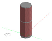
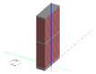
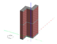
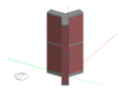
| Plan Shape | Shape 1 | Shape 2 | Shape 3 | Shape 4 | Shape 5 | Shape 6 |
 |  |  |  |  |  | |
| Share of each façade from the total glazing area (%) |  |  |  |  |  |  |
| Floor plate dimensions | 43.7 m2 | 42.6 m between facades | major axis: 60 minor axis: 32 | 38.7 m between facades | 51.1 m altitude | 67.1 × 22.4 Length × width |
| Relative compactness | 100% | 103% | 107% | 113% | 128% | 130% |
| Plan depth indicator | 47% | 48% | 52% | 52% | 58% | 62% |
| Plan Shape | Shape 7 | Shape 8 | Shape 9 | Shape 10 | Shape 11 | Shape 12 |
 |  |  |  |  |  | |
| Share of each façade from the total glazing area (%) |  |  |  |  |  |  |
| Floor plate dimensions | 14.0 m from void | 46.6 × 42.0 overall length × width 14.0 m between facades | 60.6 × 60.6 overall length × width 14.0 m between facades | 54.4 × 40.4 overall length × width 14.0 m between facades | 76.1 × 45.1 overall length × width 14.0 m between facades | 33.7 m wing lenght 14.0 m between facades |
| Relative compactness | 157% | 175% | 175% | 176% | 176% | 178% |
| Plan depth indicator | 86% | 87% | 87% | 87% | 87% | 87% |
| Plan Shape | Breakdown of Annual Total Energy Demand | Annual Total Energy Demand | ||||
|---|---|---|---|---|---|---|
| Heating/Conditioned Area (kW h/m2) | Cooling/Conditioned Area (kW h/m2) | Lighting/Conditioned Area (kW h/m2) | Fan/Conditioned Area (kW h/m2) | Total/Conditioned Area (kW h/m2) | Percentile Difference (%) | |
| Shape 1 | 15.1 | 22.5 | 17.9 | 27.3 | 82.8 | 1.4% |
| Shape 2 | 15.2 | 22.6 | 17.1 | 27.4 | 82.3 | 0.9% |
| Shape 3 ® | 14.9 | 22.5 | 17.2 | 27.0 | 81.6 | - |
| Shape 4 | 15.2 | 23.5 | 17.5 | 28.7 | 84.9 | 4.0% |
| Shape 5 | 15.6 | 24.3 | 16.4 | 29.7 | 86.1 | 5.4% |
| Shape 6 | 15.5 | 24.2 | 15.8 | 29.4 | 84.9 | 4.0% |
| Shape 7 | 18.5 | 24.1 | 14.6 | 30.5 | 87.6 | 7.3% |
| Shape 8 | 19.2 | 24.4 | 15.6 | 31.2 | 90.4 | 10.7% |
| Shape 9 | 19.7 | 24.6 | 13.9 | 31.4 | 89.6 | 9.7% |
| Shape 10 | 19.5 | 24.3 | 14.6 | 31.0 | 89.4 | 9.5% |
| Shape 11 | 18.5 | 25.8 | 14.0 | 32.6 | 90.8 | 11.2% |
| Shape 12 | 18.9 | 26.0 | 14.4 | 32.9 | 92.1 | 12.8% |
| Plan Shape | Breakdown of Annual Total Energy Demand | Annual Total Energy Demand | ||||
|---|---|---|---|---|---|---|
| Heating/Conditioned Area (kW h/m2) | Cooling/Conditioned Area (kW h/m2) | Lighting/Conditioned Area (kW h/m2) | Fan/Conditioned Area (kW h/m2) | Total/Conditioned Area (kW h/m2) | Percentile Difference (%) | |
| Shape 1 | 0.4 | 33.5 | 13.6 | 27.6 | 75.2 | 4.5% |
| Shape 2 | 0.4 | 33.6 | 12.8 | 27.7 | 74.6 | 3.7% |
| Shape 3 ® | 0.3 | 32.3 | 12.7 | 26.5 | 72.0 | - |
| Shape 4 | 0.4 | 34.2 | 12.6 | 28.4 | 75.7 | 5.1% |
| Shape 5 | 0.4 | 35.8 | 13.5 | 30.1 | 79.8 | 10.9% |
| Shape 6 | 0.3 | 32.8 | 11.7 | 28.0 | 72.8 | 1.2% |
| Shape 7 | 0.5 | 36.0 | 11.8 | 30.1 | 78.4 | 9.0% |
| Shape 8 | 0.5 | 36.3 | 11.3 | 30.5 | 78.5 | 9.1% |
| Shape 9 | 0.6 | 36.9 | 11.4 | 31.1 | 80.0 | 11.1% |
| Shape 10 | 0.5 | 37.1 | 10.7 | 31.3 | 79.6 | 10.5% |
| Shape 11 | 0.4 | 35.9 | 10.6 | 30.2 | 77.0 | 7.0% |
| Shape 12 | 0.4 | 39.1 | 10.3 | 33.5 | 83.3 | 15.7% |
| Plan Shape | Breakdown of Annual Total Energy Demand | Annual Total Energy Demand | ||||
|---|---|---|---|---|---|---|
| Heating/Conditioned Area (kW h/m2) | Cooling/Conditioned Area (kW h/m2) | Lighting/Conditioned Area (kW h/m2) | Fan/Conditioned Area (kW h/m2) | Total/Conditioned Area (kW h/m2) | Percentile Difference (%) | |
| Shape 1 | 0.0 | 75.4 | 11.7 | 28.4 | 115.5 | 0.5% |
| Shape 2 ® | 0.0 | 75.5 | 10.8 | 28.6 | 114.9 | - |
| Shape 3 | 0.0 | 75.5 | 11.3 | 28.4 | 115.3 | 0.4% |
| Shape 4 | 0.0 | 76.7 | 11.3 | 29.5 | 117.6 | 2.4% |
| Shape 5 | 0.0 | 79.0 | 10.4 | 31.6 | 121.0 | 5.4% |
| Shape 6 | 0.0 | 77.8 | 10.2 | 30.3 | 118.3 | 3.0% |
| Shape 7 | 0.0 | 79.0 | 10.6 | 31.4 | 121.0 | 5.4% |
| Shape 8 | 0.0 | 80.1 | 9.7 | 32.3 | 122.1 | 6.3% |
| Shape 9 | 0.0 | 79.6 | 8.7 | 31.9 | 120.2 | 4.7% |
| Shape 10 | 0.0 | 81.0 | 9.2 | 33.2 | 123.3 | 7.4% |
| Shape 11 | 0.0 | 80.5 | 8.7 | 32.2 | 121.4 | 5.7% |
| Shape 12 | 0.0 | 82.9 | 9.8 | 34.8 | 127.4 | 11.0% |
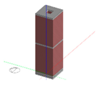
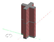
| Plan Aspect Ratio | 1:1 | 2:1 | 3:1 | 4:1 | 5:1 | 8:1 | 10:1 |
|---|---|---|---|---|---|---|---|
| Building shape |  |  |  |  |  |  |  |
| Share of each façade from the total glazing area (%) |  |  |  |  |  |  |  |
| Floor plate dimensions length × width | 38.7 × 38.7 m | 54.8 × 27.4 m | 67.1 × 22.4 m | 77.5 × 19.4 m | 86.6 × 17.3 m | 109.5 × 13.7 m | 122.5 × 12.2 m |
| Relative compactness | 100% | 120% | 130% | 140% | 150% | 180% | 197% |
| Plan depth indicator | 52% | 56% | 62% | 68% | 74% | 89% | 98% |
| Climate Type/Plan Aspect Ratio | Temperate | Sub-Tropical | Tropical | ||||
|---|---|---|---|---|---|---|---|
| 1:1 | 5:1 | 1:1 | 5:1 | 1:1 | 5:1 | ||
| Recommended WWR value (%) | North | 10–90 | 10–70 | 10–15 | 15–40 | 10–50 | 10–35 |
| East | 35–60 | No glazing | 10–20 | No glazing | 10–20 | No glazing | |
| South | 65–75 | 25–35 | 10–70 | 10–40 | 10–80 | 10–55 | |
| West | 10–15 | No glazing | 10–20 | No glazing | 10–20 | No glazing | |
| Temperate | Sub-Tropical | Tropical | ||||||||||||||||||||||
| Plan shape | A | B | C | D | A | B | C | D | A | B | C | D | ||||||||||||
| <1% | Ellipse | + | + | Ellipse | + | + | Octagon | + | + | |||||||||||||||
| Octagon | + | + | Ellipse | + | + | |||||||||||||||||||
| Circle | + | + | ||||||||||||||||||||||
| 1–5% | Circle | + | + | Rectangle | + | Square | + | + | ||||||||||||||||
| Square | + | + | Octagon | + | + | Rectangle | + | |||||||||||||||||
| Rectangle | + | Circle | + | + | + shape | + | ||||||||||||||||||
| 5–10% | Triangle | Square | + | + | Triangle | |||||||||||||||||||
| Atrium | + | Z shape | + | Courtyard | + | |||||||||||||||||||
| U shape | + | Courtyard | + | Z shape | + | |||||||||||||||||||
| + shape | + | H shape | + | H shape | + | |||||||||||||||||||
| U shape | + | |||||||||||||||||||||||
| >10% | H shape | + | U shape | + | Y shape | + | ||||||||||||||||||
| Z shape | + | Triangle | ||||||||||||||||||||||
| Y shape | + | + shape | + | |||||||||||||||||||||
| Y shape | + | |||||||||||||||||||||||
| MD (%) | 12.8 | 15.7 | 11.0 | |||||||||||||||||||||
| Plan aspect ratio | ||||||||||||||||||||||||
| <1% | 1:1, 2:1, 3:1 | 3:1, 4:1 | 1:1, 2:1, 3:1 | |||||||||||||||||||||
| 1–5% | 4:1, 5:1 | 1:1, 2:1, 5:1, 8:1 | 4:1, 5:1 | |||||||||||||||||||||
| 5–10% | 8:1 | 10:1 | 8:1, 10:1 | |||||||||||||||||||||
| >10% | 10:1 | --- | --- | |||||||||||||||||||||
| MD (%) | 12.4 | 6.0 | 8.8 | |||||||||||||||||||||
| Plan orientation | ||||||||||||||||||||||||
| 1:1 | 3:1 | 5:1 | 10:1 | 1:1 | 3:1 | 5:1 | 10:1 | 1:1 | 3:1 | 5:1 | 10:1 | |||||||||||||
| <1% | 0° | 0° | 0° | 0° | 0° | 0° | 0° | 0° | 0° 45° | 0° 45° | 0° | 0° | ||||||||||||
| 1–5% | 45° | 135° 45° | 135° | 45° | --- | --- | --- | --- | 135° 45° | 45° 135° 90° | 45° | |||||||||||||
| 5–10% | --- | 90° | 45° 90° | 135° | --- | 45° 135° | --- | --- | --- | --- | --- | 135° 90° | ||||||||||||
| >10% | --- | --- | --- | 45° 90° | --- | 90° | 45° 135° 90° | 45° 135° 90° | --- | --- | --- | --- | ||||||||||||
| MD (%) | 1.2 | 5.6 | 8.4 | 15.1 | 2.1 | 12.3 | 20.4 | 32.0 | 0.7 | 2.8 | 4.7 | 7.9 | ||||||||||||
| WWR (%): deep plan (1:1) | ||||||||||||||||||||||||
| N | E | S | W | N | E | S | W | N | E | S | W | |||||||||||||
| <1% | 10–90 | 35–60 | 65–75 | 10–15 | 10–15 | 10–20 | 10–70 | 10–20 | 10–50 | 10–20 | 10–80 | 10–20 | ||||||||||||
| 1–5% | --- | 10–35 60–90 | 10–65 75–90 | 15–90 | 15–50 | 20–90 | 70–90 | 20–90 | 50–90 | 20–90 | 80–90 | 20–90 | ||||||||||||
| 5–10% | --- | --- | --- | --- | 50–80 | --- | --- | --- | --- | --- | --- | --- | ||||||||||||
| >10% | --- | --- | --- | --- | 80–90 | --- | --- | --- | --- | --- | --- | --- | ||||||||||||
| MD (%) | 0.5 | 2.8 | 1.8 | 4.5 | 11.3 | 2.9 | 1.1 | 3.1 | 2.9 | 3.3 | 1.1 | 3.0 | ||||||||||||
| WWR (%): narrow plan (5:1) | ||||||||||||||||||||||||
| N | E | S | W | N | E | S | W | N | E | S | W | |||||||||||||
| <1% | 10–70 | --- | 25–35 | --- | 15–40 | --- | 10–40 | --- | 10–35 | --- | 10–55 | --- | ||||||||||||
| 1–5% | 70–90 | --- | 10–25 35–55 | --- | 10–15 40–75 | --- | 40–90 | --- | 35–70 | --- | 55–90 | --- | ||||||||||||
| 5–10% | --- | --- | 55–85 | --- | 75–90 | --- | --- | --- | 70–90 | --- | --- | --- | ||||||||||||
| >10% | --- | --- | 85–90 | --- | --- | --- | --- | --- | --- | --- | --- | --- | ||||||||||||
| MD (%) | 3.0 | --- | 10.3 | --- | 6.8 | --- | 5.2 | --- | 8.6 | --- | 3.2 | --- | ||||||||||||
 <1% (remarkable energy saving);
  1–5% (average energy saving);
  5–10% (low energy saving);
  >10% (not recommended). A: High space efficiency; B: Aerodynamic form; C: Narrow plan (NV & daylight access); D: Less material use for external envelope; MD: Maximum deviation; N: North orientation; E: East orientation; S: South orientation; W: West orientation.
© 2017 by the authors. Licensee MDPI, Basel, Switzerland. This article is an open access article distributed under the terms and conditions of the Creative Commons Attribution (CC BY) license (http://creativecommons.org/licenses/by/4.0/).
Share and Cite
Raji, B.; Tenpierik, M.J.; Van den Dobbelsteen, A. Early-Stage Design Considerations for the Energy-Efficiency of High-Rise Office Buildings. Sustainability 2017, 9, 623. https://doi.org/10.3390/su9040623
Raji B, Tenpierik MJ, Van den Dobbelsteen A. Early-Stage Design Considerations for the Energy-Efficiency of High-Rise Office Buildings. Sustainability. 2017; 9(4):623. https://doi.org/10.3390/su9040623
Chicago/Turabian StyleRaji, Babak, Martin J. Tenpierik, and Andy Van den Dobbelsteen. 2017. "Early-Stage Design Considerations for the Energy-Efficiency of High-Rise Office Buildings" Sustainability 9, no. 4: 623. https://doi.org/10.3390/su9040623
APA StyleRaji, B., Tenpierik, M. J., & Van den Dobbelsteen, A. (2017). Early-Stage Design Considerations for the Energy-Efficiency of High-Rise Office Buildings. Sustainability, 9(4), 623. https://doi.org/10.3390/su9040623