
Development and Evaluation of Applicable Optimal Terminal Box Control Algorithms for Energy Management Control Systems


Abstract
:1. Introduction
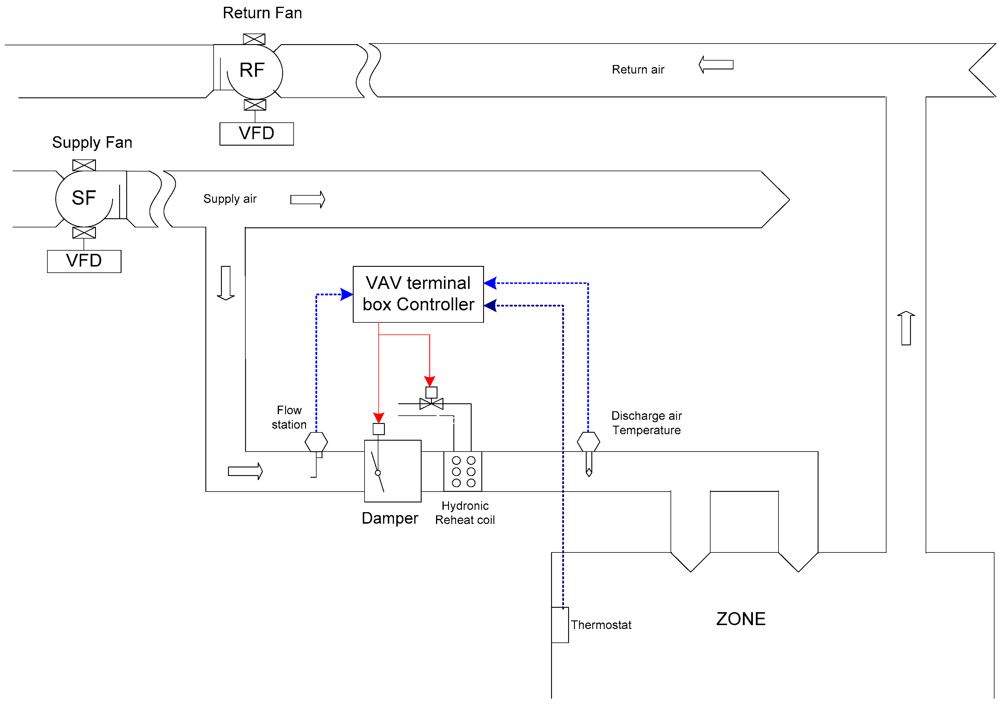
2. VAV Terminal Box Modeling
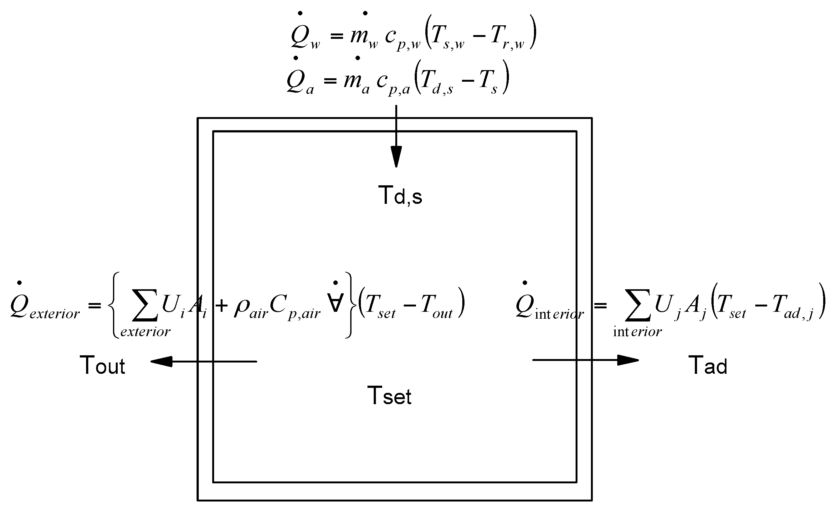
2.1. Zone Model
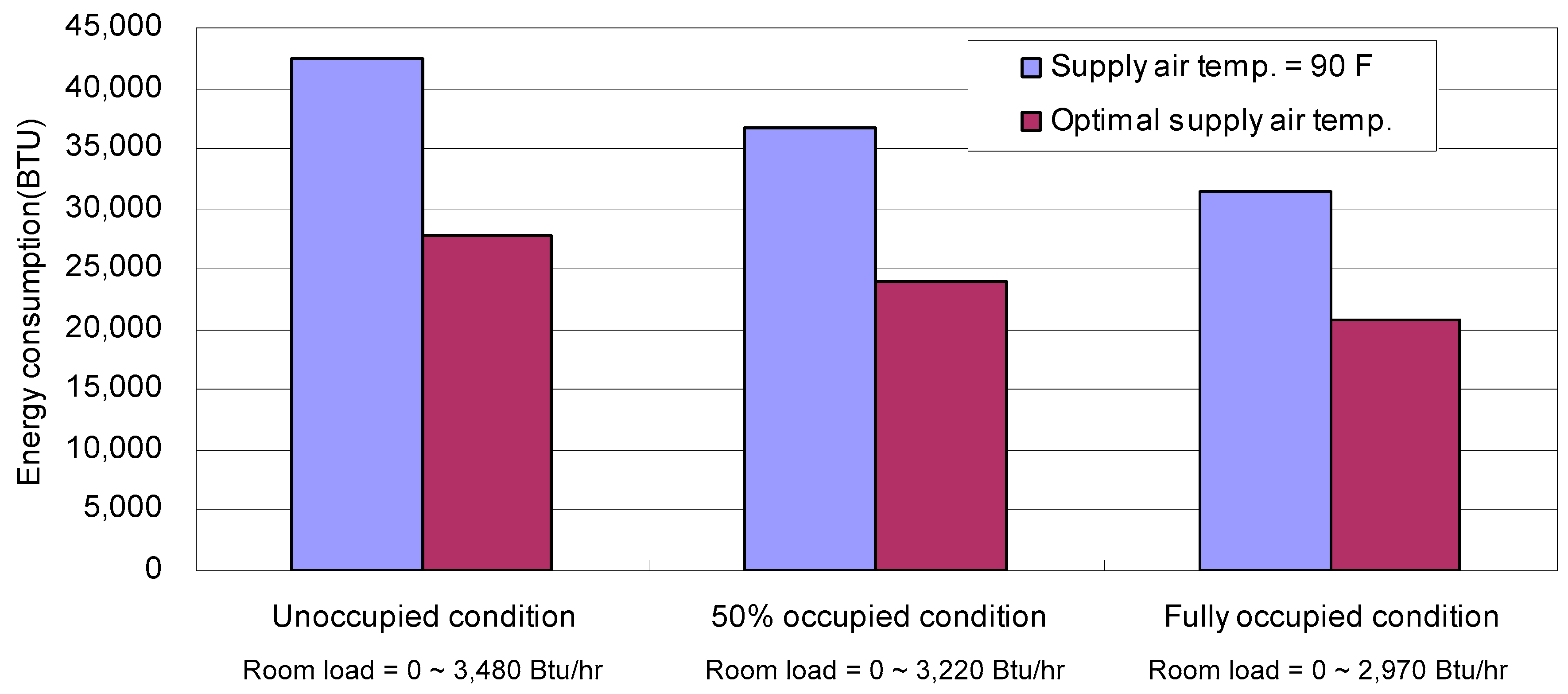
2.2. Reheating Coil Model
2.3. Damper and Valve Model
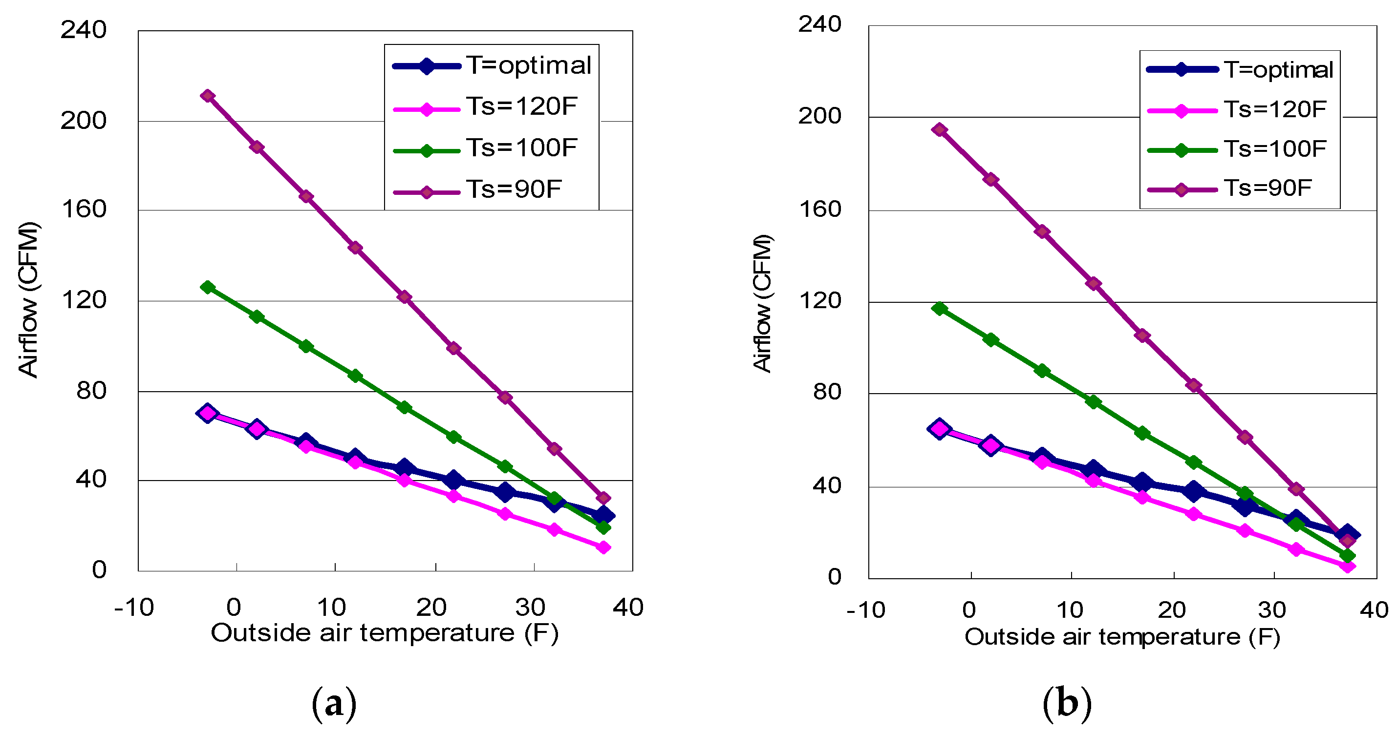
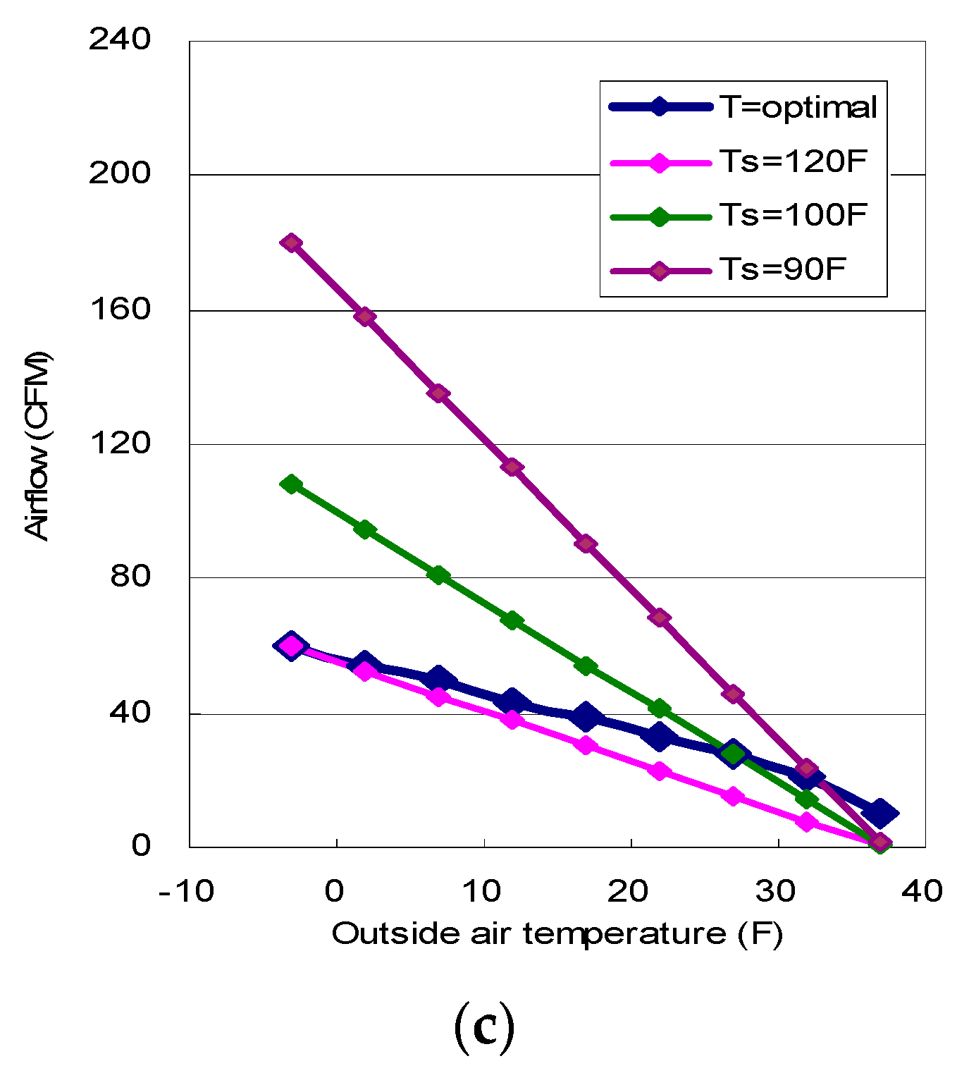
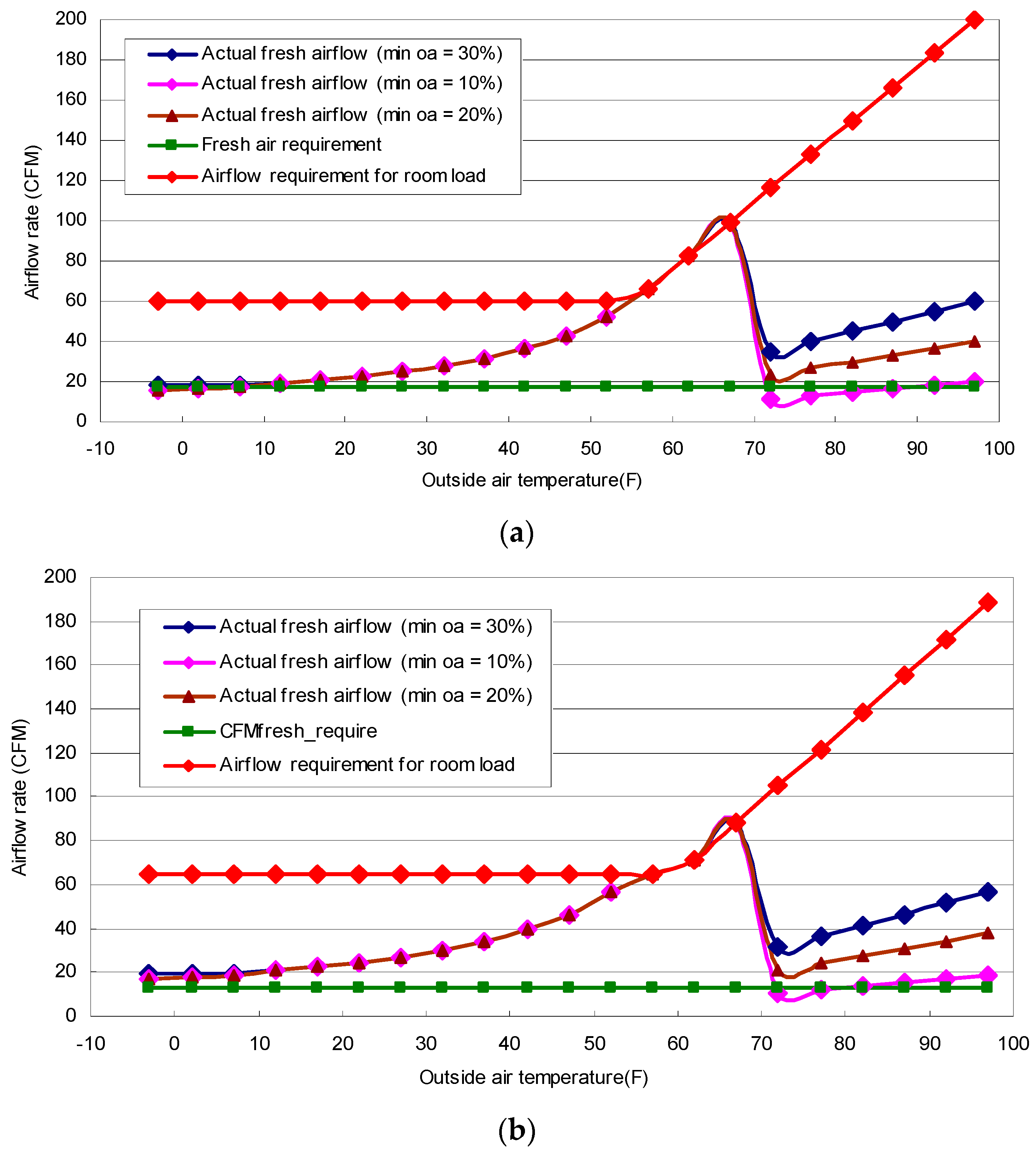
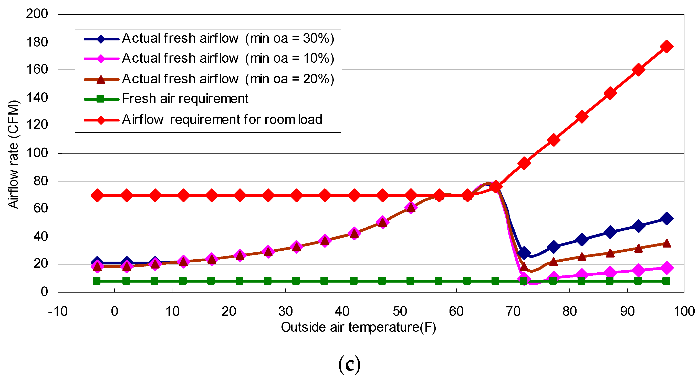
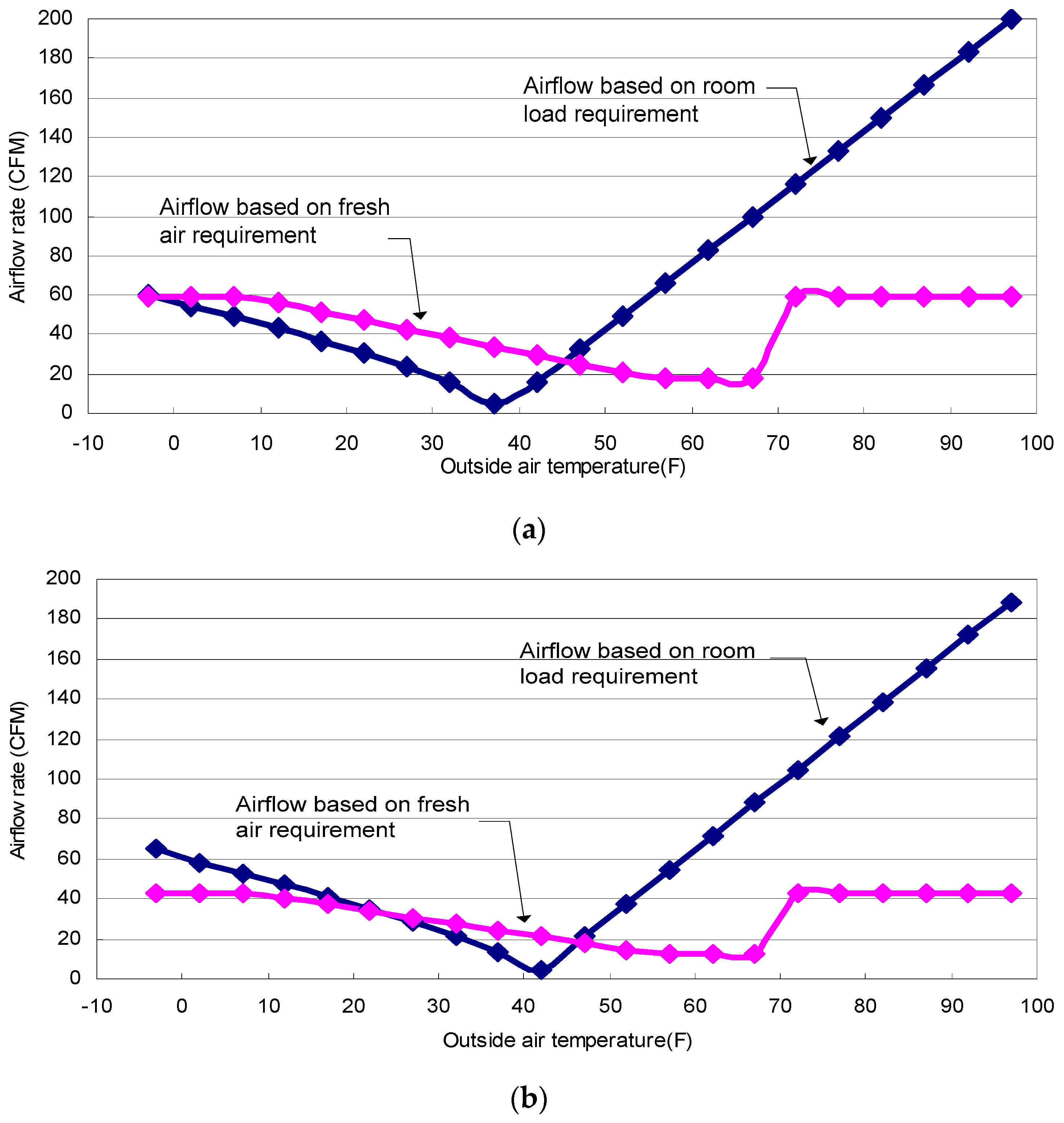
3. Optimal Minimum Air Flow
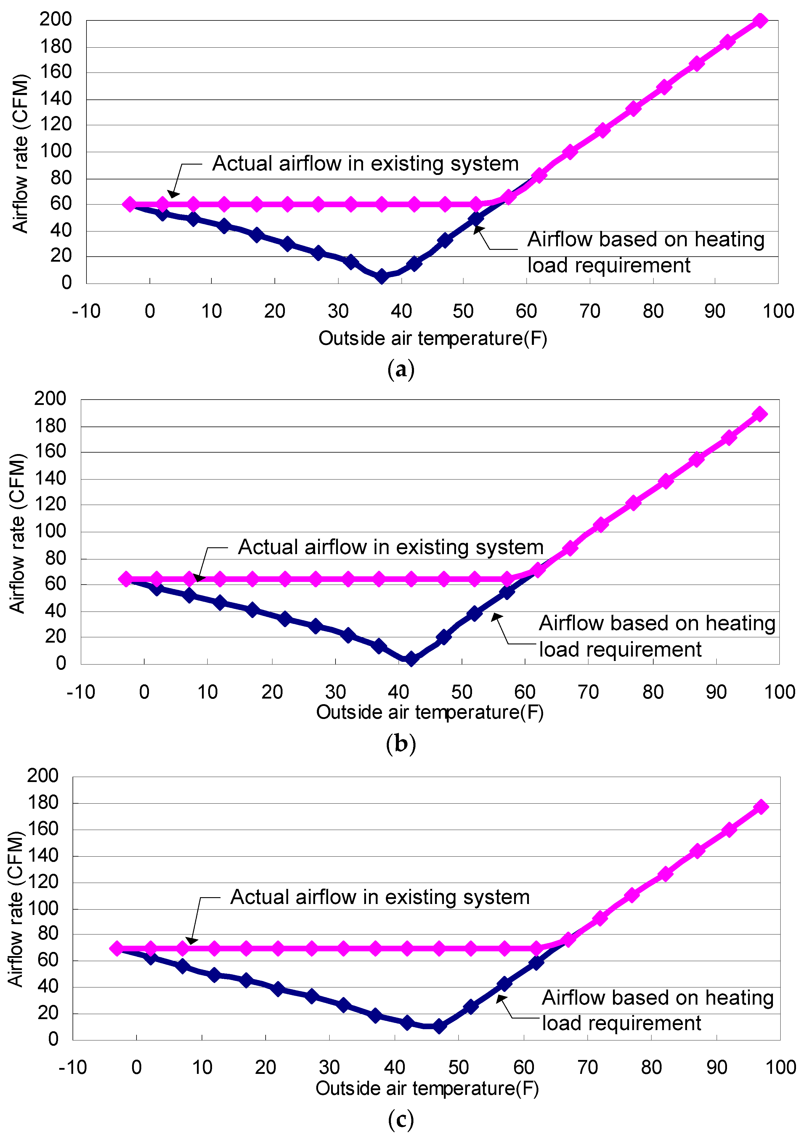
3.1. Minimum Air Flow Based on Heating Load
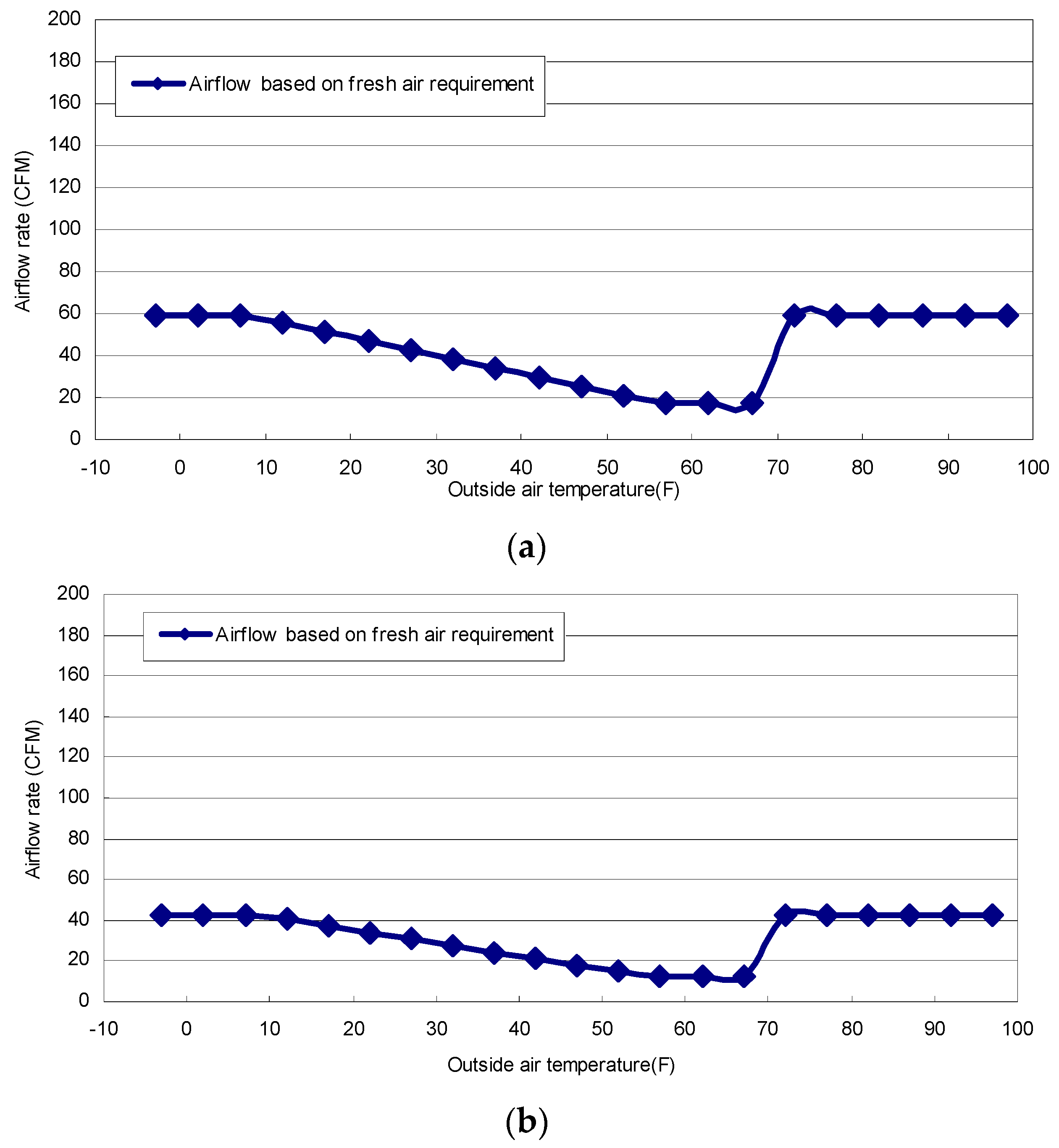
3.2. Minimum Air Flow Based on Ventilation Requirement
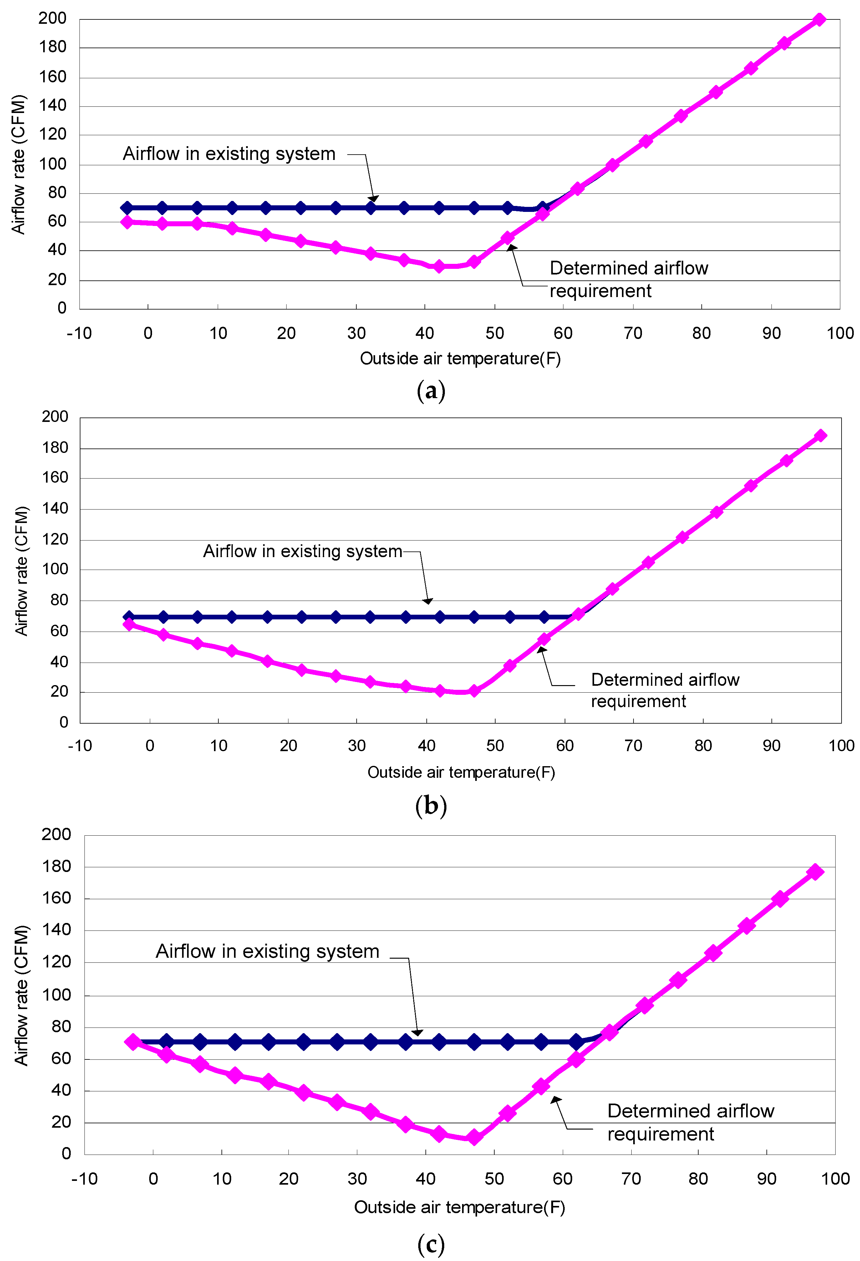
3.3. Minimum Air Flow Requirement
4. Optimal Terminal Box Control Algorithms
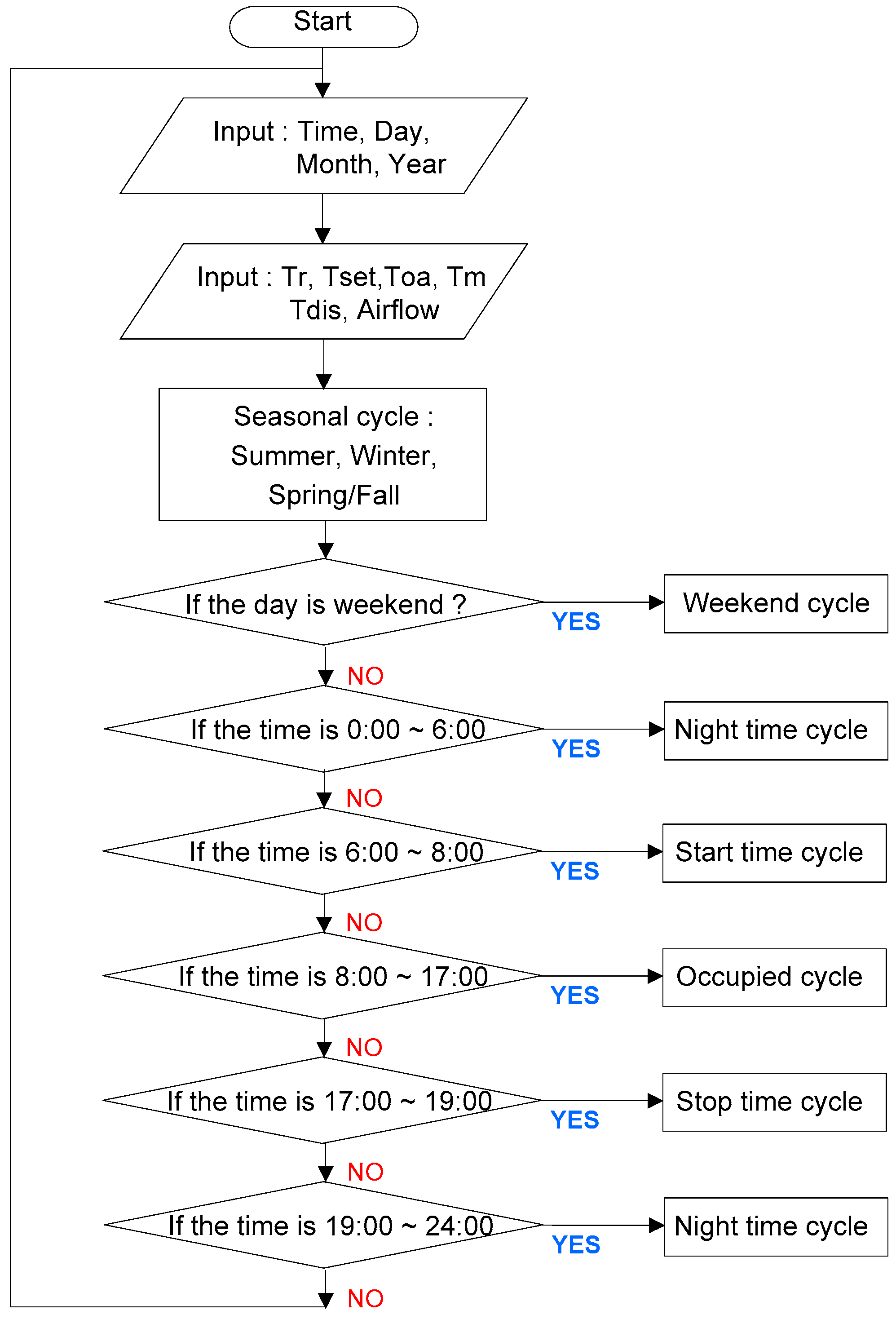
4.1. General Operation Function for an EMCS
- ➢
- Objective: To improve thermal comfort and reduce energy consumption
- ➢
- Definitions:
- Seasonal cycle: summer, winter and spring/fall
- Weekend cycle: the day of the year is a weekend or holiday
- Occupied cycle: the day of the year is a weekday
- Nighttime cycle: the terminal box is disabled
- Start/stop time cycle: before and after working hours
- ➢
- Process:
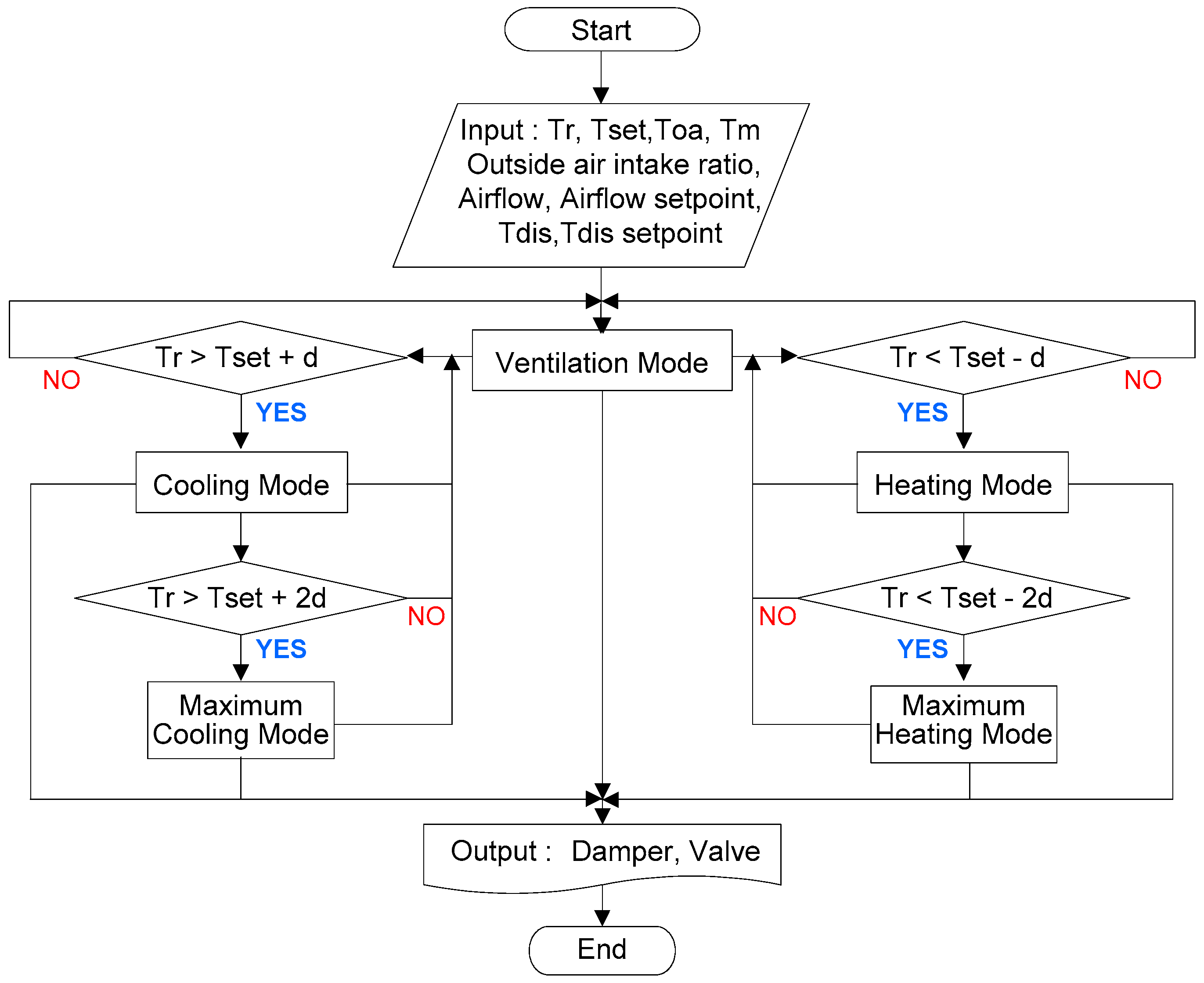
4.2. Occupied Time Operation for EMCS
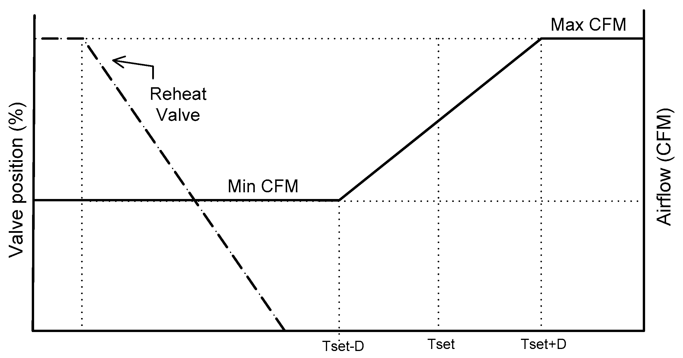
- Ventilation mode: When the room air temperature is equal to its set point deviation (d), the reheat valve is closed; the air flow set point is maintained by the calculated required fresh air intake.
- Cooling mode: When the room air temperature is above its set point deviation (d), the reheat valve is closed; the room temperature set point is maintained by modulating the air flow between the maximum and minimum values.
- Maximum cooling mode: When the room air temperature is above its set point deviation (2d), the reheat valve is closed; the maximum air flow of this mode is higher than that of cooling mode.
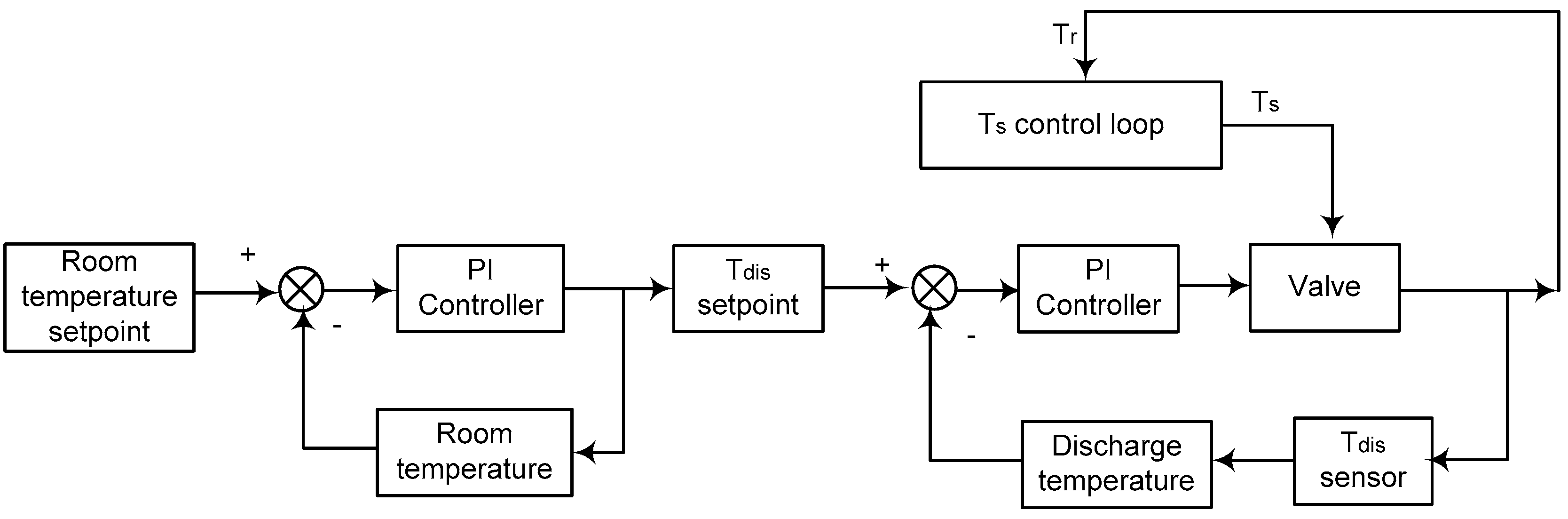
- Heating mode: When the room air temperature is below its set point deviation (d), the discharge air temperature is maintained by modulating the reheat valve between its maximum and minimum set point; the air flow set point is the calculated required ventilation air flow.
- Maximum heating mode: When the room air temperature is below its set point deviation (2d), the air flow is maintained between its maximum and minimum values.
5. Application
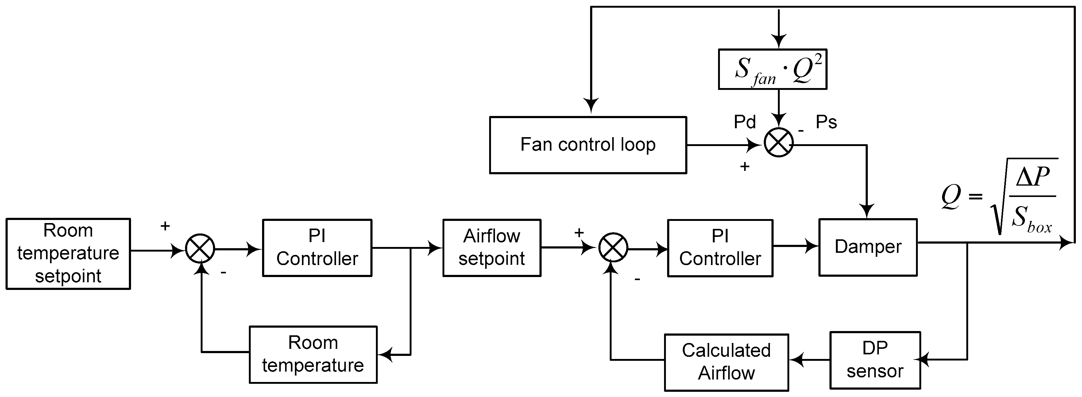
5.1. Conventional Terminal Box Control
5.2. Improved Terminal Box Control
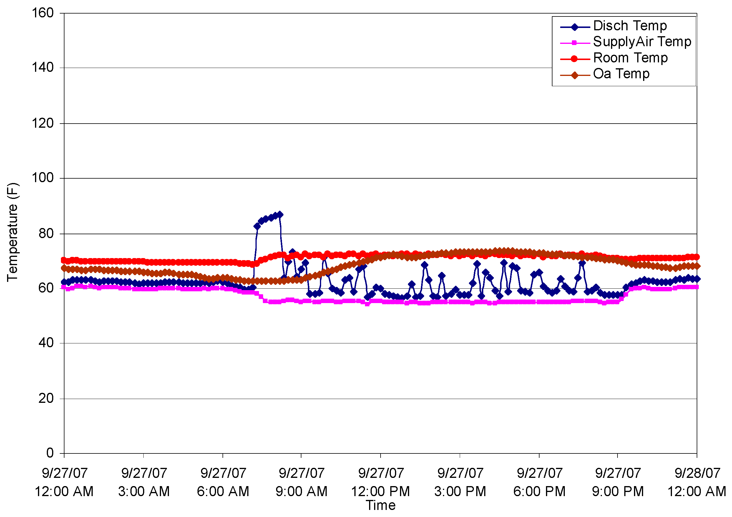
5.2.1. Stability of Room Air Temperature Control
5.2.2. Thermal Comfort
5.2.3. Potential Energy Savings
6. Conclusions
- (1)
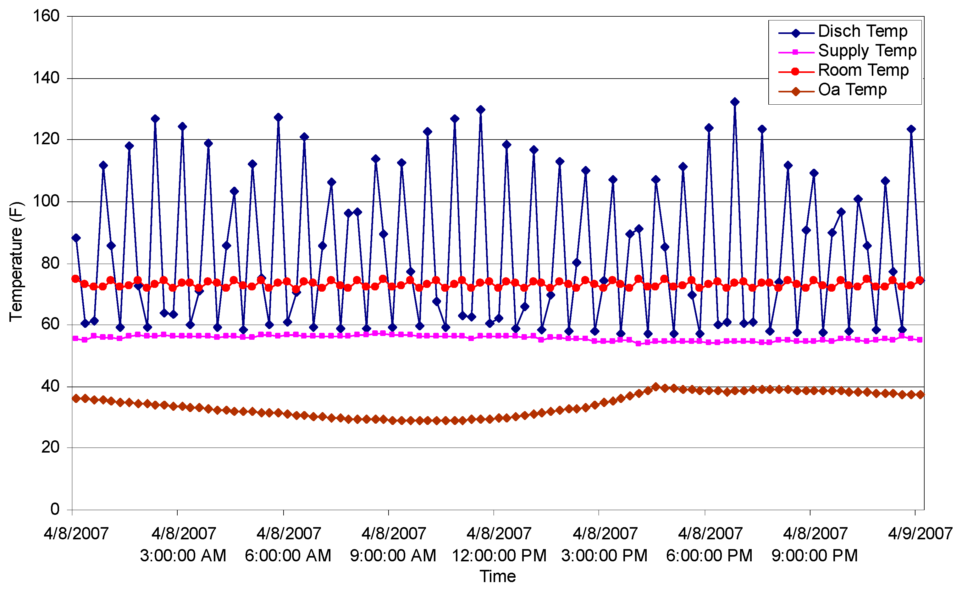
- In conventional control, the room temperature could not maintain its set point because the minimum air flow supplies an inadequate air flow for a conditioned space without considering building operation conditions. The minimum air flow is higher than required, which often leads to significant simultaneous heating and cooling, in addition to excessive fan power.
- (2)
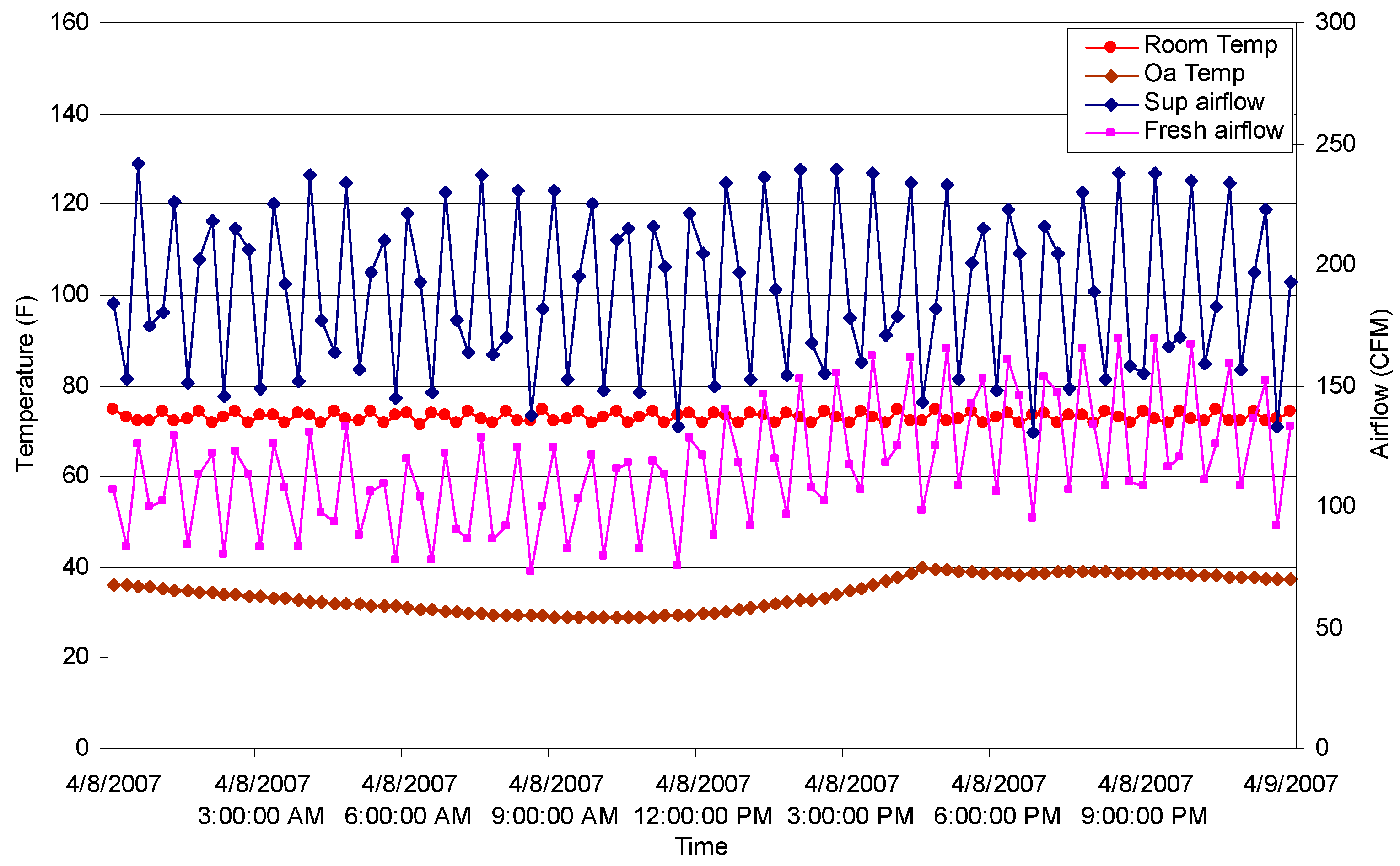
- Improved control can stably maintain the set room air temperature and reduce energy consumption, compared to conventional control. Measurements of CO2 levels show there is no indoor air quality problem when the minimum air flow set point is reduced.
- (3)
- In energy measured results, the thermal energy consumption with improved control is less than that with the conventional control. Therefore, if developed EMCS control algorithms are applied, a terminal box can reduce thermal energy.
Acknowledgments
Author Contributions
Conflicts of Interest
Nomenclature
| Room air temperature, °F | |
| outside air temperature, °F | |
| interior air temperature, °F | |
| internal heat gains, Btu/hr | |
| mass flow rate of ventilation air, lbm/h | |
| standard air density, lbm/ft3 | |
| volume of room air mass, ft3 | |
| specific heat of air, Btu/lbm °F | |
| heat transfer coefficient of exterior wall, Btu/lbm ft2 °F | |
| heat transfer coefficient of interior wall, Btu/lbm ft2 °F | |
| area of exterior wall, ft2 | |
| area of interior wall, ft2 | |
| steady state supply air temperature, °F | |
| steady state discharge air temperature, °F | |
| steady state supply water temperature, °F | |
| steady state return water temperature, °F | |
| mass flow rate of air, lbm/h | |
| mass flow rate of water, lbm/h | |
| specific heat of water, Btu/lbm °F | |
| specific heat of air, Btu/lbm °F | |
| equal to or , whichever is smaller. | |
| equal to or , whichever is bigger. | |
| heat capacity ratio | |
| number of transfer units | |
| heat exchanger effectiveness with both fluids unmixed | |
| dynamic discharge air temperature, °F | |
| dynamic return water temperature, °F | |
| coil time constant | |
| Inlet air pressure | |
| outlet air pressure | |
| air flow resistance coefficient | |
| air flow rate | |
| Inlet water pressure | |
| outlet water pressure | |
| water flow resistance coefficient | |
| water flow rate | |
| air volumetric flow rate for fresh air requirement, ft3/min | |
| AHU outside air intake ratio, % | |
| terminal box air flow resistance | |
| fan power, kw | |
| room enthalpy, Btu/lbm | |
| supply enthalpy, Btu/lbm | |
| minimum air flow ratio in conventional conditions | |
| minimum air flow ratio in improved conditions | |
| supply air flow ratio | |
| fan efficiency | |
| the static pressure set point, in.wg |
References
- Elovitz, D.M. Minimum outside air control method for VAV systems. ASHRAE Trans. 1995, 101, 613–618. [Google Scholar]
- Krakow, K.I. Economizer control. ASHRAE Trans. 2000, 106, 13–25. [Google Scholar]
- Ke, Y.P. Optimized supply air temperature (SAT) in variable-air-volume (VAV) systems. Energy Int. J. 1997, 22, 601–614. [Google Scholar] [CrossRef]
- Zaheer-uddin, M. VAV system model to simulate energy management control functions: Off-normal operation and duty-cycling. Energy Convers. Manag. 1994, 35, 917–932. [Google Scholar] [CrossRef]
- Engdahl, F.; Johansson, D. Optimal supply air temperature with respect to energy use in a variable air volume system. Energy Build. 2004, 36, 205–218. [Google Scholar] [CrossRef]
- Wei, G.; Claridge, D.E.; Liu, M. Optimize the Supply Air Temperature Reset Schedule for a Single Duct VAV system. In Proceedings of the Twelfth Symposium on Improving Building Systems in Hot and Humid Climates, San Antonio, TX, USA, 15–17 May 2000; pp. 154–157.
- Nassif, N.; Moujaes, S. A new operating strategy for economizer dampers of VAV system. Energy Build. 2008, 40, 289–299. [Google Scholar] [CrossRef]
- Taylor, S.T.; Stein, J. Sizing VAV Boxes. ASHRAE J. 2004, 46, 30–35. [Google Scholar]
- Cho, Y.; Liu, M. Minimum air flow reset of single duct VAV terminal boxes. Build. Environ. 2009, 44, 1876–1885. [Google Scholar] [CrossRef]
- Cho, Y.; Liu, M. Correlation between minimum air flow and discharge air temperature. Build. Environ. 2010, 45, 1601–1611. [Google Scholar] [CrossRef]
- Kang, S.; Kim, H.; Cho, Y. A Study on the control method of single duct VAV terminal unit through the determination of proper minimum air flow. Energy Build. 2014, 69, 464–472. [Google Scholar] [CrossRef]
- Kim, H.; Kang, S.; Cho, Y. A study on the control method without stratification of single duct VAV terminal units. J. Asian Arch. Build. Eng. 2015, 14, 467–474. [Google Scholar] [CrossRef]
- Taylor, S.; Stein, J.; Paliago, G.; Cheng, H. Dual maximum VAV box control logic. ASHRAE J. 2012, 54, 16–24. [Google Scholar]
- Zhang, B.; Li, Y.; Lau, J.; Liu, M. Demand control ventilation: Influence of terminal box minimum air flow setting on system energy use. Energy Build. 2014, 79, 173–183. [Google Scholar] [CrossRef]
- American Society of Heating, Refrigerating and Air-Conditioning Engineers (ASHRAE). Ventilation for Acceptable Indoor Air Quality (IAQ); ASHRAE Standard 62.1-2004; ASHRAE: Atlanta, GA, USA, 2004. [Google Scholar]


| Design Air Flow (CFM) | Minimum Air Flow (CFM) | Minimum Air Flow Ratio (%) | |||
|---|---|---|---|---|---|
| Base Case | Improved Case | Base Case | Improved Case | ||
| Fully occupied condition | 200 | 70 | 29–70 | 35% | 14%–35% |
| 50% occupied condition | 200 | 70 | 21–70 | 35% | 11%–35% |
| Unoccupied condition | 200 | 70 | 11–70 | 35% | 6%–35% |
| Mode | Mode Period | Air flow Set Point | Discharge Temperature Set Point | |||
|---|---|---|---|---|---|---|
| Maximum | Minimum | Maximum | Minimum | |||
| Occupied | Ventilation | Tset − d < Tr < Tset + d | CFM_ventilation | CFM_ventilation | Ts | Ts |
| Cooling | Tr > Tset + d | CFM_cooling | CFM_ventilation | Ts | Ts | |
| Maximum cooling | Tr > Tset + 2d | α CFM_cooling | CFM_ventilation | Ts | Ts | |
| Heating | Tr < Tset − d | CFM_heating | CFM_ventilation | Tr + 15 | Ts | |
| Maximum heating | Tr < Tset − 2d | α CFM_heating | CFM_ventilation | Tr + 15 | Ts | |
| Unoccupied | Cooling | Tr > Tset + 4d | CFM_cooling | Zero | Ts | Ts |
| Heating | Tr < Tset − 4d | CFM_heating | Zero | Tr + 15 | Ts | |
| Item | Information | |
|---|---|---|
| EMCS Software | Andover Continuum with Plain English® Programming | |
| Zone | Location Purpose Size | Omaha, Nebraska Office room Floor area: 215 ft2, Volume: 1550 ft3 |
| People | Number Schedule | Normally one Person during occupied hour Occupied hours (8:00 a.m.–6:00 p.m.) |
| Operation condition | HVAC system AHU supply air temperature Supply hot water temperature Room set point | 24 h, 7 days working 55 F 140 F 73 F |
| EMCS control point | AHU Input | Outside air temperature Mixed air temperature Supply air temperature Return air temperature |
| Terminal box Input | Space room air temperature Discharge air temperature Air flow rate | |
| Terminal box Output | Damper position Reheating valve position | |
| Terminal box information | Type | Single-duct pressure independent terminal box with hydronic reheat coil |
© 2016 by the authors; licensee MDPI, Basel, Switzerland. This article is an open access article distributed under the terms and conditions of the Creative Commons Attribution (CC-BY) license (http://creativecommons.org/licenses/by/4.0/).
Share and Cite
Seong, Y.-B.; Cho, Y.-H. Development and Evaluation of Applicable Optimal Terminal Box Control Algorithms for Energy Management Control Systems. Sustainability 2016, 8, 1151. https://doi.org/10.3390/su8111151
Seong Y-B, Cho Y-H. Development and Evaluation of Applicable Optimal Terminal Box Control Algorithms for Energy Management Control Systems. Sustainability. 2016; 8(11):1151. https://doi.org/10.3390/su8111151
Chicago/Turabian StyleSeong, Yoon-Bok, and Young-Hum Cho. 2016. "Development and Evaluation of Applicable Optimal Terminal Box Control Algorithms for Energy Management Control Systems" Sustainability 8, no. 11: 1151. https://doi.org/10.3390/su8111151
APA StyleSeong, Y.-B., & Cho, Y.-H. (2016). Development and Evaluation of Applicable Optimal Terminal Box Control Algorithms for Energy Management Control Systems. Sustainability, 8(11), 1151. https://doi.org/10.3390/su8111151