Abstract
As the rock fracture in the roof anchorage blind zone of coal roadway develops, it not only brings about serious deformation, but also results in barrier effect on anchorage stress, restricting the efficiency of the bolt support. In this paper, the existence and formation mechanism of the anchorage blind zone in the roadway roof supported by prestress bolt are found. Through field research, theoretical analysis, and numerical simulation, the main control influencing factors of the anchorage blind zone are studied. Results show that stress of rock mass in the anchorage blind zone increases with stronger bolt prestress and decreases with longer bolts (free-segment length); the length of the free segment is the main control factor that affects the range of the anchorage blind zone. Moreover, the corresponding control countermeasures are put forward that properly increasing the bolt prestress and shortening the free segment can effectively increase the stress value of the rock mass in the anchorage blind zone and reduce the scope of the zone. Under the condition of high prestress of the anchor bolt, how to reasonably select the thickness of the anchor layer so as to control rock mass deformation not only in the anchorage blind zone but also in the whole anchorage area at the same time is the key. Based on the surrounding mining conditions of the test roadway, the working method is proposed that uses a high-prestress cable to construct the roof thick anchor layer as well as a short bolt to strengthen the shallow rock mass of the roof so as to improve the bearing performance of the rock mass in the free segment, especially in the anchorage blind zone. Field validation demonstrated that the proposed strategy not only suppresses the “net pocket” phenomenon but also enhances resource efficiency by optimizing material usage (e.g., reduced bolt length and targeted prestress allocation). This approach contributes to sustainable mining practices by extending roadway service life and minimizing frequent maintenance, thereby reducing long-term environmental impacts associated with roof failures.
1. Introduction
With the increase in mining depth and the complexity of the mining stress environment [1,2,3], the separation fractures of roadway roof strata are badly developed, resulting in serious damage, increased deformation sensitivity, reduced bearing performance, and difficulty of support. These challenges not only threaten operational safety but also escalate resource consumption and environmental risks due to frequent maintenance, highlighting the need for sustainable solutions in coal roadway support. In fact, the counted coal mine accidents mostly occur in roadway roof strata, resulting in unpredictable consequences [4]. Therefore, how to effectively maintain and control the stability of roadway roof strata under an increasingly complex mining environment and more difficult support conditions has become a key technical problem restricting the efficient mining of coal.
Extensive research has been conducted on deformation instability and control technologies for roadway roof strata. Wu et al. analyzed the progressive deterioration of mining roadway roofs, highlighting that flexural deformation of roof rocks induces horizontal displacement, leading to anchor cable shear fractures and roof instability. They proposed reinforcement accessories to enhance anchor bolt prestress and suppress horizontal displacement beyond the anchorage zone, achieving successful field applications [5]. Coggan et al. emphasized the adverse impacts of high horizontal stress and weak lithology in direct roofs, concluding that the thickness of weak mudstone layers critically influences roof damage severity and reinforcement requirements [6]. Frith et al. suggested optimizing roof anchorage systems by either attenuating or enhancing the natural self-supporting capacity of horizontal layered strata, thereby improving anchorage efficiency [7]. Kang et al. investigated fracture mechanics under high abutment loads, proposing that shear sliding arises from tensile cracking of intact rock combined with slippage along bedding planes and cross joints. Such sliding occurs when support loads are significantly lower than the roof’s compressive strength [8]. Shen et al. developed an integrated monitoring system combining displacement, stress, and seismic measurements for longwall face roadway stability. This system successfully captured critical roof behaviors in real time [9]. Wang et al. conducted field tests in complex geological zones, demonstrating that large roadway deformations and roof collapse driving forces primarily stem from high tectonic stress and fault slippage [10]. Yan et al. explored bedding separation mechanisms in thick coal seam roofs, introducing a novel BSR (bedding separation region) prediction method based on the continuous–discontinuous beam theory and strata load experiments [11]. Yuan et al. studied roadway deformation under intense mining conditions, proposing a “thick anchoring–cross-boundary support” principle validated by field monitoring data [12]. Yang et al. quantified the effects of roadway depth, roof thickness, and unsupported spans on stability, determining the maximum allowable unsupported distance during excavation to enhance tunneling efficiency [13]. Mazurek et al. identified limitations in conventional support systems for deep roadways, where stress concentration and deformation persist. They designed a frame-type support structure with initial bearing capacity to address these challenges [14]. Colwell and Frith validated horizontal stress-driven slender beam behavior and vertical stress-driven columnar mechanisms as dominant instability modes in composite roof roadways [15].
Yu et al. established mathematical models for composite roof damage parameters and layer deflection/spacing, demonstrating that active bolt support significantly enhances surrounding rock stability [16]. Li et al. introduced an energy evolution-based method to determine roof caving zone heights and failure areas, guiding bolt–anchor cable length and angle optimization [17]. Wang et al. elucidated the composite failure mechanism in bolted roof supports by integrating delamination and nonlinear rock failure characteristics, verifying simplified design methods through industrial trials [18]. Zhang et al. derived mathematical expressions for support load settings and active column lengths under high abutment pressure, emphasizing the necessity of coupling support strength with anchored rock deformation for long-term stability [19].
Previous studies have extensively investigated deformation mechanisms and control strategies for roadway roof strata, emphasizing global structural stability through optimized bolt–cable systems. However, these approaches predominantly overlook localized weaknesses in prestressed bolt systems, particularly the short plate effect caused by the anchorage blind zone—a triangular low-stress region in shallow roof strata between adjacent bolts. Conventional methods, such as adjusting bolt spacing or grouting, fail to address its instability under cyclic mining disturbances. As shown in Figure 1, deformation and fragmentation within this zone trigger the “net pocket” phenomenon, disrupting stress transfer, weakening anchorage performance, and initiating progressive loosening of compression zones. This study identifies the existence of the anchorage blind zone—a triangular low-stress region in shallow roof strata between adjacent prestressed bolts—and elucidates its formation mechanism through theoretical analysis. By integrating numerical simulations, we quantitatively establish the primary control factors: bolt prestress (positively correlated) and free-segment length (inversely correlated), thereby delineating the zone’s scope. Building on these findings, we propose a novel dual-mechanism support strategy combining high-prestress cables to anchor deep stable strata and short bolts to reinforce shallow rock masses. This approach uniquely addresses the “short plate effect” of the anchorage blind zone by mobilizing deep strata to constrain shallow displacements while enhancing localized self-bearing capacity. Validated through field tests in the Hulusu Coal Mine, this strategy eliminates separation fractures and ensures stable load distribution in cables and bolts without mutual interference, effectively suppressing the “net pocket” phenomenon. These contributions advance the design of prestressed bolt systems and provide a scalable framework for roof stability control in deep, high-stress mining environments.
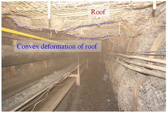
Figure 1.
The “net pocket” phenomenon of the roof anchor support.
2. Formation Mechanism of the Roof Anchorage Blind Zone
The prestress bolt forms an approximate rhombic anchorage zone in the free segment of the roof (the compression zone in Figure 2a), making the rock mass change from a two-way stress state to a three-way stress state, which significantly improves the bearing performance of the rock mass [20]. However, in the shallow part of rock strata between adjacent prestress bolts, there exists a triangle area with weak anchoring effect (Figure 2b), that is, the triangle anchorage blind zone in the Figure. The width of the anchorage blind zone is generally the spacing or row spacing of the anchor bolts. Usually, it can remain stable under the influence of the rock mass in the compression zone formed by two adjacent anchor bolts. However, when the rock mass is weak or suffered from disturbed stress, the anchorage blind zone is often deformed and broken, finally showing the “net pocket” phenomenon. The adverse effect of anchorage blind zone on roof support control is obvious. When the anchorage blind zone is deformed and broken, the lower rock mass of the compression zone escapes from constraint, resulting in the relaxation of the anchorage force, all of which leads to the gradual loosening of the compression zone and the reduction of the roof anchorage performance.
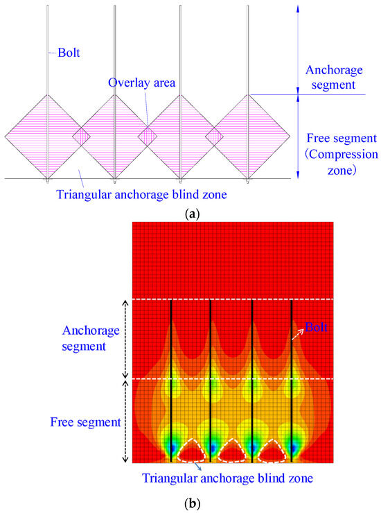
Figure 2.
Diagram of anchorage blind zone of prestress bolt: (a) Theoretical concept map and (b) stress contour plots.
3. The Influence Law of Support Parameters on the Anchorage Blind Zone
The main supporting influencing factors of an anchorage blind zone include bolt length, bolt prestress, and row spacing between bolts. As mentioned above, the width of the anchorage blind zone between adjacent bolts is generally the spacing between bolts. Accordingly, the width and range of the anchorage blind zone can be effectively reduced by appropriately reducing the spacing between bolts. In this section, the influence of bolt length and prestress on the anchorage blind zone is studied.
3.1. Analysis on Influencing Factors of Main Control Support in the Anchorage Blind Zone
As mentioned above, the prestress bolt forms an approximate rhombic compression zone in the rock mass. Researching the influence law of bolt length and prestress on the compression belt is helpful in the research on the anchorage blind zone.
A mechanical model is established based on the quarter plane of the rock mass strengthened by a single bolt (Figure 3), in which the x-axis represents the horizontal distance from a point in the rock mass to the center of the bolt, and the y-axis represents the axial vertical distance of the bolt.
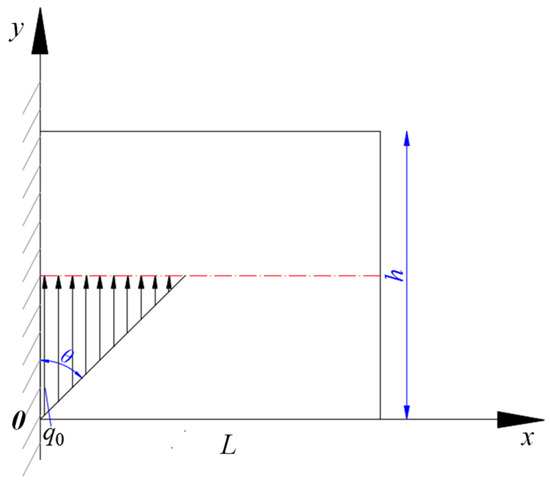
Figure 3.
Effect of bolt forming load on a rock stratum in a 1/4 plane.
It is considered that force F generated by the anchor bolt in the compression belt is linearly distributed along the anchorage angle θ. The rock layer with a length of L that is not affected by the force is taken as the free end, and the material mechanics formula is derived as follows:
Accordingly, the fixed end reaction force f:
The shearing force FS and moment of force M(x):
Taking x = 0, M(x) = 0 into Formula (7), c = 0, which renders
It can be seen from Formulae (8) and (9) that the stress formed by the bolt in the rock mass of the compression zone is proportional to the bolt force F and inversely proportional to the thickness h2 of the anchoring layer. The stress of the rock mass in the compression zone increases with an increase in prestress and decreases with an increase in bolt length (the length of the anchorage segment remains unchanged, but the length of the free segment increases). It can be inferred from the force–effect relationship that the rock stress in the triangular anchorage blind zone below the compression zone is positively correlated with the rock stress in the compression zone and is negatively correlated with the free-segment length of the bolt. That is, the rock stress in the triangular anchorage blind zone increases with an increase in prestress and decreases with an increase in the free-segment length.
3.2. Verification of the Numerical Simulation
3.2.1. Establishment of a Numerical Model
In order to verify and analyze the stress influence law of bolt length and prestress on anchorage blind zone, FLAC3D numerical calculation model is established (Figure 4). The size of the model is 3 m in x-direction, 2 m in y-direction, and 6 m in z-direction. To ensure the computational accuracy of the numerical model, grid refinement was implemented by adopting reduced mesh sizes: the refined grid dimensions are 0.1 m in the x-direction, 0.1 m in the y-direction, and 0.1 m in the z-direction. The upper and bottom boundaries of the model are fixed in the vertical direction, meanwhile, the left and right boundaries are fixed in the horizontal direction without displacement. Since we only study the prestress field of the bolt anchorage in a rock mass, each boundary is not applied with the load, and the Mohr–Coulomb yield criterion is adopted. The parameters of the model are shown in Table 1.
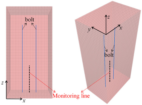
Figure 4.
Numerical simulation model.

Table 1.
Distribution and mechanical parameters of strata.
3.2.2. Influence of Prestress on the Anchorage Blind Zone
- Simulation calculation scheme
In the simulation calculation of this group, two bolts are installed at the lower boundary of the model (z = 0, x = 1, 3), and the bolt spacing is 1 m. There are five numerical calculation schemes, among which the prestress of the anchor bolt is variable, and other supporting parameters are equal. For the anchor bolt, the length is 4 m, the diameter is 22 mm, and the yield load is 600 MPa. The length of the anchorage segment and the free segment are both 2 m. Within the five schemes, the prestress values are 60 kN, 120 kN, 180 kN, 240 kN, and 300 kN, respectively.
- 2.
- Monitoring methods and results
In the simulation calculation, the monitoring objects are the vertical stress distribution nephogram, which is located at the section y = 0.82 and the section z = 0.2, and vertical stress value at the shallow anchorage blind zone between the two anchors (Figure 4). Monitoring results are shown in Figure 5 and Figure 6, respectively.
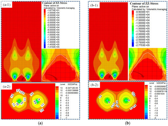
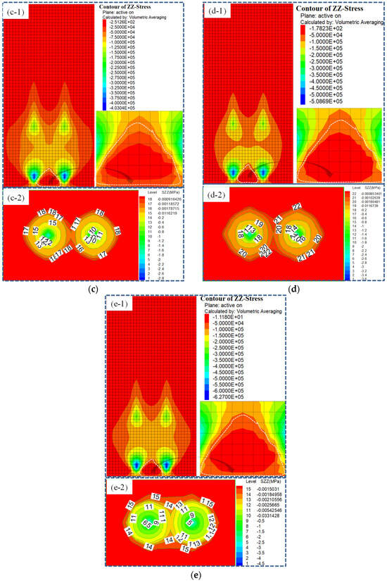
Figure 5.
Vertical stress contour plots distribution of the anchorage blind zone in different bolt pre-tension schemes: (a) Pre-tension of bolt 60 kN; (b) pre-tension of bolt 120 kN; (c) pre-tension of bolt 180 kN; (d) pre-tension of bolt 240 kN; (e) pre-tension of bolt 300 kN.
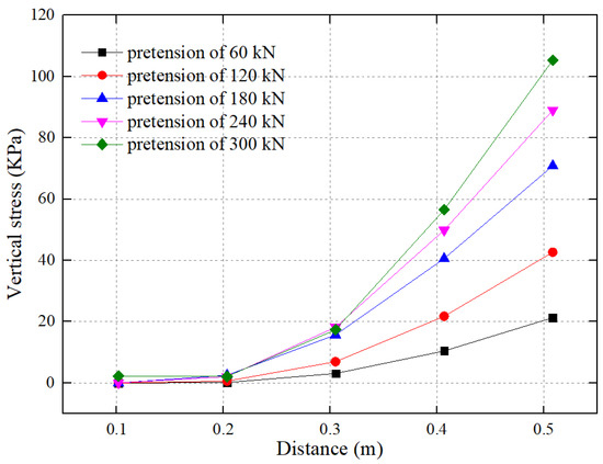
Figure 6.
Numerical distribution curves of vertical stress in the anchorage blind zone of different anchor pre-tension schemes.
- The prestress field created by two bolts overlaps with each other and finally forms into a triangular low value stress region with a height of about 50 cm in the shallow area of the rock stratum, which verifies the formation mechanism of the anchorage blind zone described above.
- Under the fixed bolt length (free-segment length), with an increase in anchor pre-tension, the area of the triangular anchorage blind zone shows no obvious increase or decrease, but the vertical stress value of the rock mass in the anchorage blind zone increases accordingly (Figure 5(a-1–e-1)).
- According to the nephogram of the anchor stress ring, as prestress increases, the range of the anchor stress ring shows no obvious increase, but the stress value represented by the stress ring increases gradually (Figure 5(a-2–e-2)).
- With an increase in bolt prestress, the value of vertical stress in the anchorage blind zone gradually increases from the shallow middle position to the deep (Figure 6), which verifies the law revealed in Figure 5 and the theoretical calculation results in Section 3.1.
3.2.3. Effect of Bolt Length on the Anchorage Blind Zone
- Simulation calculation scheme
In the simulation calculation of this group, two bolts are installed at the lower boundary of the model (z = 0, x = 1, 3), and the bolt spacing is 1 m. There are five numerical calculation schemes, among which the bolt length is variable, and other supporting parameters are equal. For the anchor bolt, the pre-tension is 200 kN, the diameter is 22 mm, the yield load is 600 MPa, and the length of the anchor segment is 2 m. Within the five schemes, the lengths of bolts are 3.0 m (free-segment length is 1 m), 3.5 m (free-segment length is 1.5 m), 4.0 m (free-segment length is 2.0 m), 4.5 m (free-segment length is 2.5 m), and 5.0 m (free -segment length is 3.0 m), respectively.
- 2.
- Monitoring methods and results
The monitoring method is the same as that described in Section 3.2.2, and the monitoring results are shown in Figure 7 and Figure 8, respectively.
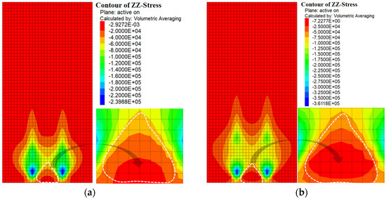
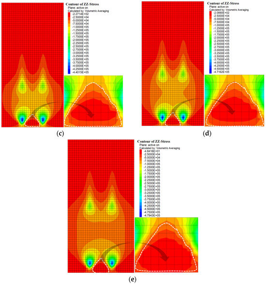
Figure 7.
Vertical stress contour plots distribution of the anchorage blind zone in different bolt length schemes: (a) Bolt length of 3.0 m; (b) bolt length of 3.5 m; (c) bolt length of 4.0 m; (d) bolt length of 4.5 m; (e) bolt length of 5.0 m.
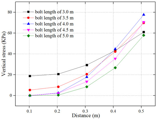
Figure 8.
Numerical distribution curve of vertical stress in the anchorage blind zone in different bolt length schemes.
- Under the condition of the fixed prestress and bolt length, increasing the length of the bolt means increasing the length of the free segment. At this time, the prestress diffuses to a wider range of rock, making more rock compressed, which improves the bearing performance of the rock mass. However, with an increase in the diffusion range of prestress, the peak value of bolt prestress in the shallow part of the rock mass will decrease.
- With an increase in bolt length (the length of the anchor segment remains unchanged and the length of the free segment increases), the value of vertical stress in the anchorage blind zone gradually decreases from the shallow to the deep (Figure 8), which verifies the law revealed in Figure 7 and the theoretical calculation results in Section 3.1.
4. Analysis on Control Countermeasures of the Anchorage Blind Zone
Generally, the control countermeasures of the anchorage blind zone are as follows: (1) increase the density of bolt support and reduce the range of the anchorage blind zone; (2) equip a steel belt with higher performance to diffuse prestress and anchorage force to a wider range of rock mass; (3) shallow hole grouting to improve the strength of shallow surrounding rock. Even though these countermeasures have been successfully applied in the project site, some of them are more complex to construct, which influences the efficiency of overall construction.
This paper found that properly increasing the bolt prestress and shortening the bolt length (free-segment length) can effectively improve the stress value and self-bearing performance of the rock mass in the anchorage blind zone. At the same time, shortening the length of anchor bolt (free-segment length) will also reduce the range of the anchorage blind zone.
As the key technology of bolt support, increasing prestress can enhance the self-stability of the rock mass not only in the anchorage blind zone, but also in the whole anchorage area. However, for the choice of bolt length, several engineering cases have shown that longer bolts can pass through the rock fracture circle to stable rock strata with small deformation, that is, restrain the large displacement of the shallow rock strata through the small displacement of the deep rock strata, realizing the linkage between large displacement and small displacement, which can effectively control the roof deformation. Therefore, the critical solution relies on how to reasonably select the thickness of anchorage strata to control the rock mass deformation both in the blind zone and in the whole anchorage zone.
5. Industrial Test of Support and Control Anchorage Blind Zone with High Efficiency
5.1. Project Overview
- Roadway location and basic conditions
The Hulusu Coal Mine in Ordos City, Inner Mongolia Province, China, with a buried depth of 650–900 m and the thickness of 0.67–6.37 m in the main coal seam, the 2-1 coal seam, is studied. The working face 21102 is the first working face in panel 1 of the coal seam 2-1, with an average buried depth of 626.65 m and an average thickness of 2.8 m. The mining layout of “double roadways” is adopted, in which the distance between the auxiliary air-return roadway 21102 and the working face 21102 is 30 m (Figure 9).
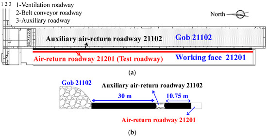
Figure 9.
The layout of the test roadway: (a) Roadway layout plan view and (b) roadway layout profile view.
According to the original plan, after mining the working face 21101, the auxiliary air-return roadway 21102 would be used as the air-return roadway of the next working face (working face 21201). However, due to the influence of mining of the working face 21102, the auxiliary air-return roadway 21102 is seriously deformed and fails to meet the mining needs of the working face. According to the new plan, the air-return roadway 21201 is re-excavated by setting a 10.75 m coal pillar at the edge of the air-return roadway 21201. Since the new air-return roadway is located at the lateral edge of the goaf 21102, which undertakes lateral residual abutment stress, it also belongs to the deep buried high stress mining roadway.
- 2.
- Lithology of the coal seam roof and floor
The coal seam roof is mainly composed of sandy mudstone, fine-grained sandstone, and siltstone, with a multi-layer thick-and-hard roof; the coal seam floor is mainly sandy mudstone. The direct roof of the coal seam is 3.96 m sandy mudstone, and the basic roof is 13.01 m fine-grained sandstone. The specific rock strata occurrence structure of coal seam roof and floor is shown in Figure 10.
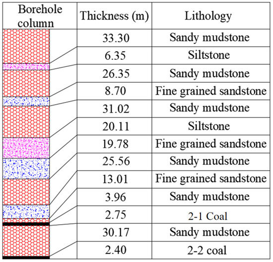
Figure 10.
The rock strata occurrence structure of the coal seam roof and floor.
5.2. Analysis of Control Countermeasures
As mentioned above, the air-return roadway 21201 belongs to the deep buried high stress mining roadway, whose surrounding rock is seriously damaged, and cracks are developed as a result of mining influence of the working face 21101. After the roadway excavation, the stress distribution of surrounding rock is adjusted again, resulting in certain damage and cracks to the roadway roof. It is necessary to build a fundamental support with thicker anchor strata and higher anchor performance in the roof.
For the conventional resin anchor cable, the length of resin roll bonding anchorage segment cannot be extended to the shallow rock mass due to the constraints of many factors. With the increase of bolt length, the free segment will inevitably become longer, and the axial sensitivity of the bolt and anchor cable (the ability to restrain deformation) will be reduced.
The theoretical analysis and numerical simulation results show that increasing the bolt length (increasing the free-segment length, meanwhile, anchorage segment length unchanged) cannot effectively improve the bearing performance of rock mass in the shallow anchorage blind zone. Therefore, on the basis of establishing the fundamental support with thick anchor strata in the roof, it is still necessary to use short anchor bolts in the shallow part of the roof rock mass. The combination of fundamental support and short bolts can not only improve the bearing performance of the free segment of the thick anchorage strata but also improve the self-bearing performance of the rock mass in the shallow anchorage blind zone. Control countermeasures are formed as follows:
- The fundamental roof support adopts a high prestress anchor cable, which can build a roof thick anchor layer to the stable rock stratum with small deformation, stimulating the bearing capacity of a deep rock mass. That is to say, small displacement of a deep rock mass is used to limit the large displacement of a shallow rock mass so as to realize the displacement linkage between shallow and deep strata.
- For the roof thick anchor layer, we increase the length of the high prestress resin roll in the anchorage segment to ensure its anchorage reliability and restrict longer free segment, which can effectively control rock deformation both in the free segment and the anchorage blind zone.
- Based on the construction of a roof thick anchor layer, short bolts are used to strengthen the shallow rock mass of the roof so as to improve the bearing performance of the rock mass in the free segment, especially the anchorage blind zone.
- In order to avoid the interference of short bolts on the cable and effectively control the cable anchorage blind zone, the short bolts shall be arranged near the diagonal formed by the two rows of anchor cables (Figure 11a,b). At this time, the short bolts form a compression belt in the shallow part of the roof rock stratum and the anchorage blind zone, overlapping with the compression belt formed by the anchor cable (Figure 11b,c), which effectively control the stability of the rock stratum both in the shallow part of the roof and the cable anchorage blind zone.
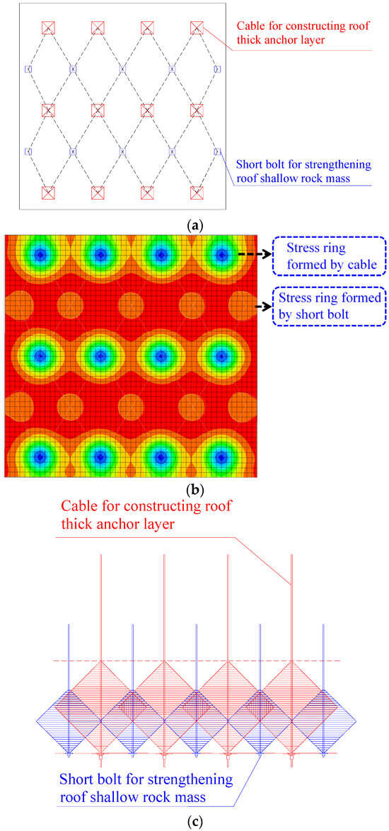 Figure 11. Support and control countermeasures for the roof: (a) Schematic diagram of roof support—top view; (b) stress contour plots of roof support—top view; (c) theoretical model drawing of roof support—front view.
5.3. Supporting Scheme
- Roof supporting
- Anchor cable supporting: Each row adopts four Φ21.8 × 4300 mm anchor cables to build a roof thick anchor layer, the row spacing of anchor cables is 2000 mm, and all are installed perpendicular to the roof rock surface. The cables are anchored with a resin anchoring agent, with the length of the anchorage segment is 1700 mm, and the pre-tension is 200 kN.
- Bolt supporting: After using anchor cables to build a thick anchor layer, five Φ22 × 2500 mm left-hand steel bolts are adopted between each two rows of cables to strengthen the shallow rock stratum of the roof. The bolts are arranged near the diagonal formed by two rows of anchor cables. The row spacing of bolts is 2000 mm, the shoulder angle anchor bolts on both sides are installed with self-aligning ball pads at an inclination of 15°, and all the rest of the bolts are installed perpendicular to the roof rock surface. Like the anchor cable, the bolts are also anchored with a resin anchoring agent, with the length of the anchorage segment is 850 mm, and the pre-tension is 60 kN.
- Coal side supporting
- Bolt supporting: Three Φ22 × 2800 mm left-handed steel bolts are used for each row of the two sides. The row spacing of anchor bolts is 1000 mm, the shoulder angle anchor bolts on both sides are installed with self-aligning ball pads at an inclination of 15°, and all the rest bolts are installed perpendicular to the roof rock surface. The bolts in coal sides are also anchored with a resin anchoring agent, with the length of the anchorage segment is 850 mm, and the pre-tension is 60 kN.
- Anchor cable supporting: Two Φ21.8 × 4300 mm anchor cables are used between each two rows of bolts in coal pillar sides to strengthen supporting. The row spacing of anchor cables is 1000 mm, and two anchor cables are equipped with self-aligning ball pads, which are installed at an inclination of 20°. The cables are also anchored with a resin anchoring agent, with the length of the anchorage segment is 1700 mm, and the pre-tension is 200 kN. The specific support parameters are detailed in Figure 12.
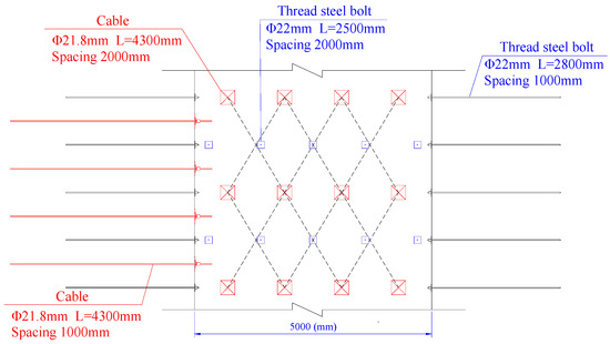 Figure 12. Roadway support scheme—top view.
5.4. Effect Analysis
In order to monitor the control effect of the supporting scheme on roof strata, two monitoring stations for roof separation fracture and one monitoring station for working load of anchor bolts and cables are arranged. As shown in Figure 13, the first roof separation fracture monitoring station is arranged at 683 m away from the roadway opening position, numbered a#; the second roof separation fracture monitoring station is arranged at 1390 m away from the roadway opening position, numbered b#; the anchor bolt and cable working load monitoring station is arranged at 2430 m away from the roadway opening, numbered CL#.
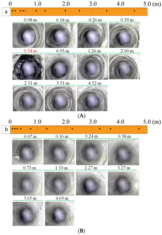
Figure 13.
Monitoring results of separation fractures in roof strata: (A) Monitoring results of the station numbered a#; (B) Monitoring results of the station numbered b#.
In the anchor bolt and cable working load monitoring stations, some dynamometers are installed in the roof anchor cable and the surrounding bolts to monitor the real-time working load of the anchor bolt and cable.
5.4.1. Roof Separation Fractures Monitoring
As shown in Figure 13A, the integrity of the roof rock stratum reflected by borehole peeping of the a# monitoring station is 5 m deep, and no separation fractures development is found in the shallow rock stratum (within 0–0.39 m). It is worth noting that the integrity of the rock stratum is slightly low at the depth of 0.54 m due to the existence of a thin coal seam. For the b# monitoring station, the peep depth is also 5 m, the rock strata inside and outside the anchor cable anchorage zone (0–4.52 m) are relatively integral, without separation fractures development. The rock stratum at the depth within 0.54–4.52 m of the roof has good integrity, without separation fractures development.
The monitoring results of roof separation fractures show that the support technology of first using high prestress cables to construct a roof thick anchor layer and then using short bolts to strengthen the rock mass in the cable free segment and the shallow anchorage blind zone can effectively control the development of separation fractures inside and outside the roof cable anchorage zone.
Moreover, the technology not only effectively guarantees the stability of the roof strata but also limits the expansion and deformation of the shallow rock mass of the roof, especially the rock mass in the anchorage blind zone, all of which ensures the overall integrity of the roadway roof (Figure 14).
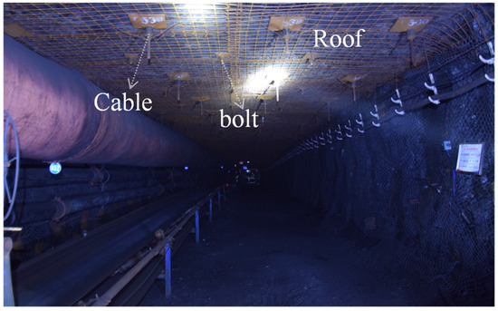
Figure 14.
Photos of the roadway roof during excavation.
5.4.2. Working Load of Anchor Bolts and Cables
According to the monitoring results (Figure 15), for the anchor cable, with the influence of excavation pressure, the working load increases rapidly at the initial stage of installation and then tends to be stable. The stable value is 245 kN, which is higher than the initial pre-tension (200 kN), indicating that the thick anchor layer constructed by anchor cable can mobilize the deep rock stratum of the roof to participate in bearing, so as to give full play to the bearing performance of the anchor cable.
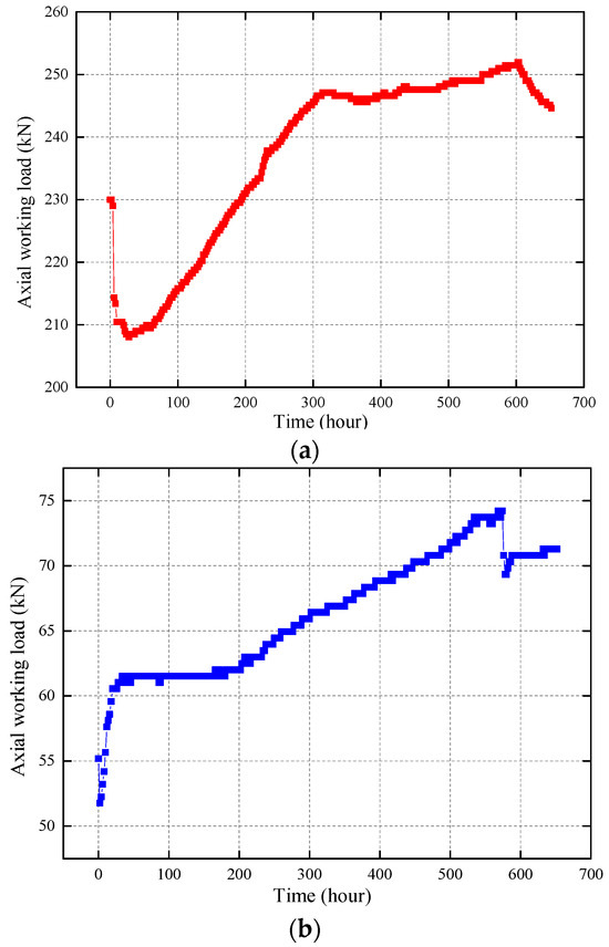
Figure 15.
Monitoring results of the working load of anchor bolts and cables: (a) Monitoring results of the anchor cable working load; (b) Monitoring results of the bolt working load.
For short bolts, the working load increases rapidly at first, then tends to be stable, and finally increases with a uniform speed. The first two stages are similar to the anchor cable. In the third stage, the uniform increase in working load is the result of supporting resistance caused by limiting the deformation of the shallow rock stratum, with the maximum supporting resistance of 74 kN so as to effectively ensure the overall stability of the shallow rock mass of the roof. In summary, both the anchor cable and bolt show great anchoring bearing performance, and the anchoring force does not interfere with each other, which verifies the feasibility of such bolt–cable combination support and layout arrangement.
6. Discussion
This paper studied the influencing factors of control and support in the anchorage blind zone, among which the bolt length and prestress were mainly discussed. Theoretical analysis and numerical simulation results show that with an increase in prestress, the range of the anchorage blind zone between bolts shows no obvious change; meanwhile, the stress value in the anchorage blind zone increases, that is, increasing prestress can improve the bearing performance of the rock mass in the anchorage blind zone. As the bolt length increases (the length of anchorage segment remains unchanged, and the length of free segment increases), the range of the anchorage blind zone increases; meanwhile, the stress value in the anchorage blind zone decreases.
Therefore, under a fixed anchorage length, increasing the bolt length (increasing the free-segment length) cannot effectively control the stability of the rock mass in the anchorage blind zone. It is worth noting that this paper does not discuss the influence of increased bolt length (increasing the length of the anchorage segment) on the rock mass in the anchorage blind zone under a fixed free-segment length. It can be inferred that if prestress and free-segment length are both fixed, increasing the bolt length would have little influence on the range of the anchorage blind zone and the bearing performance of the rock mass in it. However, for the roadway roof control, it is unreasonable to only consider shallow rock strata and the anchorage blind zone. Moreover, it has been successfully verified in the engineering site that the support technology of the roof thick anchor layer can control separation fracture development outside the roof anchorage zone. Therefore, the roof strata control needs to consider the synergistic control between the overall control of deep rock strata and the shallow rock strata, especially the anchorage blind zone. Engineering practice also shows that how to select the thickness of the roof anchorage layer and the layout of bolts and cables based on specific engineering geological conditions is the key to roadway roof control.
7. Conclusions
In this paper, the existence of the anchorage blind zone in roadway roof supported by prestress bolt is found. Through theoretical analysis, numerical simulations and industrial tests, the formation mechanism of the anchorage blind zone and the influencing factors of main support are studied, moreover, the scope of the anchorage blind zone is also delineated. Moreover, the control measures and supporting technology scheme of the anchorage blind zone are put forward, which are verified by engineering practice. From these studies, the following conclusions were drawn:
- (1)
- The formation mechanism of the roof anchorage blind zone supported by bolts in a coal roadway is proposed. The prestress bolt forms an approximate rhombic anchorage zone in the free segment rock of the roof, that is, the stress compression zone, which can effectively improve the bearing performance of the rock mass. However, there exists a triangular zone with weak anchoring effect in the shallow part of the rock stratum between adjacent bolts, that is, the triangular anchorage blind zone.
- (2)
- Through establishing a mechanical model, the main influencing factors to support the anchorage blind zone are determined. Results show that the stress of the rock mass in the anchorage blind zone increases with an increase in prestress and decreases with an increase in the length of the free segment, which is verified by numerical simulation. The scope of the anchorage blind zone is delineated. When the free-segment length of bolts is 2.0 m, the height of the triangular anchorage blind zone is about 50 cm; when the free-segment length of bolts is fixed, the range of the anchorage blind zone does not change with the change in prestress; when the free-segment length of bolts increases, the range of the low stress zone of the rock mass in the anchorage blind zone increases.
- (3)
- The control countermeasures of the anchorage blind zone are analyzed. Properly increasing the prestress of bolts and shortening the length of the bolt (free-segment length) can effectively improve the stress value and self-bearing performance of the rock mass in the anchorage blind zone. However, for roadway roof control, we can not only consider the control of the shallow rock stratum and bolt anchorage blind zone. As a solution, the supporting technology of the roof thick anchor layer has been successfully verified in the engineering site to control the development of rock stratum fracture outside the roof anchorage area. Therefore, more attention should be paid on the thickness of anchorage layer, which can control deformation not only in the anchorage blind zone but also the whole anchorage area.
- (4)
- The engineering geological conditions of the test roadway are analyzed, which belong to a deep buried high stress mining roadway. The control measures for the roadway roof are also expounded. As the fracture damage of roadway surrounding rock developed, on one hand, we used the high prestress cable to build roof thick anchorage layer then anchor it into the stable rock stratum with small deformation, so as to mobilize the bearing performance of the deep rock mass. On the other hand, we used the short bolt to strengthen the shallow rock mass of the roof, so as to improve the bearing performance of the rock mass both in the free segment of the deep anchor cable and the anchorage blind zone. In order to avoid the interference of the short bolt on the anchor cable and effectively control the cable anchorage blind zone, the short bolts shall be arranged near the diagonal formed by the two rows of anchor cables.
- (5)
- The targeted roadway support schemes are proposed. The field application confirmed that the dual-mechanism support strategy achieves synergistic control of deep and shallow strata, effectively mitigating the “net pocket” phenomenon. By integrating high-prestress cables with short bolts, this method reduces material waste (e.g., shorter free segments) and enhances structural longevity, offering a sustainable solution to balance operational safety with minimized ecological disruption in coal mining.
Author Contributions
Conceptualization, H.Y.; Methodology, C.H. and N.Z.; Software, H.Y.; Data curation, H.Y.; Writing—original draft, H.Y.; Writing—review and editing, H.Y.; Supervision, H.Y., J.W., Q.C., J.L. and S.H.; Funding acquisition, C.H. and N.Z. All authors have read and agreed to the published version of the manuscript.
Funding
This work was supported by the National Natural Science Foundation of China (52274101 and 52034007).
Institutional Review Board Statement
Not applicable.
Informed Consent Statement
Not applicable.
Data Availability Statement
The original contributions presented in this study are included in the article. Further inquiries can be directed to the corresponding author.
Acknowledgments
The authors are very grateful to the reviewers for carefully reading the manuscript and providing valuable suggestions.
Conflicts of Interest
The authors declare no conflicts of interest.
Abbreviations
The following abbreviations are used in this manuscript:
| F | The force generated by the anchor bolt in the compression belt, N |
| θ | The anchorage angle, ° |
| L | The length of rock stratum not affected by force (free end), m |
| a | The diameter or width of tray, mm |
| q0 | The maximum load, kN/m2 |
| h | The thickness of anchorage stress ring, that is, the length of free segment, mm |
| n | The bolt length, mm |
| k | The anchorage coefficient |
| f | The fixed end reaction force, N |
| FS | The shearing force, N |
| M(x) | The moment of force, N m |
References
- Wen, J.H.; Zuo, J.P.; Wang, Z.Q.; Wen, Z.J.; Wang, J.T. Failure Mechanism Analysis and Support Strength Determination of Deep Coal Mine Roadways—A Case Study. Constr. Build. Mater. 2024, 443, 137704. [Google Scholar] [CrossRef]
- Wu, Y.H.; Liu, X.S.; Tan, Y.L.; Wang, W.; Li, X.B.; Wang, X. Mechanism of Bolt Breakage in Deep Mining Roadway under Dynamic Load and Advanced Strengthening Support Technology. Eng. Fail. Anal. 2024, 161, 108255. [Google Scholar] [CrossRef]
- Li, W.T.; Guo, Y.Y.; Liu, X.L.; Du, F.; Li, G.; Ma, Q. Failure Mechanisms and Reinforcement Support of Soft Rock Roadway in Deep Extra-Thick Coal Seam: A Case Study. Eng. Fail. Anal. 2024, 165, 108745. [Google Scholar] [CrossRef]
- Wang, H.J.; Qi, Q.J.; Liang, Y.T. Statistical analysis and countermeasures of major accidents in coal mines in China. China Saf. Sci. J. 2024, 34, 9–18. [Google Scholar]
- Wu, W.D.; Bai, J.B.; Feng, G.R.; Wang, X.Y. Investigation on the Mechanism and Control Methods for Roof Collapse Caused by Cable Bolt Shear Rupture. Eng. Fail. Anal. 2021, 130, 105724. [Google Scholar] [CrossRef]
- Coggan, J.; Gao, F.Q.; Stead, D.; Elmo, D. Numerical Modelling of the Effects of Weak Immediate Roof Lithology on Coal Mine Roadway Stability. Int. J. Coal Geol. 2012, 90, 100–109. [Google Scholar] [CrossRef]
- Frith, R.; Reed, G.; McKinnon, M. Fundamental Principles of an Effective Reinforcing Roof Bolting Strategy in Horizontally Layered Roof Strata and Areas of Potential Improvement. Int. J. Min. Sci. Technol. 2018, 28, 67–77. [Google Scholar] [CrossRef]
- Kang, H.P.; Li, J.Z.; Yang, J.H.; Gao, F.Q. Investigation on the Influence of Abutment Pressure on the Stability of Rock Bolt Reinforced Roof Strata Through Physical and Numerical Modeling. Rock Mech. Rock Eng. 2017, 50, 387–401. [Google Scholar] [CrossRef]
- Shen, B.; King, A.; Guo, H. Displacement, Stress and Seismicity in Roadway Roofs During Mining-Induced Failure. Int. J. Rock Mech. Min. 2008, 45, 672–688. [Google Scholar] [CrossRef]
- Wang, H.W.; Xue, S.; Jiang, Y.D.; Deng, D.X.; Shi, S.Z.; Zhang, D.Q. Field Investigation of a Roof Fall Accident and Large Roadway Deformation Under Geologically Complex Conditions in an Underground Coal Mine. Rock Mech. Rock Eng. 2018, 51, 1863–1883. [Google Scholar] [CrossRef]
- Yan, H.; He, F.L.; Yang, T.; Li, L.Y.; Zhang, S.B.; Zhang, J.X. The Mechanism of Bedding Separation in Roof Strata Overlying a Roadway within a Thick Coal Seam: A Case Study from the Pingshuo Coalfield, China. Eng. Fail. Anal. 2016, 62, 75–92. [Google Scholar] [CrossRef]
- Yuan, Y.X.; Han, C.L.; Zhang, N.; Feng, X.Y.; Wang, P.; Song, K.; Wei, M. Zonal Disintegration Characteristics of Roadway Roof Under Strong Mining Conditions and Mechanism of Thick Anchored and Trans-Boundary Supporting. Rock Mech. Rock Eng. 2021, 55, 97–315. [Google Scholar] [CrossRef]
- Yang, S.; Hua, X.Z.; Liu, X.; Li, C. Analysis of Stability Factors of Roadway Roof and Determination of Unsupported Roof Distance. Shock Vib. 2021, 2021, 2271257. [Google Scholar] [CrossRef]
- Mazurek, K.; Szygula, M.; Figiel, A.; Filipowicz, K. Continuous Support for Roadways. Energies 2021, 14, 5801. [Google Scholar] [CrossRef]
- Colwell, M.; Frith, R. Utilising the Scientific Method to Demonstrate That Slender Beam/Column Behaviour Is the Dominant Behavioural Mechanism Leading to Roof/Rib Failure. Int. J. Min. Sci. Technol. 2021, 31, 867–887. [Google Scholar] [CrossRef]
- Yu, Y.; Lu, J.F.; Chen, D.C.; Pan, Y.X.; Zhao, X.Q.; Zhang, L.Y. Study on the Stability Principle of Mechanical Structure of Roadway with Composite Roof. Minerals 2021, 11, 3. [Google Scholar] [CrossRef]
- Li, Z.; Zhang, H.; Jiang, Z.; Feng, G.R.; Cui, J.Q.; Ma, J.K. Research on Failure Criteria and Collapse Height of Roadway Roof Strata Based on Energy Accumulation and Dissipation Characteristics. Energy Sci. Eng. 2021, 9, 2461–2473. [Google Scholar] [CrossRef]
- Wang, H.T.; Liu, L.Y.; Li, S.C.; Wang, Q.; Li, W.T.; Meng, Q.B. An Upper Bound Design Method for Roof Bolting Support in Roadways with Top Coal. Arab. J. Geosci. 2021, 14, 790. [Google Scholar] [CrossRef]
- Zhang, S.Z.; Fan, G.W.; Chai, L.; Li, Q.Z.; Chen, M.W.; Luo, T.; Ren, S. Disaster Control of Roof Falling in Deep Coal Mine Roadway Subjected to High Abutment Pressure. Geofluids 2021, 2021, 8875249. [Google Scholar] [CrossRef]
- Yang, H.Q. Study on the Stability Mechanism of the Anchorage System for Surrounding Rock of Deep Roadway Under Cyclic Cutting. Ph.D. Thesis, China University of Mining and Technology, Xuzhou, China, 2023. [Google Scholar]
Disclaimer/Publisher’s Note: The statements, opinions and data contained in all publications are solely those of the individual author(s) and contributor(s) and not of MDPI and/or the editor(s). MDPI and/or the editor(s) disclaim responsibility for any injury to people or property resulting from any ideas, methods, instructions or products referred to in the content. |
© 2025 by the authors. Licensee MDPI, Basel, Switzerland. This article is an open access article distributed under the terms and conditions of the Creative Commons Attribution (CC BY) license (https://creativecommons.org/licenses/by/4.0/).