Article

An Analysis of Wireless Power Transfer with a Hybrid Energy Storage System and Its Sustainable Optimization

School of Electrical Engineering, Beijing Jiaotong University, Beijing 100044, China
*
Authors to whom correspondence should be addressed.
Sustainability 2025, 17(6), 2358; https://doi.org/10.3390/su17062358
Submission received: 21 January 2025 / Revised: 24 February 2025 / Accepted: 6 March 2025 / Published: 7 March 2025

Abstract

:
This study was conducted to achieve simple and feasible secondary-side independent power control for wireless power transfer (WPT) systems with a hybrid energy storage system (HESS) and to minimize the power loss introduced by the added converter. We propose a novel operation mode tailored to a WPT system with a HESS load composed of an LCC-compensated WPT system and a Buck/Boost bidirectional converter. Its power control is based on insights into the characteristics of LCCLCC compensation. Since this control method requires the cooperation of a DC converter, control of the converter’s efficiency is the focus of this paper. Building on this framework, several parasitic parameters such as the equivalent series resistance (ESR) of inductors and switches are taken into account. An improved operation mode is proposed to address the efficiency degradation and control imbalance caused by ESR. By meticulously controlling the behavior of the components of the converter, the devices operate in zero-voltage switching (ZVS) mode, thereby reducing switching losses. Additionally, fuzzy control is utilized in this study to enhance robustness. The analyses are verified through a prototype system. The results of the experiments illustrate that the analytical approach proposed in this study achieves reliable power control and efficient converter operation. The results of this study show that the efficiency of the devices is improved and reached up to 99% with the converter. This study explores the efficiency optimization of the WPT system, which directly supports sustainable practices by reducing resource consumption and minimizing environmental impact. The findings offer valuable insights into sustainable applications and policy implications, aligning with the goals of socio-economic and environmental sustainability.

1. Introduction

In recent years, wireless power transfer (WPT) has gained prominence as a secure and convenient method for contactless power delivery [1]. By removing the need for physical connections between the power source and the device, WPT technology proves to be highly suitable for specialized applications such as underwater environments [2,3], high-voltage conditions [4], and electronic medical devices [5,6]. Furthermore, WPT shows great promise in enabling electric-driven devices to efficiently receive power [7,8,9]. The development of WPT systems for electric vehicle (EV) charging has introduced both stationary and in-motion charging solutions. This technology offers remarkable benefits in terms of convenience, safety, and compactness in energy transfer, positioning it as a highly promising solution to the growing challenge of charging electric vehicles.
Although traditional plug-in charging methods operate reliably, they still present risks such as poor contact, electric sparks, and high voltage issues [10]. In contrast, wireless charging technology offers a contactless solution for electrified transportation [11,12], effectively mitigating the problems associated with contact-based power supply methods and enhancing overall system reliability [13]. Current research on WPT technology predominantly focuses on battery loads [14], with some studies exploring supercapacitor loads, and current charging strategies are tailored to specific load models. In recent studies, power and efficiency have become the key objectives. In WPT systems, their effectiveness directly impacts their interoperability [15,16], which is crucial for meeting the demands of practical applications. The hybrid energy storage system (HESS), which integrates batteries and supercapacitors [17], has garnered attention due to its combined high energy and high-power density benefits [18,19,20]. However, a noticeable gap exists in the research regarding WPT system control for HESS loads. Consequently, this study aims to develop a method to address the challenge of output regulation in WPT systems with HESS loads.
In WPT systems, energy is transferred using coupling inductors [7]. The physical separation between these inductors results in low mutual inductance and significant leakage inductance. Although leakage inductance does not directly facilitate energy transfer, it can reduce the power factor during transmission, leading to decreased efficiency. To address this issue, various compensation circuits have been proposed [21,22,23]. These circuits, developed with different compensation topologies, aim to achieve optimal output characteristics and are suitable for diverse application scenarios [23]. Initially, resonant circuits consisted of single elements and were categorized based on their connection within the circuit, resulting in topologies such as the series–series (SS), series–parallel (SP), parallel–series (PS), and parallel–parallel (PP) topologies [21]. At the resonant frequency, these compensation circuits can absorb the reactive power generated by leakage inductance during energy transfer, thereby enhancing efficiency. For improved performance, more advanced topologies like LCL and LCC configurations have been introduced [23,24]. Both of these structures are capable of providing a constant current output. The LCC compensation network, in particular, reduces the size of the compensation inductor by incorporating a capacitor in series with the primary coil, which can operate under zero current switching (ZCS) conditions [24,25,26]. Due to its symmetrical design, the LCC configuration offers superior performance, including higher power levels and enhanced anti-offset capabilities, making it a favored compensation topology in current research.
To fulfill the transmission requirements for system efficiency and load energy demand, a method for tracking maximum energy efficiency was proposed by Zhong and Hui [27]. Their method involves the DC converter controlling the voltage output from the rectifier to be constant, while the input-side inverter adjusts the input power to track the system’s maximum efficiency. Wu et al. [28] presented a bilateral control scheme utilizing LCL compensation to improve system efficiency for battery charging. Achieving system efficiency and meeting load energy demand are two primary control objectives, necessitating two control loops, typically involving the primary-side inverter and the secondary-side DC converter. Hence, these methods require control adjustments on both the primary and secondary sides.
For the application of a HESS in WPT systems, Wang et al. [29] configured the capacity of the hybrid energy storage system based on multiple wireless charges and practical application scenarios, with the supercapacitor directly connected to the battery via a DC converter. Hata et al. [30] proposed a hybrid energy storage charging scheme for electric vehicles and a power control method for constant current charging of the main battery, where the supercapacitor is similarly connected to the battery through a DC converter. Additionally, Geng et al. [31] provided an in-depth analysis of the SWPT system for modern trams with hybrid energy storage and, using the LCC-S topology, proposed a HESS power distribution strategy based on optimal power indicators [31]. This strategy uses the output power parameters during optimal transmission efficiency as the control target for the total charging power of the HESS. In this setup, the supercapacitor operates in constant current charging mode while the battery compensates for the difference between the supercapacitor charging power and the system’s optimal power to achieve optimal efficiency tracking. However, the aforementioned studies do not address control for optimized converter efficiency. As a complex topology widely used in WPT systems, the optimization control of converter efficiency in such systems remains a challenging task. To address this issue, fuzzy control can be introduced as an effective solution. Fuzzy control, based on fuzzy set theory, fuzzy logic, and fuzzy inference, is particularly suitable for handling complex nonlinear systems and uncertainties. By incorporating fuzzy control into the LCC topology of a HESS in WPT applications, we can significantly enhance the overall system performance and efficiency. The adaptive and robust nature of fuzzy control makes it an ideal choice for managing the complexities and uncertainties inherent in such systems.
This study introduces a control strategy for hybrid energy storage loads within an LCCLCC-compensated WPT system. Initially, an equivalent circuit incorporating the HESS load is presented within the system model. A symmetric LCC-compensated WPT system model is then developed based on the mutual inductance model. By analyzing this precise model, the system’s output characteristics, particularly the relationship between power and output port voltage, are identified. From this analysis, a method for controlling output power is designed. The power control method based on output voltage offers a straightforward approach, in contrast to impedance matching control methods [14], which require an accurate impedance model. Furthermore, this study examines the control strategy for the independent control converter on the secondary side. After detailing the operating modes of the DC converter, the working mode with a twice-reversed inductor current is introduced, allowing the device to function in the ZVS state. This soft-switching method reduces operational losses in the converter, thereby improving efficiency and minimizing the impact of additional control stages on the system’s overall efficiency. Subsequently, a power control strategy for the bidirectional Buck/Boost converter is proposed based on actual circuit resistance parameters, achieving stable power control without the need for an inner current loop. To address the large time constant issue introduced by the supercapacitor group, fuzzy control is employed, providing a simple and effective means of controlling the converter and enhancing system robustness.
The structure of this paper is organized as follows: Section 2 presents a mathematical model for the LCCLCC-compensated WPT system and details its output characteristics. Section 3 introduces a detailed analysis of the secondary-side DC converter, covering its operating modes and control strategies. Section 4 presents the prototype system used to validate the preceding analysis and the proposed control method. Finally, Section 5 provides the conclusions of this study.

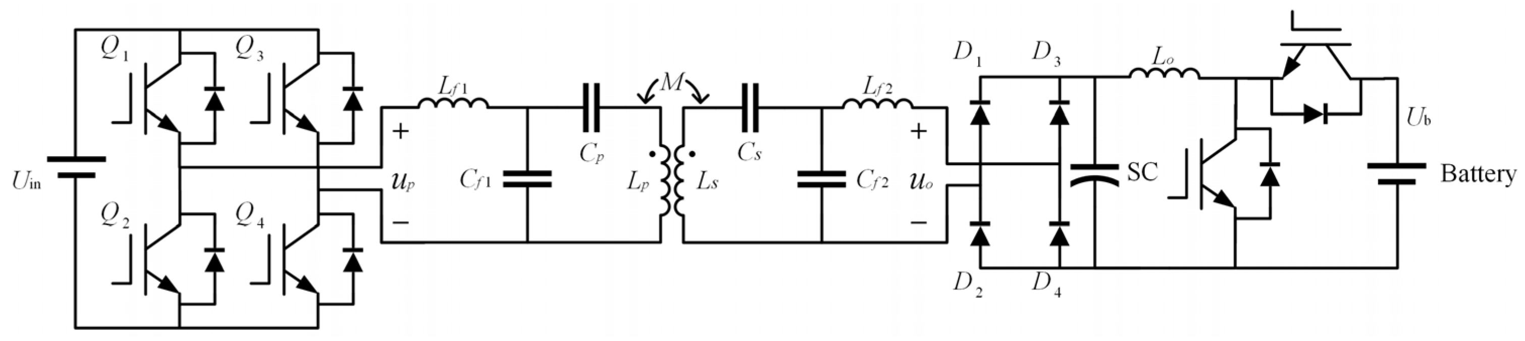
2. Working Principle of the Wireless Power Transfer System

The configuration of the LCCLCC compensation network and its associated power electronics components are depicted in Figure 1. On the primary side, Q1Q4 represent four power switches. They form a full-bridge inverter to provide AC excitation for the compensation network from the DC bus Uin. The self-inductance of the loosely coupled transformer is denoted as L1 and L2. The primary-side compensation comprises the inductor Lf1 and capacitors Cf1 and C1, while the secondary-side compensation includes the inductor Lf2 and capacitors Cf2 and C2. The mutual inductance between the two coils is represented by M. The secondary-side rectifier diodes are indicated as D1D4. Of note, the system model includes a HESS load, which consists of supercapacitors and batteries. A DC converter is employed to control the energy flow within the system.
By neglecting the losses in the circuit and treating the circuit after the rectifier as an integrated load, Req, we can derive a simplified WPT system, illustrated in Figure 2. The input voltage is referred to as up, and the output voltage before the rectifier is denoted as uo. The currents flowing through L1, L2, Lf1, and Lf2 are indicated by i1, i2, iLf1, and iLf2, respectively. Similarly, the voltages across C1, C2, Cf1, and Cf2 are indicated by uC1, uC2, uCf1 and uCf2.
The frequency characteristics of the LCCLCC network can be represented by state–space equations. By choosing capacitor voltages and inductor currents as state variables, a unified form of the state–space representation is derived:
d x ( t ) d t = Ax ( t ) + B u p ( t ) i L f 2 ( t ) = Cx ( t )
where x(t) denotes the state vector, input voltage up(t) is defined as the system input variable, the output current iLf2(t) is defined as the system output variable, and the state variables and the parameter matrices are defined as follows:
x = i L f 1 u C f 1 u C 1 i L 1 i L 2 u C 2 u C f 2 i L f 2 T
A = 1 L f 1 1 C f 1 1 C f 1 1 C 1 L 2 L k L 2 L k M L k M L k M L k M L k L 1 L k L 1 L k 1 C 2 1 C f 2 1 C f 2 1 L f 2 R e q L f 2
B = 1 L f 1 0 0 0 0 0 0 0 T
C = 0 0 0 0 0 0 0 1
where Lk is defined as follows:
L k = L 1 L 2 M 2
The characteristic equation of the system can thus be deduced as follows:
| s E 8 A | = 0
where E8 denotes the eight-order identity matrix. The Laplace form of Equation (1) can be derived as follows:
i Lf 2 s = Y s u p s Y s = C s E 8 A 1 B
Herein, Y(s) epitomizes the steady-state relationship between output iLf2 and input up.
As depicted in Figure 3, there are multiple resonant frequencies ω0, ω1, and ω2. However, in this study, we do not focus on the overall frequency-domain characteristics. The constant resonant frequency ω0 is determined under the following conditions:
L f 1 C f 1 = 1 ω 0 2 L f 2 C f 2 = 1 ω 0 2 L 1 L f 1 = 1 ω 0 2 C 1 L 2 L f 2 = 1 ω 0 2 C 2
The inverter generates a square voltage, up, across its output. At a constant resonant frequency, ω0, the fundamental voltage component can be considered approximately. Consequently, a phasor analysis of the WPT system is appropriate. In the subsequent analysis, the phasor forms of the system variables are represented by Up, Uo, I1, I2, ILf1, and ILf2. Taking the input voltage Up as the reference, we can proceed with the analysis as follows:
U p = U p 0 °
I 1 = U p j ω 0 L f 1
Based on mutual inductance coupling, the voltage induced in the secondary coil can be determined as follows:
U t r a n s = j ω 0 M 1 = M U p L f 1 0 °
When Utrans is applied in the secondary LCC circuit, the analysis is similar to that when Up is applied to the primary side. As a result, the output current can be determined using similar principles:
I L f 2 = U t r a n s j ω 0 L 2 + 1 j ω 0 C 2
After substituting Equations (9) and (12) into (13), the output current ILf2 can be obtained as follows:
I L f 2 = U t r a n s j ω 0 L f 2 = M U p ω 0 L f 1 L f 2 90 ° = I L f 2 90 °
Since the terminal voltage of the rectifier, Uo, must be in phase with ILf2, Uo is a passive voltage generated based on the load condition, as shown in Figure 4.
U o = U o 90 °
Based on Equations (13) and (14), the output power can be derived as follows:
P o = U o I L f 2 = M U p U o ω 0 L f 1 L f 2
According to Equation (16), the output power of the WPT system is related to the terminal voltage Uo. Moreover, Equation (14) shows that the LCCLCC compensation structure enables the system to operate in a constant current mode. Therefore, by adjusting Uo, the output power Po can be regulated effectively.

3. Analysis of the DC Converter

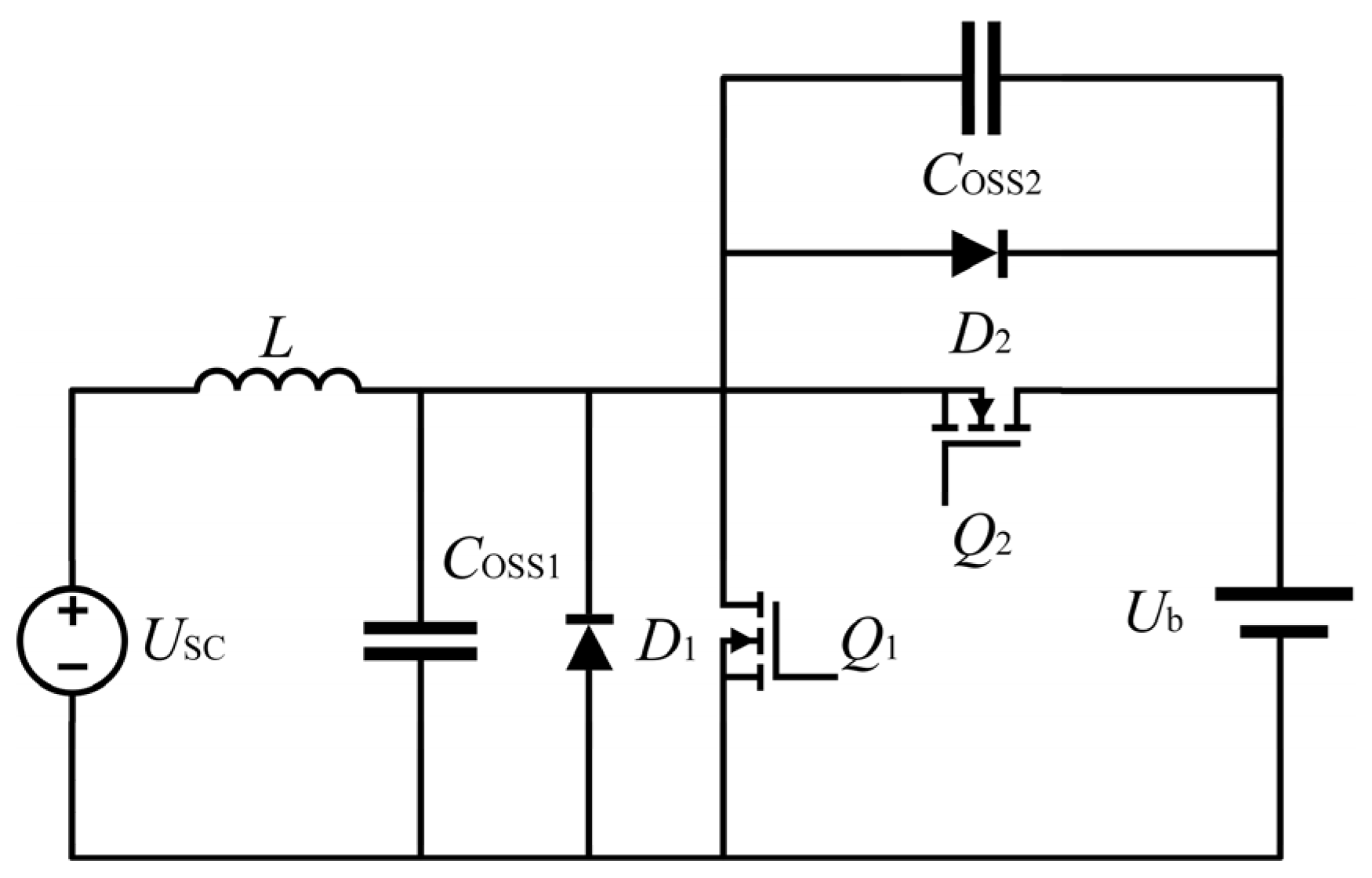
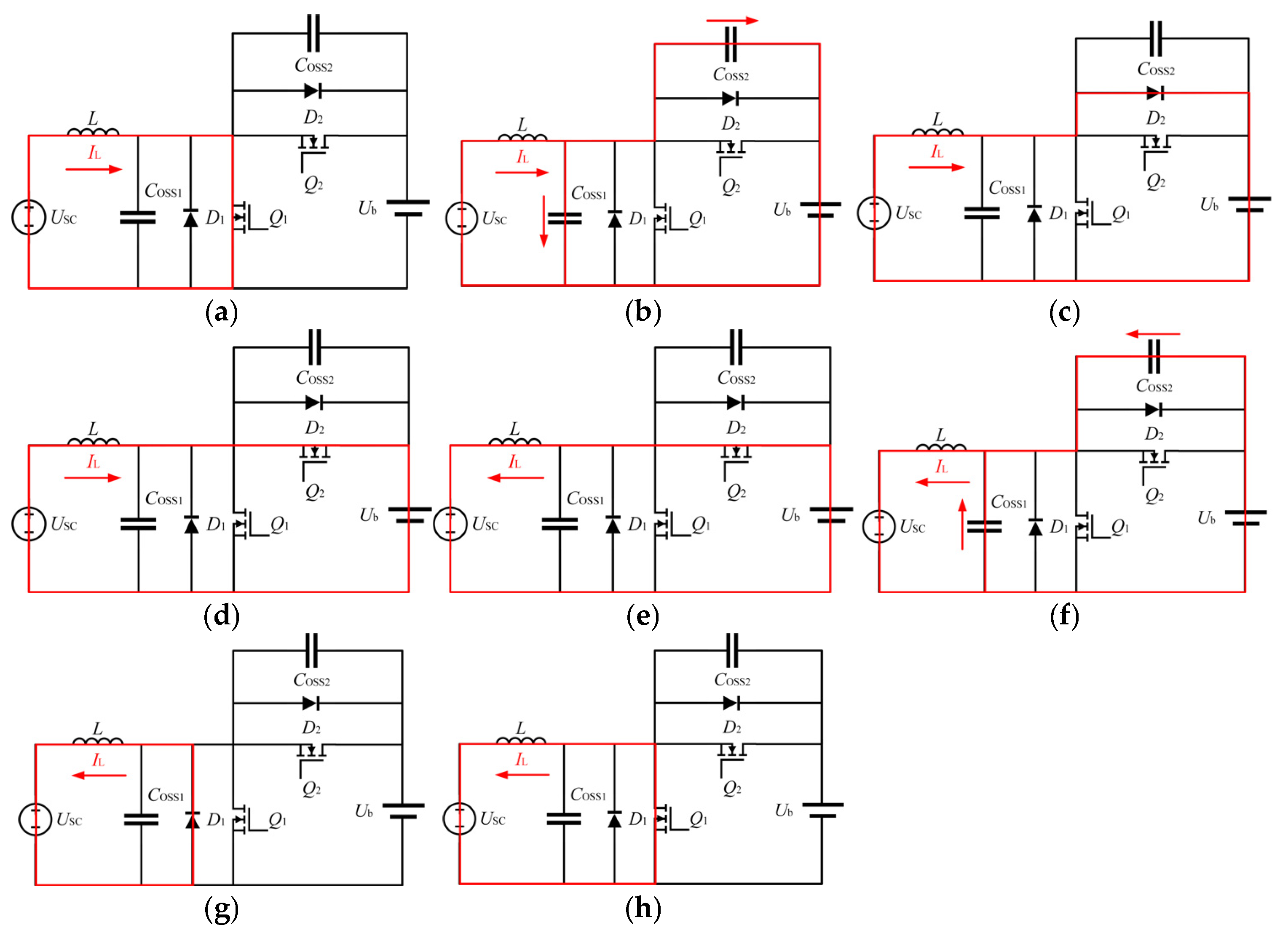
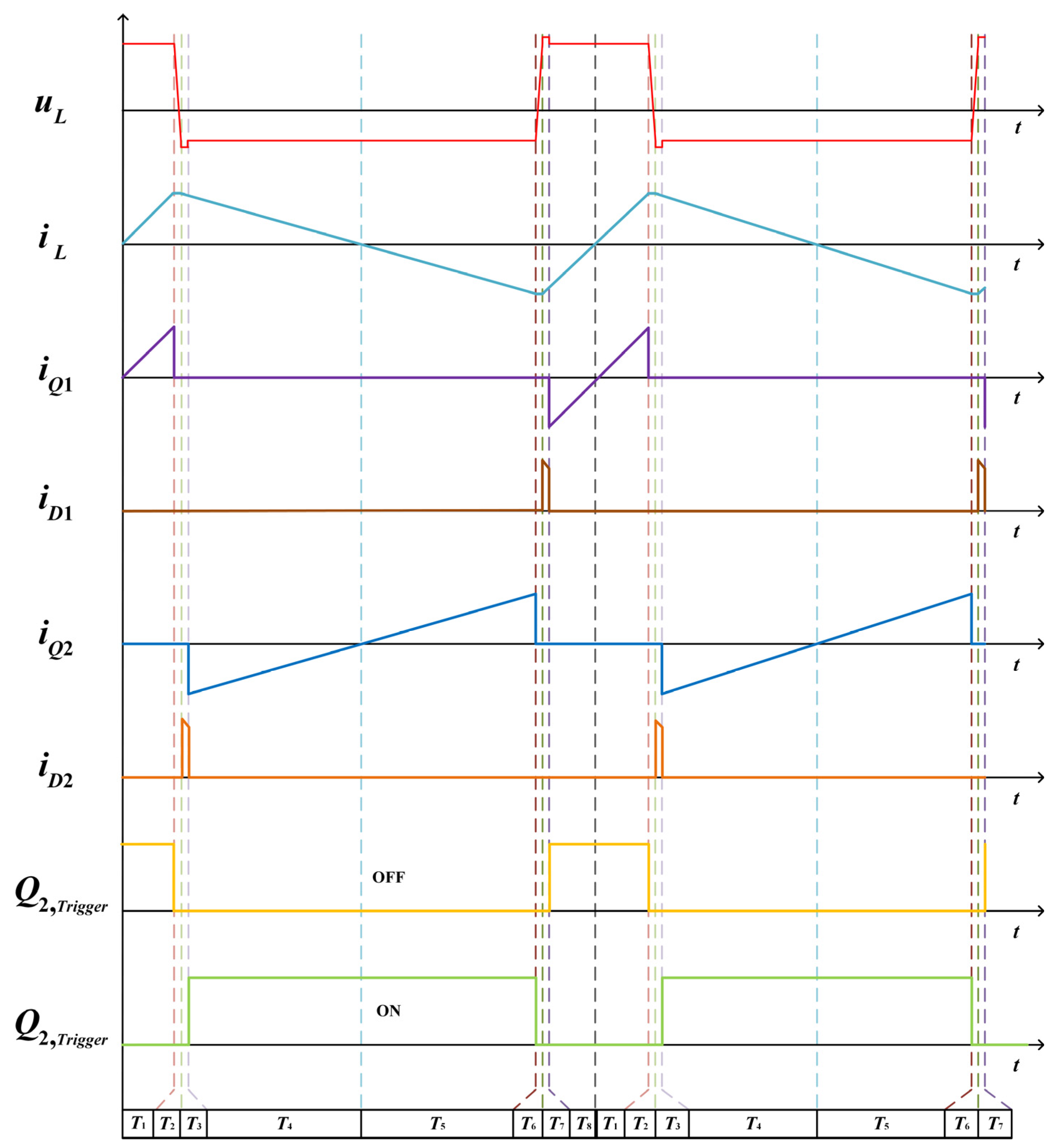
3.1. Operation of the DC Converter

As depicted in Figure 1, a DC converter between the supercapacitor and the battery can regulate Uo, thereby indirectly managing the system’s output power. Nevertheless, the inclusion of the converter adds an additional stage in the system, which diminishes the overall efficiency. To counteract this reduction in efficiency, this study proposes an efficient Buck/Boost converter operation mode to enhance efficiency. Figure 5 shows the Buck/Boost converter topology. In this configuration, USC denotes the port voltage across the supercapacitor, Ub denotes the battery port voltage, Q1 and Q2 are the switching devices, D1 and D2 are the anti-parallel diodes, L is the inductor, and Coss1 and Coss2 represent the drain-source capacitances of the switching devices. Lying on the low-voltage side, the supercapacitor enhances voltage utilization, reduces the voltage stress, and improves economic efficiency.
The conventional control strategy for the Buck/Boost bidirectional converter employs an independent PWM control strategy where switching devices Q1/D1 and Q2/D2 do not operate concurrently. Under this strategy, the circuit functions as a back-to-back configuration of Buck and Boost circuits. To maintain bidirectional power flow, a logic unit is essential for switching between operating states, typically utilizing hysteresis logic for smooth transitions. Conversely, in the complementary PWM control strategy, Q1/D1 and Q2/D2 operate concurrently, a method referred to as synchronous rectification. This mode allows the Buck/Boost bidirectional converter to achieve soft switching. Moreover, without a logic control unit, the system response is quick. In terms of rapid energy storage, the supercapacitor frequently absorbs and releases power, making it well suited for complementary PWM control.
In continuous current mode (CCM), diode conduction loss is significant, and the devices can only perform hard switching. In contrast, discontinuous current mode (DCM) allows for soft switching but still incurs diode conduction losses. The inductor current continues through the anti-parallel diode. When this current is substantial, conduction losses increase in the diode. In CCM, moreover, reverse recovery currents of the diode lead to additional losses.
To minimize working losses and achieve soft switching for the switching devices, the converter operates in synchronous PWM mode. The alternating conduction of Q1/D1 and Q2/D2 replaces the anti-parallel diode for current commutating. Since the MOSFET’s conduction loss is lower than that of the diode, the conduction losses are reduced. Moreover, by controlling the switching devices, the inductor current can flow bidirectionally in each cycle, forming an asymmetric bidirectional conduction mode. In this mode, the switching devices turn off while the current is still flowing, enabling the drain-source capacitance to charge and discharge effectively, thus achieving zero-voltage switching (ZVS) turn-off. Additionally, commutating by switching devices eliminates oscillations caused by the diode. By configuring the dead time, the switching devices perform brief conductance during the transition. This enables ZVS turn-on of the MOSFET after the dead time ends.
The operating states of the converter are illustrated in Figure 6. The circuit waveforms are depicted in Figure 7.
In a steady state, the initial condition is that Q1 is turned on while Q2 is off. At this moment, the circuit operates in Boost mode. Inductor L holds a positive voltage, and inductor current iL increases, as shown in Figure 6a. The waveform corresponds to time interval T1 in Figure 7. Next, Q1 is turned off, and iL continues to flow through D1, charging Coss1 and discharging Coss2. The circuit transitions into T2, as shown in Figure 6b. Due to the small drain-source capacitance and large inductance of L, T2 lasts for a very short duration with almost no change in the iL. After the dead time ends, Q2 is turned on, transitioning the circuit into T4, as shown in Figure 6d. Since D2 conducts first, no voltage crosses Q2 before it turns on, thus achieving ZVS. Consequently, the circuit operates in Buck mode.
In Buck mode, the current decreases as it passes through L until it reaches zero; then, it starts increasing in the opposite direction. The circuit transitions into T5, as illustrated in Figure 6e. Subsequently, Q2 turns off, and the circuit experiences a second dead time within the cycle. The circuit transitions into T6, as shown in Figure 6f. Until the voltage passing through Q1 drops to zero, Q1 naturally turns on. Due to the dead time, Q1 cannot turn on immediately. Period T7 is shown in Figure 6g. When Q1 turns on after the dead time, its anti-parallel diode, D1, conducts first, achieving ZVS, and the circuit transitions into Boost mode again. T8 is shown in Figure 6h. During operation, the circuit continuously cycles through these eight modes to achieve efficient operation.

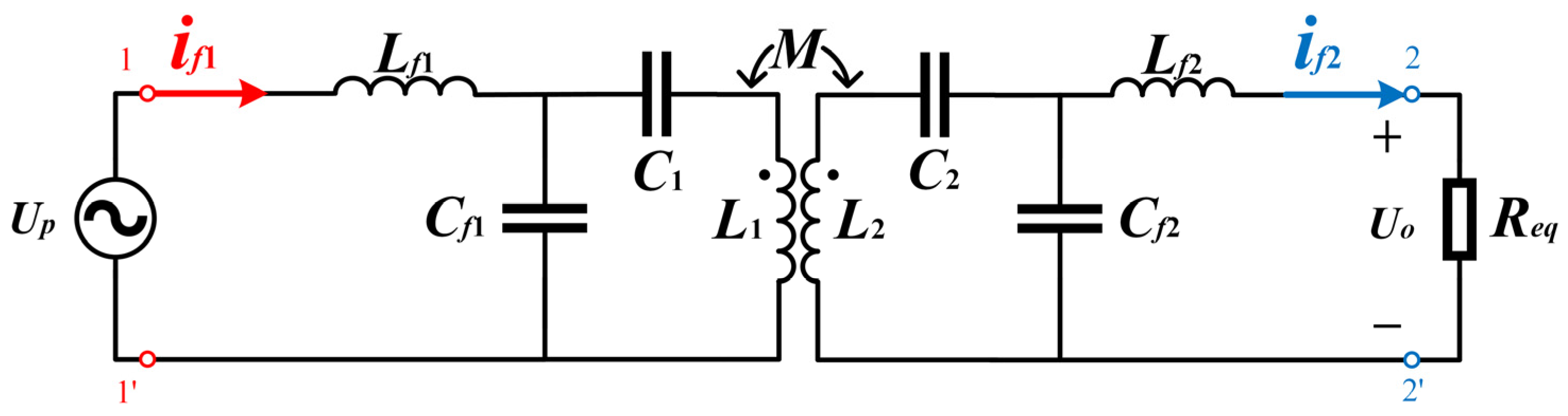
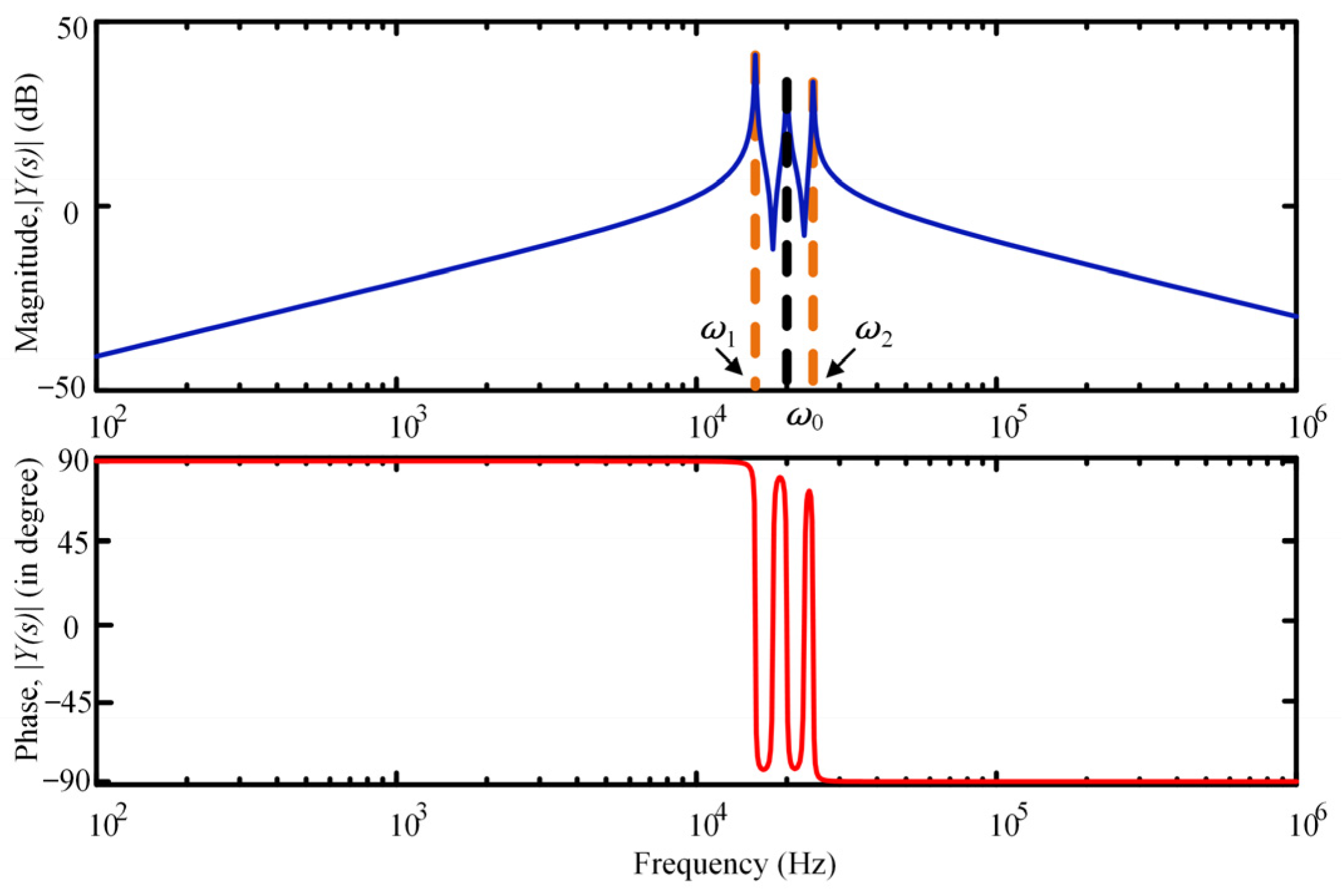
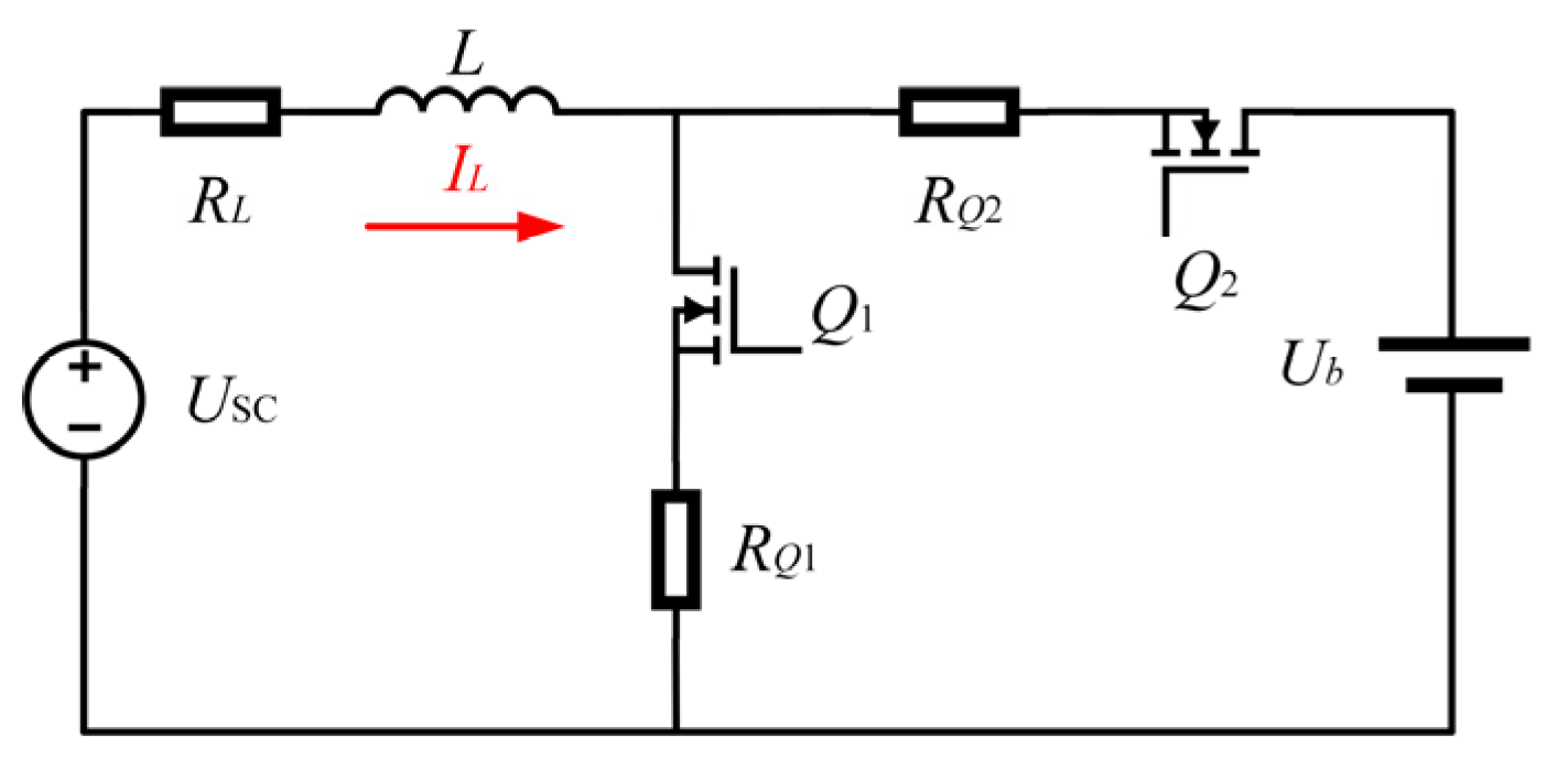
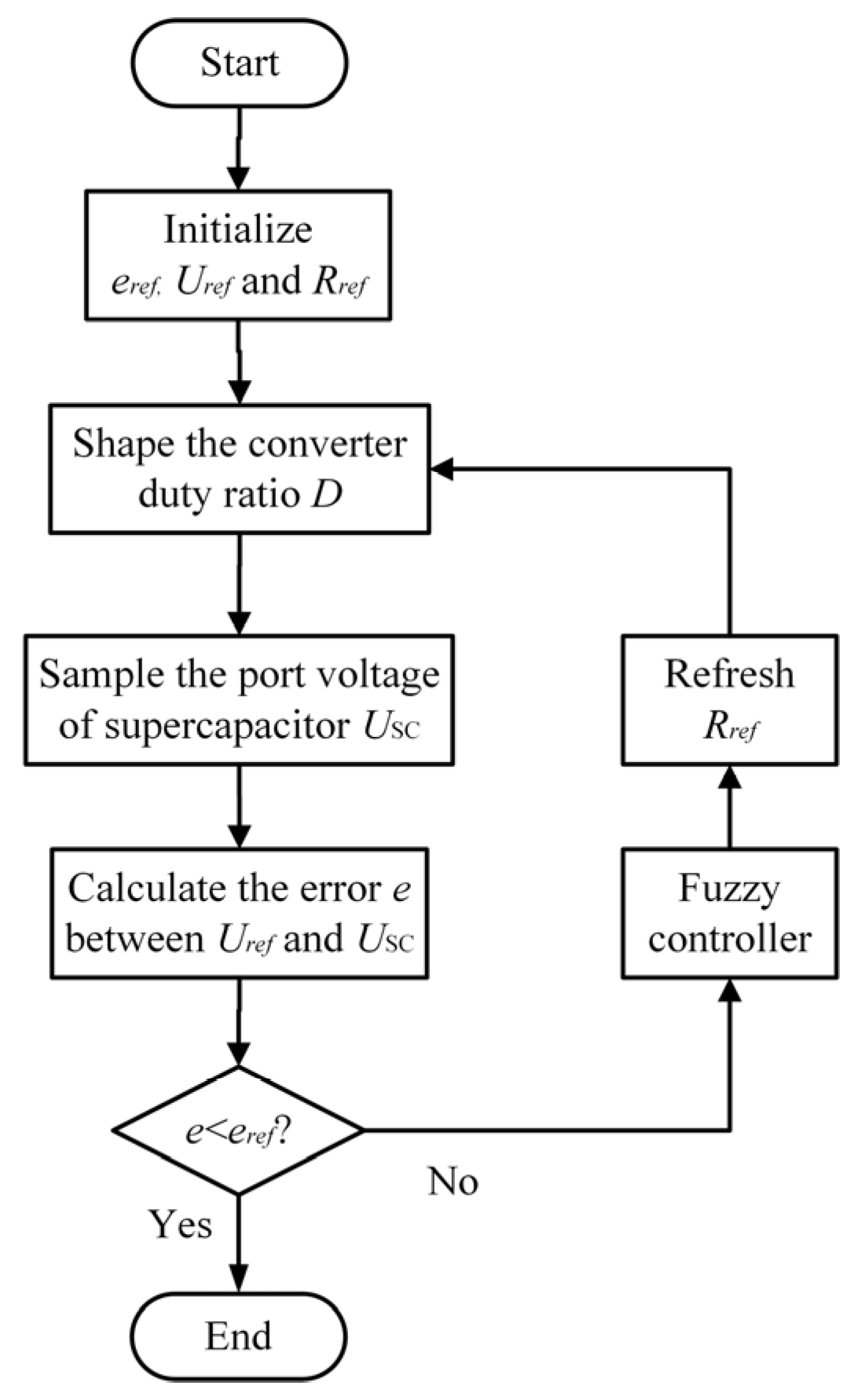
3.2. Circuit Analysis and Controller
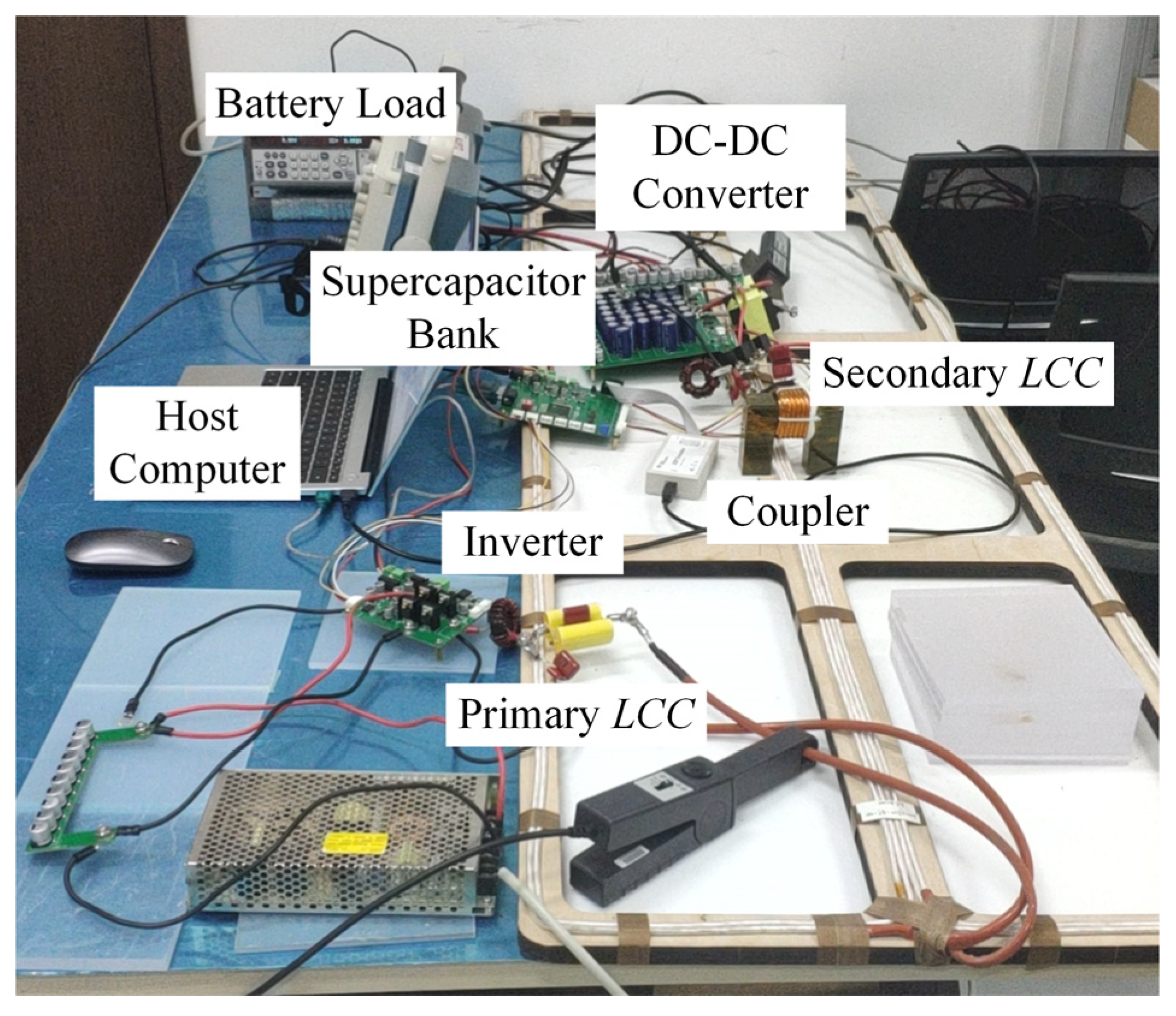
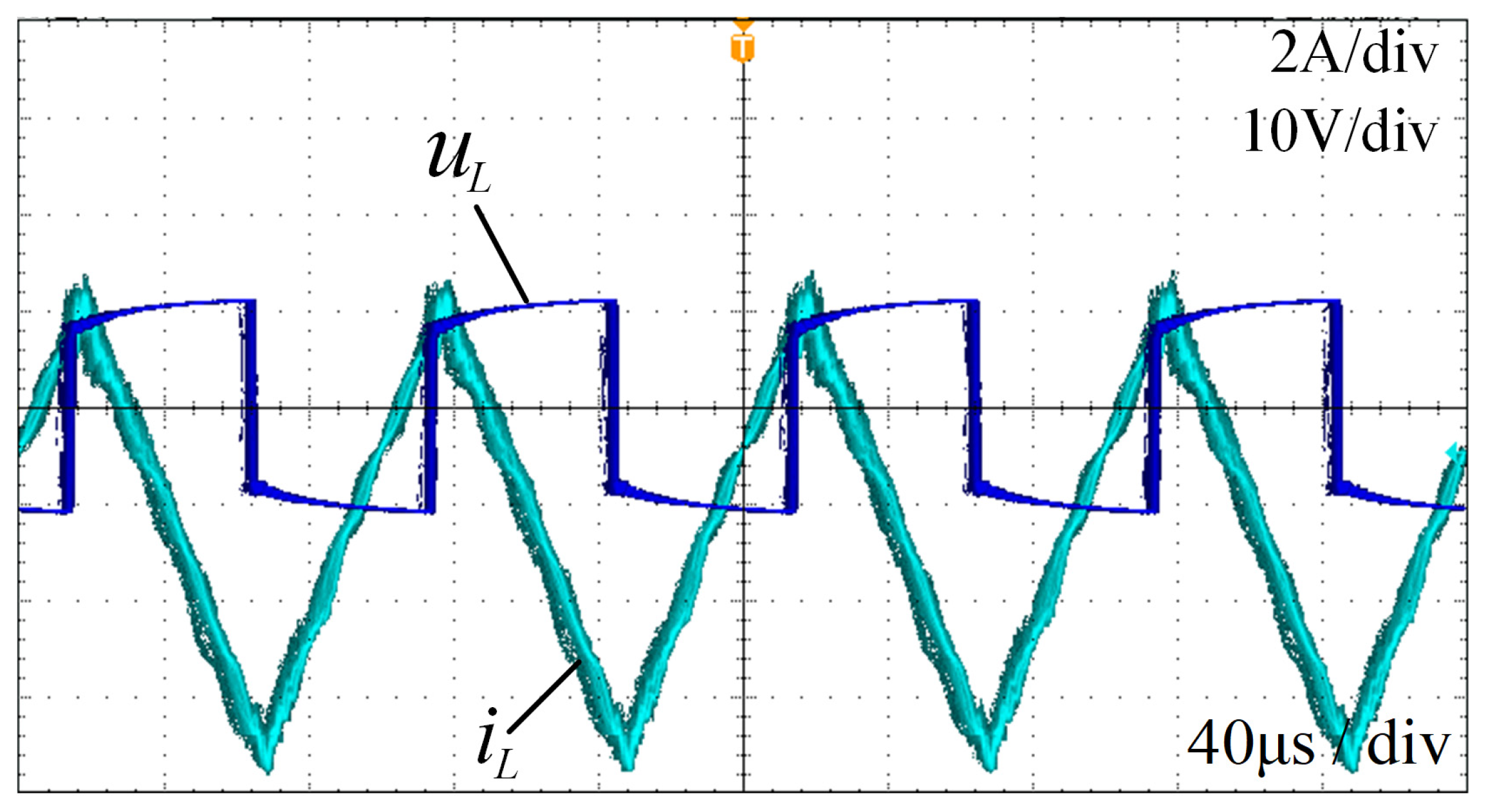
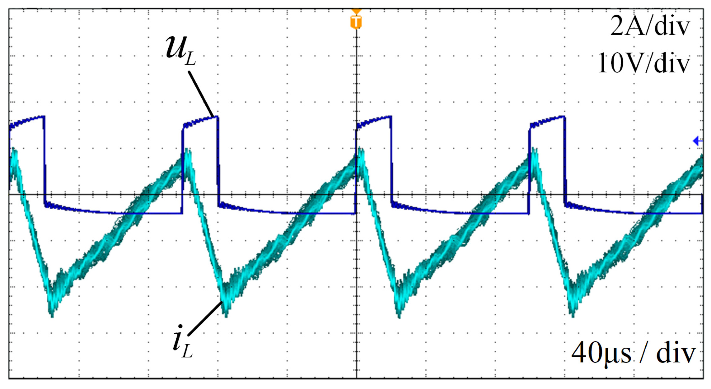
Based on the above analysis, when the Buck/Boost converter is in a steady state, the average inductor current over a period must satisfy the volt-second balance principle. Consequently, the duty cycle Dref can be derived as follows:
D r e f = 1 U SC U b
In control theory, it is necessary to change the reference value and wait for the converter to return to a steady state. This control strategy relies on the current loop, which demands high precision and fast response in current sampling and often neglects the equivalent series resistance (ESR) in the circuit. In practical circuits, the inductor possesses ESR, and the switching devices have conduction resistance, which should be considered in the control strategy. Additionally, under the complementary PWM control strategy, the conduction time of the diodes and the charging and discharging times of Coss1 and Coss2 are relatively short and can be neglected. Consequently, the Buck/Boost bidirectional converter circuit topology considering the resistance parameters is shown in Figure 8.
The following analysis is conducted on the circuit model in Figure 8. As the converter switches between the Boost and Buck modes, the positive direction is defined as shown in Figure 8. The expressions for iL can be derived as shown in Equations (18) and (19).
L d i L ( t ) Boost d t = U SC ( R L + R Q 1 ) i L ( t ) Boost
L d i L ( t ) Buck d t = U SC U b ( R L + R Q 2 ) i L ( t ) Buck
Assuming that the on-state resistances of Q1 and Q2 are equal, we can obtain that RQ = RQ1 = RQ2. Thus, Equation (20) can be derived, where D represents the duty cycle of Q1.
T T + D T L d i L ( t ) d t d t = T T + D T L d i L ( t ) Boost d t d t + T + D T 2 T L d i L ( t ) Buck d t d t     = U SC T U b ( T D T ) ( R L + R Q ) T 2 T i L ( t ) d t = 0
Thus, steady-state duty cycle D is as follows:
D = ( R L + R Q ) U b 1 T T 2 T i L ( t ) d t + 1 U SC U b = ( R L + R Q ) U b I L , avg + 1 U SC U b
Considering resistance in the circuit, duty cycle D is no longer solely dependent on USC and Ub. It is also influenced by the periodic average value of the inductor current IL,avg.
From Equation (21), the following can be derived:
I L , avg = U b D U b + U SC R L + R Q
Thus, the output power of the converter can be obtained as follows:
P c o n v = U SC I L , avg = U SC U b D U b + U SC R L + R Q
where Rref represents the sum of RL and RQ, and Rt represents the actual value of the sum of RL and RQ. Since Rref is a reference and Rt is difficult to measure accurately, any discrepancy between them will inevitably affect the operation of the converter. According to Equation (22), when Rref is given, the expected average inductor current Iref can be determined. IL,AVG represents the average inductor current based on a real circuit. The relationship between them is shown in Equation (24), which leads to Equation (25), where Pconv denotes the actual transmitted power, and Pref denotes the reference:
I L , A V G I r e f = U b D U b + U SC R t U b D U b + U SC R r e f = R r e f R t
P c o n v P r e f = U SC I L , A V G U SC I r e f = R r e f R t
Taking Rref as the control variable, the transmission power of the converter can be controlled. Based on this, a power control strategy for a bidirectional Buck/Boost converter using resistance parameters is proposed. According to Equations (22)–(25), we obtained the following:
D = 2 L U b 2 L U SC 2 L U b R r e f T U SC R t < R r e f < R t
P c o n v = R r e f T U SC 2 ( U b U SC ) R t ( 2 L U b R r e f T U SC ) R t < R r e f < R t
Based on the analysis of the bidirectional Buck/Boost converter, a control strategy is proposed. In a HESS, the presence of supercapacitors introduces a large time constant to the system. This characteristic poses significant challenges for traditional control methods, as determining precise control parameters for such plants becomes difficult. Conventional control strategies often struggle with the high-order system modeling accuracy required for effective control, leading to suboptimal performance. Fuzzy control, on the other hand, offers a robust solution by converting system uncertainties and fuzziness into fuzzy sets and utilizing fuzzy rules for inference and decision-making. This approach enables effective control of the system without the need for precise mathematical modeling, which is particularly advantageous for high-order systems where traditional methods fall short. By integrating fuzzy control into the LCC topology of a HESS in WPT applications, we can significantly enhance the overall system performance and converter efficiency. Fuzzy control’s ability to handle nonlinearities and uncertainties makes it an ideal choice for managing the complex dynamics of HESS systems. The fuzzy controller can dynamically adjust control parameters based on real-time system conditions, ensuring optimal performance even in the presence of variations and disturbances. The implementation of fuzzy control in the LCC topology provides a promising solution to optimize converter efficiency and improve system performance. It effectively addresses the control challenges posed by the large time constants and high-order dynamics inherent in HESS systems. In summary, the necessity of fuzzy control in HESS systems lies in its ability to transform uncertainties into manageable control actions, thereby overcoming the limitations of traditional control methods. This integration not only optimizes converter efficiency but also enhances the robustness and adaptability of the overall system, making it a crucial component for advanced WPT applications. The corresponding control flow diagram is shown in Figure 9. Finally, considering the instability and uncertainty of the WPT system, an intelligent control method, a fuzzy controller, is selected.
The fuzzy control rules used in this paper are shown in Figure 10. Here, e represents the error with respect to the reference value; de represents the rate of change in the error; and the output is the variation in Rref, ∆R. The fuzzy inference is based on the Mamdani method, and the defuzzification is based on the centroid method. The fuzzy rules are listed in Table 1.

4. Experiments

A prototype of the LCCLCC-compensated WPT system with a HESS load has been implemented in this experiment. As shown in Figure 11, the experiment platform comprises a host computer, a programmable DC power supply, a high-frequency inverter, LCCLCC compensation circuits, a magnetic coupler, a rectifier bridge, a Buck/Boost converter, and a DC electronic load acting as a battery. The programmable DC power supply and the full-bridge inverter generate a fixed-magnitude square wave at the resonant frequency to power the entire system. Control signals are generated by a TI-TMS320F28335 core control chip. This experiment utilizes the MATLAB ver. R2021a Embedded Coder for Hardware-in-the-Loop (HIL) experiments. To achieve better performance, the parameter configuration of the double-sided LCC compensation network follows the methodology outlined in [32]. The experimental parameters are shown in Table 2, where L represents the DC inductance, and CSC represents the total capacitance of the supercapacitor bank.
First, the voltage of the supercapacitor bank was charged to 12 V through the soft-start circuit. The waveforms of UL and IL once the steady state was reached are shown in Figure 12. The inductor current IL reached zero twice within a cycle, indicating that the Buck/Boost bidirectional converter operated in the designed mode. The DC converter steadily transferred power to the DC bus. When the port voltage was stabilized at 12 V, the output current was approximately 2.34 A, and the power output to the Buck/Boost bidirectional converter was 28.1 W. For the battery load, the electronic load received a current of 1.16 A and obtained a power of 27.8 W. Thus, the power transmission efficiency in the DC/DC stage was 98.9%.
Subsequently, the air gap of the electromagnetic coupler increased, resulting in a reduction in coupling inductance. The waveforms of UL and IL after the adjustment are shown in Figure 13. As seen from the waveform of IL, the Buck/Boost bidirectional converter consistently maintained operation in the critical mode. The supercapacitor bank charged the battery with maximum power. The output current was 1.62 A; the port voltage of the supercapacitor is 19 V; the supercapacitor bank provides an input power of 30.8 W to the converter; the battery load receives a current of 1.27 A from the converter; and the output power of converter is 30.5 W, resulting in a transmission efficiency of 99.0%.
Finally, the air gap decreased. The waveforms of UL and IL are shown in Figure 14. The output current decreased to 2.15 A, and the converter consistently operated in critical mode. At this time, the supercapacitor bank provided an output power of 40.9 W to the converter. The current flowing into the battery load was 1.69 A, with a charging power of 40.6 W. The transmission efficiency in a DC/DC stage was 99.3%.

5. Conclusions

This paper has investigated the suitability of HESS loads for WPT systems. A topology for the HESS load is derived, and the compensation performance is analyzed. It has been shown that the output characteristics of the LCCLCC topology built-in view of the HESS load are flexible. With the aid of supercapacitors and a DC converter, the output power of the WPT system can be easily controlled. We expect the total efficiency to remain largely unaffected by the converter. Additionally, the control of the converter needs to meet the system’s requirements. Therefore, an efficient operation mode for the converter is proposed, which generally exhibits lower switching losses and conduction losses. Consequently, the overall system efficiency is improved as the influence of the converter decreases. Besides, the operation principle of the converter is studied, and a fuzzy controller is implemented to achieve high robustness and handle the large time constant of the supercapacitor bank. Analysis and experimental results show that the proposed system can easily control the output power while maintaining high efficiency. While the results are promising, several specific challenges need to be addressed to fully realize the potential of this system in practical EV applications. One significant challenge is the real-time implementation of fuzzy control algorithms in hardware, ensuring that they can operate efficiently under varying conditions. Furthermore, the development of standardized protocols for communication and control in large-scale WPT networks is essential to ensure interoperability and seamless operation.

Author Contributions

Conceptualization, C.Y.; methodology, C.Y.; validation, C.Y., L.Z. and S.X.; formal analysis, C.Y.; resources, C.Y.; writing—original draft preparation, C.Y.; writing—review and editing, C.Y.; visualization, C.Y.; supervision, S.X. and L.Z.; project administration, L.Z. All authors have read and agreed to the published version of the manuscript.

Funding

This research received no external funding.

Institutional Review Board Statement

Not applicable.

Data Availability Statement

The original contributions presented in this study are included in the article. Further inquiries can be directed to the corresponding author.

Conflicts of Interest

The authors declare no conflicts of interest.

References

  1. Zhu, L.; Wang, L.; Wu, M.; Zhao, C.; Yu, L. Precise Modeling and Design of Self-Resonant for High-Efficiency Mid-Range Wireless Power Transfer System. IEEE Trans. Power Electr. 2023, 38, 7848–7862. [Google Scholar] [CrossRef]
  2. Chen, Y.; Niu, W.; Yang, Y.; Amirat, Y. Experimental Results and Analysis of Midrange Underwater Asymmetric Wireless Power Transfer. J. Mar. Sci. Eng. 2024, 12, 567. [Google Scholar] [CrossRef]
  3. Ma, Y.; Liang, B.; Wang, J.; Cheng, B.; Yan, Z.; Dong, M.; Mao, Z. A Novel Hill Climbing-Golden Section Search Maximum Energy Efficiency Tracking Method for Wireless Power Transfer Systems in Unmanned Underwater Vehicles. J. Mar. Sci. Eng. 2024, 12, 1336. [Google Scholar] [CrossRef]
  4. Feng, H.; Tavakoli, R.; Onar, O.C.; Pantic, Z. Advances in High-Power Wireless Charging Systems: Overview and Design Considerations. IEEE Trans. Transp. Electr. 2020, 6, 886–919. [Google Scholar] [CrossRef]
  5. Liu, C.; Jiang, C.; Song, J.; Chau, K.T. An Effective Sandwiched Wireless Power Transfer System for Charging Implantable Cardiac Pacemaker. IEEE Trans. Ind. Electron. 2019, 66, 4108–4117. [Google Scholar] [CrossRef]
  6. Moore, J.; Castellanos, S.; Xu, S.; Wood, B.; Ren, H.; Tse, Z.T.H. Applications of Wireless Power Transfer in Medicine: State-of-the-Art Reviews. Ann. Biomed. Eng. 2019, 47, 22–38. [Google Scholar] [CrossRef]
  7. Patil, D.; McDonough, M.K.; Miller, J.M.; Fahimi, B.; Balsara, P.T. Wireless Power Transfer for Vehicular Applications: Overview and Challenges. IEEE Trans. Transp. Electr. 2018, 4, 3–37. [Google Scholar] [CrossRef]
  8. Li, K.; Liu, Y.; Sun, X.; Tian, X.; Lei, G. Applications of Wireless Power Transfer System in Motors: A Review. IEEE Access 2024, 12, 80590–80606. [Google Scholar] [CrossRef]
  9. Sun, L.; Ma, D.; Tang, H. A review of recent trends in wireless power transfer technology and its applications in electric vehicle wireless charging. Renew. Sustain. Energy Rev. 2018, 91, 490–503. [Google Scholar] [CrossRef]
  10. Fan, M.; Shi, L.; Yin, Z.; Jiang, L.; Zhang, F. Improved Pulse Density Modulation for Semi-bridgeless Active Rectifier in Inductive Power Transfer System. IEEE Trans. Power Electr. 2019, 34, 5893–5902. [Google Scholar] [CrossRef]
  11. Chen, S.; Zeng, J.; Tang, Y. A Super-Resonant Frequency Control for Handshaking of an Inductive Power Transfer System with Adjacent Units. IEEE Trans. Ind. Electron. 2024, 71, 1073–1076. [Google Scholar] [CrossRef]
  12. Huang, J.; He, X.; Huo, P.; Xu, R. A Hybrid Modulation Strategy for LCCLCC Compensated Bidirectional Wireless Power Transfer System to Achieve High Efficiency in the Whole Operating Range. IEEE Trans. Ind. Electron. 2024, 71, 327–337. [Google Scholar] [CrossRef]
  13. Luo, B.; Long, T.; Guo, L.; Dai, R.; Mai, R.; He, Z. Analysis and Design of Inductive and Capacitive Hybrid Wireless Power Transfer System for Railway Application. IEEE Trans. Ind. Appl. 2020, 56, 3034–3042. [Google Scholar] [CrossRef]
  14. Tan, T.; Chen, K.; Lin, Q.; Jiang, Y.; Yuan, L.; Zhao, Z. Impedance Shaping Control Strategy for Wireless Power Transfer System Based on Dynamic Small-Signal Analysis. IEEE Trans. Circuits Syst. I Regul. Pap. 2021, 68, 1354–1365. [Google Scholar] [CrossRef]
  15. Song, K.; Lan, Y.; Zhang, X.; Jiang, J.; Sun, C.; Yang, G.; Yang, F.; Lan, H. A Review on Interoperability of Wireless Charging Systems for Electric Vehicles. Energies 2023, 16, 1653. [Google Scholar] [CrossRef]
  16. Lan, Y.; Jiang, J.; Yang, F.; Song, K.; Fan, F.; Sun, C.; Yang, G.; Zhang, B.; Lan, H. Research on Impedance Boundary and Tolerance Zone for Improving Wireless Charging Interoperability Evaluation of Electric Vehicles. IEEE Trans. Power Electr. 2024, 39, 12035–12040. [Google Scholar] [CrossRef]
  17. Chang, X.; Huang, L.; Zhang, X.; Yang, J.; Liu, H. Study on the Dynamic Optimal Control Strategy of an Electric-Hydrogen Hybrid Energy Storage System for a Direct Drive Wave Power Generation System. J. Mar. Sci. Eng. 2023, 11, 1347. [Google Scholar] [CrossRef]
  18. Saeed, M.; Briz, F.; Guerrero, J.M.; Larrazabal, I.; Ortega, D.; Lopez, V.; Valera, J.J. Onboard Energy Storage Systems for Railway: Present and Trends. IEEE Open J. Ind. Appl. 2023, 4, 238–259. [Google Scholar] [CrossRef]
  19. Zhao, J.; Li, L.; Wu, H.; Luo, B.; Li, H.; Zhang, Y.; Liu, S.; Zhao, L. An Optimized Multi-Level Control Method for Wireless Power Transfer System Using the Particle Swarm Optimization Algorithm. Electronics 2024, 13, 4341. [Google Scholar] [CrossRef]
  20. Gao, P.; Li, Y.; Yao, W.; Zheng, X.; Zhang, C. Optimization of Hybrid Energy Storage System Sizing with Considering Energy Management Strategy for High-Power Pulsed Load in Aircraft. IEEE Trans. Veh. Technol. 2023, 72, 4525–4537. [Google Scholar] [CrossRef]
  21. Shevchenko, V.; Husev, O.; Strzelecki, R.; Pakhaliuk, B.; Poliakov, N.; Strzelecka, N. Compensation Topologies in IPT Systems: Standards, Requirements, Classification, Analysis, Comparison and Application. IEEE Access 2019, 7, 120559–120580. [Google Scholar] [CrossRef]
  22. Iam, I.; Choi, C.; Lam, C.; Mak, P.; Martins, R.P. A Constant-Power and Optimal-Transfer-Efficiency Wireless Inductive Power Transfer Converter for Battery Charger. IEEE Trans. Ind. Electron. 2024, 71, 450–461. [Google Scholar] [CrossRef]
  23. Lu, Y.; Ge, D.; Meng, L.; Sun, C.; Tang, Q.; Gao, Y.; Chen, M.; Xia, C. A Novel Optimization Method of Compensation Network Parameters for LCC Topology Wireless Power Transfer System with Anti-Offset Characteristics. IEEE Access 2024, 12, 5960–5972. [Google Scholar] [CrossRef]
  24. Xiong, M.; Dai, H.; Li, Q.; Jiang, Z.; Luo, Z.; Wei, X. Design of theLCC -SP Topology with a Current Doubler for 11-kW Wireless Charging System of Electric Vehicles. IEEE Trans. Transp. Electr. 2021, 7, 2128–2142. [Google Scholar] [CrossRef]
  25. Hou, X.; Hu, H.; Su, Y.; Liu, Z.; Deng, Z.; Deng, R. A Multirelay Wireless Power Transfer System with Double-Sided LCC Compensation Network for Online Monitoring Equipment. IEEE J. Emerg. Sel. Top. Power Electron. 2023, 11, 1262–1271. [Google Scholar] [CrossRef]
  26. Wang, F.; Zhang, W.; Ye, L.; Guo, J.; Liu, K.; Do, H.T. A Design Method to Implement ZVS for Electric Vehicle Wireless Charging System with Double-Side LCC Compensation. IEEE J. Emerg. Sel. Top. Power Electron. 2021, 9, 3791–3801. [Google Scholar] [CrossRef]
  27. Zhong, W.X.; Hui, S.Y.R. Maximum Energy Efficiency Tracking for Wireless Power Transfer Systems. IEEE Trans. Power Electr. 2015, 30, 4025–4034. [Google Scholar] [CrossRef]
  28. Wu, H.H.; Gilchrist, A.; Sealy, K.D.; Bronson, D. A High Efficiency 5 kW Inductive Charger for EVs Using Dual Side Control. IEEE Trans. Ind. Inf. Inform. 2012, 8, 585–595. [Google Scholar] [CrossRef]
  29. Wang, L.J.; Gonder, J.; Burton, E.; Brooker, A.; Meintz, A.; Konan, A. IEEE A Cost Effectiveness Analysis of Quasi-Static Wireless Power Transfer for Plug-In Hybrid Electric Transit Buses. In Proceedings of the 2015 12th IEEE Vehicle Power and Propulsion Conference (VPPC), Montreal, QC, Canada, 19–22 October 2015. [Google Scholar]
  30. Hata, K.; Huang, X.L.; Hori, Y. IEEE Power Flow Control of Magnetic Resonance Wireless Charing for Hybrid Energy Storage System of Electric Vehicles Application. In Proceedings of the 2015 54th Annual Conference of the Society of Instrument and Control Engineers of Japan (SICE), Hangzhou, China, 28–30 July 2015; pp. 1459–1462. [Google Scholar]
  31. Geng, Y.Y.; Li, B.; Yang, Z.P.; Lin, F.; Sun, H. A High Efficiency Charging Strategy for a Supercapacitor Using a Wireless Power Transfer System Based on Inductor/Capacitor/Capacitor (LCC) Compensation Topology. Energies 2017, 10, 135. [Google Scholar] [CrossRef]
  32. Nguyen, V.; Vu, V.; Gohil, G.; Fahimi, B. Coil-to-Coil Efficiency Optimization of Double-Sided LCC Topology for Electric Vehicle Inductive Chargers. IEEE Trans. Ind. Electron. 2022, 69, 11242–11252. [Google Scholar] [CrossRef]
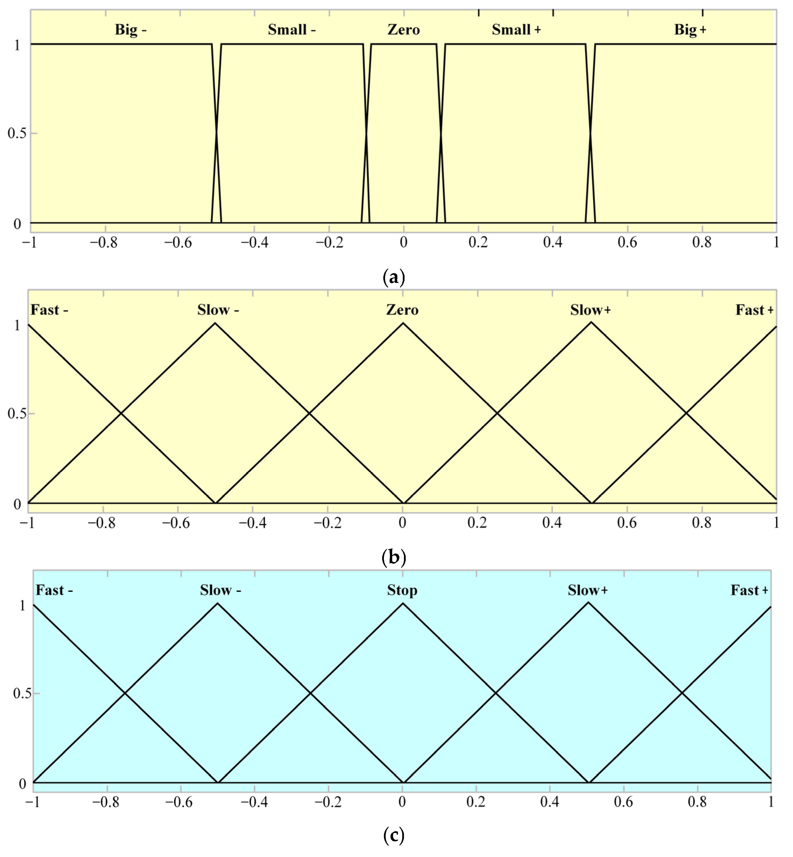
Figure 1. Schematic diagram of a WPT system with a HESS load.
Sustainability 17 02358 g001
Figure 2. Equivalent circuit of an LCCLCC-compensated WPT system.
Sustainability 17 02358 g002
Figure 3. Frequency characteristics of the LCCLCC network.
Sustainability 17 02358 g003
Figure 4. Equivalent circuit of LCCLCC topology.
Sustainability 17 02358 g004
Figure 5. Equivalent circuit of Buck/Boost converter.
Sustainability 17 02358 g005
Figure 6. The operating states of the Buck/Boost converter during the time intervals (a) T1, (b) T2, (c) T3, (d) T4, (e) T5, (f) T6, (g) T7 and (h) T8.
Sustainability 17 02358 g006
Figure 7. The waveforms of Buck/Boost converter.
Sustainability 17 02358 g007
Figure 8. Equivalent circuit of Buck/Boost converter with resistance parameters.
Sustainability 17 02358 g008
Figure 9. Control flow diagram of the Buck/Boost converter.
Sustainability 17 02358 g009
Figure 10. The fuzzy control rules of (a) e, (b) de, and (c) ∆R.
Sustainability 17 02358 g010
Figure 11. Experimental platform.
Sustainability 17 02358 g011
Figure 12. Waveforms of UL and IL when USC is 12 V and the air gap is small.
Sustainability 17 02358 g012
Figure 13. Waveforms of UL and IL when USC is 19 V and the air gap is large.
Sustainability 17 02358 g013
Figure 14. Waveforms of UL and IL when USC is 19 V and the air gap decreased.
Sustainability 17 02358 g014
Table 1. Fuzzy control rules.
eBig−Small−ZeroSmall+Big+
RFast+Slow+StopSlow−Big−
Table 2. Parameters of the experiment platform.
ParameterValueParameterValue
Uin/V15Ub/V24
Lf1/μH35CSC/F3
Cf1/μF7.2L/μH60
C1/μF50.7C2/μF5.1
L1/μH40.07Cf2/μF16.9
L2/μH65.22Lf2/μH15
Uin/V15Ub/V24
Disclaimer/Publisher’s Note: The statements, opinions and data contained in all publications are solely those of the individual author(s) and contributor(s) and not of MDPI and/or the editor(s). MDPI and/or the editor(s) disclaim responsibility for any injury to people or property resulting from any ideas, methods, instructions or products referred to in the content.

