Article

Lightweight Aggregates with Special Microstructure for Use in Rooftop Garden Design

by
Agata Stempkowska
Department of Environmental Engineering, Faculty of Civil Engineering and Resource Management, AGH University of Kraków, Mickiewicza 30 Av., 30-059 Kraków, Poland
Sustainability 2025, 17(21), 9489; https://doi.org/10.3390/su17219489 (registering DOI)
Submission received: 1 September 2025 / Revised: 12 October 2025 / Accepted: 14 October 2025 / Published: 24 October 2025
(This article belongs to the Topic Sustainable Building Materials)

Abstract

Continuous urban land development is causing environmental changes. The most visible effects are a decline in biodiversity, an increase in urban temperatures, and changes in the water balance. Recently, very intense and sudden rainfall events have been observed, and existing drainage systems are not effective enough. Urban surfaces tend to be impermeable with low retention, so there is no way to respond to both the rainy periods and the drought periods that often follow. A good remedy for these factors is urban greening, which can be achieved through the design of green roofs and living walls. The substrate used for this type of construction should be light, permeable, and retentive. This study aimed to produce artificial aggregate granules with various additives that modify the structure to create open mesopores and facilitate better rainwater management. Through suitable sintering, materials with water absorption of more than 40%, retention in simulated rainfall of over 35% and a bulk density of ~0.70 g/cm3 were obtained. Detailed microstructural analyses were carried out using various microscopic techniques. Strength tests and simple vegetation tests were also carried out.

1. Introduction

Living in a city involves many privileges, which is why more and more people around the world are choosing to move to urban areas. Agglomerations and urban spaces are spreading across ever larger areas, with environmental consequences. These can include a reduction in species diversity, increased air pollution, higher temperatures, the creation of locally distinct microclimates, and changes in the water balance. A green city is a modern city that, through technology and the use of numerous architectural and constructional solutions, acquires a different dimension of living space. However, in densely populated areas, it is not possible to replant a forest or sow a flower bed. Therefore, green roofs and living walls are the solution. Many cities around the world have already implemented regulations and incentives for the creation of such facilities. The tradition of rooftop gardens in the Middle East has been known since antiquity [1,2], while the design of green roofs has flourished in modern times in Europe [3,4,5]. Asian and North American countries began to promote urban greening in the early 21st century [6,7,8,9,10]. The degree of urban greening is constantly increasing and, for example, in Tokyo (Japan), newly constructed buildings are required to have 25% of their roofs covered with vegetation [11]. Public opinion is generally friendly towards the installation of green roofs; after all, no one wants to live in a concrete desert. However, there are perceived problems with the high cost of installing and maintaining such projects [12,13].
A green roof is a linear composite structure. This structure can be divided into the following properties: drainage layer, filtration layer, substrate layer, and vegetation layer [14,15]. The properties of the substrate layers and vegetation affect the functionality of the green roof. Therefore, these layers can be considered the most important. They are also a criterion for dividing these roofs into intensive and extensive [16,17,18,19]. An extensive roof is covered with a layer of plants that do not require intensive maintenance. It is lighter and cheaper to build than intensive roofing, i.e., utility roofs. Vegetation on extensive roofs consists of mosses, succulents, grasses, and other species that tolerate dry conditions well and do not require frequent watering. Intensive roofs are real gardens with various plantings, often performing recreational functions. Green roofs also offer a number of other benefits, such as the adsorption of air pollutants or the regulation of building heating [20,21,22,23,24]. The substrate layer is the only vehicle for the survival of vegetation and the reservoir of water and nutrients needed for growth, and the quality of the substrate layer will have a direct and significant impact on the condition and functional performance of vegetation [25,26,27]. An excellent substrate layer should provide sufficient water and nutrients for vegetation growth over a long period, assuming that the roof loading requirement is met, to support the sustainable survival of various vegetation species and provide effective ecological benefits. Natural and synthetically derived aggregates can be used as substrate layers. There are also applications for many types of recycled aggregates, such as crushed bricks, clay pellets, recycled newspaper pellets, and porous concrete aggregate [28,29,30,31]. Granulated clays can come from natural deposits, such as LECA or perlite, but can also be residue from washing another type of aggregate. Thus, appropriate preparation makes it possible to obtain a good lightweight aggregate from them [32,33,34]. Crushed bricks can be mixed with demolition aggregate or aggregate from municipal waste incinerators. However, in this case, leachate that leaches out during exposure to rain can be problematic [35]. The different substrates used on the green roofs imply the formation of different ecosystems on them and contribute to biodiversity [6,7,8,28,36,37,38]. Green roofs provide an opportunity to reduce urban stormwater run-off through the combined action of rain-absorbing substrates and water-using plants. Stormwater retention depends on the substrate’s ability to absorb and store water and deliver it to plants. As green roof substrates are largely mineral-based with minimal organic matter, the right structure can support water retention capacity. There is rarely a correct balance of water for plants; sometimes, there is excess (torrential rainfall), and at other times, there is a shortage [18,21,24,39,40,41]. Therefore, the spaces between molecules and within molecules become significant. It is in these spaces that roots grow; microbes live; and, above all, air circulates and water permeates. Plant roots must have access to air and water to develop; ideally, 50% of the substrate should consist of mineral and nutrient content, while the remaining 50% should be space (cavity) [42]. There are different types of pores in the aggregates that make up the substrates for plants. However, first, macroporosity, mesoporosity, and microporosity should be defined. Macroporosity (pores > 100 µm) is the most dynamic part of the pore space and is related to the macrostructure of the aggregate and the pore space between the aggregates. Mesopores (100-30 µm) and micropores (<30 µm) are less dynamic and attributable to the internal spaces of the aggregates, respectively [43]. Macropores facilitate rapid drainage through the gravitational flow of water, air, and carbon dioxide through the subsoil. Mesopores retain some of the drainage water and can return it to plants during dry periods. However, micropores also provide a habitat for microorganisms and retain capillary water. Although capillary water is retained for a long time in the substrate due to adhesion forces, it is hardly accessible to plant roots [44,45,46]. Therefore, the distribution of micro-, meso-, and macropores in the substrate is extremely important. Their proportions affect how well water and air can pass through the substrate, how quickly excess water will drain away, and how much water will be retained against the force of gravity. The level of water stability in the substrate structure is strongly influenced by the architecture of the soil pore space, especially its connectivity and the number of closed pores. A substrate with balanced pore sizes and interactions will retain air and water in adequate quantities [32,47].
In summary, green roof substrates have several key characteristics. These include retention capacity for storm rainfall, low density, appropriate pH, low heat capacity, and nutrient availability. Considering that in Europe, 90% of recycled aggregates and 67% of artificial aggregates are produced in northwestern countries (Belgium, France, Germany, the Netherlands, and the United Kingdom), this study describes an experiment that generated porous aggregates in Poland (Agregates Europe, UEPG) [48]. We attempted to develop an aggregate that would combine the above-mentioned characteristics and could be used in the vegetation layers and drainage systems of green roof systems. According to data for 2022 (UEPG), 268 million tons of crushed and gravel–sand aggregates are produced in Poland, of which only 6 million tons are produced by recycling [48]. We decided to create a new aggregate using low-quality raw materials and waste. Two types of biomass were used to achieve the desired porosity. Special attention was paid to the study of aggregates’ microstructures using various imaging techniques. The material produced has a porous structure and is characterized by very good air and water permeability, allowing nutrients and oxygen to flow freely to the plant roots. A green roof should have plants that can withstand extreme conditions, do not grow too fast, and do not have exorbitant nutritional requirements. Therefore, a comparative analysis was carried out with commercially available materials, such as Japanese akadama—used in bonsai art—and LECA (lightweight expanded clay aggregate).

2. Materials and Methods

2.1. Raw Materials Used

The post-process clays of both mines have plastic properties. This is an essential characteristic for aggregate production because the raw material can be shaped in the desired way when it is wet and retains this form after drying. Drying causes a loss of plasticity, but this is regained when it comes back into contact with water; to achieve a permanent loss of plasticity, a firing process is used. Ground and dried coffee grounds and crushed hay were used as modifying agents, and the choice of additional modifications was dictated by their shapes. The idea was to obtain more spherical pores (ground coffee) and longer channel pores (dried and shredded grass). Thanks to this treatment, after sintering, the surface of the granules becomes rougher, allowing the plants to root better.

2.1.1. The Associated Clay Bełchatów (Poland)

Laboratory studies of the composition and physicochemical properties of samples of overburden rocks in deposits, i.e., till, silt, and clay, regarding their potential use have been carried out at the Bełchatów Mine for many years, and the best are selectively extracted for mine dumps. Smectite-rich rocks could be useful for various applications of the clays studied. However, to date, no work has been undertaken to use them for lightweight aggregates. The current resources in the deposit are mineable in large and even industrial quantities. The average chemical composition of the clay samples is provided in Table 1. They are characterized by relatively high Al2O3 content for a clay rock at 24.06%wag, and they are marked by the presence of Fe2O3 3.87 wt.%. However, the amounts of alkali Na2O and K2O do not exceed 1 wt.%; the CaO content (1.55 wt.%) and the organic parts (0.5 wt.%) can be considered low. There are also trace amounts of sulfur (given in oxide form) at 0.1 wt.%. Total roasting losses were estimated at 4.46 wt.% and average moisture content at 8.92 wt.%.

2.1.2. Post-Process Clay, Dubna Skala (Slovakia)

Clay will arise from the washing process of gravel aggregates and is treated as waste, and to date, no attempt has been made to use it in any way. In this study, we used filter cakes formed because of the dewatering process. Mineralogical surveys indicate that these clays contain layered silicates of the chamosite type at approximately 13%, with chlorite at 15%, albite at 30%, orthoclase at 15%, and quartz at 25%. The quartz and feldspar are residues from the mechanical abrasion of the gravel aggregate. The averaged chemical composition of the clay samples is provided in Table 2. They are characterized by a typical Al2O3 content of 13.92%wag. Large amounts of Fe2O3, 11.88 wt.%, can be observed. Due to the presence of albite and orthoclase, the alkali contents are Na2O, 3.53 wt.%, and K2O, 6.32 wt.%. The CaO content is relatively low at 2.78 wt.%. The total roasting losses were estimated at 3.78 wt.%, and the average moisture content of the clay filter cake was 16.59 wt.%.

2.2. Aggregate Preparation and Analytical Techniques

We aimed to obtain stable granules that retain their shape after drying. Mineral sets were selected so that the granulation process would occur in the shortest possible time. Many granulation tests were performed with different aggregate compositions, but the most favorable results are presented herein. The water added to the process came from the main water supply, and the amount varied due to the plasticity of the raw materials. The proportions were chosen in a volumetric manner; for example, ground hay occupies a volume similar to that of ground coffee but is much lighter. The coffee ground contents were greater than 20%, causing significant difficulties in granulation and durability for the granules after drying. The compositions of the aggregates are shown in Table 3.

2.2.1. Granulation of the Material

An MDL-03V dynamic counter-rotating granulator (IdeaPro, Nowa Sól, Poland) with a variable-speed drum and counter-rotating agitator was used for an efficient granulation process. By controlling the operating parameters, it is possible to obtain different granular forms, both spherical and more complex. As homogenization and granulation are carried out in a single chamber, they ensure the highest standards regarding product quality, energy consumption, and efficiency per unit volume of the process unit. Raw materials reach their intended shape in a very short time, within tens of seconds. The system has a closed chamber, so dust formation is minimized. The raw material homogenization process took about 1 min at a bowl speed of 110 rpm and an agitator speed of 1200 rpm. The granulation process was carried out in about 2 min, with the following granulator operating parameters: bowl, 70 rpm, and agitator, 120 rpm. A technological diagram depicting how the granulate was produced is shown in Figure 1. The resulting material was sieved through screens to obtain the appropriate fractions and left to dry.

2.2.2. Sintering

The sintering process is the best for obtaining a permanent shape. The process temperature was determined using high-temperature microscopy tests, which are the standard tests for the thermal properties of materials. Measurements were performed on a Hesse-Instruments EM301 high-temperature microscope (Osterode am Harz, Germany) on individual sets of samples at temperature increments of 10 °C/min to 1250 °C. These are standard settings. The sample for microscopic examination was taken from the raw material and formed into a 5 mm high and 3 mm diameter cylinder. Once the process temperatures were established, firing was carried out in an FCF 12SHM electric chamber furnace from Czylok (Jastrzębie-Zdrój, Poland), with a maximum working temperature up to 1300 °C, a working chamber volume of 8 dm3, and an oxidizing atmosphere.

2.2.3. Imaging Analysis

Particular attention was paid to the microstructure of the produced porous aggregates. Observations were carried out using a NIKON (Tokyo, Japan) stereoscopic microscope, model SMZ 1000, equipped with a binocular head that facilitates observations in a magnification range of 0.8× to 8×, as well as Plan and Plan Apo objectives. The microscope has a double micro/macro-focusing mechanism. Observations were carried out on microscope slides made by embedding the grain material in epoxy resin with a hardener, followed by a polishing process using a Struers automatic machine.
Observations were carried out using a NIKON (Tokyo, Japan) model Eclipse LV 100 POL polarizing microscope equipped with an eyepiece with 10× magnification and objective lenses with magnifications of 5×, 10×, 20×, and 50×. Observations were carried out under polarized reflected light. The stereo microscope and polarizing microscope were coupled with a Nikon Digital Sight DS-Fi1 digital photographic camera, computer-controlled via the NIS-Elements BV 2.3 software. The surface of the grains was observed using a Keyence digital microscope, VHX-7000N, Japan; unprepared aggregate samples were used for this analysis.
SEM analysis was carried out using a Thermo Scientific model Quattro S (Eindhoven, the Netherlands) electron microscope with (model-free) energy dispersive spectroscopy (EDS)–elemental composition analysis. Microstructure imaging was performed under high-vacuum conditions using an ETD detector with SE (secondary electron) imaging. EDS spot analyses were performed using a new-generation detector from EDAX.

2.2.4. Strength Tests

To test the abrasion resistance of the granules, tests were carried out on an Erweka TAR II (Frankfurt, Germany). The test result is the percentage weight loss of a sample with a grain size of less than 2.0 mm. The test time was 10 min, and the tank speed was 20 rpm. The narrow material fraction tested was 4–6.3 mm.
Next was a hardness test performed using an ERWEKA TBH 125 TD (Frankfurt, Germany). The measurement range of the hardness tester is 10–500 N, with a minimum grain diameter of 2.0 mm. Measurements were taken at constant pressure. The narrow fraction of material tested was 4–6.3 mm.

2.2.5. Determination of the Basic Physical, Chemical, and Hydrometric Parameters

The apparent density was measured using the hydrostatic method, which involved weighing the sample in air and in a reference liquid (distilled water). The dry weight of the sample and its apparent weight in the liquid were determined, and then, these weights were compared to determine the volume and calculate the apparent density of the sample.
Measuring the bulk density of the aggregate consisted of determining the mass of the dry aggregate per unit volume of the container in which it was loosely distributed, without compaction. The aggregate was dried to a constant mass and then placed in a container, leveled off, and weighed. The bulk density is calculated by dividing the mass of the entire container by its capacity. Aggregate cavernosity is the percentage of inter-grain spaces corresponding to the mass of water that occupies the space between the grains, expressed as a percentage.
The pH and conductivity of the filtrate were tested using a multifunctional Elmetron CPC-661 device (Elmetron, Zabrze, Poland) equipped with appropriate electrodes.
Water retention during heavy rain was simulated. For this purpose, 100 g of dried aggregate was taken and flooded with 300 mL of distilled water. The water was poured so that the flow was dynamic (simulation of heavy rain) and the surface of the aggregate was completely wetted. The pouring time of each sample was 10 s. The experiments for each sample were repeated five times, after which the average value was calculated.
The water absorption of the aggregate is the percentage of water that the material can absorb and still retain its structure after full saturation. For this purpose, a constant-mass prepared sample was flooded with water and left covered for 24 h until completely saturated. After the specified time, the water was poured out, and after draining, the aggregate was weighed.

2.2.6. Heating and Cooling Tests

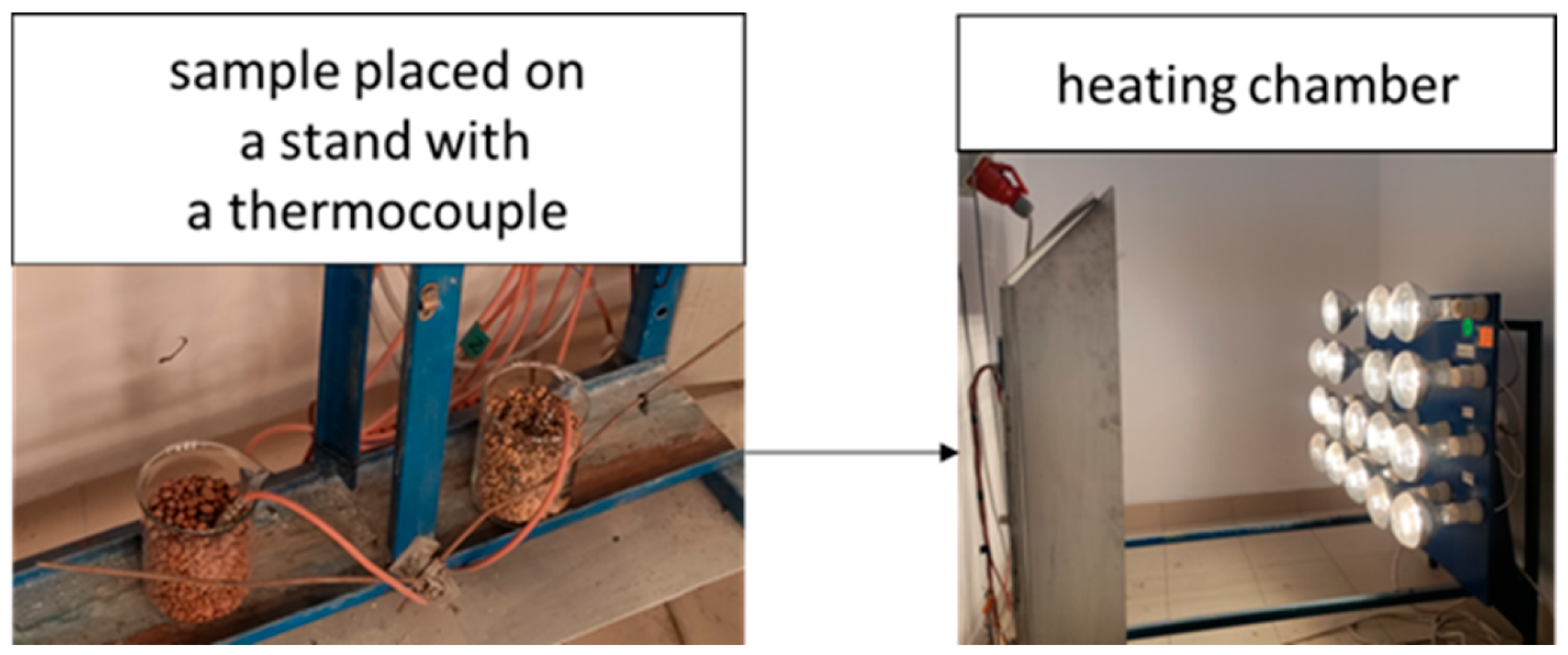
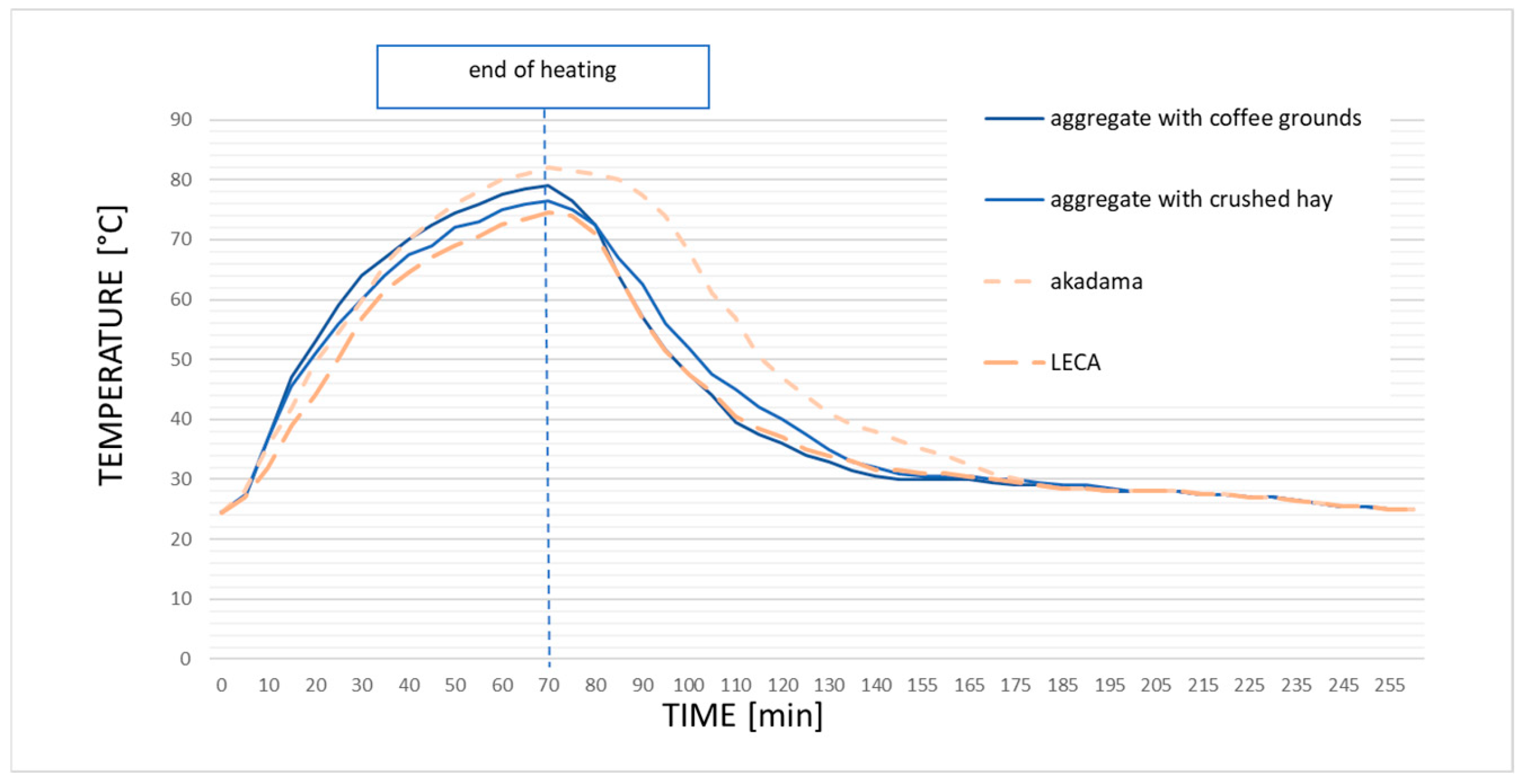
Analyzing the thermal properties of the aggregate was not the primary research objective; however, due to the spreading problem of urban heat spots, simulations of heating and free cooling with the samples were performed. The heating of the aggregates was tested in a climatic chamber using evenly distributed heat radiators with a power of 7 kW. A diagram of the research station is shown in Figure 2; it is equipped with sensors that set off an alarm when the temperature exceeds 95 °C. The distance between the radiators and the samples was 1.5 m, and the initial temperature of the chamber was 25 °C.

2.2.7. Methodology of Vegetation Test

The research plant used was oats, “Avena sativa”. The plant is well suited for phytotests because it has small and uniform seeds, balanced germination energy, and a short emergence period (24–48 h). In addition, it is characterized by a large biomass of roots and stems and is widely available and inexpensive. The conventional biotest consisted of sowing the plant seeds in the aggregate sample tested, followed by watering. The duration of biotest I was 7 days, after which the growth of the roots and leaves was determined by removing the plant from the aggregate, drying it at 105 °C, and weighing it on an analytical balance. The experiment was repeated. The second biotest lasted 14 days, and the green parts of the plants and roots were weighed separately.

3. Results and Discussion

3.1. Achievement of Sintered Aggregate

The structural changes in the raw material during sintering are caused by mass transfer phenomena. When heated to a temperature close to melting, a liquid phase is formed at the grain interface. The grains permanently fuse to form a polycrystal. In traditional technologies, the sintering process is performed to obtain a solid material with as little porosity as possible because high mechanical strength is desired. Producing lightweight aggregate from clays with the addition of biomass is also possible [49,50,51]. However, in this study, high-temperature microscopy was not used to precisely determine the initial sintering temperature. The temperature had to be high enough for the liquid phase to appear, but the process had to be stopped when the open porosity began to transform into closed porosity. Sintering was conducted in a way that could prevent the compaction of the material. The parameters of the sintering process can be determined using hot stage microscopy, which allows the transformation of a material to be observed under the influence of temperature. The greatest advantage of this method is that it allows for in situ observations of changes in the dimensions and shape of the sample during heating. The observations are continuous, and the camera records the course of the dimensional changes in the sample (shrinkage, cracking, and flow). The dependence of the dimensional change as a function of temperature makes it possible to determine the sintering temperature. This study often approximates the material properties of various industrial processes (Figure 3) [52,53].
It is assumed that the onset of shrinkage, i.e., a change in the linear dimensions of the sample, initiates the sintering process and the formation of the liquid phase. In Figure 3, the interval for the sample sintering process is from 1000 °C, where the sample begins to shrink, to 1150 °C, where the sample changes its linear dimensions by at least 5%. The process temperature was chosen below this interval because the idea was to obtain a porous sinter. Therefore, a temperature of 1050 °C was set. Carrying out this process ensures that the grains only adhere to each other through the formation of a minimum amount of liquid phase, while open porosity is simultaneously maintained in the structure. Notably, firing temperatures for commercial aggregates (expanded clay) are at least 1200 °C. At a temperature of approximately 1250 °C, a slight swelling of the Dubna Skala clay was observed (Figure 3). In subsequent experiments, the raw material was fired in an electric chamber kiln, and a temperature was chosen that would produce a durable sinter and high porosity. Sintering brings an additional benefit: the aggregate does not contain pathogenic organic elements such as fungi or pests.

3.2. Analysis of Selected Properties of Sintered Aggregates

3.2.1. Imaging and Structural Analysis

Due to its intended function, the structure and microstructure of the manufactured aggregate are extremely important. An adequate and well-developed network of pores and channels retains water and makes it available to plants. Roots will develop better in the rough surface of the granules. Porosity also ensures good aeration, which is often overlooked. Lucas et al. describe biopores, i.e., spaces above 100 μm, that allow for adequate root growth over time [54]. Depending on the way the pores are developed, three types of aggregates can be distinguished. Type one aggregates have predominantly large pore sizes (even above 1 mm) with an open structure; such aggregates have very good drainage and filtration properties and are good for growing roots. This is open macroporosity. Type two aggregates have a varied external pore structure, with a predominance of fine spherical pores (smaller than 0.1 mm) with a closed structure, and the interior of the grain has a predominance of larger pore sizes (even above 1 mm) with an open structure. This is open mesoporosity, which was the main research objective of this work. This type of aggregate will have both filtration and water-buffering capabilities. Type three aggregates have a predominance of fine, spherical pores (smaller than 0.1 mm) with a closed structure and are particularly valued in lightweight construction [55]. The sintered aggregates produced have structures characteristic of all three types, as they are determined by both the raw materials and the manufacturing technology. High-temperature sintering technology generally results in a tight coating on the outside of the grain and fine closed pores on the inside. Roces et al. and Rashad studied typical lightweight aggregates and found that the porosity of the expanded clay type is 70–90%, enclosed by a vitrified mineral mass [56,57]. This study presents a completely different perspective on porous aggregates.
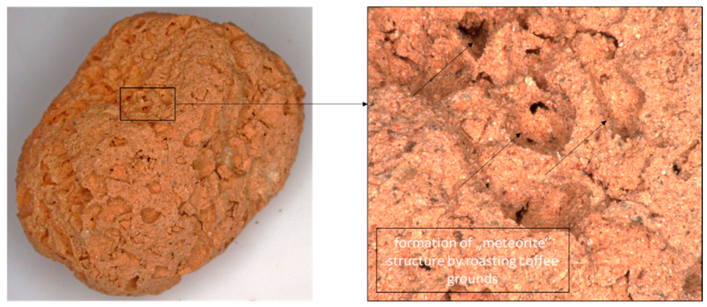
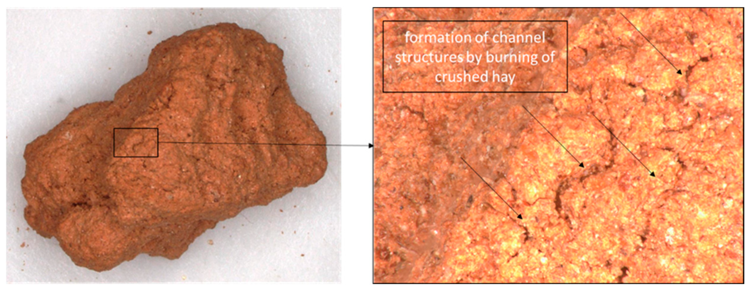
Crater-like structures were observed in aggregates that were roasted with the addition of spent coffee grinds, which were formed by burning organic matter (Figure 4). Similar observations were made by Andreola et al. and Farias et al. [49,50]. This surface roughness promotes rooting and water availability. In aggregates burned with the addition of crushed hay, tubular structures were formed; they were longer and with a smaller cross-section than the crater structure (Figure 5).
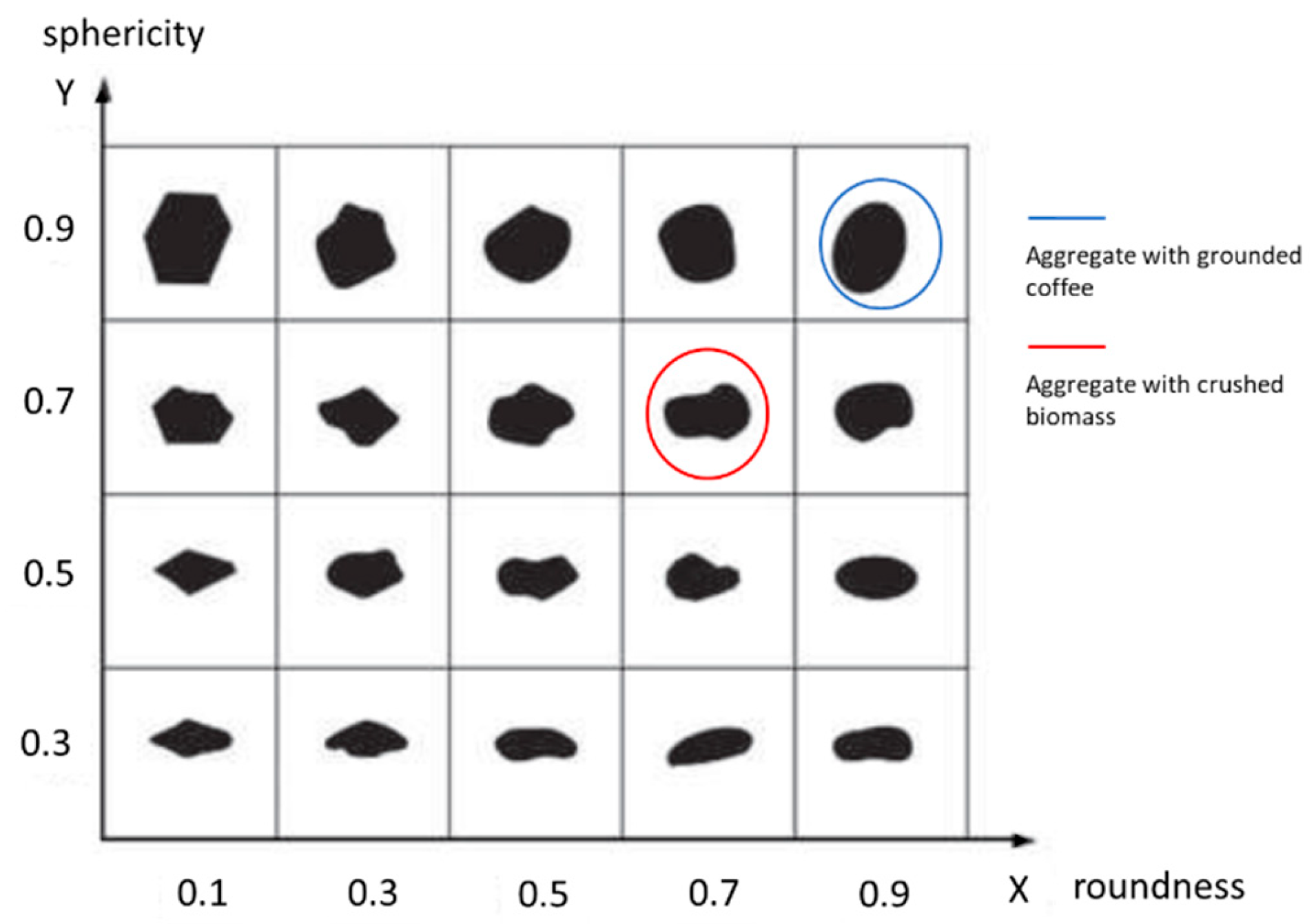
Regarding shape, aggregate grains can be classified as spherical based on the shape index of the Zingg diagram. However, aggregate grains differ slightly in their sphericity index and degree of dressing. The grains of the aggregates roasted with coffee show a sphericity index of 0.9, while the aggregates roasted with hay have a sphericity index of 0.7. Regarding the degree of roundness, the aggregate with coffee has a diagram index of 0.9, while the aggregate with hay has an index of 0.7 according to Krumbein and Sloss (Figure 6). The varying degree of aggregate grain turning is due to the different types of additives used to produce the aggregates, i.e., coffee and hay. The hay in the aggregate is a kind of network (matrix) filled with clay, giving the grains a lumpy shape (Figure 5).
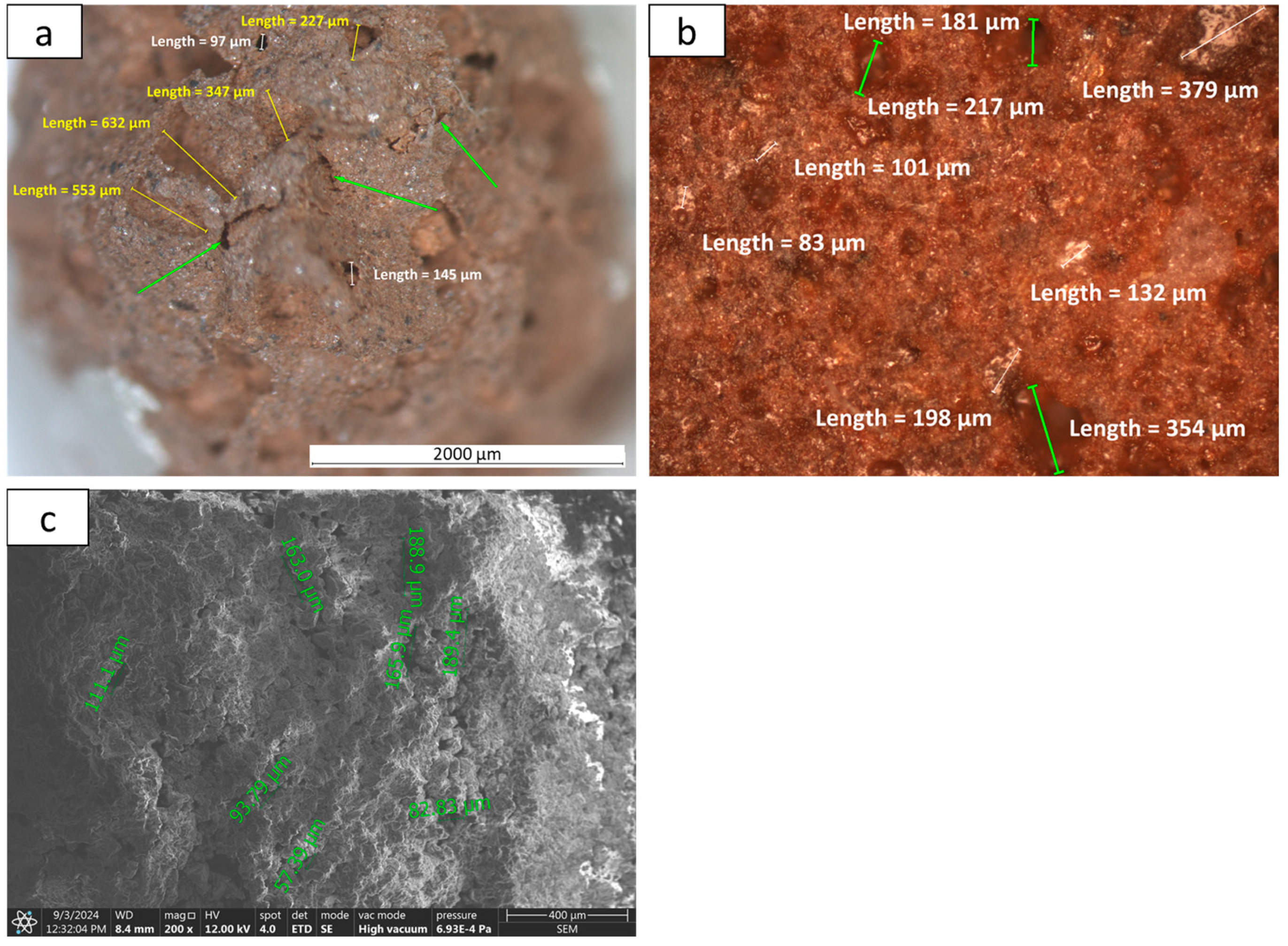
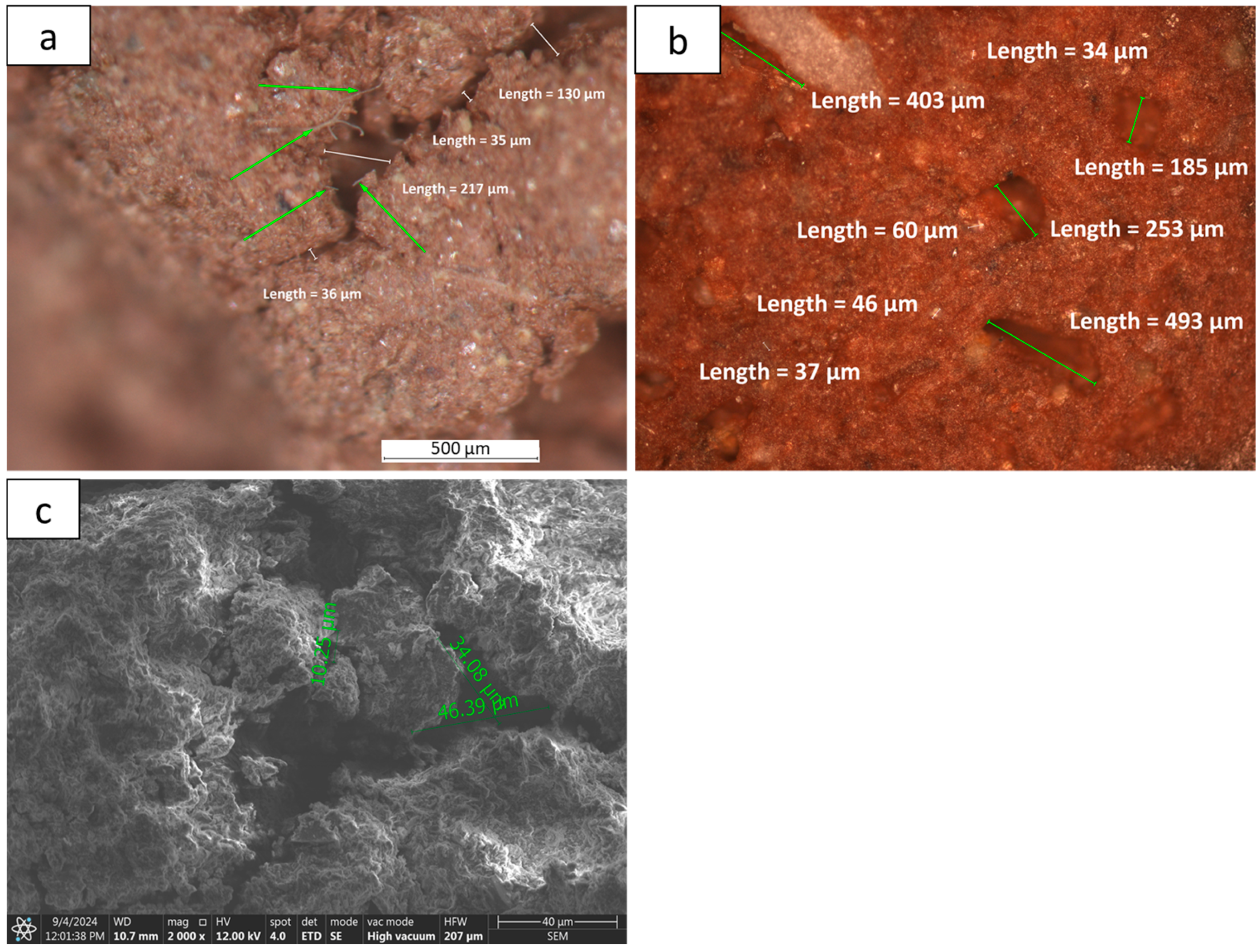
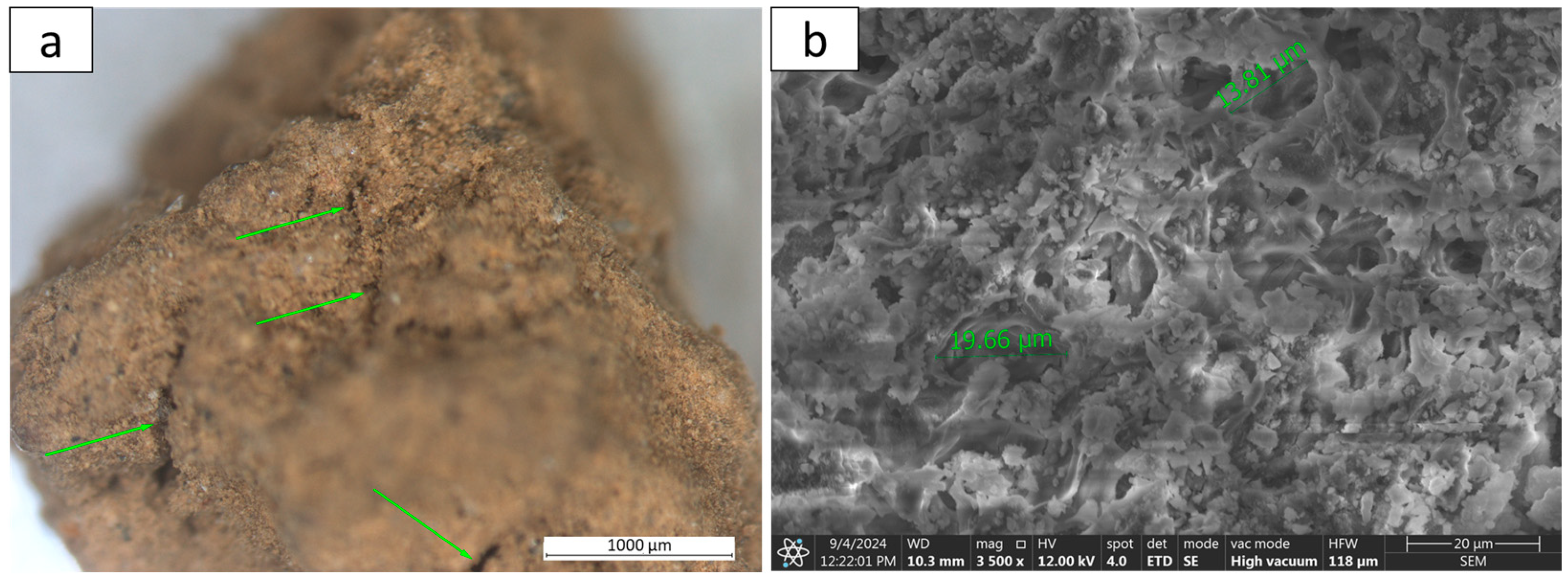
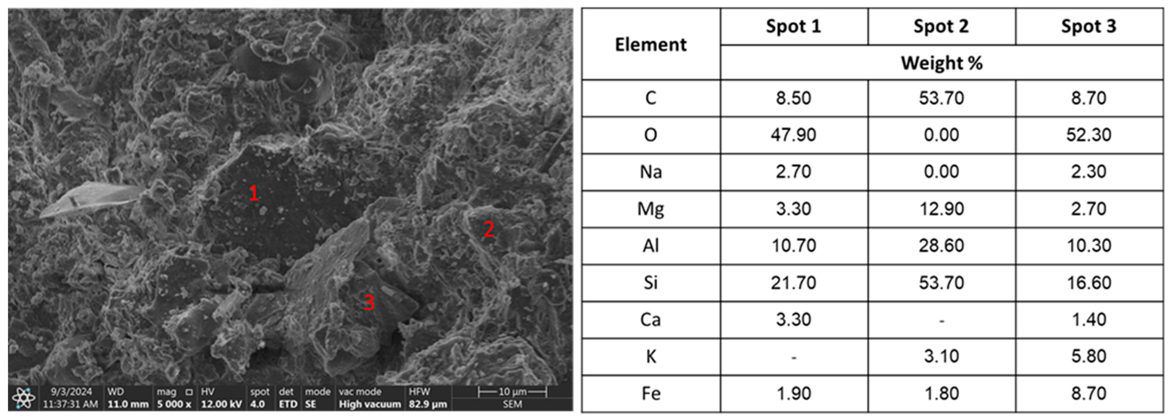
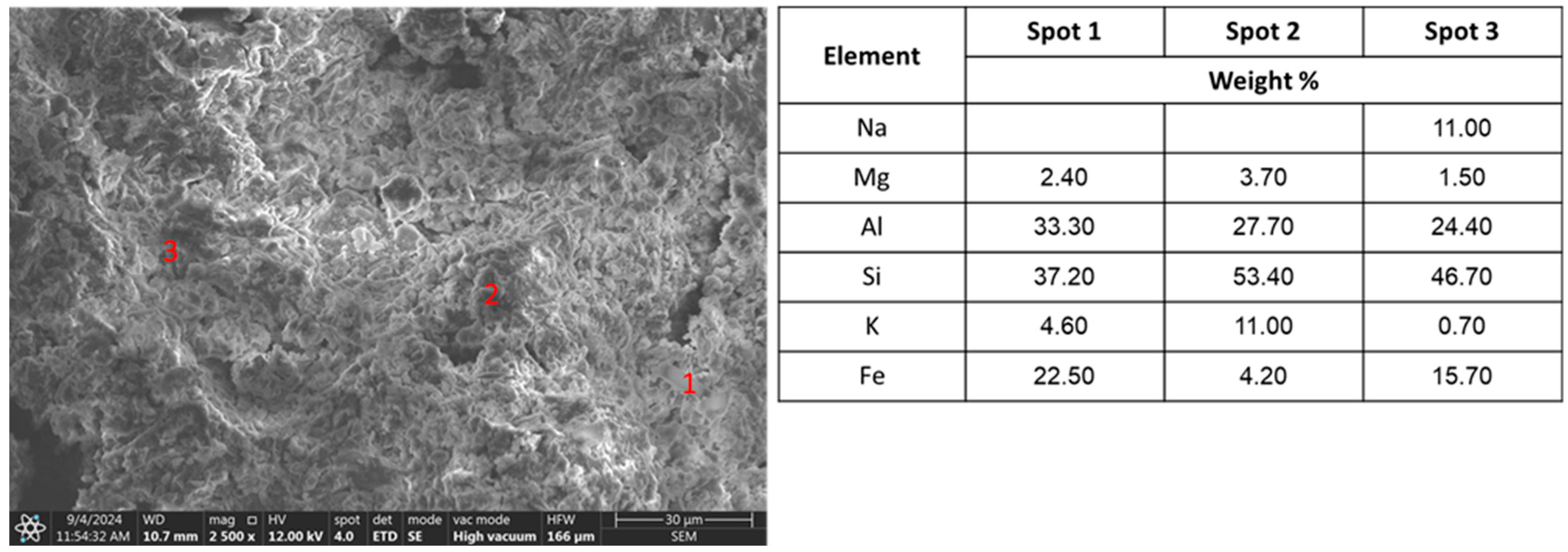
The pores of the aggregate with coffee are slightly larger, i.e., 0.030–0.060 mm (Figure 7), and those of the aggregate with crushed hay are up to 0.020 mm in size (Figure 8). In general, microscopic observations show that the aggregate with crushed hay (biomass) additions has the highest porosity, shaped mainly by the presence of fractures ranging in size from 0.100–0.500 mm (Figure 9). In addition, in the grains of the coffee aggregate, interesting voids were microscopically observed using a polarizing microscope, shaped like unhealed polygons. These likely formed during the manufacture of the aggregate (sintering process). Polygons have an average size between 0.100 and 0.300 mm. SEM-EDS analysis (Figure 10, Figure 11 and Figure 12) in all cases confirmed the presence of the aggregate additives used, i.e., hay and coffee grounds. Regarding the microstructure, the area subjected to SEM-EDS analysis showed a cryptocrystalline structure with well-preserved tabular praecrystalline crystals. A popular Japanese aggregate used as a vegetation layer was also imaged for comparison. The grains are the cryptocrystalline texture type, characteristic of formations of volcanic origin (glassy texture) with preserved phanerocrystalline relics (Figure 9). The predominant texture is weakly compact, and the grains show considerable brittleness, as observed during their preparation (no polarizing microscope scanning was possible). The grains of all aggregates have porosity in the form of significant caverns, fissures, and irregularly shaped voids, forming a connected system (Figure 10, Figure 11 and Figure 12). Microscopic examinations of LECA aggregate were not carried out because it is a well-known and widely available material; its microstructure has been extensively studied by authors such as Domagała, Roces et al., and Rashad [55,56,57]. During the manufacturing process, the clay expands so that the grains have a heterogeneous structure, formed by a rigid outer shell and a highly porous core that provides them with their characteristic lightness. Some of these voids are accessible, so they can be saturated, while others are inaccessible. Given the above, the LECA aggregate has double porosity: a grain interior on one side and an inter-grain porosity on the other. However, this study focused specifically on the open porosity obtained in the aggregate because of porosity-enhancing additives and appropriate sintering.
Elemental analyses were performed in the micro-areas because bioavailable elements such as Mg and K are important for the use of aggregates in the vegetation layer. However, the goal is not luxuriant growth, as a green roof should, by definition, be planted with dwarf and slow-growing plants that can withstand extreme conditions.

3.2.2. Apparent and Bulk Density

Aggregates used as substrates for green roofs should have as low a density as possible; obviously, well-developed porosity has an important influence on the density of the material. In our study, the parameters of the resulting aggregate are very similar, and the variability is small, as the measurements were repeated five times. The apparent density of the aggregates (Table 4) varies little between individual samples, and the average values range from 1.47 to 1.53 g/cm3. The standard EN 13055:2016 [58] covers LWAs of mineral origin with a particle density not exceeding 2.00 kg/m3 or loose bulk density not exceeding 1.20 kg/m3 derived from natural, manufactured, or recycled sources [58]. The apparent densities of the aggregates obtained are not higher than those specified in the standard, but they differ significantly from typical lightweight aggregates, e.g., expanded clay at ~0.5 g/cm3. The bulk density of all aggregates tested is also similar and meets the aforementioned standard. Through pore-forming additives and a suitable sintering process, an aggregate lighter than similar aggregates was obtained. The literature data indicate bulk densities of 1.1–1.4 g/cm3 [49,50].

3.2.3. Resistance to Abrasion, Crushing, and Disintegration Under the Influence of Water

If an aggregate is to carry heavy loads, it must have a high static strength (crushing, compression). This is expected for construction aggregates. Lightweight aggregates for green roofs do not carry such loads and, therefore, do not require high compressive strength. However, their dynamic strength (abrasion) is important; it is a matter of transport and incorporation into the green roof, eliminating process dust. As a result of environmental factors—mainly the action of water—aggregate grains can also disintegrate during the operation of a green roof. A dust fraction then forms, which settles at the bottom of the drainage layer. This can interfere with the drainage of excess water, reduce the aeration of the substrate, and affect plant growth. Therefore, a simple test was carried out to disintegrate the aggregate in water. Table 5 and Table 6 present the results of the granule abrasion and crushing strength tests. Table 7 presents the aggregate’s resistance to soaking. Each crushing test included 30 measurements of granules at the selected 4–6.3 mm fraction. For abrasion strength tests, 10 grains were taken, and the measurement time was 10 min at a machine speed of 20 rpm. The abrasion resistance tests were performed five times.
The static strength of the aggregates varied. The strongest aggregate was obtained with coffee and LECA (average greater than 150 N). The weakest aggregate, i.e., akadama, was obtained with an average of about 20 N. The method of aggregate production must be considered. LECA is a sintered aggregate whose surface is melted (glaze), while akadama is heated without forming bonds between minerals. Akadama is baked at low temperatures without strengthening phase transformations; therefore, its strength is low. In each of the tests, high values in the standard deviation of the measurements were observed (Table 5). This is particularly the case with the aggregate with hay; the burnt biomass particles create long channels that reduce mechanical strength. However, as mentioned earlier, aggregates designed for green roofs and living walls do not transfer loads, so it is not necessary to have high and stable strength. A much more important parameter is resistance to abrasion, which is high in the aggregates obtained, about 1% on average. The maximum unfavorable mass loss obtained in the tests was 1.62% (aggregate with coffee), which is a satisfactory result.
The aggregates on a roof will be subjected to variable watering conditions. The idea is for water to soak into them but not cause disintegration; in other words, the aggregate should be durable and not disintegrate in water. Therefore, a quick disintegration test was performed in 10 min (Table 7). Samples of sintered aggregate passed this test positively, while the akadama disintegrated under pressure.

3.2.4. Total Retention and Water Release Process

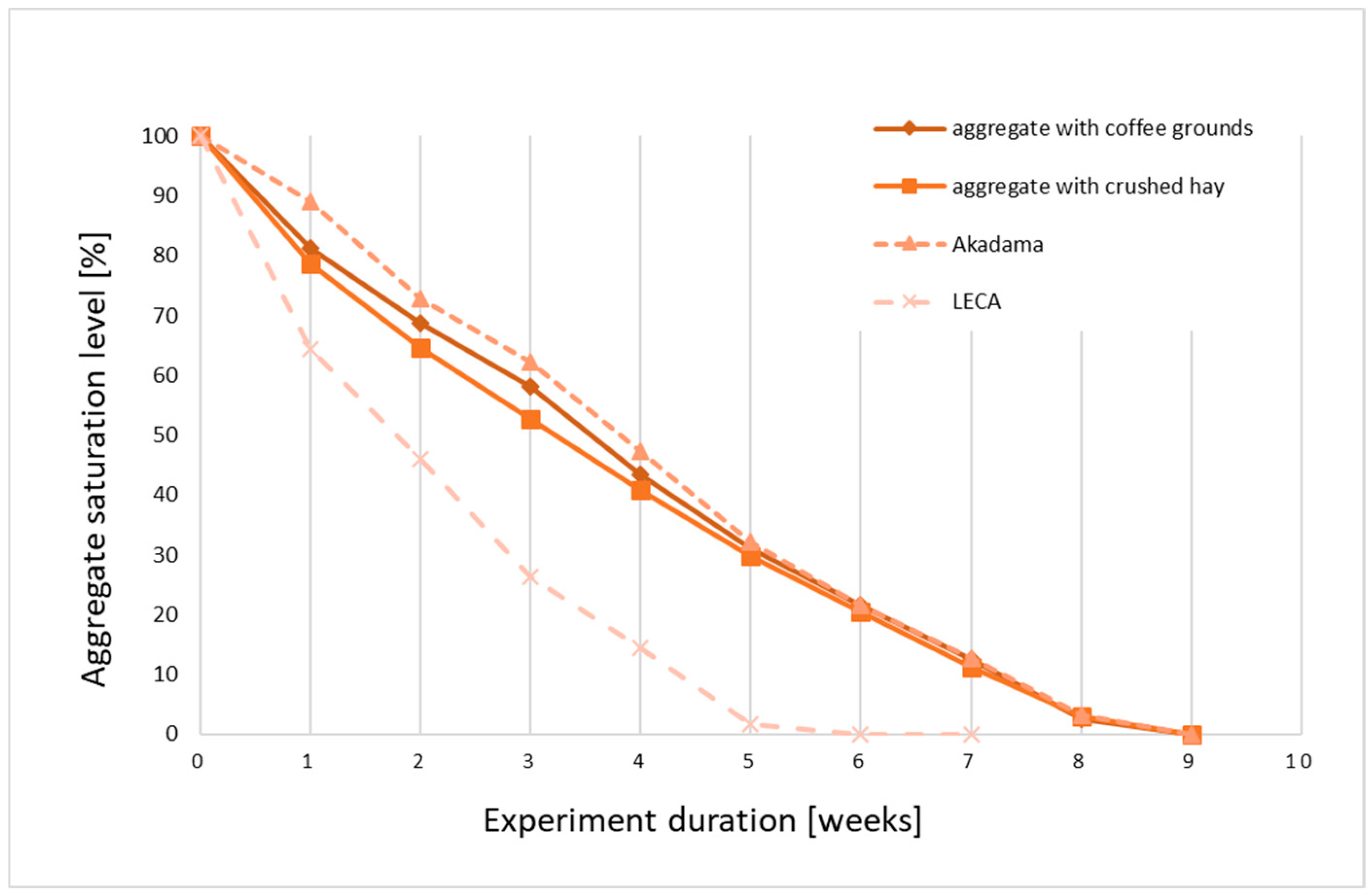
This study aimed to create a material that supports moisture management in the vegetation layer of green roofs. Natural weather conditions usually do not provide even irrigation, and recently, rainfall has been intense, short, or non-existent for long periods. Therefore, two main factors should be considered: first, the effective retention of some water during storm rain, i.e., short-term retention, and second, the longer retention of moisture available to plants. In an ideal situation, it would be possible to eliminate additional watering during periods of prolonged drought. Of course, moisture retention cannot be the ultimate result, especially in cases of high sunlight, which occurs in most roof gardens. However, buffering water for a period of several weeks in deeper layers of the substrate would significantly reduce the need for irrigation. Kaczmarczyk et al., Al-Bulsaltan et al., and Yang et al. indicate that water permeability depends on the porosity and shape of the materials used in the substrate layer of the green roof [47,59,60]. Furthermore, Wong et al. and Ouldboukhitine et al. showed that the use of highly porous materials, such as mineral wool, in the substrate layer increases the porosity and permeability of green roof systems [61,62,63]. An aggregate’s water retention and drying dynamics are very important during the use and maintenance of a green roof. The rate of absorption and water release depends on the pore structure. Changes in moisture content during the aggregates tested are shown in Figure 13. In the initial drying phase, the moisture values of the individual samples are already different. The average change in moisture for clay samples after a week is about 20%. However, a change in the drying rate is visible from the beginning, and the difference between individual samples increases. Expanded clay aggregate dries the fastest, reaching a constant mass after about 5 weeks. Akadama remains in a saturated state the longest because its production takes place at lower process temperatures, which do not cause phase changes in clay minerals. Clay minerals, especially if they are mixed packages, can retain large amounts of water, and akadama contains imogolite, which is a hydrated aluminum silicate [59,60]. After 9 weeks, all samples were dry. Hill et al. made similar observations. Mineral products, such as crushed bricks and lightweight aggregates, did not contain measurable amounts of water after several weeks [44]. A good solution is to mix mineral fractions with organic matter, and a good practice in green roof design is to ensure that organic matter does not constitute more than 10% of the vegetation layer by weight.
Since the aggregates were fired with the addition of biomass, crushed hay, and coffee grounds, we expected that the components would be washed out of the resulting ash. For this purpose, the samples were immersed in distilled water with a pH of 6.38 and a base conductivity of ~50 µS for 24 h. After this time, the electrolytic conductivity of the water effluents was tested (Table 8). The pH remained close to neutral and was similar to that of other materials used for green roofs obtained by Andreola et al., Kim et al., and Schwager et al. [49,64,65]. The literature indicates that at the design stage, it is necessary to analyze the materials used in the substrate preparation process. The results show that the conductivity of the solutions formed after rinsing the fired aggregates differs significantly from that of commercial aggregate. A significant increase in the conductivity of the solution (>1 mS) was observed, indicating leaching of useful components. The EDS elemental analysis (Figure 10 and Figure 11) may suggest that the migrating cations are mainly Na, K, Ca, and Mg. No hazardous or harmful elements were found. Further research is currently being conducted in this area, especially regarding the retention of pollutants by green roof layers. Due to climate change and dense development, heavy rains are becoming more common in cities. The water that runs off is lost forever, and therefore, the aggregate in the green roof is meant to quickly absorb water; this is called short-term retention. Due to its well-developed porosity, about 30–40% of precipitation should be retained by the aggregate. These results are consistent with research by other authors. Peczkowski et al. indicate that peak rainfall flow rates can be reduced by approximately 30% using green roofs [66]. In total, 1 m2 of loosely laid 10 cm thick aggregate layer will retain approximately 25 L of water. The results are presented in Table 8.
Total water retention is the amount of water retained in the aggregate in percentage terms. A green retention roof can store large amounts of rainwater, which significantly improves water balance and counteracts the effects of drought. Despite its very low bulk density, typical lightweight LECA aggregate has relatively low water absorption because its structure is dominated by closed porosity. This porosity is practically irrelevant in the case of water absorption during heavy rainfall, but the aggregate can still be used as a drainage layer. The sintered aggregates produced with hay and coffee have the highest retention capacity, averaging more than 35% compared with other tested aggregates. If the aggregate absorbs water very well, the retention capacity may be equal to the total water absorption.

3.2.5. Thermal Properties

For comparison, in addition to the aggregates produced, we also tested a typical lightweight aggregate of the expanded clay type and Japanese akadama, which are used in horticulture. The same sample volume was tested, i.e., 200 cm3, and the results of these tests are presented in the form of heating-free cooling curves in Figure 14. In general, the aggregates behave similarly, and no significant differences between the aggregates were observed. This is because they are chemically similar and do not contain significant amounts of heat-accumulating oxides [67]. We observed that the LECA-type aggregate heats up slightly less due to its lower density. Studies using a thermal imaging camera conducted by Farias et al. indicate that the temperature drop is approximately 18% for high-porosity (low-density) aggregates [50]. The alarm temperatures were not exceeded during the tests.

3.2.6. Vegetation Test

The material filling the structure of a green roof or living wall should play two basic roles:
(1)
Supporting the roots and maintaining the plant in space;
(2)
Maintaining humidity and the required nutrient contents.
Aggregate samples were used in pot vegetation studies (Figure 15).
The green parts were cut separately on the surface and dried, and the roots were separated from the substrate and also dried. The plants were watered twice, the first time directly after sowing and the second time a week after sowing. Note that the research was conducted only on the aggregate produced; no nutrients or fertilizers were used to support plant growth. Aggregates containing silica gels (akadama) can feed plants themselves [68,69,70].
Biomass aggregates have ash in their structure, which can release bioavailable elements. The tests were conducted for illustrative purposes to determine whether the plant would stably root and root on the substrate produced. Table 9 presents the masses of the dried plant parts. The first biotest did not show significant differences; the increase in biomass was 0.4–0.5 g, regardless of the aggregate. The probable cause was the experiment being too short; the second test was extended to two weeks. In the second biotest, the increase in biomass was mainly concentrated in the roots, and in the LECA aggregate, it is clearly lower (Table 9). Therefore, the porosity of the aggregate has a significant effect on the development of plant roots, which we attempted to demonstrate in the tests (Table 9), as shown in Figure 15. The literature data indicate that porosity should be above 20% for plant growth and rooting [64]. Lucas et al. demonstrate that connectivity between pores, i.e., open porosity, is crucial, and biopore size should be greater than 100 μm [54]. However, the interactions between plant roots and the structure of the vegetation layer are bidirectional. During exploration, roots break through the substrate and change the physical, chemical, and biological properties of their surroundings. Therefore, long-term tests are necessary.

4. Conclusions

A prospective lightweight aggregate that can be used as a substrate for green roofs and walls was produced. It is characterized by several important features:
  • A properly conducted burning process obtained an open porous microstructure with a crater system (aggregate with coffee) or a crevice system (aggregate with crushed hay);
  • The aggregate is chemically neutral, does not react with the mineral components of the water medium, and releases useful components (filtrate conductivity greater than 1000 µS);
  • The structure of the material ensures permeability and retention for air and water, which was visualized microscopically and analytically tested (water absorption above 40% and retention above 35%);
  • The aggregate is not subject to water, cannot change shape, and does not fall apart or crack;
  • The mass of the substrate will not affect the statics of the wall or roof structure; the obtained material meets the standards for lightweight aggregate (apparent density of approximately 1.5 g/cm3 and bulk density of approximately 0.7 g/cm3)
It is also worth noting the positive aspects of the life cycle of such a product. First, raw materials that were considered waste are used to produce aggregates. Currently, these waste products are stored in landfills and sedimentation ponds. This protects natural resources. Commercial aggregates are produced from naturally occurring clays, which are often in short supply. In addition, the firing temperature in our study was approximately 200 °C lower than the process temperature for firing expanded clay aggregate (LECA), which means that there are economic and emission benefits to using this process (less fuel burned; less CO2). Further work will involve creating an experimental garden, where extensive vegetation tests will be conducted using the produced aggregates. After validating the results under natural environmental conditions, action will be taken to increase the scale of aggregate production.

Funding

Research project partly supported by the program “Excellence initiative—research university” AGH of Kraków.

Institutional Review Board Statement

Not applicable.

Informed Consent Statement

Not applicable.

Data Availability Statement

The data are available upon request.

Conflicts of Interest

The author declares no conflicts of interest.

References

  1. Jim, C.Y. Archaeological and historical exploration of the origins of green roofs. Urban For. Urban Green. 2017, 27, 32–42. [Google Scholar] [CrossRef]
  2. Gutierrez, A.; Bohn, V.J.; Marinangeli, P. Nature-based solutions for sustainable cities: A review of the state of the art of green roof research. J. Sustain. Constr. Mater. Technol. 2025, 10, 93–107. [Google Scholar] [CrossRef]
  3. Fernandez-Cañero, R.; Emilsson, T.; Fernandez-Barba, C.; Machuca, M.Á.H. Green roof systems: A study of public attitudes and preferences in southern Spain. J. Environ. Manag. 2013, 128, 106–115. [Google Scholar] [CrossRef]
  4. Magliocco, A.; Perini, K. The perception of green integrated into architecture: Installation of a green facade in Genoa, Italy. AIMS Environ. Sci. 2015, 2, 899–909. [Google Scholar] [CrossRef]
  5. Molari, M.; Dominici, L.; Manso, M.; Matos Silva, C.; Comino, E. A socio-ecological approach to investigate the perception of green walls in cities: A comparative analysis of case studies in Turin and Lisbon. Nat.-Based Solut. 2024, 6, 100175. [Google Scholar] [CrossRef]
  6. Nagase, A.; Koyama, S. Attractiveness and preference of extensive green roofs depend on vegetation types and past experience with plants in Japan. Urban Green. 2020, 51, 126658. [Google Scholar] [CrossRef]
  7. Nagase, A.; Tashiro-Ishii, Y. Habitat template approach for green roofs using a native rocky sea coast plant community in Japan. J. Environ. Manag. 2018, 206, 255–265. [Google Scholar] [CrossRef]
  8. Nagase, A.; Yamada, Y.; Aoki, T.; Nomura, M. Developing biodiverse green roofs for Japan: Arthropod and colonizer plant diversity on Harappa and Biotope roofs. Urban Nat. 2018, 1, 16–38. [Google Scholar]
  9. Wong, N.H.; Cheong, D.W.; Yan, H.; Soh, J.; Ong, C.L.; Sia, A. The effects of rooftop garden on energy consumption of a commercial building in Singapore. Energy Build. 2003, 35, 353–364. [Google Scholar] [CrossRef]
  10. Wong, N.H.; Tan, A.Y.K.; Tan, P.Y.; Sia, A.; Wong, N.C. Perception studies of vertical greenery systems in Singapore. J. Urban Plan. Dev. 2010, 136, 330–338. [Google Scholar] [CrossRef]
  11. Bureau of Environment. 2021 Rooftop Gardening. Available online: https://www.kankyo.metro.tokyo.lg.jp/nature/green/roof_plant/actual.html (accessed on 31 May 2024).
  12. Jim, C.Y.; Hui, L.C.; Rupprecht, C.D.D. Public Perceptions of Green Roofs and Green Walls in Tokyo, Japan: A Call to Heighten Awareness. Environ. Manag. 2022, 70, 35–53. [Google Scholar] [CrossRef]
  13. Zhang, J.; Yu, Z.; Zhao, B.; Sun, R.; Vejre, H. Links between green space and public health: A bibliometric review of global research trends and future prospects from 1901 to 2019. Environ. Res. Lett. 2020, 15, 063001. [Google Scholar] [CrossRef]
  14. Fei, Y.; Fu, D.; Xu, C.; Singh, R.P. Component design optimization of green roof substrate layer based on the assessment of multifunctional performance. Environ. Res. 2023, 238, 117190. [Google Scholar] [CrossRef] [PubMed]
  15. Luchkina, V. Application of Green Roofing Technologies as Site Landscaping. IOP Conf. Ser. Mater. Sci. Eng. 2020, 869, 022008. [Google Scholar] [CrossRef]
  16. Di Miceli, G.; Iacuzzi, N.; Licata, M.; La Bella, S.; Tuttolomondo, T.; Aprile, S. Growth and development of succulent mixtures for extensive green roofs in a Mediterranean climate. PLoS ONE 2022, 17, e0269446. [Google Scholar] [CrossRef] [PubMed]
  17. Getter, K.L.; Rowe, D.B. The Role of Extensive Green Roofs in Sustainable Development. Hortscience 2006, 41, 1276–1285. [Google Scholar] [CrossRef]
  18. Pęczkowski, G.; Orzepowski, W.; Pokładek, R.; Kowalczyk, T.; Żmuda, R.; Wójcik, R. Retention properties of the type of extensive green roofs as an example of model tests. Acta Sci. Polonorum. Form. Circumiectus 2016, 15, 113. [Google Scholar] [CrossRef]
  19. Rosasco, P.; Perini, K. Selection of (Green) Roof Systems: A Sustainability-Based Multi-Criteria Analysis. Buildings 2019, 9, 134. [Google Scholar] [CrossRef]
  20. Kazemi, M.; Courard, L.; Hubert, J. Coarse recycled materials for the drainage and substrate layers of green roof system in dry condition: Parametric study and thermal heat transfer. J. Build. Eng. 2022, 45, 103487. [Google Scholar] [CrossRef]
  21. Zhang, Z.; Szota, C.; Fletcher, T.D.; Williams, N.S.; Farrell, C. Green roof storage capacity can be more important than evapotranspiration for retention performance. J. Environ. Manag. 2019, 232, 404–412. [Google Scholar] [CrossRef] [PubMed]
  22. Santamouris, M. Cooling the cities—A review of reflective and green roof mitigation technologies to fight heat island and improve comfort in urban environments. Sol. Energy 2014, 103, 682–703. [Google Scholar] [CrossRef]
  23. Takakura, T.; Kitade, S.; Goto, E. Cooling effect of greenery cover over a building. Energy Build. 2000, 31, 1–6. [Google Scholar] [CrossRef]
  24. Köhler, M.; Schmidt, M.; Grimme, F.W.; Laar, M.; Gusmão, F. Urban water retention by greened roofs in temperate and tropical climate. Technol. Resour. Manag. Dev. 2001, 2, 151–162. [Google Scholar]
  25. Lata, J.-C.; Dusza, Y.; Abbadie, L.; Barot, S.; Carmignac, D.; Gendreau, E.; Kraepiel, Y.; Mériguet, J.; Motard, E.; Raynaud, X. Role of substrate properties in the provision of multifunctional green roof ecosystem services. Appl. Soil Ecol. 2018, 123, 464–468. [Google Scholar] [CrossRef]
  26. Berardi, U.; GhaffarianHoseini, A.H.; GhaffarianHoseini, A. State-of-the-art analysis of the environmental benefits of green roofs. Appl. Energy 2014, 115, 411–428. [Google Scholar] [CrossRef]
  27. Sutton, K.R. Green Roof Ecosystems; Ecological Studies; Springer International Publishing: Cham, Switzerland, 2015; Volume 223. [Google Scholar]
  28. Molineux, C.J.; Gange, A.C.; Connop, S.P.; Newport, D.J. Using recycled aggregates in green roof substrates for plant diversity. Ecol. Eng. 2015, 82, 596–604. [Google Scholar] [CrossRef]
  29. Rahman, M.S.; MacPherson, S.; Lefsrud, M. Prospects of porous concrete as a plant-growing medium and structural component for green roofs: A review. Renew. Agric. Food Syst. 2020, 37, 536–549. [Google Scholar] [CrossRef]
  30. Eksi, M.; Sevgi, O.; Akburak, S.; Yurtseven, H.; Esin, İ. Assessment of recycled or locally available materials as green roof substrates. Ecol. Eng. 2020, 156, 105966. [Google Scholar] [CrossRef]
  31. Mickovski, S.B.; Buss, K.; McKenzie, B.M.; Sökmener, B. Laboratory study on the potential use of recycled inert construction waste material in the substrate mix for extensive green roofs. Ecol. Eng. 2013, 61, 706–714. [Google Scholar] [CrossRef]
  32. Stempkowska, A.; Gawenda, T. Improved Artificial Aggregates for Use in Green Roof Design. Sustainability 2024, 16, 5512. [Google Scholar] [CrossRef]
  33. Stempkowska, A.; Gawenda, T. Artificial lightweight aggregate made from alternative and waste raw materials, hardened using the hybrid method. Sci. Rep. 2024, 14, 16880. [Google Scholar] [CrossRef]
  34. Stempkowska, A.; Gawenda, T.; Staszewska, M. Lightweight alternative aggregate: Characteristics, parameters, application possibilities. In Kruszywa Mineralne; Oficyna Wydawnicza Politechniki Wrocławskiej: Wrocław, Poland, 2024; Volume 7, pp. 187–188. [Google Scholar]
  35. Bates, A.J.; Sadler, J.; Greswell, R.B.; Mackay, R. Effects of recycled aggregate growth substrate on green roof vegetation development: A six year experiment. Landsc. Urban Plan. 2015, 135, 22–31. [Google Scholar] [CrossRef]
  36. Shahmohammad, M.; Hosseinzadeh, M.; Dvorak, B. Sustainable green roofs: A comprehensive review of influential factors. Environ. Sci. Pollut. Res. 2022, 29, 78228–78254. [Google Scholar] [CrossRef] [PubMed]
  37. Vannucchi, F.; Buoncristiano, A.; Scatena, M.; Caudai, C.; Bretzel, F. Low productivity substrateleads to functional diversification of green roof plant assemblage. Ecol. Eng. 2022, 176, 106547. [Google Scholar] [CrossRef]
  38. Coulibaly, S.F.M.; Aubry, C.; Provent, F.; Rousset-Rouvière, S.; Joimel, S. The role of green roofs as urban habitats for biodiversity modulated by their design: A review. Environ. Res. Lett. 2023, 18, 073003. [Google Scholar] [CrossRef]
  39. Farrell, C.; Cao, C.T.N.; Ang, X.Q.; Rayner, J.P. Use of water-retention additives to improve performance of green roof substrates. Acta Hortic. 2016, 1108, 271–278. [Google Scholar] [CrossRef]
  40. Graceson, A.; Hare, M.; Monaghan, J.; Hall, N. The water retention capabilities of growing media for green roofs. Ecol. Eng. 2013, 61, 328–334. [Google Scholar] [CrossRef]
  41. Mentens, J.; Raes, D.; Hermy, M. Greenroofs as a part of urban water management. Prog. Water Resour. 2003, 8, 35–43. [Google Scholar]
  42. Latshaw, K.; Fitzgerald, J.; Sutton, R. Analysis of Green Roof Growing Media Porosity. RURALS Rev. Undergrad. Res. Agric. Life Sci. 2009, 4, 2. [Google Scholar]
  43. Yudina, A.V.; Klyueva, V.V.; Romanenko, K.A.; Fomin, D.S. Micro- within macro: How micro-aggregation shapes the soil pore space and water-stability. Geoderma 2022, 415, 115771. [Google Scholar] [CrossRef]
  44. Hill, J.; Sleep, B.; Drake, J.; Fryer, M. The effect of intraparticle porosity and interparticle voids on the hydraulic properties of soilless media. Vadose Zone J. 2019, 18, 180176. [Google Scholar] [CrossRef]
  45. Kazemi, M.; Courard, L.; Attia, S. Water permeability, water retention capacity, and thermal resistance of green roof layers made with recycled and artificial aggregates. Build. Environ. 2023, 227, 109776. [Google Scholar] [CrossRef]
  46. Pettersson, K.; Maggiolo, D.; Sasic, S.; Johansson, P.; Sasic-Kalagasidis, A. On the impact of porous media microstructure on rainfall infiltration of thin homogeneous green roof growth substrates. J. Hydrol. 2020, 582, 124286. [Google Scholar] [CrossRef]
  47. Karczmarczyk, A.; Baryła, A.; Kożuchowski, P. Design and Development of Low P-Emission Substrate for the Protection of Urban Water Bodies Collecting Green Roof Runoff. Sustainability 2017, 9, 1795. [Google Scholar] [CrossRef]
  48. Aggregates Europe. Available online: https://www.aggregates-europe.eu/facts-figures/figures/ (accessed on 7 July 2025).
  49. Andreola, F.; Borghi, A.; Pedrazzi, S.; Allesina, G.; Tartarini, P.; Lancellotti, I.; Barbieri, L. Spent Coffee Grounds in the Production of Lightweight Clay Ceramic Aggregates in View of Urban and Agricultural Sustainable Development. Materials 2019, 12, 3581. [Google Scholar] [CrossRef] [PubMed]
  50. Farías, R.D.; Martínez García, C.; Cotes Palomino, T.; Martínez Arellano, M. Effects of Wastes from the Brewing Industry in Lightweight Aggregates Manufactured with Clay for Green Roofs. Materials 2017, 10, 527. [Google Scholar] [CrossRef]
  51. García, C.M.; Palomino, T.C.; Godino, F.J.I.; Iglesias, F.A.C. Porosity of expanded clay manufactured with addition of sludge from the brewing industry. Int. J. Energy Environ. Eng. 2014, 5, 341–347. [Google Scholar] [CrossRef]
  52. Boccaccini, A.R.; Hamann, B. Review In Situ high-temperature optical microscopy. J. Mater. Sci. 1999, 34, 5419–5436. [Google Scholar] [CrossRef]
  53. Kang, S.J.L. Sintering, Densification, Grain Growth & Microstructure; Elsevier: Oxford, UK, 2005. [Google Scholar]
  54. Lucas, M.; Schlüter, S.; Vogel, H.J.; Vetterlein, D. Roots compact the surrounding soil depending on the structures they encounter. Sci. Rep. 2019, 9, 16236. [Google Scholar] [CrossRef]
  55. Domagała, L. Structural Lightweight Aggregate Concrete/Konstrukcyjne Lekkie Betony Kruszywowe; CUT Publishing House: Cracow, Poland, 2014. (In Polish) [Google Scholar]
  56. Roces, E.; Muñiz-Menéndez, M.; González-Galindo, J.; Estaire, J. Lightweight expanded clay aggregate properties based on laboratory testing. Constr. Build. Mater. 2021, 313, 125486. [Google Scholar] [CrossRef]
  57. Rashad Alaa, M. Lightweight expanded clay aggregate as a building material—An overview. Constr. Build. Mater. 2018, 170, 757–775. [Google Scholar] [CrossRef]
  58. EN 13055:2016; Lightweight Aggregates. European Committee for Standardization (CEN): Brussels, Belgium, 2016.
  59. Al-Busaltan, S.; Amoori Kadhim, M.; Nile, B.K.; Alshama, G.A. Evaluating Porous Pavement for the Mitigation of Stormwater Impacts. IOP Conf. Ser. Mater. Sci. Eng. 2021, 1067, 012052. [Google Scholar] [CrossRef]
  60. Yang, M.; Dong, W.; Cheng, R.; Wang, H.; Zhao, Z.; Wang, F.; Wang, Y. Effect of highly efficient substrate modifier, super-absorbent polymer, on the performance of the green roof. Sci. Total Environ. 2022, 806, 150638. [Google Scholar] [CrossRef] [PubMed]
  61. Wong, G.K.L.; Jim, C.Y. Quantitative hydrologic performance of extensive green roof under humid-tropical rainfall regime. Ecol. Eng. 2014, 70, 366–378. [Google Scholar] [CrossRef]
  62. Ouldboukhitine, S.-E.; Belarbi, R.; Djedjig, R. Characterization of green roof components: Measurements of thermal and hydrological properties. Build. Environ. 2012, 56, 78–85. [Google Scholar] [CrossRef]
  63. Ouldboukhitine, S.-E.; Belarbi, R. Experimental characterization of green roof components. Energy Proc. 2015, 78, 1183–1188. [Google Scholar] [CrossRef]
  64. Kim, H.-H.; Kim, C.-S.; Jeon, J.-H.; Lee, S.-K.; Park, C.-G. Performance Evaluation and Field Application of Red Clay Green Roof Vegetation Blocks for Ecological Restoration Projects. Sustainability 2017, 9, 357. [Google Scholar] [CrossRef]
  65. Schwager, J.; Schaal, L.; Simonnot, M.; Claverie, R.; Ruban, V.; Morel, J.L. Emission of trace elements and retention of Cu and Zn by mineral and organic materials used in green roofs. J. Soils Sediments Prot. Risk Assess. Remediat. 2015, 15, 1789–1801. [Google Scholar] [CrossRef]
  66. Pęczkowski, G.; Szawernoga, K.; Kowalczyk, T.; Orzepowski, W.; Pokładek, R. Runoff and Water Quality in the Aspect of Environmental Impact Assessment of Experimental Area of Green Roofs in Lower Silesia. Sustainability 2020, 12, 4793. [Google Scholar] [CrossRef]
  67. Han, X.; Wang, L.; Ling, H.; Ge, Z.; Lin, X.; Dai, X.; Chen, H. Critical review of thermochemical energy storage systems based on cobalt, manganese, and copper oxides. Renew. Sustain. Energy Rev. 2022, 158, 112076. [Google Scholar] [CrossRef]
  68. Yoshinaga, N.; Aomine, S. Allophane in Some Ando Soils. Soil Sci. Plant Nutr. 1962, 8, 6–13. [Google Scholar] [CrossRef]
  69. Yoshinaga, N.; Aomine, S. Imogolite in some ando soils. Soil Sci. Plant Nutr. 1962, 8, 22–29. [Google Scholar] [CrossRef]
  70. Parfitt, R.L. Allophane and imogolite: Role in soil biogeochemical processes. Clay Miner. 2009, 44, 134–155. [Google Scholar] [CrossRef]
Figure 1. Illustrative diagram of the aggregate-making process.
Sustainability 17 09489 g001
Figure 2. Schematic diagram of the thermal research station.
Sustainability 17 09489 g002
Figure 3. Determination of process temperatures based on changes in sample geometry for Bełchatów clay and Dubna Skala clay.
Sustainability 17 09489 g003
Figure 4. Digital microscope photograph of an aggregate sintered with coffee grounds. The crater structure is visible.
Sustainability 17 09489 g004
Figure 5. Digital microscope photograph of an aggregate fired with crushed hay. The channeled structure is visible.
Sustainability 17 09489 g005
Figure 6. Model Krumbein and Sloss diagram with aggregate indicators plotted.
Sustainability 17 09489 g006
Figure 7. Clay-based aggregate with added coffee. Visible voids formed after firing of the organic matter (green arrows). Stereoscopic microscope (a); polascopy (b); scanning microscope (c).
Sustainability 17 09489 g007
Figure 8. Clay-based aggregate with added hay. Visible channels and dimensioned cracks formed after firing the organic matter (green arrow). Stereoscopic microscope (a); polascopy (b); scanning microscope (c).
Sustainability 17 09489 g008
Figure 9. Microstructure of akadama aggregate: stereoscopic imaging showing the fracture and cavern system (green arrows). Stereoscopic microscope (a) and scanning microscope (b).
Sustainability 17 09489 g009
Figure 10. SEM micrograph with EDS elemental analysis at the point of aggregate with coffee grounds.
Sustainability 17 09489 g010
Figure 11. SEM micrograph with EDS elemental analysis at the point of aggregate with crushed hay.
Sustainability 17 09489 g011
Figure 12. SEM microphotography with EDS elemental analysis of the commercial aggregate point “akadama”.
Sustainability 17 09489 g012
Figure 13. Aggregate water saturation level curves over time.
Sustainability 17 09489 g013
Figure 14. Heating curves—free cooling of aggregates.
Sustainability 17 09489 g014
Figure 15. Biotest research scheme.
Sustainability 17 09489 g015
Table 1. Oxide chemical composition (XRF method) of the Belchatów-associated clay used to make the aggregate.
Element
[wt.%]
SiO2Al2O3Fe2O3TiO2CaOMgOMnO
63.6724.063.870.431.551.10.02
K2ONa2OSO3P2O5WaterLOIOthers
0.40.080.10.058.924.460.5
Table 2. Oxide chemical composition (XRF method) of Dubna Skala post-processing clay used to make the aggregate.
Element
[wt.%]
SiO2Al2O3Fe2O3TiO2CaOMgOMnO
54.7413.9211.881.122.784.420.22
K2ONa2OSO3P2O5WaterLOIOthers
6.323.530.060.9116.593.780.1
Table 3. Aggregate preparation sets.
Aggregate SetMassMass ShareBulk DensityVolume Share
[g][wt.%][g/cm3][%vol]
Bełchatów clay200057.11.6439.7
Ground coffee65018.60.6532.6
Water85024.31.0027.7
Dubna Skala clay200064.51.6938.6
Crushed hay1504.80.1630.3
Water95030.71.0031.1
Table 4. Summary of density parameters of aggregates.
SampleApparent Density [g/cm3]Bulk Density [g/cm3]
Aggregate with coffee grounds1.47 ± 0.110.72 ± 0.09
Aggregate with crushed hay1.53 ± 0.090.71 ± 0.11
Akadama (Japan)1.93 ± 0.130.78 ± 0.13
LECA (Poland)1.22 ± 0.110.43 ± 0.08
Table 5. Static strength tests (crushing).
SampleAverage Weight of the Granule [g]Average Pressure Force
[N]
Max Pressure Force
[N]
Aggregate with coffee grounds0.122 ± 0.023155.83 ± 25.02203
Aggregate with crushed hay0.138 ± 0.010114.60 ± 40.29157
Akadama (Japan)0.112 ± 0.03419.94 ± 6.4331
LECA (Poland)0.084 ± 0.013154.83 ± 38.09203
Table 6. Dynamic strength test (abrasion).
SampleGrain Weight, Size Larger Than 2 mm
[g]
Weight Loss
[%]
Before MeasurementAfter Measurement
Aggregate with coffee grounds1.2899 ± 0.14141.1932 ± 0.09681.06 ± 0.56
Aggregate with crushed hay1.3531 ± 0.20771.2463 ± 0.09680.99 ± 0.35
Akadama1.1386 ± 0.19231.0491 ± 0.13250.91 ± 0.18
LECA0.9584 ± 0.12740.9489 ± 0.12460.97 ± 0.28
Table 7. Water disintegration test for aggregate samples.
SampleDecomposition in Water at 25 °C
Time
[min]
ResultDescription
Aggregate with coffee grounds10NegativeNo disintegration under finger pressure
Aggregate with crushed hayNegativeNo disintegration under finger pressure
Akadama (Japan)PositiveThe resulting sediment is at the bottom of the tank; under finger pressure, the grains disintegrate
LECA (Poland)NegativeNo disintegration under finger pressure
Table 8. Summary of hydrometric parameters of aggregates.
SampleTotal Water Absorbability
[%]
Retention Capacity
[%]
pH of the FiltrateFiltrate Conductivity
[µS]
Aggregate with coffee grounds42.9 ± 3.136.7 ± 4.58.201325
Aggregate with crushed hay46.3 ± 1.538.1 ± 3.97.801260
Akadama (Japan)~30
Difficult measurement, suspension
28.2 ± 7.27.12Measurement not possible, suspension
LECA (Poland)21.5 ± 0.919.0 ± 0.57.06109
Table 9. Biotest results.
SampleAggregate Mass
[g]
Biomass I Test
[g]
Biomass II Test
Leaves
[g]
Roots
[g]
Total
[g]
Aggregate with coffee grounds850.48100.16040.84591.0063
Aggregate with crushed hay850.52990.14940.76110.9105
Akadama (Japan)900.53540.16720.79690.9641
LECA (Poland)400.41570.13710.64590.7830
Disclaimer/Publisher’s Note: The statements, opinions and data contained in all publications are solely those of the individual author(s) and contributor(s) and not of MDPI and/or the editor(s). MDPI and/or the editor(s) disclaim responsibility for any injury to people or property resulting from any ideas, methods, instructions or products referred to in the content.