Article

Virtual Inertia of Electric Vehicle Fast Charging Stations with Dual Droop Control and Augmented Frequency Support

by
Nargunadevi Thangavel Sampathkumar
*,
Anbuselvi Shanmugam Velu
,
Brinda Rajasekaran
and
Kumudini Devi Raguru Pandu
Department of Electrical and Electronics Engineering, CEG Campus, Anna University, Chennai 600025, India
*
Author to whom correspondence should be addressed.
Sustainability 2025, 17(20), 8997; https://doi.org/10.3390/su17208997
Submission received: 15 August 2025 / Revised: 2 October 2025 / Accepted: 5 October 2025 / Published: 10 October 2025

Abstract

High penetration of Inverter-Based Resources (IBRs) into the power grid could diminish the rotational inertia offered by a traditional power system and thus impact frequency stability. Several techniques are adopted to provide virtual inertial support to the grid for a short duration in the presence of IBRs. This paper uses the combined inertia support of a Dual Active Bridge (DAB) and a Voltage Source Converter (VSC)-fed Electric Vehicle Fast Charging System (EVFCS) is used to provide virtual inertia support to the grid. The Voltage Source Converter is designed to provide DC bus voltage regulation. Coordinated control of DAB converters and VSCs for mitigating frequency oscillations using cascaded droop-integrated Proportional Integral (PI) controllers is proposed. An aggregated low-frequency model of a DAB converter is considered in this work. The inertia of the DC link capacitor of the VSCs and battery is sequentially extracted to offer grid frequency support. In this work, the single droop control, dual droop control, grid-forming and Augmented Frequency Support (AFS) modes are explored to provide virtual inertia support to the grid.

1. Introduction

Large integration of Inverter-Based Resources (IBRs) poses several challenges to the operation and control of power systems. The key concerns for IBRs are uncertainty and variability. Furthermore, there is a massive growth in the transition rate from conventional transportation to Electric Vehicles (EVs). This is mainly due to the concerns regarding environmental pollution and carbon emissions. With the advancement in battery energy storage technologies and the development of efficient power converter topologies, the adoption of EVs for transportation has been on the rise. Rapid and ongoing developments in power electronics technology and the availability of various types of semiconductor switches for high-power applications have enabled the integration of power-electronic-converter-based resources into the grid. With the increasing integration of power electronic converters into the grid, the inertia capability of the grid is reduced. In a traditional power system, rotational inertia is provided by Synchronous Generators (SGs) [1]. A low-inertia grid with IBRs presents a potential risk of frequency instability. A modern power system with increasing integration of power-electronic-based converters would lack the physical inertia and damping response offered by traditional SGs, which would have a negative impact on the frequency stability of the grid [2,3]. This issue demands research on the capability of IBRs to provide virtual inertia to the grid and enhance the stability of the grid. In order to mitigate the frequency stability issues arising from the integration of IBRs, additional power must be provided by other potential elements, such as storage devices and renewable generation sources in the system, to improve the frequency response of the power system [4,5]. As the adoption rate of EVs increases, the significance of inertia support from EV charging stations increases, as it has the potential to enhance the stability and reliability of power grids. EV batteries could be used as distributed energy storage and reduce the impact of frequency fluctuations, thereby increasing the grid reliability [6]. EVs can operate as dynamic loads or Energy Storage Systems (ESSs) in the power system.
EVs integrated into the power systems as a controllable load and the use of EV batteries as energy storage elements for providing ancillary services to the grid have been described in [7]. The commonly used strategy for virtual inertia from EVs is described in [8,9], where different control strategies are employed to generate gating signals for the primary converter in G2V (Grid-to-Vehicle) mode. In [10], model predictive control has been used for emulation of virtual inertia. The amount of power injected from V2G (Vehicle-to-Grid) aggregators can be controlled by using droop parameters. The vehicle speed transfer prediction method is proposed in [11], which integrates a deep learning method for vehicle speed prediction. To make optimal plans for Electric Vehicle charging stations (EVCSs) that use solar power, a strong decision-making model is proposed. This research proposes the optimal planning for EVFCSs at the city level and estimates potential charging stations’ capacities from a large charging infrastructure network model. This research broadens the body of knowledge in optimal energy infrastructure planning on a city scale, considering sustainable development, with a specific focus on fast-charging stations connected with renewable power systems. It also provides insight into how capacities of charging stations are balanced with charging demand and electricity supply [12]. In [13], the charging control of EVs was coordinated with an ESS to support frequency regulation and energy management. The frequency deviations were improved by using this coordination technique. A coordinated sectional droop charging control for an EV aggregator was presented to participate in a microgrid frequency regulation [14]. The study suggested that the frequency regulation capability depends on the penetration of EVs; the higher the EV penetration in a microgrid, the better the frequency regulation.
Inverter-Based Resources (IBRs) are capable of providing ancillary services to the grid. The EVs are capable of providing inertial support to the grid by utilizing the stored energy from the batteries. The EVs can operate in G2V when charging and in V2G when ancillary services are required. EVs can provide fast regulating power by modulating the charging power. Frequency support can thus be achieved by utilizing the inertia capacity of aggregated EVs [1,2]. The impact of the EV charger on the grid disturbances is studied. A rapid compensation technique is used to compensate the power, which limits the frequency deviation and the Rate of Change of Frequency (ROCOF) [3]. An optimal controller for emulating virtual inertia is designed in [4,10], where the active power is controlled in proportion to the frequency deviation. A synchronous capacitor and wind power plant have been utilized for inertia control to enhance frequency stability of the power system [5]. A stability enhanced p-f droop control method is discussed in [6] to enhance the transient stability of VSC. A coordinated double droop control strategy for providing frequency support to the grid is proposed in [7]. The virtual inertia from the VSC and the EVs are utilized to provide frequency support to the grid under disturbance conditions. The control of a VSC using vector control is presented in [8] where the dynamics of the inner current control are studied.
EV batteries are powered from the utility grid by means of power converters. Power electronic converter systems are employed in electric power systems for: Active Filtering, Compensation and Power Conditioning. The Electric Vehicle Fast Charging System (EVFCS) is a key component in the adoption of EV for transportation. The EV charging can be either two-stage conversion or single-stage conversion. The single-stage EV charger has a converter that performs the Power Factor Correction (PFC) as well as regulates the charging current. The two-stage EV charger comprises an AC-DC converter in the first stage which performs PFC and a DC-DC converter in the second stage which is designed to control the charging current. Two-stage EV charging is preferred over the single-stage charging since the converter topologies and the control strategy are simpler and it offers better dynamic performance.
Various topologies of bidirectional DC-DC Converters are available in the literature. The Dual Active Bridge (DAB) converter is one of the most attractive DC-DC converters for EV charging applications due to its bidirectional capability, high-power density, high power handling capability, reduced component count and inherent Zero Voltage Switching (ZVS) capability. The DAB converter proposed by Kheraluwala et al. in [15] for high power DC-DC conversion is widely used in Solid State Transformer (SSTs), DC microgrids, energy storage and EV applications.
The contribution of Electric Vehicle (EV) Charging Stations in frequency regulation is a promising feature fueling sustainable future grid. The literature can be classified into two broad categories: (a) DC Microgrid management wherein the Renewable Energy (RE), Battery Energy Storage Systems (BESS) and EVs participate in DC bus voltage regulation thus contributing to DC grid inertial support. (b) Conventional grid frequency support along with Synchronous Generators and other dispatchable sources. In [16,17] the frequency support offered by multiple dispatchable Renewable Energy Sources (RES) in low-inertia islanded AC microgrids is demonstrated, showing controlled real power exchange for frequency regulation. It is absolutely necessary to dynamically allocate the real power references in accordance with the prevailing State of Charge (SOC) for consistent support by EVs [18]. In [18], a second-order small signal model of a Virtual Synchronous Generator (VSG) was developed to evaluate the virtual inertia.
In many of the works, EVCS-VSGs are modeled without considering the front-end VSC dynamics [18,19]. Optimization-based methodologies for minimizing the Integral Time-weighted Absolute Error (ITAE) in frequency are considered in [20]. Reality-based electric network modeled in EV-H2020 project INCIT-EV is considered for analysis by [20,21]. According to [21], V2G stations are considered in LV, MV and HV systems. The impact of Aggregated EVCS in the 230 kV HV system provides a typical representation of cumulative frequency support in large power systems. Several INCIT-EV models are piled up to represent equivalent EVCS. Physical EV aggregators at charging stations [22] are absolutely necessary to a) alleviate the impact of charging dynamics of multiple level 3 and level 4 fast chargers on grid operations, and b) power the massive charging stations typically rated in MW, during grid outage conditions. Solid State DC/DC Transformers (SSTs) are becoming prevalent in integrating RES and EV into the AC grid at a higher kV level [23].
In [24] DC link voltage reference modulations for frequency support are presented. As only one DAB converter is connected to the VSC DC bus, power sharing among multiple IBRs interfacing the EVCS is not considered in this work. DC link capacitor offers a faster response and EVCS is tuned to exhibit comparatively slower response to ensure control coordination and enhance the life cycle of the battery. Simplified control loop for combined frequency support, voltage support and Total Harmonic Distortion (THD) minimization is explored for IEEE 32-bus radial system considering DAB converters [25]. Review of the literature on EV frequency support works exists for microgrid level management [26] at lower kV levels. But grid frequency support reflected to 230 kV and above is very limited [27]. Contribution of front-end AC/DC converter interfacing EVCS in frequency and Low Voltage Ride Through (LVRT) support is experimented in [27]. EV clusters, PV clusters and wind farms clusters are combined to form an aggregator and based on the SoC of the aggregator droop coefficients have arrived. Rate of Change of Voltage (RoCoV) of DC system is reduced by coordinated control mechanism of all sources connected to a common DC bus bar [28], thus ensuring DC microgrid inertial support. Control coordination between front-end VSC controls and DAB controls is not dealt with in detail in most of the literature [28,29]. In [30] dual droop for EVCS is considered for grid frequency support. A full representation of front-end VSC with several EVCS aggregators connected to the DC side is not considered with droop coordination. Coordination among multiple control loops is primarily essential to ensure the flexibility of frequency support which involves long-term dynamics when compared to LVRT ride through enhancement. In this paper, a new inertia support mechanism is proposed, named as Augmented Frequency Support (AFS) scheme.
There is a research gap identified on coordinated support offered by both front-end VSCs and DAB converters, the most prevalent structure used in DC fast charging stations-from a grid frequency support perspective. In this paper, the inertia support capability of EVFCS with various operating modes as given below, are studied, and the simulation results of each mode are compared.
  • Single droop control-G2V mode: In this mode, the charging current references are reduced in proportion to their individual ratings when there is a frequency dip.
  • Single droop control-V2G mode: In this mode, the operation changes from G2V to V2G and power is fed to the grid from the batteries.
  • Dual droop control mode: In this mode, the inertia support is provided by utilizing the energy from the DC link capacitors and by reducing the charging current references.
  • Grid-forming mode: In this mode, both the VSCs act analogous to a VSG and behave like a voltage source.
  • Augmented Frequency Support mode (AFS): In this mode, the energy from the DC link capacitors is utilized to provide frequency support whereas the batteries are in idle state.
The capability of the VSCs to provide frequency support by changing the real power flow into the DC system is studied in this paper. The real power references of the converter are modulated indirectly by modulating the battery current reference settings and the DC bus voltage references in a coordinated fashion to respond to the frequency variations in the grid. The EVs are modeled to operate both in G2V mode and V2G mode. Under frequency disturbance conditions, the capability of EVs to provide support to the frequency regulation of the grid by changing the current references of the charging ports is studied in this paper. The virtual inertia capability of the EVFCS in four different modes namely single droop control-G2V mode, dual droop control, grid-forming mode and Augmented Frequency Support (AFS) mode are explored in this work. In single droop control-G2V mode, when the frequency deviation is small, the EVFCS operates in G2V mode, and the charging currents are reduced. In the same mode, when the frequency deviation is large, the EVFCS operates in V2G mode, and the battery is discharged at a lower current. In AFS mode, the battery current references are modified so that the EVs are charged from the ESS.
The rest of the paper is organized as follows: Section 2 describes the EV Fast Charging System (EVFCS) Architecture; Section 3 describes the operation and control of the EV Fast Charging System; Section 4 discusses the concept of virtual inertia support from the EVFCS. Section 5 presents the results and discussions and Section 6 presents the conclusion.

2. Electric Vehicle Fast Charging System (EVFCS) Architecture

The main objective of the power grid is to ensure that the power generation is sufficient to meet the power demand, thus ensuring a reliable operation of the power system. The performance of the power system is determined by various parameters such as voltage magnitude, frequency, Rate of Change of Frequency (ROCOF) and pricing. With the large-scale integration of EV to the modern power system, smart charging techniques are implemented with the aim of maintaining stable operation of the grid and also minimizing the charging cost for customers.
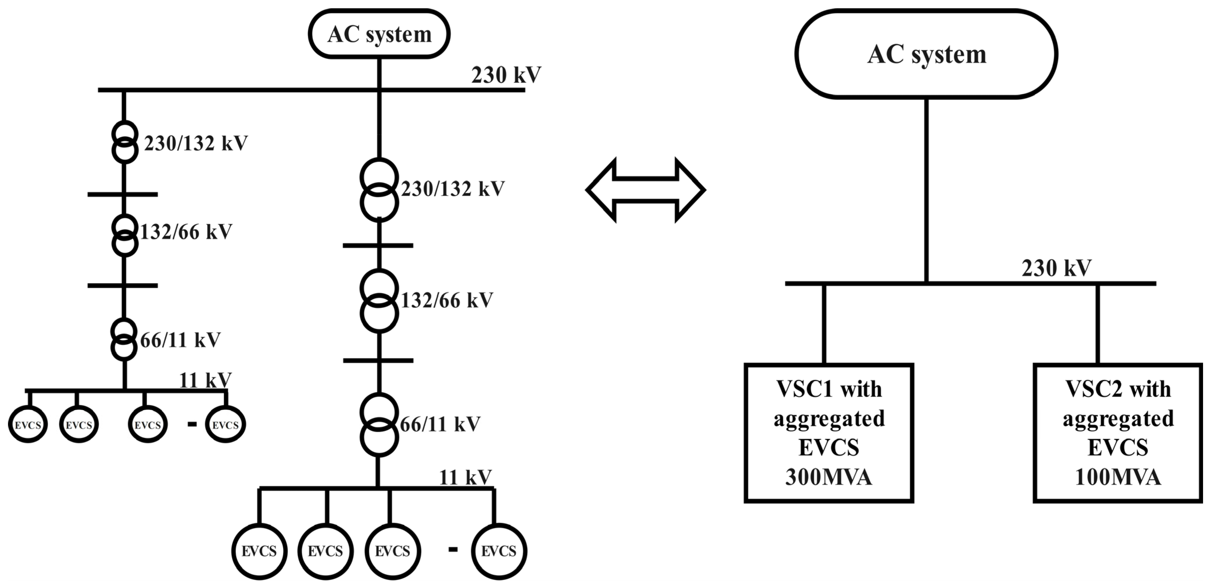
Extensive simulation studies are performed with EVFCS connected to the utility grid. The EVFCS consists of a three-phase two-level Voltage Source Converter (VSC) at the first stage of power conversion which converts the three-phase AC from the grid to DC with DC bus voltage regulation and Power Factor Correction (PFC) as its objectives. The second stage of power conversion comprises multiple DABs connected to a common DC bus. The VSC DC link voltage controllers strictly regulate the DC bus voltage to 400 kV. VSC1 and VSC2 are rated at 400 MVA and 100 MVA, respectively. Rating of DC link capacitor of VSC is 300 µF. The architecture of the EVFCS is shown in Figure 1.

3. Control of Electric Vehicle Fast Charging System

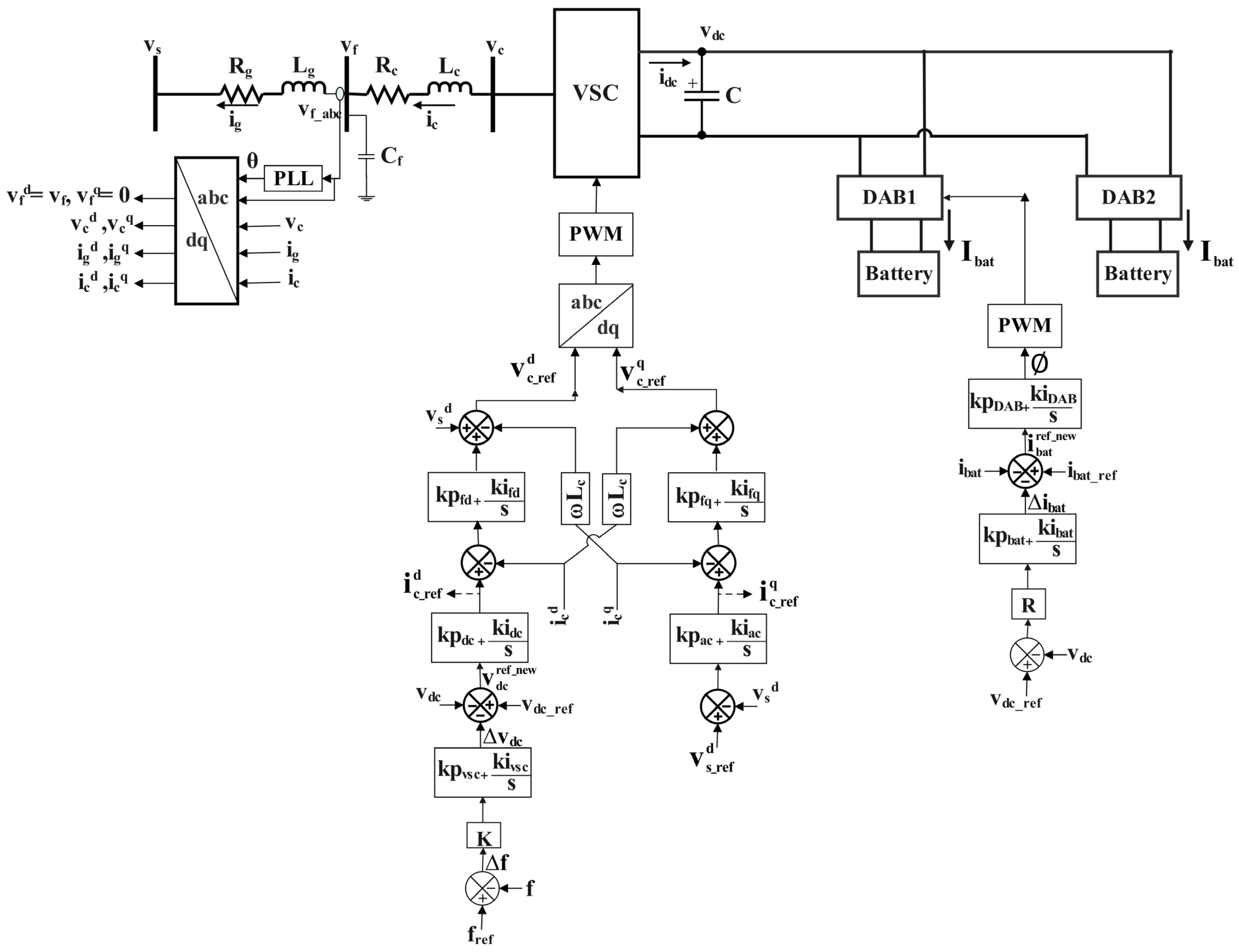
The EV Fast Charging System (EVFCS) is a two-stage power electronic conversion system with AC-DC conversion in the first stage and DC-DC conversion in the second stage. The first stage of AC-DC conversion is achieved by means of a Voltage Source Converter, which is controlled by employing the independent DQ control technique. The objectives of the VSC controllers are to regulate the common DC bus voltage and minimize the reactive power drawn by the converter. The VSC is connected to the grid by means of converter transformer and LCL filter. The second stage of DC-DC conversion is achieved by means of Dual Active Bridge (DAB) converter which is controlled by employing Phase Shift Modulation (PSM) techniques. The operation and control of the VSC and DAB are described in detail in this section. The block diagram of the EVFCS is shown in Figure 2.

3.1. Control of Grid Tied VSC

The three-phase boost rectifier is the most commonly used converter for the AC-DC power conversion stage due to its advantages such as low device count, high DC output voltage, bidirectional capability, low current stress, high efficiency and a simple control scheme. The rectifier consists of six switches arranged in three legs. The VSC is a two-level converter that can provide a bidirectional power-flow path between the DC-side voltage source and the three-phase AC system.
The firing scheme of VSC system is based on self-commutated Pulse Width Modulation (PWM) technique. The grid voltage vector is oriented along the d-axis thus independent control of real and reactive power is achieved. The component of grid voltage vector along the q-axis is zero [8]. The primary objective of DQ control is to simplify the control of AC quantities by transforming them into a two-coordinate reference frame: the direct axis (d-axis) and the quadrature axis (q-axis). This transformation, achieved through the Clarke and Park transformations, facilitates independent control of active and reactive power, contributing to the precise regulation of voltage and current in the system. The dq control strategy excels in decoupling control components, separating the d and q-axis current components for independent regulation. This decoupling feature is particularly advantageous in applications such as electric drives and renewable energy systems, where accurate control overactive and reactive power is crucial for efficient operation. In the dq frame, the Phase-Locked Loop (PLL) plays a crucial role in voltage control by ensuring that the rotating reference frame of the Park transformation is aligned with the utility grid voltage vector. This alignment is necessary for accurate control of active and reactive power flow. The PLL achieves this alignment by minimizing either the direct or quadrature axis reference voltage, which ensures that the phase angle of the rotating reference frame matches the phase angle of the utility grid voltage vector. The inner current control loop and the outer control loop are usually designed separately due to their distinct bandwidth requirements. The inner current controls require a fast response and a high bandwidth (e.g., 200 rad/s). The outer controls require a much slower response and a lower bandwidth (e.g., 5 rad/s).

3.2. Modeling of Grid Tied VSC

In the modeling of the VSC dq transformation is used where the d-axis is aligned along the a-axis which gives
v f d = v f   ;   v f q = 0  
The VSC controller diagram is given in Figure 3. The AC side of the VSC is modeled using the equations
L g n d i g n d t = v s n v f n R g n   i g n  
C f n d v f n d t = i g n i c n  
L c n d i c n d t = v f n v c n R c n   i c n  
The outer loop of the DC voltage controller is
i c _ r e f d = k p d c + k i d c s v d c _ r e f v d c  
The inner loop of the DC voltage controller is
V c _ r e f d = v f d + k p f d + k i f d s i c _ r e f d i c d + ω L c   i c q  
The d-axis voltage reference is given by
V c d = 1 1 + s T V c r e f d  
The outer loop for AC voltage controller is
i c _ r e f q = k p a c + k i a c s v f _ r e f d v f d  
The inner loop of AC voltage controller is
V c _ r e f q = k p f q + k i f q s i c r e f q i c q ω L c   i c d  
The q-axis voltage reference is given by
V c q = 1 1 + s T V c _ r e f q  
The DC capacitor voltage of the VSC is given by
C d v d c d t = i d c i b a t  
Equations (1)–(10) form the dynamic equations of the VSC and its AC side. These equations are further perturbed and linearized to organize the equations in the form of ˙ X = A X + B U . The A matrix is then subjected to eigen value analysis and using the root locus plots obtained, the gain parameters of the VSC controllers are tuned.

3.3. Control of Dual Active Bridge Converter

The second stage of power conversion in EVFCS is DC-DC conversion which is directly connected to the EV battery and hence, isolation is required. The Dual Active Bridge (DAB) Converter is the most promising topology due to the advantages it offers such as galvanic isolation, high efficiency, inherent ZVS, high voltage gain and high-power density. The modularity feature of DAB allows scaling to a higher voltage level. DAB topology consists of two active bridges (primary and secondary bridge) connected by a high-frequency isolation transformer. The power flow is controlled by varying the phase shift angle between the primary bridge and the secondary bridge of the converter. When the voltage of the primary bridge leads the voltage of the secondary bridge, power flows from the primary bridge to secondary bridge thus charging the battery. When the voltage of the primary bridge is lagging the voltage of the secondary bridge, power flows from the secondary bridge to the primary bridge thus discharging the battery. With a simple control scheme, the bidirectional power flow can be controlled. The firing pulses are at constant duty cycle of 0.5 (50%) and the phase shift between the primary and secondary bridge is controlled to regulate the power transfer. The topology of the three-phase boost rectifier and the control structure of the VSC and DAB is given in Figure 3.
The power transfer in the Dual Active Bridge (DAB) converter is given by the relation
P = V d c V b a t n 2 L f s w π 1 π
where Vdc is the DC bus voltage of the VSC
  • Vbat is the battery voltage
  • n is the transformer turns ratio
  • L is the leakage inductance of the transformer
  • is the phase shift between the two H-bridges of the DAB converter
  • f s w is the switching frequency
The power transfer in DAB converter is regulated by changing the duty ratio of the switch, phase shift between the two bridges and the switching frequency of the converter. This work considers a constant duty cycle of 50% and a constant switching frequency of 100 kHz.

4. Inertia Control Strategy

The capability of the VSC to provide frequency support by changing the real power flow into the DC system is studied. When a disturbance occurs in an electrical grid, such as a sudden increase or decrease in power demand or a fault in the system, it can have a notable impact on the grid frequency. Grid frequency is a crucial parameter that reflects the balance between electricity generation and consumption. Under normal operating conditions, the frequency is maintained at a constant level. During a disturbance, the balance between generation and consumption is momentarily disrupted, leading to frequency deviations.
If the disturbance causes an increase in power demand or a decrease in generation, the grid frequency tends to drop. Conversely, if the disturbance results in a sudden decrease in power demand or an increase in generation, the grid frequency may rise. Additionally, the integration of renewable energy sources, which can be variable and intermittent, adds complexity to grid frequency control. Grid operators use sophisticated control systems to balance supply and demand and maintain grid frequency within acceptable limits. Overall, maintaining a stable grid frequency is essential for the reliable and secure operation of the electrical power system. The use of Voltage Source Converters in EV charging systems allows for greater flexibility, control, and efficiency in managing the power flow between the grid, renewable energy sources, and Electric Vehicles. The EVs are modeled to operate both in G2V mode and V2G mode. The droop control implemented in the EVFCS for virtual inertia support is shown in Figure 4. k p v , k i v , k p d and k i d are the proportional and integral gain parameters of the VSC and DAB, respectively. The subscripts v and d denote VSC and DAB, respectively.
The I-f droop coefficients of the battery charging ports are given as
R 1 = I b a t 1 V D C 1
R 2 = I b a t 2 V D C 2
where R1 and R2 are the droop coefficients of the charging ports connected to VSC1 and VSC2, respectively.
The I–V droop coefficients K1 and K2 of the charging system are given as
K 1 = V D C 1 f
K 2 = V D C 2 f
In this work, the inertia support offered by the EVFCS is studied by exploring various operating modes of the system. The operating modes that are considered are
  • Single droop control-G2V mode
  • Single droop control-V2G mode
  • Dual droop Control Mode
  • Grid-forming mode
  • Augmented Frequency Support Mode

4.1. Single Droop Control-G2V Mode

Sequentially dissipating the energy stored in the EV charging system in a coordinated manner is the objective of the proposed controller. Inertia of the VSC integrated DAB system consists of HVSC and HDAB. The inertial support offered by VSC controls is named as HVSC and the inertial support given by DAB controls is named as HDAB.
After the onset of frequency excursions, the battery current references are reduced due to the action of controllers. The frequency error manifests as change in the battery current reference setting. This signal is fed as a modulating signal to the PI controller which gives the required phase shift for tracking the battery current references. In this paper, deployment of HDAB during both G2V and V2G mode is named as single droop control. As multiple DAB converters are connected to the common DC bus connected to VSC1 and VSC 2, there is a need for coordinated support of DAB converters. Irrespective of charging speed preferences and SOC of the battery droop coefficients R proposed in this paper for DAB converter.
R = I D A B f
Considering all DAB converters are connected to EV loads
R = I b a t f
VSC1 and VSC2 are rated at 400 MVA and 100 MVA, respectively. The support offered by VSC is shared proportional to their individual ratings. Droop settings are deployed for proportional sharing among the converters. Frequency error signal passes through a droop constant block which is fed to the PI controller. The output of PI controller yields ΔIbat, a modulating signal. Modulating signal ΔIbat further modulates the current references of the battery.
I b a t r e f = I b a t r e f + R 1 f r e f f m e a s
V d c r e f = V d c r e f + K 1 I b a t r e f I b a t
Battery current reference is given to cascaded PI controller further gives the reference phase shift which is subsequently realized by analog circuitry and fed to the DAB converter switches. The gain parameters of all the PI controllers are given as tabulation in the next section.
In single droop control-G2V mode, on the detection of a frequency dip, the control reduces the DC current output of the VSC, thus reducing the DC power output since the DC voltage is maintained the same. This is reflected on the AC power absorbed by the VSCs. The reduction in the AC power absorbed by the VSCs aid in meeting out the additional load and improves the system frequency. The VSCs continue to operate in DC link voltage control mode, where the DC voltage, Vdc is not modulated. The DC current reference of the VSCs are modulated as
I b a t r e f n e w = I b a t r e f o l d Δ I b a t Δ f Δ f  

4.2. Single Droop Control-V2G Mode

The mode of operation of EVFCS is switched from G2V to V2G when the frequency deviation is large and the support from the single droop control (G2V) mode is insufficient to stabilize the grid frequency. Wherever possible, the mode is changed from G2V to V2G to pump the stored power into the grid. The inertial support HDAB is utilized to stabilize the grid frequency.
Single droop control-V2G mode is similar to G2V mode, except when the additional load added exceeds the total power drawn by the VSCs. When the load is greater than the sum of the powers drawn by the VSCs from the AC grid, reducing the DC current reference of the VSCs will not provide significant support to improve the system frequency. Hence, the mode is changed from G2V to V2G mode based on user preference. The DC currents of the VSCs are reversed and the VSCs are made to operate in inverter mode supplying power to the AC grid to mitigate the frequency dip. The DC voltage reference of the VSCs are not modulated. The DC current reference of the VSCs is:
I b a t r e f n e w = I b a t r e f o l d Δ I b a t Δ f Δ f  
The product of the droop coefficient and the frequency error is greater than the steady-state DC current reference of the VSCs, which makes the new DC current reference negative. Negative DC current indicates the reversal in the power flow direction and influences the VSCs to act as inverters, by freewheeling the energy stored in the battery through the VSCs. This additional power helps improve the system frequency.

4.3. Dual Droop Control

In dual droop control mode, the energy stored in the DC capacitor of the VSCs is extracted in addition to the reduction in battery charging current. This mode utilizes a cascaded control loop. In the outer loop, the change in DC voltage reference is given by the product of frequency error and the voltage droop constant, K where K =   Δ V d c Δ f .
V d c r e f = V d c + Δ V d c Δ f Δ f  
The battery charging current is modified depending upon the change in the DC voltage reference. In the inner loop, the amount of battery current to be modified is given by the product of the current droop constant, R where R = Δ I b a t Δ V d c .
I b a t r e f = I b a t + Δ I b a t Δ V d c Δ V d c  
Individual battery currents are modulated based on individual DAB and converter ratings, respectively. The inner loop, which modifies the battery charging current, is faster than the outer loop, which modifies the DC voltage reference. By the combined action of the slow and fast controllers, dual droop control scheme can provide inertia support to both momentary inertia support requirements as well as prolonged inertia support for stable operation of the system.

4.4. Grid-Forming Mode

In grid-forming (GFM) mode, both the VSC are switched from Grid Following (GFL) mode to grid-forming mode and are made to act similar to a VSG. They behave like a voltage source. The impact of grid conditions is highly significant in the operation of the grid following converters. Whereas the grid-forming converters which act as a voltage source aid in maintaining the voltage and frequency, even during the presence of disturbances. They emulate the kinetic energy of a Synchronous Generator’s rotating mass and provide virtual inertia. This virtual inertia slows down the Rate of Change of Frequency (RoCoF) during any disturbance, thus preventing rapid frequency drops that could lead to widespread blackouts and hence significantly enhances the stability of the system.
P a c r e f = P a c + K p   Δ ω  
The P-f droop characteristics share real power proportional to frequency deviation, thereby stabilizing the system frequency. This linear relationship is given by
f = f 0 m P P 0
where f is the measured frequency
  • f0 is the nominal frequency
  • P is the measure power at the given time instant
  • P0 is the Active power reference
  • m is the droop coefficient
  • m is the sensitivity factor relating to frequency and active power. If m increases, the change in frequency increases for a given change in power.

4.5. Augmented Frequency Support

When the frequency dip is larger, the operation shifts to Augmented Frequency Support (AFS) mode when there is no support for V2G mode. Still, the front-end VSC can offer inertia support. In this mode, the DABs are not isolated from the DC bus of VSC. DAB controls are made to shift to idle mode where the EVs are charged from the ESS. The Augmented controller modulates the DC bus voltage reference of the VSC. The DC bus voltage reference is modulated by a signal namely ΔVdc, which is the required inertial support from the HVSC. As all grid tied VSC’s deployed in DC fast charging applications, routinely regulates, Vdc,ref the action of Augmented controller manifests as dip in the DC bus voltage. The inertia is extracted from the VSC to offer inertia support, and the charging goes to an idle state.
The DC voltage reference is modulated as
V d c r e f = V d c + Δ V d c Δ f Δ f  
Grid-tied VSCs which feed the Charging stations share power proportionally based on droop coefficients. The charging station ESS and EV’s opting to participate in frequency support act as distributed slack converters to maintain DC bus voltage on VSC side.
  • In this mode I E S S = I b a t
Δ I b a t Δ V d c = R v  
wherein R v = f S O C , C b a t , H E V , H E S S
This mode is more stable as VSC side and DAB side controllers are almost decoupled. This control scheme offers superior frequency support at the expense of DC bus voltage reduction, and this mode has to be revoked following frequency nadir. Table 1 briefs about the various control schemes simulated and compared in this study.

5. Results and Discussion

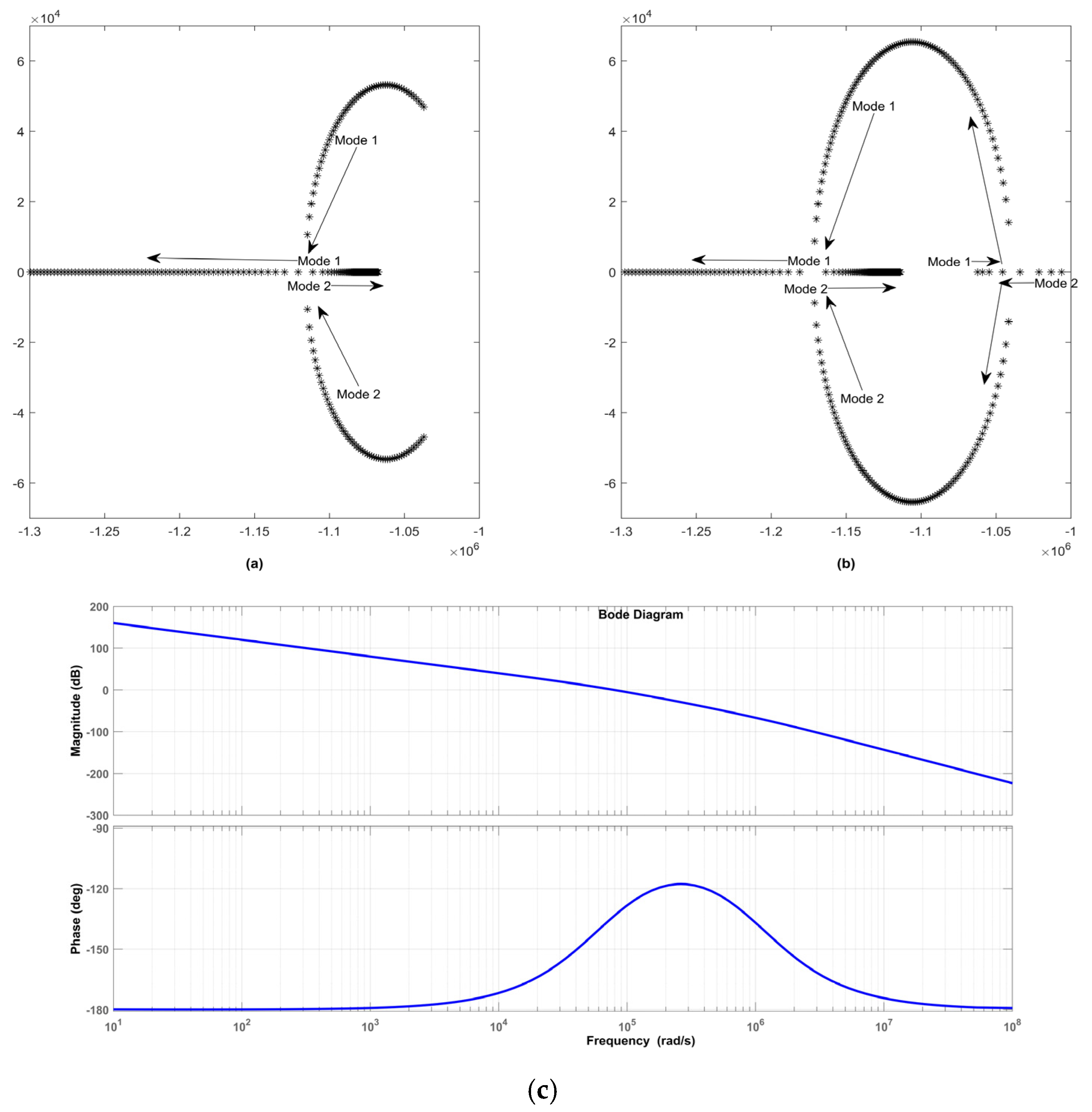
The simulation of the EVFCS to provide inertia support to the grid is performed using PSCAD/EMTDC. The system parameters considered for the simulation study are given in Table 2. The EVFCS is connected to the AC grid at 420 kV, 50 Hz. The VSC is connected to the grid by means of a converter transformer and LCL filter. The VSC1 is rated 400 MVA and the VSC2 is rated 100 MVA. Both the converters are operating in rectifier mode. Initially, both the VSCs act as individual slack converters, which control the DC voltage of the VSCs. The control objective of the VSC controllers is to regulate the DC bus voltage to 400 kV at normal operating conditions. Under disturbance conditions, the VSC controllers are designed to operate at new steady-state conditions as dictated by the control. The frequency disturbance is created by the addition of loads at the bus. The VSC controllers are designed to share the inertial response in proportion to their individual MVA ratings. The gain parameters of the VSC are tuned with the help of root locus plots. Figure 5 depicts the root locus for the parameter perturbations of the gain parameters.
In Figure 5c, the bode plots shows the frequency response by perturbing the input Δf and plotting Δ V d c . Since the phase remains below −90 degrees and does not enter an unstable region, the system is stable. This response plot is typical for feedback systems that need high gain at low frequencies. The phase peak around the crossover frequency reflects the combined effects of controller constants shaping phase margin for stability. The overall shape indicates that the controller parameters are tuned to balance a stable response with sufficient phase margin.
The performance of our proposed strategy is compared with the existing frequency support schemes for the same load addition condition. The load is added at 3 s and removed at 4.5 s at the AC grid. When an additional load is added during the steady-state operation of the system, the frequency dips proportional to the amount of load added. The frequency support provided by the VSC and the DAB under various frequency control schemes is studied. The different schemes are listed below.

5.1. Single Droop Control

5.1.1. G2V Mode

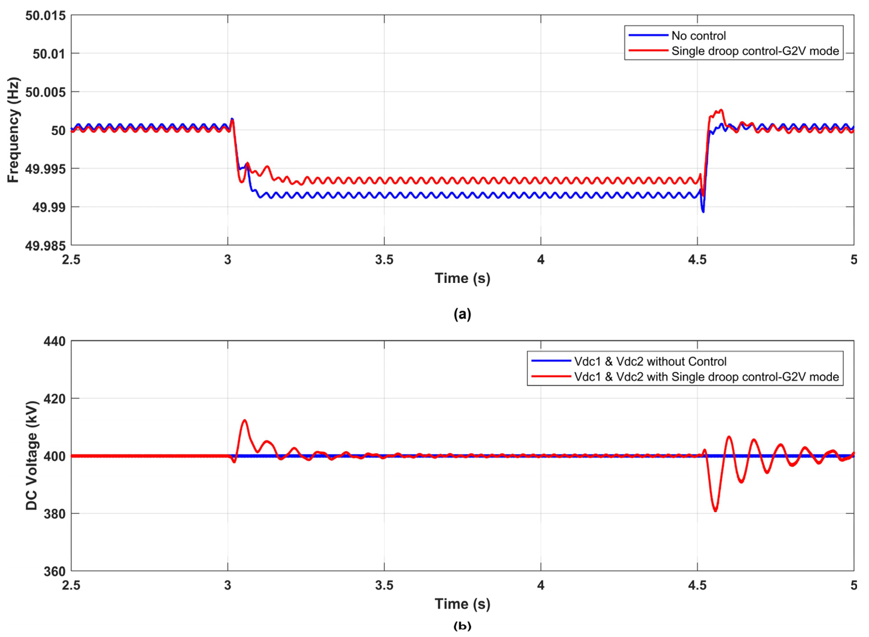
Figure 6 depicts the system frequency and the DC voltage of VSCs when a balanced load of 150 MW/phase is added at 3 s. The performance of the system with single droop control-G2V mode is compared with the case when there is no inertia support is provided.
Vdc oscillation pertaining to the DC bus voltages of VSC1 and VSC2 are shown in Figure 6b. The DC bus voltage oscillates when the inertial support is provided at 3 s or withdrawn at 4.5 s and it stabilizes due to the control action of the VSC DC link voltage controller which strictly regulates the DC bus voltage to 400 kV. When the load addition does not exceed the total power drawn by the system, single droop control-G2V mode can be effectively used to provide frequency support to the system. In this mode, the performance of the VSC is not hampered. The DC current references are reduced in proportion to their individual ratings. The additional load is supplied by reducing the power drawn by the VSCs from the grid.
The DC current from VSC 1 is shown in Figure 7a, reduces from 0.66 kA to 0.22 kA to provide frequency support. The DC current from VSC 2 is shown in Figure 7b, and it reduces from 0.16 kA to 0.07 kA. Power drawn by multiple DAB converters from VSC 1 is reduced from 268 MW to 97 MW as seen in Figure 7c. Power drawn by multiple DAB converters from VSC 2 is reduced from 68 MW to 21 MW as shown in Figure 7d. Without droop controllers, it is observed that there is no proportional sharing among VSCs.

5.1.2. V2G Mode

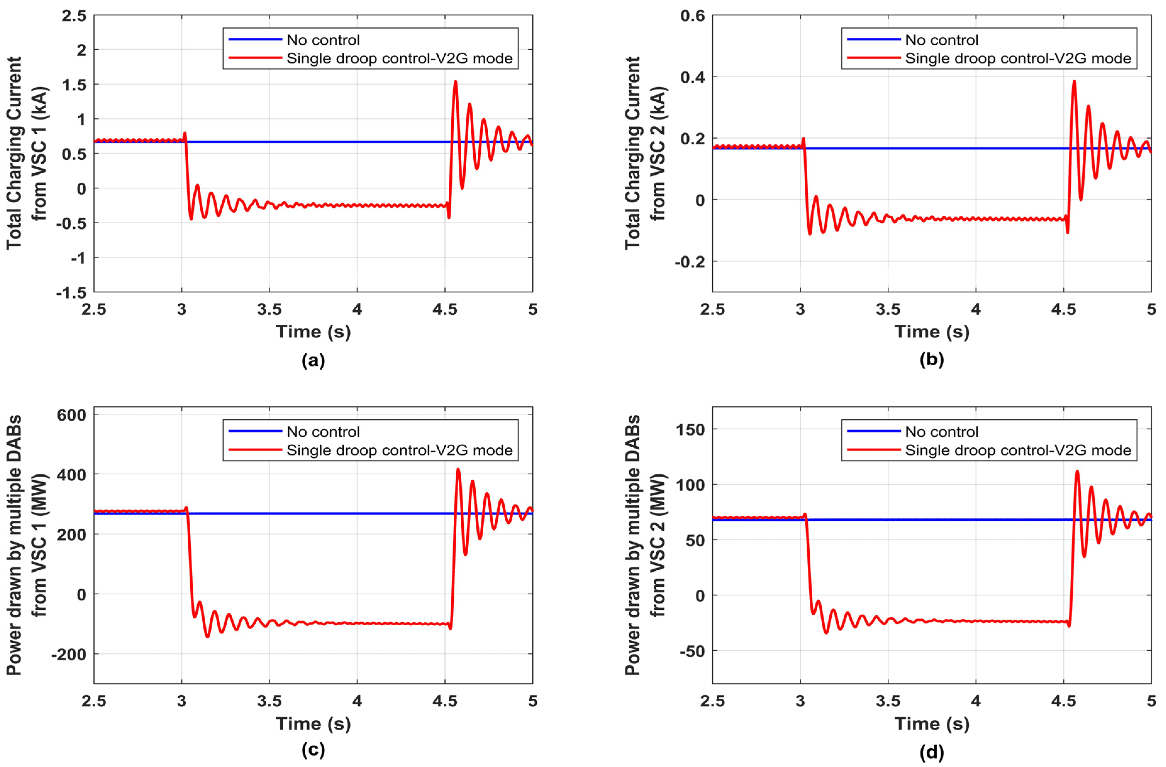
Figure 8 shows the dip in the frequency during load addition at 3 s and the DC voltage of the VSCs with single droop control-V2G mode and without control cases. The VSCs acting as inverters depends on the consumer’s preference to participate in the frequency support. Figure 9 depicts the DC currents and the DC power drawn by the VSCs, respectively. It can be observed that, when large loads are added, the DC currents and the powers of the VSCs become negative, indicating power flow from the VSCs to the AC grid which is opposite to the steady-state condition.
The DC current from VSC 1 is shown in Figure 9a, reduces from 0.66 kA to −0.25 kA to provide frequency support. The DC current from VSC 2 is shown in Figure 9b, and it reduces from 0.16 kA to −0.06 kA. Power drawn by multiple DAB converters from VSC 1 is reduced from 268 MW to −101 MW as seen in Figure 9c. Power drawn by multiple DAB converters from VSC 2 is reduced from 68 MW to −24 MW as shown in Figure 9d. Following load removal, the pre-fault battery current references are tracked and thus there is a mode shift again from V2G to G2V.

5.2. Grid-Forming Mode

Figure 10 depicts the frequency, DC voltage, charging currents and power drawn by multiple DABs, respectively.

5.3. Augmented Frequency Support

EV aggregators at charging stations are designed to meet the net EV load, minimizing the current drawn from the DC link capacitor of VSC, thus maximizing the frequency support. DC bus voltage references are reduced to improve the frequency during peak demand. In effect, the active power is released to the grid from VSC DC bus. Thus, DC grid inertia is reduced to offer AC grid frequency support. This is named as Augmented Frequency Support.
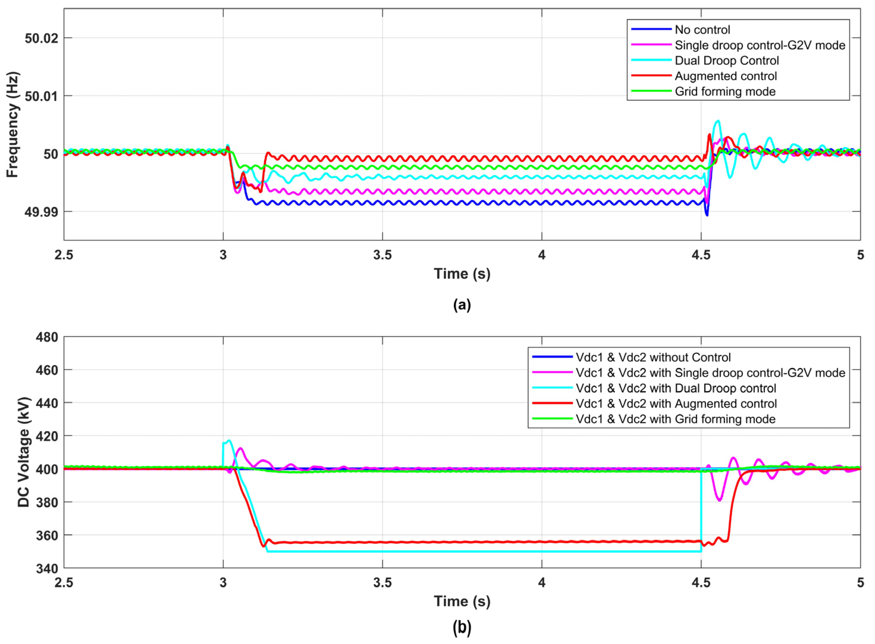
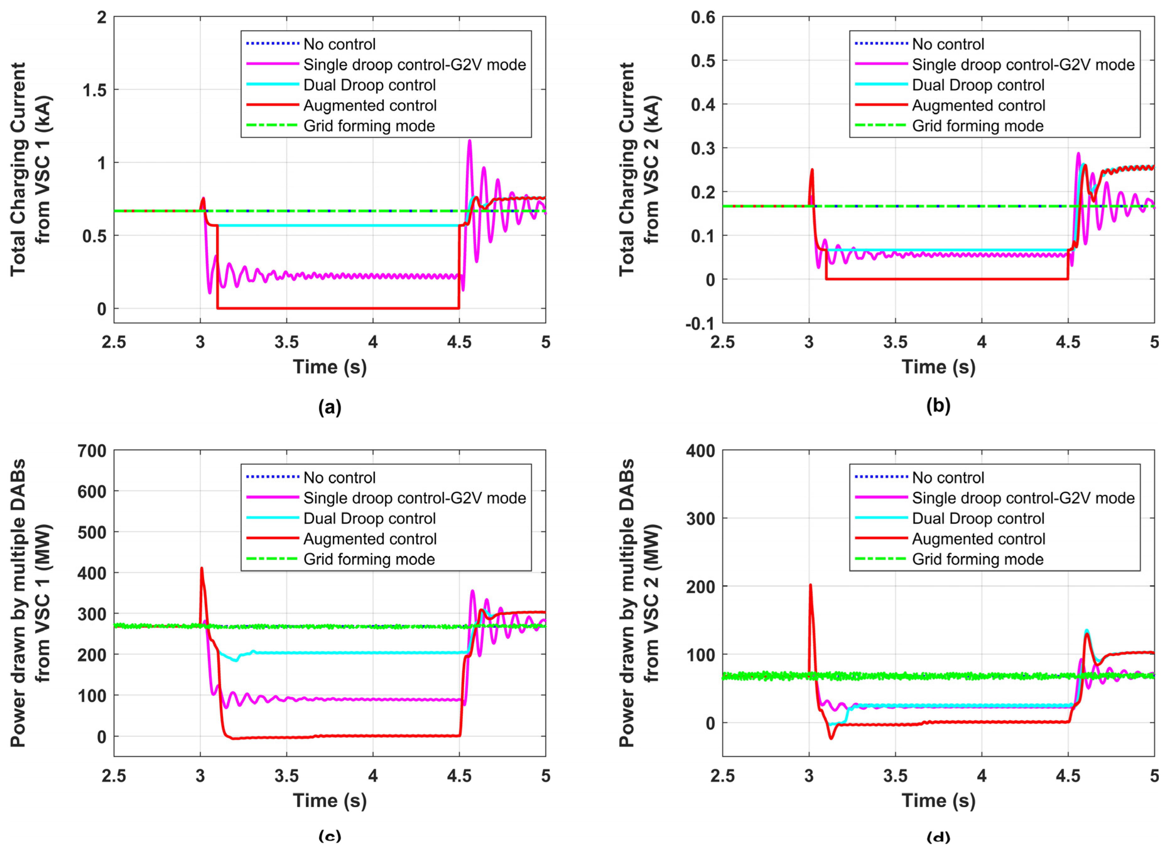
Grid frequency disturbance is initiated at t = 3 s as shown in Figure 11a. Following frequency dip, four different cases (a) single droop control-G2V mode; (b) dual droop control; (c) grid-forming mode and (d) AFS control are compared in Figure 11 and Figure 12. In dual droop control, both Vdc_ref and charging currents are reduced proportional to individual converter ratings as per droop law given in Equations (1) and (2). Augmented Frequency Support gives the maximum support as charging currents are made to zero as well. The frequency support provided by the proposed control scheme is further enhanced by comparing it with single droop control-G2V mode, dual droop control mode and grid-forming mode. The drop in charging currents is shown in Figure 12a,b. The reduction in power is seen in Figure 12c,d.

5.4. Real-Time Digital Simulation of AFS

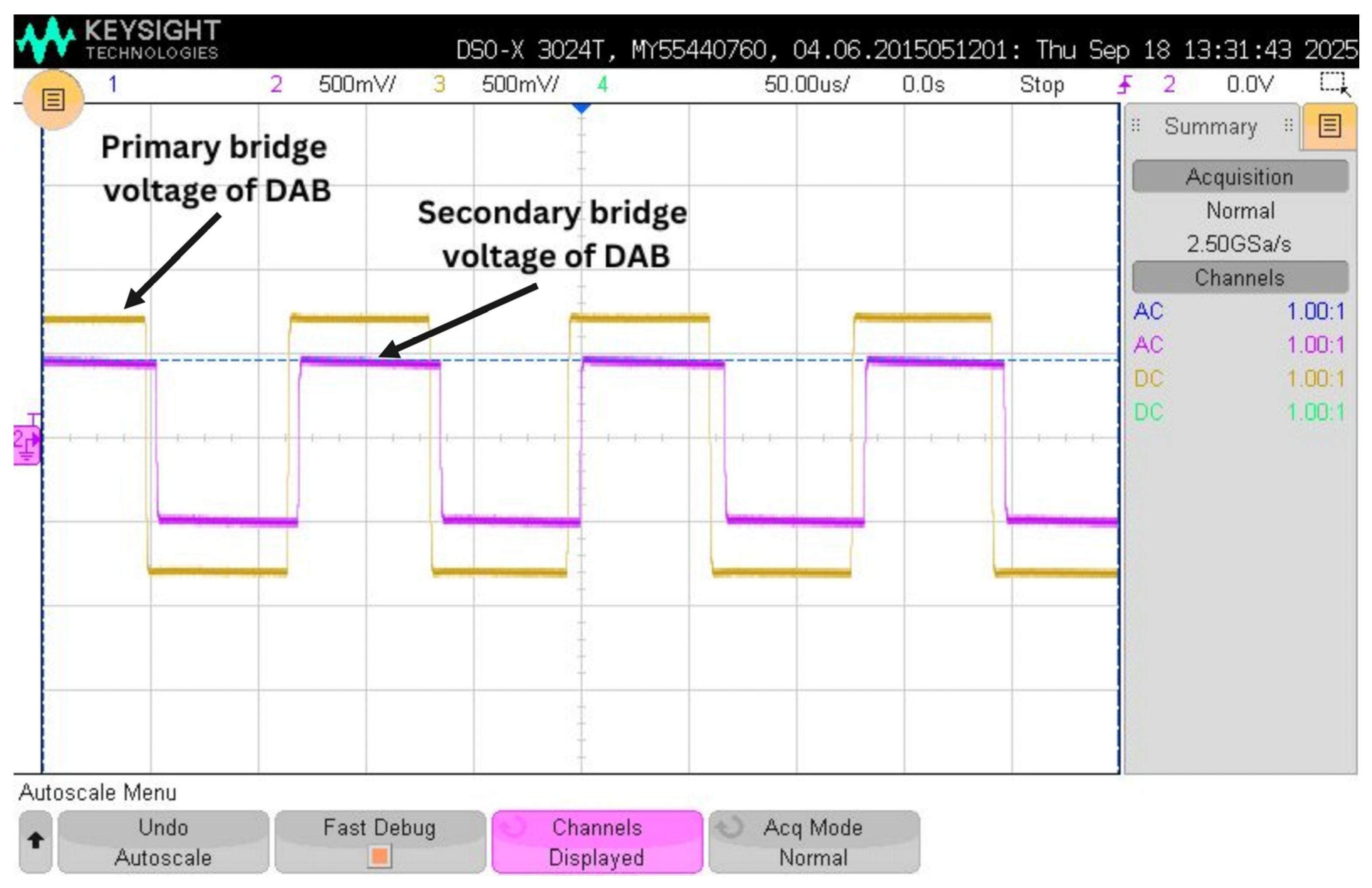
Experimental validation is performed using OP4610 Real-Time Digital Simulator (OPAL–RT Technologies, Bengaluru, India). The studied system is built in the RTDS. The OP4610 is a powerful Hardware-In-the-Loop (HIL) platform that uses a high-performance processor and an FPGA to accurately simulate power electronics systems in real time. The VSC, DAB Converters along with the grid and the controllers are built in OP4610. The plots of the VSC DC bus voltage and battery current are shown in Figure 13. It can be seen that when the modulating signal comes following a frequency dip, the VSC DC bus voltage and the battery current are reduced. The real-time results show that the control actions are effectively coordinated such that the frequency regulation is achieved. The battery plot confirms the dynamic behavior of the battery during frequency disturbance conditions. Seamless transition in the battery currents enables quick transition between various operating modes to provide frequency support. The primary and secondary side bridge voltages of the DAB converter are shown in Figure 14. The phase shift between the bridges is the cause for the power flow. When the battery current reference is modulated, the phase shift between the bridges varies.

6. Conclusions

The increasing integration of IBRs into the power system poses a significant challenge in grid operation. In this paper sequential dissipation of inertial energy stored in EV Fast Charging systems (EVFCS) is explored to provide inertia support to the power system. At the onset of frequency reduction, the aggregated DAB converter current references are reduced proportional to the individual ratings, which is followed by the DC bus voltage reference modulation. The response speeds of VSC and DAB converter controllers are coordinated to give droop-based proportional frequency support. In case of Augmented Frequency Support (AFS) mode, EV aggregators at charging stations are designed to meet the net EV load, minimizing the current drawn from the DC link capacitor of VSC, thus maximizing the frequency support. Proposed Augmented Frequency Support method is found to be superior for frequency regulation when compared to various other methods. The simulations show that the Augmented Frequency Support method yields superior mitigation of frequency deviations in the grid.

Author Contributions

Conceptualization, N.T.S., A.S.V., B.R. and K.D.R.P.; methodology, N.T.S., A.S.V. and B.R.; software, N.T.S. and B.R.; supervision, A.S.V. and K.D.R.P.; validation, A.S.V. and K.D.R.P.; writing—original draft, N.T.S., A.S.V. and B.R.; writing—review and editing, N.T.S., A.S.V. and B.R. All authors have read and agreed to the published version of the manuscript.

Funding

This research received no external funding.

Institutional Review Board Statement

Not applicable.

Informed Consent Statement

Not applicable.

Data Availability Statement

Data is contained within the article.

Conflicts of Interest

The authors declare no conflicts of interest.

Abbreviations

The following abbreviations are used in this manuscript:
DABDual Active Bridge
IBRInverter-Based Resource
EVFCSElectric Vehicle Fast Charging System
VSCVoltage Source Converter
PIProportional Integral
AFSAugmented Frequency Support
ESSEnergy Storage Systems
EVElectric Vehicle
G2VGrid to Vehicle
V2GVehicle to Grid
ZVSZero Voltage Switching
SPSSingle Phase Shift
PFCPower Factor Correction
SSTSolid State Transformer
ROCOFRate of Change of Frequency
SGSynchronous Generator

References

  1. Castro, L.M.; Acha, E. On the Provision of Frequency Regulation in Low Inertia AC Grids Using HVDC Systems. IEEE Trans. Smart Grid 2016, 7, 2680–2690. [Google Scholar] [CrossRef]
  2. Bevrani, H.; Ghosh, A.; Ledwich, G. Renewable energy sources and frequency regulation: Survey and new perspectives. IET 2010, 4, 438–457. [Google Scholar] [CrossRef]
  3. Dreidy, M.; Mokhlis, H.; Mekhilef, S. Inertia response and frequency control techniques for renewable energy sources: A review. Sustain. Energy Rev. 2017, 69, 144–155. [Google Scholar] [CrossRef]
  4. Bevrani, H.; Golpira, H.; Messina, A.R.; Hatziargyriou, N.; Milano, F.; Ise, T. Power system frequency control: An updated review of current solutions and new challenges. Electr. Power Syst. Res. 2021, 194, 107114. [Google Scholar] [CrossRef]
  5. Akram, U.; Nadarajah, M.; Shah, R.; Milano, F. A review on rapid responsive energy storage technologies for frequency regulation in modern power systems. Renew. Sustain. Energy Rev. 2020, 120, 109626. [Google Scholar] [CrossRef]
  6. Hussain, M.T.; Sulaiman, N.B.; Hussain, M.S.; Jabir, M. Optimal management strategies to solve issues of grid having electric vehicles (EV): A review. J. Energy Storage 2021, 33, 102114. [Google Scholar] [CrossRef]
  7. Tomic, J.; Kempton, W. Using fleets of electric-drive vehicles for grid support. J. Power Sources 2007, 168, 459–468. [Google Scholar] [CrossRef]
  8. Negri, S.; Tironi, E.; Danna, D.S. Integrated control strategy for islanded operation in smart grids: Virtual inertia and ancillary services. IEEE Trans. Ind. Appl. 2019, 55, 2401–2411. [Google Scholar] [CrossRef]
  9. Jafari, H.; Moghaddami, M.; Olowu, T.O.; Sarwat, A.I.; Mahmoudi, M. Virtual inertia-based multipower level controller for inductive electric vehicle charging systems. IEEE J. Emerg. Sel. Top. Power Electron. 2020, 9, 7369–7382. [Google Scholar] [CrossRef]
  10. Sockeel, N.; Gafford, J.; Papari, B.; Mazzola, M. Virtual inertia emulator-based model predictive control for grid frequency regulation considering high penetration of inverter-based energy storage system. IEEE Trans. Sustain. Energy 2020, 11, 2932–2939. [Google Scholar] [CrossRef]
  11. Lu, D.; Hu, D.; Wang, J.; Wei, W.; Zhang, X. A Data-Driven Vehicle Speed Prediction Transfer Learning Method with Improved Adaptability Across Working Conditions for Intelligent Fuel Cell Vehicle. IEEE Trans. Intell. Transp. Syst. 2025, 26, 10881–10891. [Google Scholar] [CrossRef]
  12. Heo, J.; Chang, S. Optimal planning for electric vehicle fast charging stations placements in a city scale using an advantage actor-critic deep reinforcement learning and geospatial analysis. Sustain. Cities Soc. 2024, 113, 105567. [Google Scholar] [CrossRef]
  13. Jamroen, C.; Dechanupapritta, S. Coordinated control of battery energy storage system and plug-in electric vehicles for frequency regulation in smart grid. In Proceedings of the 2019 IEEE PES GTD Grand International Conference and Exposition Asia (GTD Asia), Bangkok, Thailand, 19–23 March 2019; p. 286291. [Google Scholar] [CrossRef]
  14. Zhu, X.; Xia, M.; Chiang, H.-D. Coordinated sectional droop charging control for EV aggregator enhancing frequency stability of microgrid with high penetration of renewable energy sources. Appl. Energy 2018, 210, 936943. [Google Scholar] [CrossRef]
  15. Kheraluwala, M.N.; Gascoigne, R.W.; Divan, D.M.; Baumann, E.D. Performance characterization of a high-power dual active bridge DC-to-DC converter. IEEE Trans. Ind. Appl. 1992, 28, 1294–1301. [Google Scholar] [CrossRef]
  16. Xiong, L.; Liu, X.; Zhang, D.; Liu, Y. Rapid Power Compensation-Based Frequency Response Strategy for Low-Inertia Power Systems. IEEE J. Emerg. Sel. Top. Power Electron. 2021, 9, 4500–4513. [Google Scholar] [CrossRef]
  17. Peng, Q.; Yang, Y.; Liu, T.; Blaabjerg, F. Coordination of virtual inertia control and frequency damping in PV systems for optimal frequency support. CPSS Trans. Power Electron. Appl. 2020, 5, 305–316. [Google Scholar] [CrossRef]
  18. Ke, S.; Yang, J.; Lu, Z.; Fan, P.; Peng, X.; Chen, L.; Qian, B.; Zhang, F. Consistency Collaboration Control Strategy Based on Adaptive Virtual Inertia in Multiple Charging Stations. IEEE Trans. Energy Convers. 2024, 39, 896–913. [Google Scholar] [CrossRef]
  19. Kaur, K.; Kumar, N.; Singh, M. Coordinated Power Control of Electric Vehicles for Grid Frequency Support: MILP-Based Hierarchical Control Design. IEEE Trans. Smart Grid 2019, 10, 3364–3373. [Google Scholar] [CrossRef]
  20. Ghatuari, I.; Kumar, N.S. A Coordinated Control Strategy of Electric Vehicles for Frequency Control in Modern Power Grids. IEEE Access 2025, 1. [Google Scholar] [CrossRef]
  21. Bernal-Sancho, M.; Rocca, R.; Fernández-Aznar, G.; Comech, M.P.; Galán-Hernández, N. Grid Impact of Frequency Regulation Provided by V2Gs Aggregated at HV, MV, and LV Level. IEEE Access 2023, 11, 76768–76780. [Google Scholar] [CrossRef]
  22. Jie, B.; Baba, J.; Kumada, A. Contribution to V2G System Frequency Regulation by Charging/Discharging Control of Aggregated EV Group. IEEE Trans. Ind. Appl. 2024, 60, 1129–1140. [Google Scholar] [CrossRef]
  23. Zheng, L.; Marellapudi, A.; Chowdhury, V.R.; Bilakanti, N.; Kandula, R.P.; Saeedifard, M.; Grijalva, S.; Divan, D. Solid-State Transformer and Hybrid Transformer with Integrated Energy Storage in Active Distribution Grids: Technical and Economic Comparison, Dispatch, and Control. IEEE J. Emerg. Sel. Top. Power Electron. 2022, 10, 3771–3787. [Google Scholar] [CrossRef]
  24. Paucara, J.D.; Peña, J.C.U.; Rosas, D.S.Y. HESS Management for Virtual Inertia, Frequency, and Voltage Support Through Off-Board EV Bidirectional Chargers. IEEE Open J. Ind. Electron. Soc. 2024, 5, 376–385. [Google Scholar] [CrossRef]
  25. Kazemtarghi, A.; Dey, S.; Mallik, A. Optimal Utilization of Bidirectional EVs for Grid Frequency Support in Power Systems. IEEE Trans. Power Deliv. 2023, 38, 998–1010. [Google Scholar] [CrossRef]
  26. Yilmaz, M.; Krein, P.T. Review of the Impact of Vehicle-to-Grid Technologies on Distribution Systems and Utility Interfaces. IEEE Trans. Power Electron. 2013, 28, 5673–5689. [Google Scholar] [CrossRef]
  27. Sharida, A.; Bayindir, A.B.; Bayhan, S.; Abu-Rub, H. Hierarchical Control of DC Coupled Fast EV Charging Station. IEEE Trans. Power Electron. 2025, 40, 11690–11700. [Google Scholar] [CrossRef]
  28. Lin, G.; Liu, J.; Rehtanz, C.; Li, C.; Li, Y.; Wang, P. Inertia Droop Control and Stability Mechanism Analysis of Energy Storage Systems for DC-Busbar Electric Vehicle Charging Station. IEEE Trans. Transp. Electrif. 2023, 9, 266–282. [Google Scholar] [CrossRef]
  29. Rana, R.; Singh, M.; Mishra, S. Design of Modified Droop Controller for Frequency Support in Microgrid Using Fleet of Electric Vehicles. IEEE Trans. Power Syst. 2017, 32, 3627–3636. [Google Scholar] [CrossRef]
  30. Anbuselvi, S.V.; Devi, R.P.K.; Brinda, R. Coordinated Control of EV Charging stations for Grid Frequency Support. In Proceedings of the 2022 International Conference on Intelligent Controller and Computing for Smart Power (ICICCSP), Hyderabad, India, 21–23 July 2022; pp. 1–6. [Google Scholar] [CrossRef]
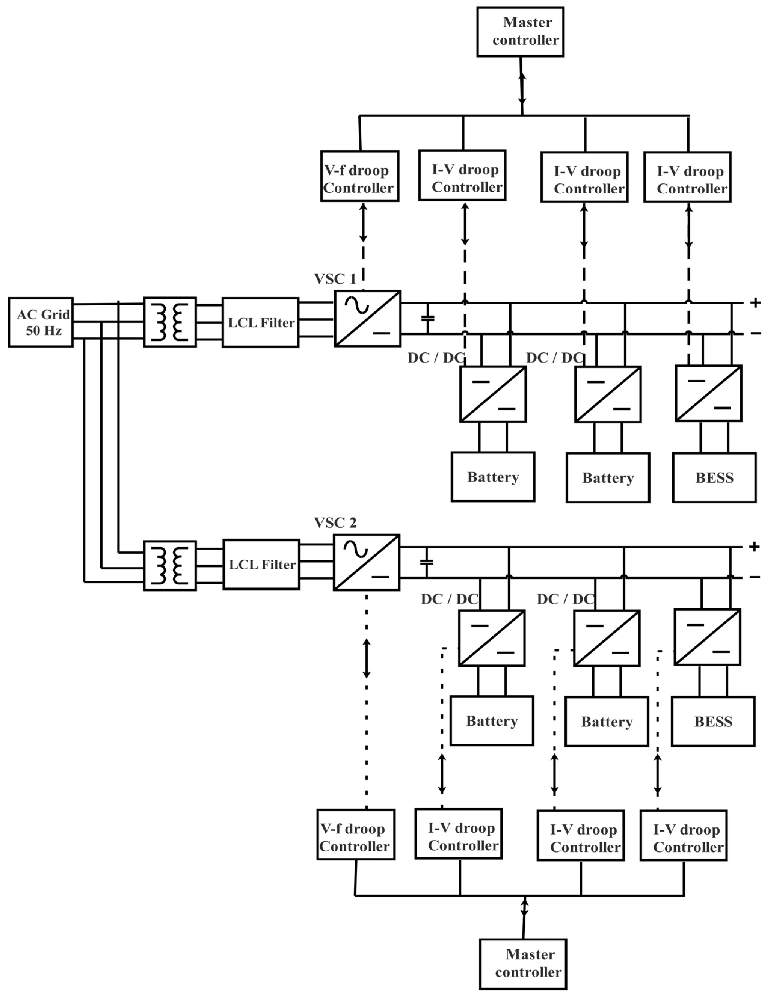
Figure 1. Electric Vehicle Fast Charging System (EVFCS) Architecture.
Sustainability 17 08997 g001
Figure 2. Block diagram of EVFCS.
Sustainability 17 08997 g002
Figure 3. Controller structure of EVFCS.
Sustainability 17 08997 g003
Figure 4. Droop control for Virtual Inertia Support.
Sustainability 17 08997 g004
Figure 5. Root locus of the gain parameters (a) k p f d and (b) k p f q . (c) Bode plot for Δ V d c / Δ f .
Sustainability 17 08997 g005
Figure 6. Single droop control-G2V mode. (a) Frequency at PCC without control and with droop control and (b) DC voltage without control and with droop control.
Sustainability 17 08997 g006
Figure 7. Single droop control-G2V mode. (a) The DC current of VSC1. (b) The DC current of VSC2 (c) The DC power of VSC1. (d) The DC power of VSC2.
Sustainability 17 08997 g007
Figure 8. Single droop control-V2G mode. (a) Frequency at PCC without control and with droop control. (b) DC voltage without control and with droop control.
Sustainability 17 08997 g008
Figure 9. Single droop control-V2G mode. (a) The DC current of VSC1. (b) The DC current of VSC2. (c) The DC power of VSC1. (d) The DC power of VSC2.
Sustainability 17 08997 g009
Figure 10. Grid-forming mode. (a) Frequency. (b) DC Voltage. (c) Charging current. (d) DC power of VSC1 and VSC2, respectively.
Sustainability 17 08997 g010
Figure 11. Comparison of various strategies. (a) Frequency. (b) DC voltage.
Sustainability 17 08997 g011
Figure 12. Comparison of various strategies. (a) The DC current of VSC1. (b) The DC current of VSC2. (c) The DC power of VSC1. (d) The DC power of VSC2.
Sustainability 17 08997 g012
Figure 13. VSC DC bus voltage and battery current.
Sustainability 17 08997 g013
Figure 14. Primary and secondary side bridge voltage of DAB converters.
Sustainability 17 08997 g014
Table 1. Various frequency support schemes and their comparison.
CaseSchemeMode of Operation of Front-End VSC/MMC and Governing EquationsMode of Operation of Front-End DAB and Governing Equations
1Single droop control (G2V mode/V2G mode)Vdc tracking without reference modulation I b a t r e f = I b a t + Δ I b a t Δ f Δ f
2Dual droop supportVdc tracking with reference modulation with K f droop
V d c r e f = V d c + Δ V d c Δ f Δ f  
I b a t r e f = I b a t + Δ I b a t Δ V d c Δ V d c
Individual battery currents are modulated based on R d c   droop. Droop based on individual DAB converter ratings
3Grid-forming modePac tracking
P a c r e f = P a c + K p Δ   ω
(P-f) droop characteristics share real power proportionally to frequency deviation, thereby stabilizing the system frequency.
None of the DC-side references are changed. Same steady-state operating condition prevails
4Augmented Frequency SupportPdc tracking
V d c r e f = V d c + Δ V d c Δ f Δ f  
Grid tied VSC’s feeding Charging stations share power proportionally based on droop coefficients.
Charging station ESS and EV’s opting to participate in frequency support act as distributed slack converters to maintain VC bus voltage on VSC side.
In this mode   I E S S = I b a t
Δ I B Δ V d c = R v
wherein R v = f S O C ,     C b a t ,   H E V   ,   H E S S
Table 2. System Parameters.
ParameterSpecification
System Frequency50 Hz
Grid Voltage420 kV
Real Power Generation350 MW
VSC 1 Power Rating400 MVA
VSC 2 Power Rating100 MVA
DC Bus Voltage400 kV
LCL filter parametersLg = 252 mH, Rg = 2.31 ohm,
Lc = 72.4 mH, Rc = 0, Cf = 5 uF
Gain parameters of VSC controller
DC Voltage controllerKp = 0.05, Ti = 1.1
AC voltage controllerKp = 10, Ti = 0.0012
Inner current controllersKp = 60, Ti = 0.0002
Droop, K10.8
Droop, K20.2
Disclaimer/Publisher’s Note: The statements, opinions and data contained in all publications are solely those of the individual author(s) and contributor(s) and not of MDPI and/or the editor(s). MDPI and/or the editor(s) disclaim responsibility for any injury to people or property resulting from any ideas, methods, instructions or products referred to in the content.