Article

Minimizing the Damage of Underground Coal Mining to a Village Through Integrating Room-and-Pillar Method with Backfilling: A Case Study in Weibei Coalfield, China

1
School of Energy Science and Engineering, Xi’an University of Science and Technology, Xi’an 710054, China
2
Shaanxi Guojiahe Coal Industry Co., Ltd., Baoji 721500, China
*
Author to whom correspondence should be addressed.
Sustainability 2025, 17(2), 602; https://doi.org/10.3390/su17020602
Submission received: 22 December 2024 / Revised: 6 January 2025 / Accepted: 9 January 2025 / Published: 14 January 2025
(This article belongs to the Section Energy Sustainability)

Abstract

The accelerating industrialization process of China expanded coal consumption and induced the depletion of resource reserves. Meanwhile, vast amounts of coal resources are “trapped” since they are located beneath buildings, railways, and water bodies, which is termed the “three-limitation” problem in China. In order to minimize the damage of coal extraction to two villages in Weibei Coalfield, China, a modified room-and-pillar method is integrated with backfilling. This work conducted a series of numerical tests in order to determine the optimal design of this integration in the Jinqiao coal mine, and field verification was carried out. The result shows that the widths of both the pillar and backfill body have an influence on the surface subsidence, but the subsidence is controlled to be within a low extent by the proposed method. Additionally, the backfill body becomes a stress concentration area, induced by the transmission of the weight of overlying strata from the gob area. Plastic failure is concentrated near the top of the backfill body and exhibits shear characteristics, while the immediate roof experiences less damage, primarily in the form of tensile failure. As the width of the backfill body decreases, the tensile and shear failures in the immediate roof gradually diminish, reducing the impact on the overlying strata. The protection of village buildings can therefore be guaranteed.

1. Introduction

Coal mining serves as the foundation for the energy industry of China. It constitutes approximately 60% of China’s energy consumption mix and therefore represents a vital resource underpinning economic development. The accelerating industrialization process has expanded coal consumption and induced the depletion of resource reserves. Meanwhile, vast amounts of coal resources are “trapped” since they are located beneath buildings, railways, and water bodies, which is termed the “three-limitation” problem in China [1,2,3]. The “three-limitation” problem posed a significant challenge to mining operations, resulting in severe resource losses and a low recovery rate [4], which profoundly threatens the survival of mining companies.
The conventional room-and-pillar method is defined as a mining system in which the mined material is extracted across a horizontal plane, creating horizontal arrays of rooms and pillars [5,6,7,8]. In China, this method is usually modified to be compatible with the widely adopted longwall systems, as shown in Figure 1. This modified room-and-pillar method (hereinafter referred to as MRP) divides a longwall panel into strips of a certain width, then mines the rooms and leaves pillars to support the roof so as to control the subsidence of the overburden. The advantages of room-and-pillar mining lie in its flexibility and strong adaptability to geological conditions, enabling the recovery of partial coal seams. By retaining coal pillars to support the overlying rock strata, it helps reduce surface subsidence and protect ground structures. However, the disadvantage of this method is that the retention of coal pillars may result in relatively low resource recovery rates, and the stability of these pillars may become an issue after long-term mining. Engineering practices have proven that the MRP can effectively reduce the settlement of overlying strata and restrict surface deformation so as to protect surface buildings [9,10]. Therefore, the MRP is one of the main methods to overcome the “three -limitation” problem. Backfill mining involves using waste materials to fill the goaf area after mining, thereby controlling roof subsidence and reducing surface deformation. Backfill mining effectively controls roof subsidence and surface deformation by using waste materials to fill the goaf area, improving resource recovery rates and reducing environmental damage. However, the cost of backfill mining may be higher, and there are certain requirements for the selection and processing of fill materials.
Analyzing the current study status of room-and-pillar mining and backfill mining both domestically and internationally reveals that with the advancement of coal mining technology in recent years, considerable achievements have been made in room-and-pillar mining and backfill mining technologies as well as their theories on strata movement. The prediction model theory has matured, and mining practices have been implemented in numerous mining areas, yielding abundant measured data [11,12,13].
However, in some cases, there are strict requirements for the surface deformation and building protections; hence, introducing the backfilling into the MRP is favorable. This integration (hereinafter referred to as RPB) takes the dual advantages of the MRP and backfilling, aiming to minimize the negative impacts of mining activities on surface buildings [14,15,16,17], as shown in Figure 2. Obviously, this idea is technically feasible, but the movements of overlying strata and the responses of the ground remain unknown. A study on PRB currently focuses only on specific aspects, lacking systematic study. This work conducted a series of numerical tests in order to determine the optimal design of RPB in Jinqiao coal mine, Heyang County, China. The characteristics of overburden structure were explored, and the effectiveness of the integrated method is validated. The outcomes can provide practical guidance for the mining operations beneath buildings.

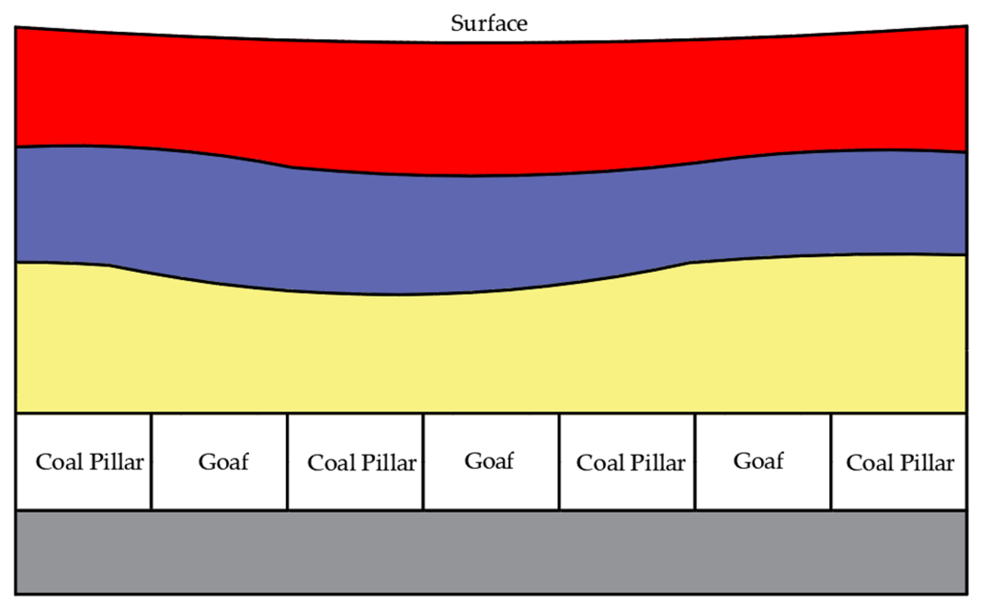
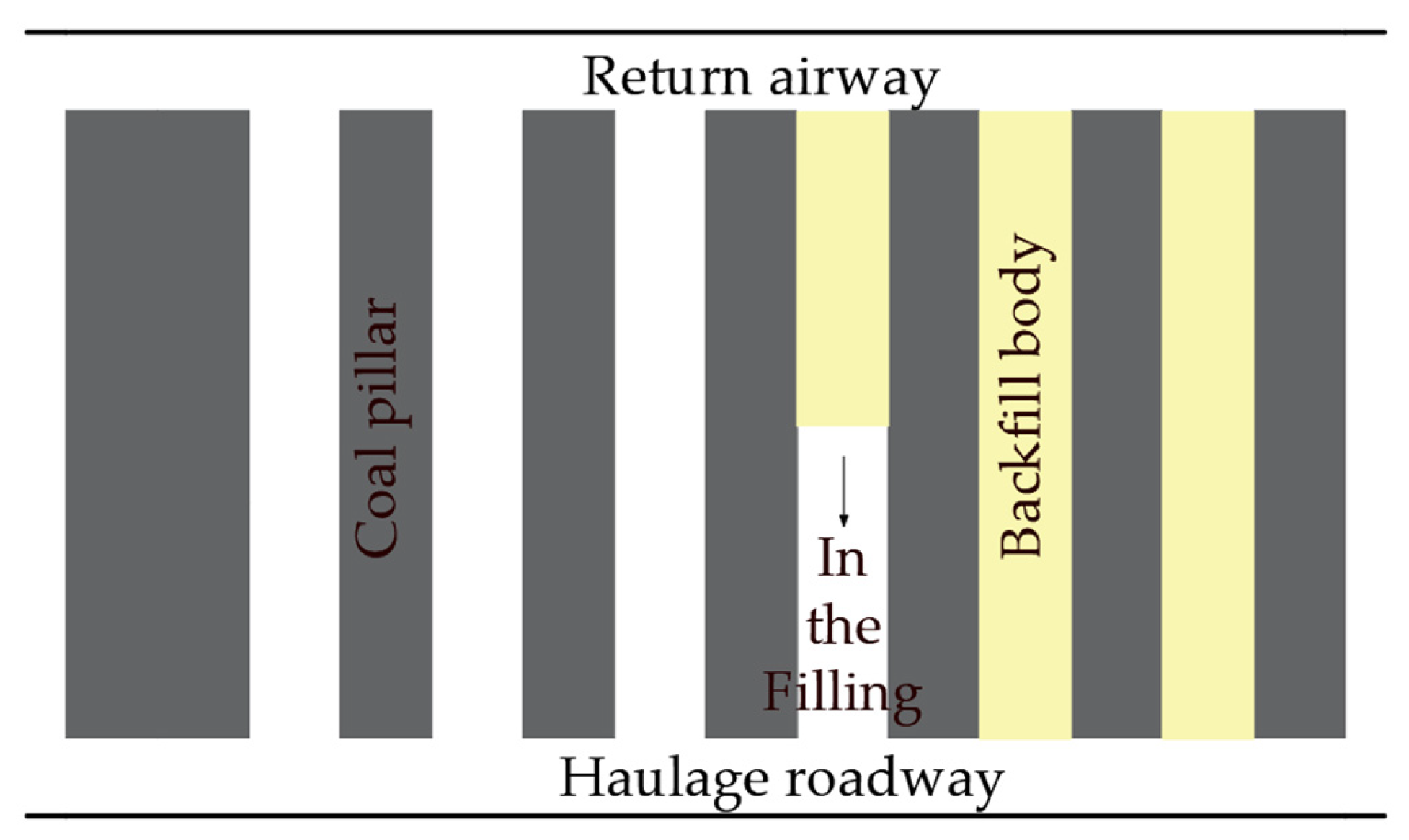
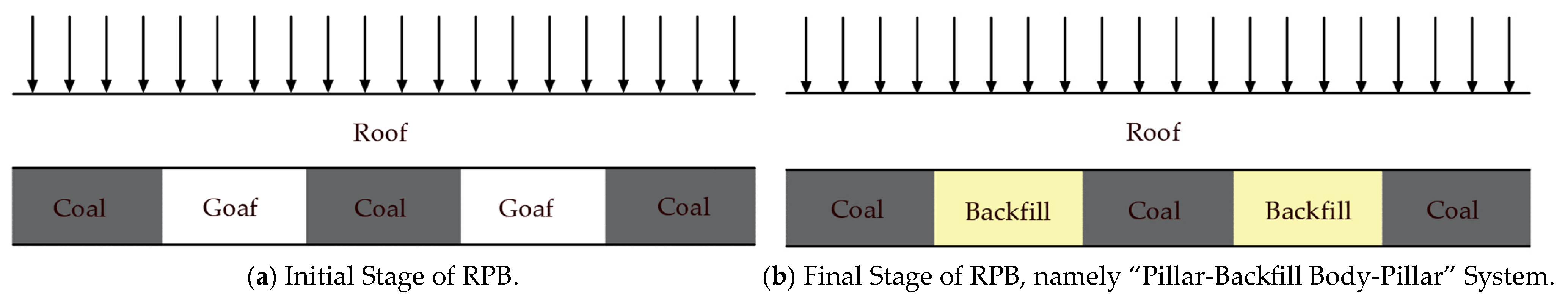
2. Ground Control Mechanism of RPB

The MRP controls the surface subsidence by retaining strip-shaped coal pillars to support the roof and prevent the collapse of overlying strata. Therefore, the widths of pillars and rooms are the key factors to maintain the stability [18,19,20]. Two principles for width calculation are proposed: (1) ensuring the lasting stability of coal pillars so that they can sustain the overburden pressure for an extended period; and (2) a favorable width of rooms needs to ensure that the surface forms a smooth, undulating-free subsidence basin after mining.
During different stages of RPB, the support structure of the roof strata undergoes transformations. Initially, the roof is supported by pillars (Figure 3a); ultimately, with the filling of material, a “pillar-backfill body-pillar” support system is formed (Figure 3b). Since the length of pillar far exceeds its width, the roof strata can be simplified as a beam structure which is supported at both ends by coal bodies. The weight of the overlying strata is transmitted to the support system through this beam. The bending and tensile characteristics of the roof are crucial for understanding the stability of rock strata in RPB.
The condition for the rock beam to reach its ultimate bending and under the action of uniformly distributed loads on top is
σ max = M W = [ σ ]
In the equation, M is the actual maximum bending moment of the rock beam, and W is the flexural section modulus of the rock beam.
In the MRP, for the supporting beam of “pillar-backfill body-pillar” system, the bending moment on any cross-section is
M = 0 l ( Q r + Q o q ) x d x
In the equation, Qr + Qo is the uniformly distributed load on the top and overlying rock layers; q is the supporting strength of the coal pillar and backfill body; and l is the length of the working face.
The definite integral of the above equation yields
M = ( Q r + Q o q ) l 2 2
For a rectangular beam with a height of h and a width of b, the flexural section modulus is
W = I z m / 2 = b h 3 / 12 m / 2 = b m 2 6 = m 2 6
In the equation, I is the neutral axis moment of inertia, and m is the thickness of the rock layer.
The critical strength condition for rock fracture is obtained by substituting M and W into the above equation:
σ max = 3 ( Q r + Q o q ) l 2 m 2 = [ σ ]
By substituting d 2 w d x 2 = M E I into the analysis, one can obtain
E I w = M = ( Q r + Q o q ) x d x
In the equation, w is the deflection of the rock beam, and E and I are the elastic modulus and moment of inertia of the rock beam.
Then we have
E I w = ( Q r + Q o q ) x 2 2 + C
E I w = ( Q r + Q o q ) x 3 6 + C x + D
In the equations, C and D are constants.
At the fixed end of the beam, both deflection and rotation are 0; when x = 0, then w = θ = 0 and w = 0 . By substituting the boundary conditions into Equation (8), one can obtain
C = E I θ = 0 , D = E I w = 0
In the equation, θ is the angle of rotation of the beam.
Substitute the constants C, D, and x = l into Equation (8):
w = ( Q r + Q o q ) l 2 6 E I
The critical fracture displacement depends on the strength and filling rate of the backfill body. Therefore, the critical fracture displacement condition is
H s = H μ H
In this equation, H is the mining thickness, μ is the filling rate, and Hs is the critical fracture displacement.
In summary, the necessary conditions for the roof strata not to be damaged are
σ max = 3 ( Q r + Q o q ) l 2 m 2 [ σ ]
H s ( Q r + Q o q ) l 2 6 E I
It can be inferred that in RPB, the support stress q of the backfill on the roof determines the magnitude of tensile stress σ max . Meanwhile, the backfill body keeps the roof in a limited deformation state.
The proposed mechanical model demonstrated that the properties of the strata and backfill body have an important influence on the roof subsidence; therefore, a refined model to properly characterize each layer is required. The computing capacity of numerical simulation software enables a comprehensive analysis of the strata movement, which is time-consuming for the calculation of theoretical models. A comprehensive analysis through numerical models is presented in the next section.

3. Factors of Surface Deformation Control

3.1. Factors Influencing Surface Deformation

As coal seams are extracted, the overlying roof gradually bends, sinks, and fractures. Before large-scale collapse occurs, it is essential to backfill the goaf areas with backfill bodies [19,21] a timely manner. As the working face advances, the original stresses in the rock mass and surrounding rock are disturbed. After backfilling, the backfill bodies provide support to the roof, and the stresses reach a new equilibrium state. The resulting overburden rock and surface movement and deformation are complex processes that vary over time and space.
Various factors influence overburden rock and surface movement and deformation, with the primary ones being original geological factors, mining factors, and filling factors [22,23,24,25,26]. (1) Geological factors mainly refer to the original stresses in the overlying strata and the physical and mechanical properties of different rock layers. These factors cannot be changed under specific mining conditions. (2) Mining factors primarily relate to aspects of mining operations. Mining dimensions, such as mining width, length, and height, directly affect surface deformation characteristics. The extreme values of surface movement and deformation are inversely proportional to mining depth; the deeper the mining, the smaller the extreme values of surface movement and deformation. (3) Filling factors mainly refer to filling ratio and filling body strength. Due to limitations in filling material properties, filling processes, and filling technologies, goaf areas cannot be completely filled. The filling ratio refers to the ratio of the actual filling volume to the total volume of the goaf area.

3.2. Selection of Filling Materials

The purpose of the water-rich material formula design is to ensure that the filling body possesses both stability and rapid adaptability to geological conditions in ultra-high water pressure environments. The water-rich material filling body demonstrates mechanical properties such as high strength and rapid resistance increase, enabling it to coordinate with the mining progress of the working face, promptly filling and supporting the roof. In conjunction with the original support structures in the roadway, it controls the deformation of the surrounding rock and ensures the stability of the roadway′s surrounding rock. Furthermore, the water-rich material filling body possesses sufficient support strength and appropriate compressibility. Adequate support strength ensures that the filling body can cut off a sufficiently high cantilever roof stratum, while appropriate compressibility prevents plastic failure of the filling body during the subsidence of the roof stratum [27,28,29]. However, the selection of filling materials should follow the principle of utilizing local materials, which should be abundant in supply and easy to collect, process, and transport. Cement, slag, and coal ash are often used as the primary raw materials for filling coal mine roadways. Through scientific proportioning, these materials can form a water-based filling agent with excellent performance. A reasonable formula design ensures that the water-based material not only possesses good fluidity for easy filling operations but also rapidly hardens after filling to form a solid support structure.

4. Numerical Analysis of Overlying Strata in RPB

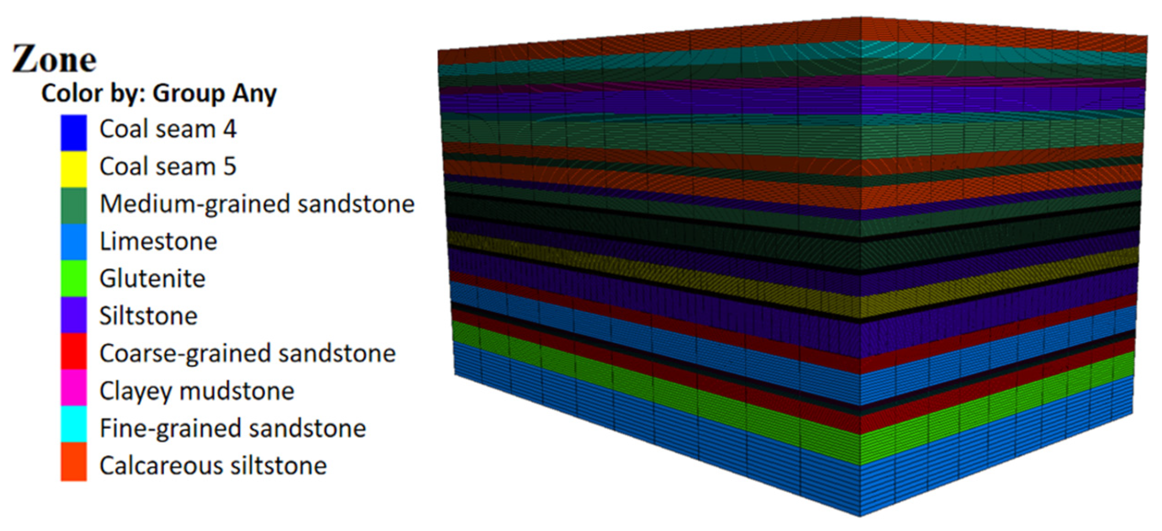
4.1. The Settings of Geology

Jinqiao coal mine is located in the south of Heyang County, Shaanxi Province, China. There are two villages and a sewage treatment plant within the mining area. Baoya Village is located in the middle of the second mining area, Zhongyuantou Village is located in the south of the second mining area, and the sewage treatment plant is located northeast of Baoya Village (Figure 4). The majority of the resource reserves in the mining area are located beneath the villages and sewage treatment plants, which significantly shortened the mine service life and reduced the resource recovery rate. According to the mine survey, the villages currently do not have the conditions for relocation. Most of the village houses are one or two floors, with flat roofs or tile roofs, and brick-concrete bearing structures, which have a certain degree of resistance to mining-induced deformation. RPB is adopted to set up protective pillars for Zhongyuantou Village, Baoya Village, and the sewage treatment plant.
Jinqiao coal mine is extracting the No. 5 coal seam that is a thick seam with an average thickness of 4.28 m. The fully mechanized longwall method is adopted, and the roof is managed by the complete caving method. The roof is a set of rock strata between the No. 5 coal seam and the No. 4 coal seam, consisting of sandy mudstone, medium-fine sandstone, sandy mudstone or mudstone, and siltstone from top to bottom. When the No. 4 coal seam is absent, the immediate roof is K4 sandstone; the immediate roof is sandy mudstone and siltstone, with unstable thickness ranging from 0 to 15.9 m, mostly 3 m to 6 m. The floor is mainly composed of mudstone and siltstone, which are fragile and have poor stability. The test results of the siltstone samples show that the compressive strength is 22.7 MPa and the tensile strength is 0.5 MPa, belonging to an unstable floor category.
Taking the geological conditions of the first mining face in the second mining area of Jinqiao coal mine as the prototype, the distribution and physical and mechanical parameters of each layer are shown in Table 1. The finite difference method is used to compare and analyze the overburden movement and surface subsidence in different RPB schemes.
The parameters listed in Table 1 are calculated based on the results of laboratory-scale samples. Special attention was paid to the correlation from the samples to the in situ rock masses. The rock mass rating system (RMR) is adopted to adjust the parameters from sample tests, and the process is illustrated in Figure 5.
The basic classification indices of the RMR include the strength of intact rock material, the RQD value, the spacing of discontinuities, the condition of discontinuities; groundwater conditions, and the orientation of discontinuities. Based on the field geological data and the test results of the physical and mechanical properties of rock cores, and after classifying them according to the RMR system, the parameters are reduced according to relevant formulas and used as the calculation parameters for this numerical analysis [8,30,31].

4.2. Model Establishment

A three-dimensional version of the finite difference method is adopted in this work. It can be used to simulate the behavioral characteristics and plastic deformation processes of three-dimensional structures of materials such as soil and rock under stress. It is capable of analyzing the disturbance effects of mining activities on the environment, predicting subsidence in coal mining areas, and assessing the stability of surrounding rock masses. Taking into account the potential impact range of the entire mining process, a three-dimensional numerical calculation model with a length of 300 m, a width of 200 m, and a height of 400 m is established. The boundary conditions and failure criteria for the coal seam in this work are determined as follows. The upper boundary of the model extends to the surface, and the lower boundary is located 30 m below the mined coal. Because of the surrounding rock movement and deformation at the lower boundary caused by mining disturbance are relatively small, it is set as a fixed boundary; the left and right boundaries fix the displacement in the x-axis direction, while the front and rear boundaries fix the displacement in the y-axis direction. The initial stress state within the rock mass depends on the weight and properties of the overlying rock strata. The Mohr–Coulomb criteria are employed.
Due to the small dip angle of the coal seam, the influence of inclination can be ignored, and the coal seam is set to be horizontal. In order to enhance computational efficiency and save storage space, the grid is divided more densely in areas close to the coal seam and more sparsely in areas closer to the ground surface. Rock strata with similar lithologies are merged, resulting in a total of 27 layers in the entire model. The model comprises 369,000 elements and 402,691 nodes. The numerical model is shown in Figure 6. The upper boundary extends to the surface, while the lower boundary is set at a depth of 30 m below the coal seam.
According to the width of the working face and the width of the reserved coal pillars, the strike length of the excavated working face is set to 160 m and the dip length to 100 m. When constructing the model, each layer is first divided into blocks, and then the unit grid is generated. The strata with similar physical properties within the calculation model are simplified into a single layer. The model undergoes self-balancing treatment before excavation [32,33].
During the simulation process, the Mohr–Coulomb Model is adopted to describe the constitutive relationship. When the load borne by the overlying rock strata in the simulation reaches its ultimate bearing capacity, the strata will undergo significant deformation [30,31]. During this process, the rock strata do not completely lose their strength characteristics; instead, they maintain a certain degree of residual strength. The existence of this residual strength is primarily attributed to the complex mechanical behavior and structural characteristics within the rock material, which enable it to retain resistance to external forces even after undergoing large deformations. This equation for the Mohr–Coulomb yield criterion is
f = σ 1 σ 3 1 + sin φ 1 + sin φ + 2 c 1 + sin φ 1 sin φ
In the equation, f is the shear stress, and σ 1 and σ 3 are the maximum and minimum principal stresses, respectively. When the shear stress f > 0, shear failure will occur.

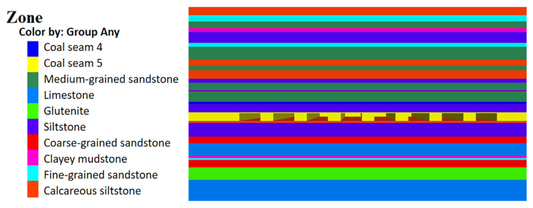
4.3. Experimental Plan

To protect the surface buildings and structures in the second mining area from mining-induced damage, RPB is employed. Therefore, it is crucial to investigate the influence of pillar width and room width on the subsidence of overlying strata. In RPB, the backfill body can further strengthen the supporting capacity of the overlying strata and reduce the surface subsidence [33]. The purpose of the simulation experiment is to study the geo-stress distribution, plastic zone distribution, and subsidence of the overlying strata after the panel is mined. And then the results were compared with them from the backfilling stage; thereby, the secondary movement and deformation behaviors of the overburden strata and surface can be captured.
Three experimental schemes are set in this work, they are denoted as 8-room-8-pillar, 8-room-6-pillar, and 6-room-6-pillar, respectively. The numbers in these designations represent the width of the room or pillar in the unit of meters.
(1)
The strata structure shaped by the 8-room-8-pillar scheme is shown in Figure 7;
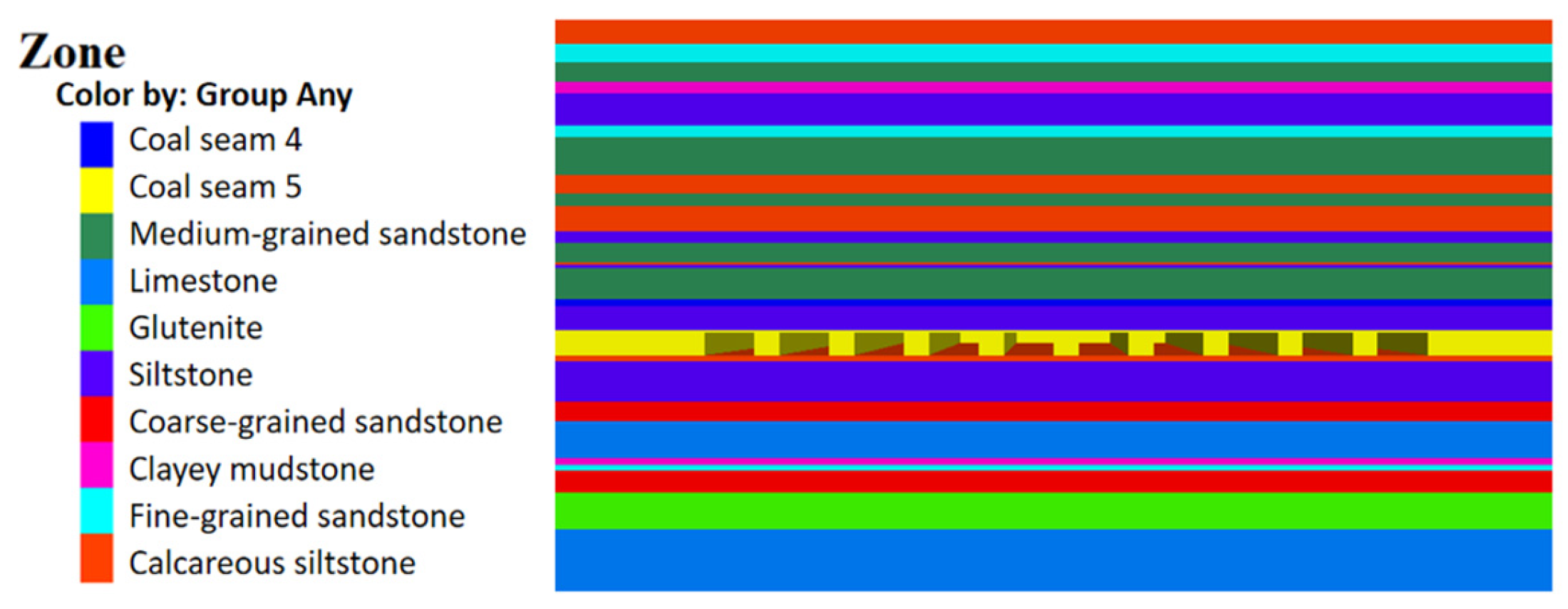
(2)
The strata structure shaped by the 8-room-6-pillar scheme is shown in Figure 8;
(3)
The strata structure shaped by the 6-room-6-pillar scheme is shown in Figure 9.
Figure 7. Model of 8-room-8-pillar scheme.
Sustainability 17 00602 g007
Figure 8. Model of 8-room-6-pillar scheme.
Sustainability 17 00602 g008
Figure 9. Model of 6-room-6-pillar scheme.
Sustainability 17 00602 g009

4.4. Analysis of Calculation Results

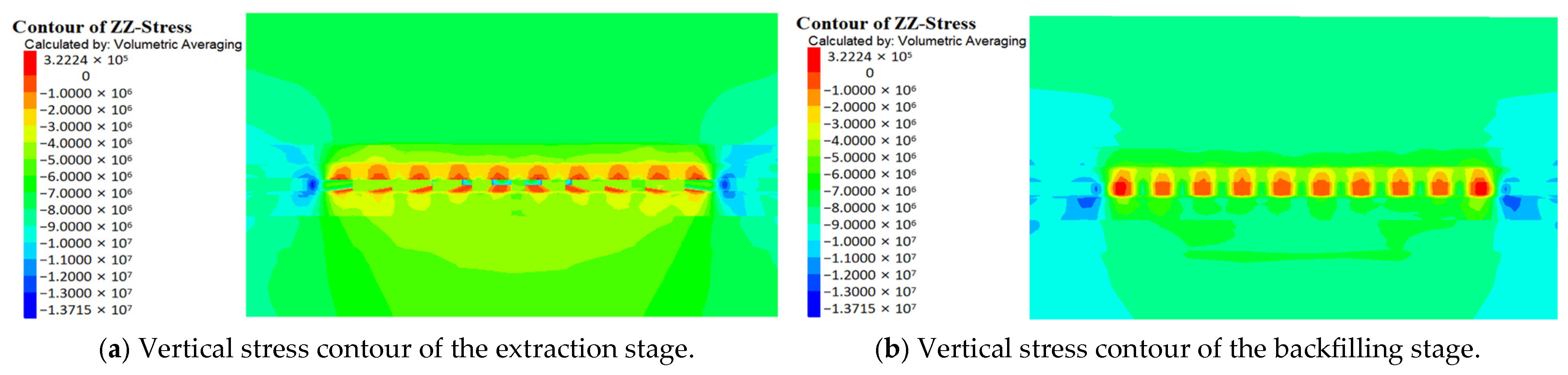
4.4.1. Stress Characteristics

During the coal mining process, certain changes occurred in the stress distribution. The stress distribution in the mining area became relatively complex, and at the same time, the stress distribution in the surrounding areas is also affected to some degree. After the coal seam is mined and a goaf area is formed, stress concentration within the surrounding rock is created as the gravity of the overlying strata above the goaf area transferred to the surrounding rock around it.
Figure 10, Figure 11 and Figure 12 present the vertical distribution for three mining schemes; the scales represent the stress values for different schemes after mining and backfilling. After mining, the original equilibrium of the surrounding rock is disrupted, causing the stress of the coal seam roof to redistribute. Stress concentration occurred in the areas adjacent to the coal pillars, and it can also be observed at the roof of rooms.
As can be seen from the above figures, with the proceeding of RPB operation, the range of mining-induced stress variations gradually increases. After mining, the original stress balance is disrupted, causing the stress in the mining area to redistribute. The basic manifestation is that the stress originally borne by the coal in the goaf area transfers to the coal pillars on both sides. The overlying rocks above the coal pillars are mainly subjected to compressive deformation, while the overlying rocks above the backfill body are mainly subjected to tensile deformation. After the coal extraction is completed, the overlying strata in the goaf area undergo bending and subsidence, with most of the stress concentration occurring at the protruding positions of the coal wall. The distribution of vertical stress is also axially symmetric with respect to the backfill body in the goaf area. After backfilling, the peak vertical stress on both sides of the coal walls in the goaf area and the range of the stress reduction zone in the overlying strata become smaller. This means that the backfill body bears the load of the overlying strata, reducing the degree of damage to the overlying rocks (Figure 13).
Figure 10a,b show that the vertical stress of the 8-room-8-pillar scheme is 1.38 MPa and 1.17 MPa, respectively, after mining and backfilling, with significant stress concentration on both sides of the backfill body edge. Figure 11a,b show that the vertical stress of the 8-room-6-pillar scheme is 1.38 MPa and 1.09 MPa, respectively, after mining and backfilling, with reduced stress concentration on both sides of the backfill body edge. Figure 12a,b show that the vertical stress of the 6-room-6-pillar scheme is 1.37 MPa and 1.11 MPa, respectively, after mining and backfilling, with a further reduction in stress concentration on both sides of the backfill body.

4.4.2. Plastic Zone Distribution

The contour plot of plastic zone that is calculated from numerical simulations can directly reflect the damage of the overlying rocks. The deformation and failure of the surrounding rock in the goaf area are essentially caused by the development of the plastic zone, which determines the failure mode and extent of the surrounding rock. The shape of the plastic zone in the surrounding rock is often irregular, generally exhibiting circular, elliptical, or butterfly shapes. “None” indicates no change in the plastic zone, “shear-n” indicates the current state of shear, “shear-p” indicates the past state of shear, “tension-n” indicates the current state of tension, and “tension-p” indicates the past state of tension. Multiple states can coexist simultaneously.
Figure 14, Figure 15 and Figure 16 show the plastic zone distribution in the roof and floor after mining and backfilling for three different schemes. Based on the distribution characteristics of the plastic zone after excavation, tensile stress appears in the roof, and scattered plastic failures occur at the edges of the support systems on both sides. After mining, the roof of the goaf area undergoes tensile failure and subsides, and the elastic–plastic zone appears at the boundaries of the remaining coal pillars. After the room extraction, plastic deformation occurred in the roof and also in the upper parts of the two sidewalls, extending towards the lower left and right corners of the goaf area. The main form of failure is shear failure; the failure mode in some areas directly above the goaf area is tensile failure. In the horizontal direction, the main failure mode is shear failure; the surrounding rock near the goaf area is in a state where shear failure and tensile failure coexist.
By comparing the plastic zone distributions of the three mining schemes. As can be seen from Figure 14, the 8-room-8-pillar scheme results in the largest plastic zone in the immediate roof, indicating poor stability of the backfill body. As can be seen from Figure 15, the 8-room-6-pillar scheme results in a relatively smaller plastic zone in the immediate roof, but this zone is still larger than that in the central area of the mining field. The edges of the overall backfill bodies in the mining field remain undamaged, ensuring the long-term stability of the backfill support structure. As can be seen from Figure 16, the 6-room-6-pillar scheme results in smaller damage to the immediate roof, which is beneficial for the long-term stability of the backfill support structure.

4.4.3. Displacement and Deformation of Roof Strata

During the mining process of coal mines, a certain degree of deformation occurs in the vertical direction. RPB can inhibit surface deformation, but different technical schemes have varying effectiveness in suppressing surface deformation. The displacements obtained from the three mining schemes are shown in Figure 17, Figure 18 and Figure 19, and the scales represent the surface subsidence values for different schemes after mining and backfilling.
As seen from Figure 17a,b, the maximum surface subsidence values for the 8-room-8-pillar scheme are 59.1 mm after the extraction and 54.9 mm after the backfilling, respectively. Figure 18a,b indicate that the maximum surface subsidence values for the 8-room-6-pillar scheme are 59.6 mm after the extraction and 54.9 mm after the backfilling, respectively. According to Figure 19a,b, the maximum surface subsidence values for the 6-room-6-pillar scheme are 59.7 mm after the extraction and 54.9 mm after the backfilling, respectively. As can be seen from the above comparison and Figure 20, as the spacing between pillars decreases, the control effect of the backfill body on the immediate roof improves. The mining scheme of 6-room-6-pillar exhibits the optimal performance in resisting roof subsidence.
In the RPB operation, the surface subsidence value increases with the increase in room width; the maximum subsidence occurring at the center of the room and the surface subsidence are symmetrical on both sides of this center. In the RPB operation, as the room width and the pillar width increase, the surface deformation values also tend to increase. The backfill body effectively controls the movement of the overlying strata, and the surface subsidence value is much smaller compared to conventional mining methods; thus, the damage to surface structures can be reduced. Therefore, under the premise of mining efficiency, it is safer to choose a smaller width of room and pillar.

5. Field Verification

As described in Section 4.1, there are two villages located in the mining area of Jinqiao coal mine. They are Baoya Village and Zhongyuantou Village. In this work, the researchers conducted a survey on the village buildings affected by the mining activities. Most of the village buildings are brick-concrete bearing structures with one or two floors (Figure 21).
In order to meet the strict requirements of local residents, the RPB method is employed in the extraction of Jinqiao coal mine to minimize ground deformation. Based on the analysis of Section 4.4, the mining scheme of 6-room-6-pillar is adopted. During the extraction of underground coal seam, the backfill body serves as the primary support in the goaf area, bearing the load of the overlying strata [34,35]. This significantly alters the original movement and deformation process of the overlying strata. The mining experience indicates that the extent of surface movement and deformation varies with the mining thickness. After the backfilling material is pumped into the goaf area, the backfill body virtually reduces not only the mining thickness but also the space for overburden movement, eventually controlling surface movement [36,37,38].
To verify the effectiveness of the mining scheme in controlling surface subsidence, measurement points were set up in two villages. Surface subsidence can be measured through several methods, such as leveling survey, GPS, and remote sensing imagery [39,40,41,42]. In this work, a leveling survey was selected as the method for measuring ground subsidence. The leveling survey observation involves measuring the settlement degree of observation points set on a building relative to fixed reference points, using a level instrument to express the settlement in numerical data. This deformation monitoring technique boasts advantages such as large coverage and insensitivity to atmospheric and seasonal influences [41,42]. The leveling survey is a widely used method for monitoring ground subsidence, which measures the ground subsidence through recording changes in the benchmark heights at different locations using a leveling instrument [42]. Taking the two villages as the survey areas, we selected stable locations in each village to establish leveling points as benchmarks, and observation points were set up on the surface of the goaf area. Altitude measurements were conducted using a leveling instrument, and initial differences between the observation points and the benchmarks were recorded. Measurements of the observation points were taken and recorded every two weeks, and the data were processed and analyzed accordingly, as shown in Table 2.
The measured elevations are calculated by adding the meter reading to the instrument height, with values ranging from 2.747 m to 2.751 m. This range reflects the minute differences in surface elevations at different measurement points and times. The settlement, which is the difference between the measured elevation and the initial elevation, reveals the vertical displacement of the surface under the influence of mining activities. As can be seen from Table 2, the settlement range is between −1 mm to −3 mm, indicating that settlement has occurred on the surface, but the settlement values are very small and within the limits specified by safety regulations. This suggests that under current mining conditions, buildings can maintain their stability and safety.

6. Discussion and Conclusions

6.1. Discussion

(1)
The study presented in this manuscript is primarily based on the geological conditions of Weibei Coalfield, and further study is needed to determine whether the laws governing the movement and deformation of the overlying strata and surface remain applicable in other regions and under special geological conditions.
(2)
The characteristics of various mining areas in China differ significantly. Due to geological structures, climatic conditions, and resource distributions, each mining area exhibits unique geological formations, coal seam distributions, and mining environments. These differences necessitate the adoption of targeted mining strategies and technological approaches based on the specific conditions of each mining area to ensure the efficiency and safety of resource extraction.

6.2. Conclusions

(1)
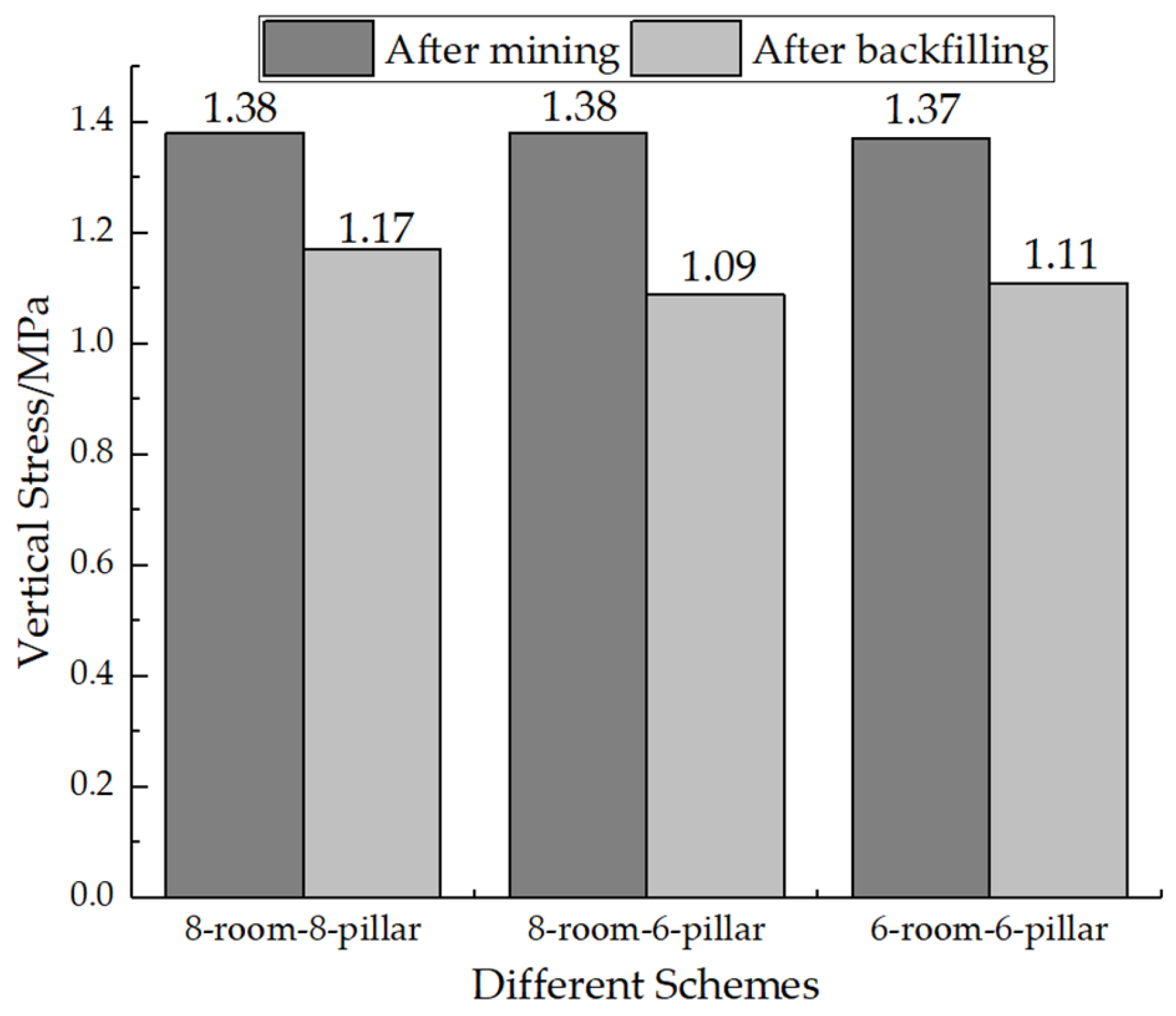
Stress transfer can be observed during the operation of RPB. The backfill body becomes a concentration area of stress, which is induced by the transmission of the weight of the overlying strata from the goaf area. The backfill body plays a stabilizing role in the movement of strata and inhibits the subsidence of the roofs. The 8-room-8-pillar scheme exhibits the highest degree of stress concentration on both sides of the backfill body, while the 6-room-6-pillar scheme has the lowest.
(2)
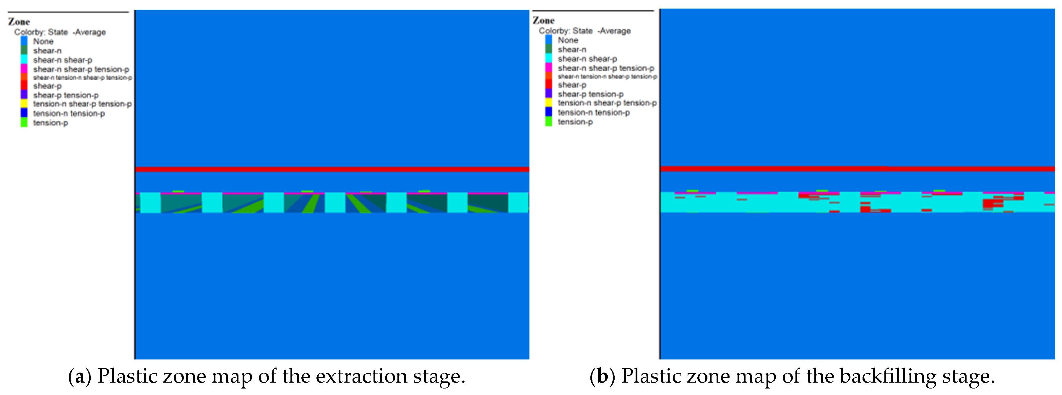
The backfilling of RPB restrains the development of plastic deformation within overlying strata. The caving and fracture zones of strata which are naturally developed in longwall mining are not present in the RPB mining. The plastic failure is confined around the upper part of the backfill body and presents a shear feature, while the immediate roof experiences less damage, primarily in the form of tensile failure. As the width of the backfill body decreases, the tensile and shear failures in the immediate roof gradually diminish, weakening the impact of overburden.
(3)
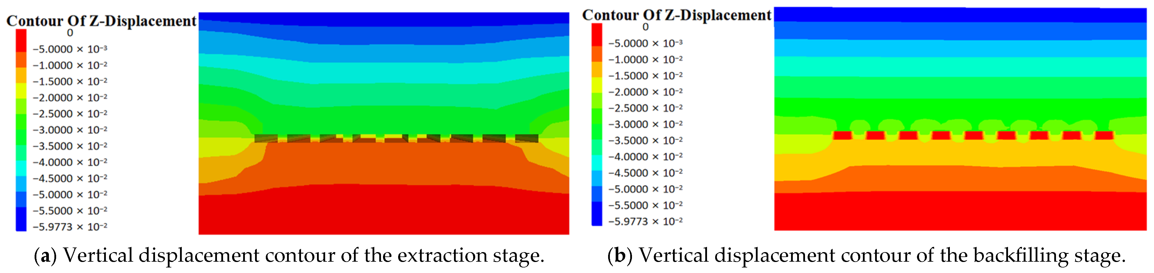
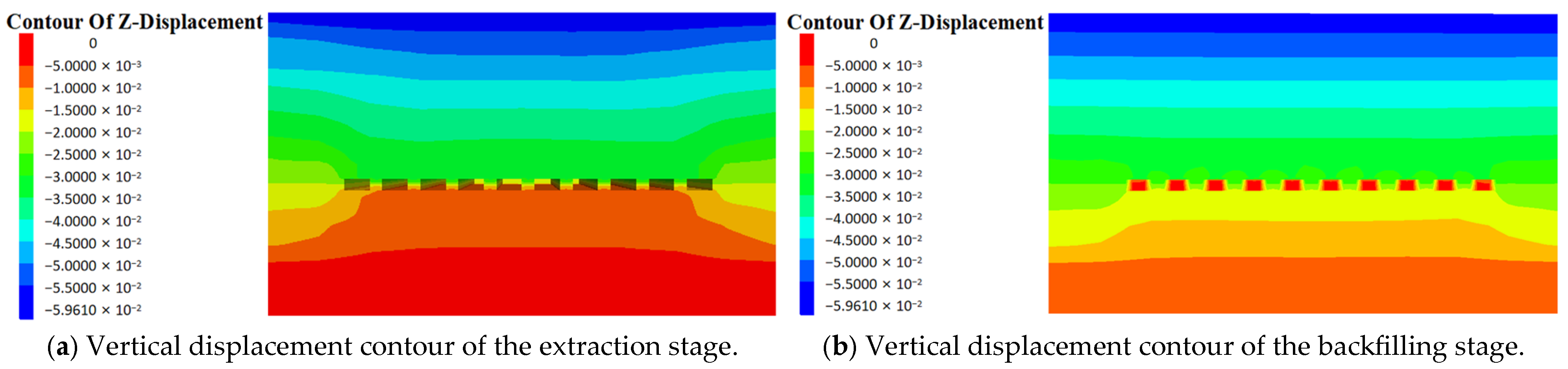
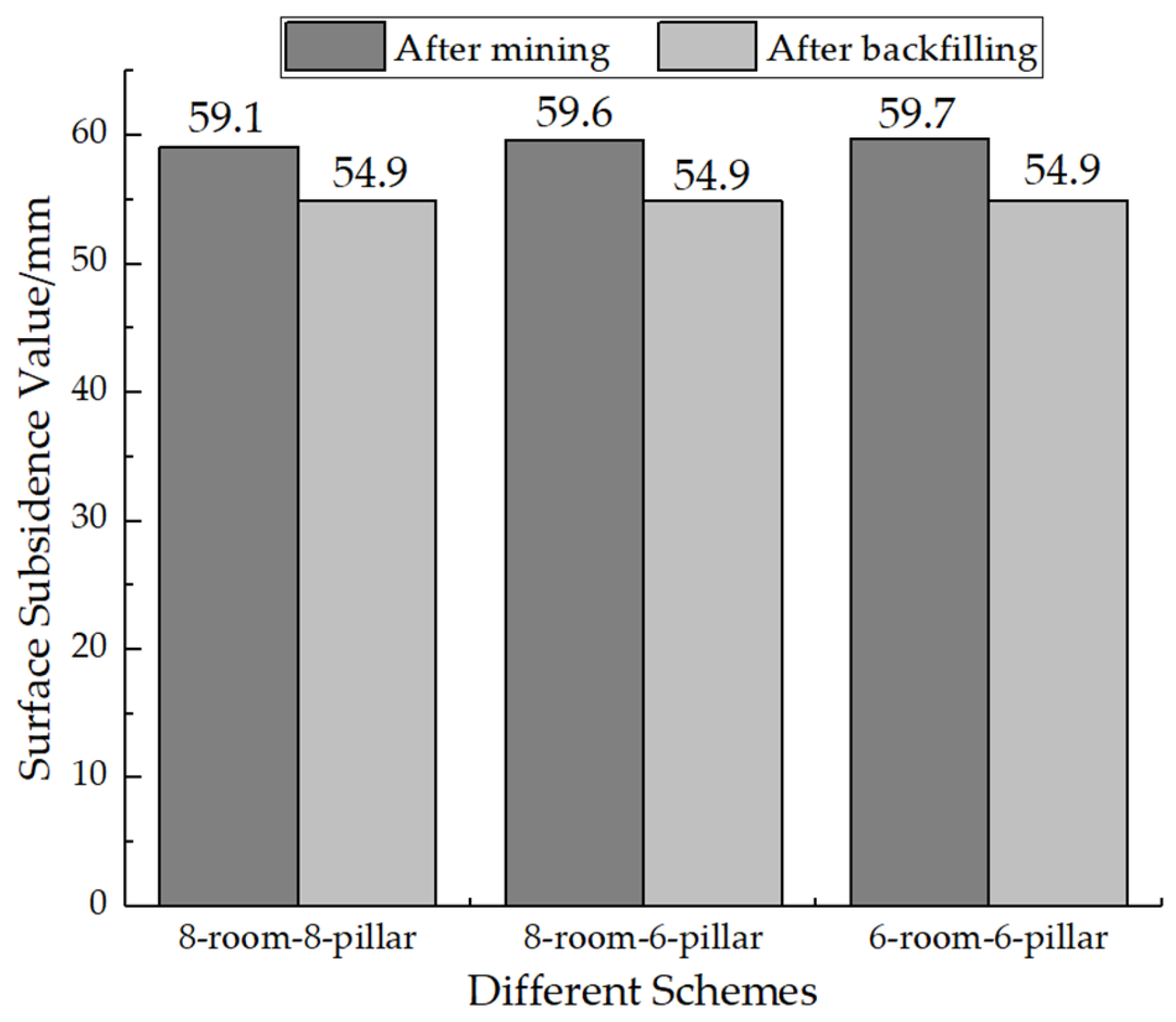
The comparisons of the three mining schemes indicate that the widths of both pillar and backfill body have an influence on the surface subsidence, but the subsidence is controlled to be within a low extent by RPB. Among the three mining schemes, the 6-room-6-pillar scheme exhibits the best inhibition effect on subsidence and can therefore protect the village buildings to a large extent.

Author Contributions

S.Y. proposed the idea. S.Y., Y.G. and R.G. conducted data collection and processing at Jinqiao Coal Mine in Heyang County, Shaanxi Province. Y.G. and R.G. performed numerical simulations. R.G. and Y.X. conducted surveys and measurements in villages surrounding Jinqiao Coal Mine in Heyang County, Shaanxi. S.Y. and Y.G. wrote and revised the manuscript. R.G. and Y.X. created the figures, S.Y. supervised the project, and S.Y. and Q.L. revised the manuscript. All authors have read and agreed to the published version of the manuscript.

Funding

This work was partially supported by the National Natural Science Foundation of China [grant numbers 52474180, 52004204]; the Postdoctoral Fellowship Program of CPSF [grant number 2022MD723829], and the Outstanding Youth Program of Xi’an University of Science and Technology [grant number 2022YQ3–08].

Institutional Review Board Statement

Not applicable.

Informed Consent Statement

Not applicable.

Data Availability Statement

Data are contained within the manuscript.

Conflicts of Interest

Author Qingzhou Liu was employed by the company Shaanxi Guojiahe Coal Industry Co., Ltd. The remaining authors declare that the research was conducted in the absence of any commercial or financial relationships that could be construed as a potential conflict of interest.

References

  1. Guo, W.B.; Hu, Y.H.; Hu, C.Q. China’s “Three-Under” Coal Mining Technology System and Engineering Practice. Coal Sci. Technol. 2024, 52, 1–21. [Google Scholar]
  2. Sarfarazi, V.; Fattahi, S.; Asgari, K.; Bahrami, R.; Wang, X. Failure Behavior of Room and Pillar with Different Room Configuration Under Uniaxial Loading Using Experimental Test and Numerical Simulation. Geotech. Geol. Eng. 2022, 40, 2881–2896. [Google Scholar] [CrossRef]
  3. Zhou, Y.J.; Li, M.; Xu, X.D.; Li, X.T.; Ma, Y.D.; Ma, Z.G. Research on Catastrophic Instability in Room and Pillar Gypsum Mining. Sustainability 2018, 10, 3773. [Google Scholar] [CrossRef]
  4. Yu, Y.; Chen, S.E.; Deng, K.Z.; Wang, P.; Fan, H.D. Subsidence Mechanism and Stability Assessment Methods for Partial Extraction Mines for Sustainable Development of Mining Cities—A Review. Sustainability 2018, 10, 113. [Google Scholar] [CrossRef]
  5. Yu, Y.; Deng, K.Z.; Chen, S.E. Mine Size Effects on Coal Pillar Stress and Their Application for Partial Extraction. Sustainability 2018, 10, 792. [Google Scholar] [CrossRef]
  6. Yu, Y.; Chen, S.E.; Deng, K.Z.; Fan, H.D. Long-Term Stability Evaluation and Pillar Design Criterion for Room-and-Pillar Mines. Energies 2017, 10, 1644. [Google Scholar] [CrossRef]
  7. Rankine, R.; Pacheco, M.; Sivakugan, N. Underground mining with backfills. Soils Rocks 2007, 30, 93–101. [Google Scholar] [CrossRef]
  8. Luo, Y. Room-and-pillar panel design method to avoid surface subsidence. Min. Eng. 2015, 67, 105–110. [Google Scholar]
  9. Feng, X.W.; Zhang, N.; Gong, L.Y.; Xue, F.; Zheng, X.G. Application of a Backfilling Method in Coal Mining to Realise an Ecologically Sensitive “Black Gold” Industry. Energies 2015, 8, 3628–3639. [Google Scholar] [CrossRef]
  10. Shao, X.P.; Li, X.; Wang, L.; Fang, Z.Y.; Zhao, B.C.; Liu, E.S.; Tao, Y.Q.; Liu, L. Study on the Pressure-Bearing Law of Backfilling Material Based on Three-Stage Strip Backfilling Mining. Energies 2020, 13, 211. [Google Scholar] [CrossRef]
  11. Zubov, V.P.; Phuc, L.Q. Development of resource-saving technology for excavation of flat-lying coal seams with tight roof rocks (on the example of the Quang Ninh coal basin mines). J. Min. Inst. 2022, 257, 795–806. [Google Scholar] [CrossRef]
  12. Zubov, V.P.; Li, Y.P. Slicing mining of thick gently dipping coal in China: Problems and improvement. Min. Inf. Anal. Bull. 2023, 7, 37–51. [Google Scholar]
  13. Chen, Y.F. Study on the Law of Strata Movement and Prediction Method of Surface Subsidence in Strip Filling Mining. Master’s Thesis, China University of Mining and Technology, Xuzhou, China, 2018. [Google Scholar]
  14. Schreiber, J.; Konicek, P.; Stonis, M. Seismological Activity During Room and Pillar Hard Coal Extraction at Great Depth. Procedia Eng. 2017, 191, 67–73. [Google Scholar] [CrossRef]
  15. Chang, Q.L.; Zhou, H.Q.; Bai, J.B.; Duan, C.R.; Li, Y.W. Stability Study and Practice of Overlying Strata with Paste Backfilling. J. Min. Saf. Eng. 2011, 28, 279–282. [Google Scholar]
  16. Ham, H.S.; Kim, Y.K.; Park, C.M.; Lee, C.H.; Kim, Y.S. A study on the effect of ground conditions of room and pillar method on pillar and room strain. J. Korean Tunn. Undergr. Space Assoc. 2021, 23, 577–587. [Google Scholar]
  17. Vlachogiannis, I.; Benardos, A. Proposed formulas for pillar stress estimation in a regular room-and-pillar pattern. Int. J. Rock Mech. Min. Sci. 2024, 180, 105826. [Google Scholar] [CrossRef]
  18. Zhu, W.B.; Xu, J.L.; Chen, L.; Li, Z.; Liu, W.T. Mechanism of disaster induced by dynamic instability of coal pillar group in room-and-pillar mining of shallow and close coal seams. J. China Coal Soc. 2019, 44, 358–366. [Google Scholar]
  19. Zhu, W.B.; Xu, J.M.; Xu, J.L.; Chen, D.Y.; Shi, J.X. Pier-column backfill mining technology for controlling surface subsidence. Int. J. Rock Mech. Min. Sci. 2017, 96, 58–65. [Google Scholar] [CrossRef]
  20. Guan, Y.W.; Wei, Y.Q.; Yang, Z.J.; Li, Z.J.; Wu, J. Failure mechanism of the key strata-pillar system in room and pillar goaf based on a numerical simulation. Chin. J. Geol. Hazard Control 2017, 28, 59–63. [Google Scholar]
  21. Waclawik, P.; Ptacek, J.; Konicek, P.; Kukutsch, R.; Nemcik, J. Stress-state monitoring of coal pillars during room and pillar extraction. J. Sustain. Min. 2016, 15, 49–56. [Google Scholar] [CrossRef]
  22. Qian, M.G.; Xu, J.L. Coal Mining and Stratum Movement. J. China Coal Soc. 2019, 44, 973–984. [Google Scholar]
  23. Zhang, Y.J.; Zhang, Z.W. Research Progress on the Failure Law and Control Technology of Overlying Rocks in Coal Mining. Coal Sci. Technol. 2020, 48, 85–97. [Google Scholar]
  24. Guo, W.B.; Bai, E.H.; Zhao, G.B. Status and Progress of Surface Failure of Overlying Rocks and Prevention and Control Technologies in High-Intensity Mining. J. China Coal Soc. 2020, 45, 509–523. [Google Scholar]
  25. Xu, J.L.; Xuan, D.Y.; Zhu, W.B. Partial Backfill Mining Technology Based on Key Stratum Control. J. Min. Strat. Control Eng. 2019, 1, 69–76. [Google Scholar]
  26. Liu, J.G.; Li, X.W.; He, T. Current Application Status and Development of Backfill Mining in China’s Coal Mines. J. China Coal Soc. 2020, 45, 141–150. [Google Scholar]
  27. Guo, Y.M.; Liu, H.F.; Yin, W. Study on the Law of Slip Failure Between Overlying Rock Strata in Coordinated Mining with Backfill and Caving. Coal Sci. Technol. 2022, 50, 92–103. [Google Scholar]
  28. Sun, X.K. Current Status and Prospects of Green Backfill Mining in Mines. Coal Sci. Technol. 2020, 48, 48–55. [Google Scholar]
  29. Yan, B.X.; Zhu, W.C.; Hou, C. Comparative Study on Theoretical Analysis and Numerical Simulation of Stress Distribution in Backfill. J. Northeast. Univ. Nat. Sci. 2019, 40, 1773–1778. [Google Scholar]
  30. Zhang, J.X.; Li, J.; An, T.L. Study on the Deformation Characteristics of Key Strata in Overlying Rocks during Gangue Backfill Fully Mechanized Mining. J. China Coal Soc. 2010, 35, 357–362. [Google Scholar]
  31. Zhang, Q.; Zhang, J.X.; Wang, J.Q. Theoretical Research and Engineering Practice on Critical Packing Ratio in Backfill Mining. J. China Coal Soc. 2017, 42, 3081–3088. [Google Scholar]
  32. Ghasemi, E.; Shahriar, K. A new coal pillars design method in order to enhance safety of the retreat mining in room and pillar mines. Saf. Sci. 2012, 50, 579–585. [Google Scholar] [CrossRef]
  33. Sahu, P.; Lokhande, D.R. An investigation of sinkhole subsidence and its preventive measures in underground coal mining. Procedia Earth Planet. Sci. 2015, 11, 63–75. [Google Scholar] [CrossRef]
  34. Jaiswal, A.; Shrivastva, B.K. Numerical simulation of coal pillar strength. Int. J. Rock Mech. Min. Sci. 2009, 46, 779–788. [Google Scholar] [CrossRef]
  35. Mathey, M. Investigation into the Mechanism of Strength and Failure in Squat Coal Pillars in South Africa. Ph.D. Thesis, University of the Witwatersrand, Johannesburg, South Africa, 2015. [Google Scholar]
  36. Zhu, W.B.; Chen, L.; Zhou, Z.L.; Shen, B.T.; Xu, Y. Failure propagation of pillars and roof in a room and pillar mine induced by longwall mining in the lower seam. Rock Mech. Rock Eng. 2019, 52, 1193–1209. [Google Scholar] [CrossRef]
  37. Ghasemi, E.; Ataei, M.; Shahriar, K. An intelligent approach to predict pillar sizing in designing room and pillar coal mines. Int. J. Rock Mech. Min. Sci. 2014, 65, 86–95. [Google Scholar] [CrossRef]
  38. Trigueros, E.; Cánovas, M.; Arzúa, J.; Baraibar, J.M. Evaluating the influence of backfilling on the stability of an abandoned room-and-pillar mine: A case study in northern Spain. Geomech. Geophys. Geo-Energy Geo-Resour. 2024, 10, 116. [Google Scholar] [CrossRef]
  39. Toderas, M. Stability Analysis of the Exploitation System with Room and Pillar by Analytical Methods. Appl. Sci. 2024, 14, 1827. [Google Scholar] [CrossRef]
  40. Yang, C.Y.; Yin, H.; Guo, S. Application of Integrated BeiDou/GNSS and Precise Leveling Method in Surface Deformation Monitoring of Old Goaf Collapse Areas. Bull. Surv. Mapp. 2024, 5, 142–146. [Google Scholar]
  41. Li, R.F.; Chang, L.; Qin, H. Comparative Study on InSAR Monitoring Technology and Leveling Measurement Technology. Eng. Qual. 2021, 39, 72–76. [Google Scholar]
  42. Liu, L. Analysis of Measurement Accuracy and Discussion on Technical Methods for Tunnel Connection in Underground Coal Mines. Inn. Mong. Coal Econ. 2024, 13, 31–33. [Google Scholar]
Figure 1. Schematic diagram of MRP.
Sustainability 17 00602 g001
Figure 2. Schematic diagram of RPB [9].
Sustainability 17 00602 g002
Figure 3. The Mechanical Model of RPB.
Sustainability 17 00602 g003
Figure 4. Satellite imagery showing the locations.
Sustainability 17 00602 g004
Figure 5. Selection of rock mechanics parameters based on engineering rock mass classification.
Sustainability 17 00602 g005
Figure 6. Three-dimensional model ready for the simulation.
Sustainability 17 00602 g006
Figure 10. The 8-room-8-pillar scheme.
Sustainability 17 00602 g010
Figure 11. The 8-room-6-pillar scheme.
Sustainability 17 00602 g011
Figure 12. The 6-room-6-pillar scheme.
Sustainability 17 00602 g012
Figure 13. Vertical stress for different schemes.
Sustainability 17 00602 g013
Figure 14. The 8-room-8-pillar scheme.
Sustainability 17 00602 g014
Figure 15. The 8-room-6-pillar scheme.
Sustainability 17 00602 g015
Figure 16. The 6-room-6-pillar scheme.
Sustainability 17 00602 g016
Figure 17. The 8-room-8-pillar scheme.
Sustainability 17 00602 g017
Figure 18. The 8-room-6-pillar scheme.
Sustainability 17 00602 g018
Figure 19. The 6-room-6-pillar scheme.
Sustainability 17 00602 g019
Figure 20. Surface subsidence values for different schemes.
Sustainability 17 00602 g020
Figure 21. Surface buildings of the villages.
Sustainability 17 00602 g021aSustainability 17 00602 g021b
Table 1. Physical-mechanical parameters of the strata.
StrataElastic
Modulus (GPa)
Shear
Modulus (GPa)
Internal Friction
Angle (°)
Cohesion (MPa)Tensile Strength (MPa)Density (kg/m3)Poisson’s
Ratio
Limestone23.502.34425.223.8022400.30
Glutenite14.307.027.8012.201.1715000.25
Coarse-grained sandstone6.572.90343.501.5025000.30
Fine-grained sandstone3.511.60350.501.0025000.40
Clay mudstone7.613.20300.200.5028000.40
Siltstone14.504.80382.251.2026000.30
Calcareous siltstone8.603.80354.502.5024000.30
No. 5 coal seam4.005.70360.0850.201330-
Medium-grained sandstone5.495.40372.501.2025000.30
Backfill body2.831.31203.800.9013700.30
Table 2. Leveling survey record.
Measurement DateMeasurement AreaMeter Reading
(m)
Instrument Height
(m)
Measured Elevation
(m)
Initial
Elevation (m)
Subsidence
(mm)
1 May 2023Zhongyuantou Village1.2501.5002.7502.752−2
15 May 20231.2481.5002.7482.750−2
1 June 20231.2491.5002.7492.750−1
1 May 2023Baoya
Village
1.2501.5002.7502.752−2
15 May 20231.2501.5002.702.752−2
1 June 20231.2471.5002.7472.750−3
Disclaimer/Publisher’s Note: The statements, opinions and data contained in all publications are solely those of the individual author(s) and contributor(s) and not of MDPI and/or the editor(s). MDPI and/or the editor(s) disclaim responsibility for any injury to people or property resulting from any ideas, methods, instructions or products referred to in the content.

