Article

Frilled Lizard Optimization Control Strategy of Dynamic Voltage Restorer-Based Power Quality Enhancement

by
C. Pearline Kamalini
* and
M. V. Suganyadevi
Department of Electrical and Electronics Engineering, Saranathan College of Engineering, Tiruchirapalli 620012, India
*
Author to whom correspondence should be addressed.
Sustainability 2025, 17(19), 8573; https://doi.org/10.3390/su17198573
Submission received: 24 June 2025 / Revised: 1 September 2025 / Accepted: 3 September 2025 / Published: 24 September 2025

Abstract

In the current energy landscape, power quality (PQ) emerges as a critical concern. Even when there is no fault on a line, PQ issues are common in all power networks since 90% of power systems’ loads are variable or inductive in nature. Variable loads cannot be avoided; hence, PQ concerns such as voltage swelling and sag will always arise. Voltage sag is one of the main issues within a distribution network, resulting in financial losses for the utility company and the customer. The Dynamic Voltage Restorer (DVR) effectively addresses voltage sags and minimizes total harmonic distortion (THD) in the distribution network. This paper proposed a novel control strategy to increase the PQ in a system. A Frilled Lizard Optimization-optimized fuzzy PI controller is proposed in this work to control the inverter. This proposed method improves the DVR’s ability to correct voltage sag and reduce total harmonic distortion as soon as possible. The PI control scheme is utilized initially to reduce the oscillations and remove the steady-state error. To increase the tendency rate of the error to zero, the PI method is applied to a fuzzy logic-based compensatory stage. The proposed approach is validated using pro-type models, as well as mathematical and Simulink modelling. In the Results Section, the performance of the proposed controllers with the DVR is tabulated and compared with other DVR controller schemes described in other research papers.

1. Introduction

PQ issues refer to an electrical system’s capacity to continuously produce an optimal power output with a noise-free sinusoidal waveform while maintaining voltage and frequency stability [1]. Variable loads and line breakdowns are the main causes of PQ issues. The network operator is accountable for voltage quality, whereas the customer is responsible for current quality [2,3]. Lightning strikes, tree branches falling on power lines, circuit breakers, and fluctuating loads are the most frequent causes of faults. These can lead to PQ issues like voltage swell, sag, and harmonics that reduce power reliability [4]. The research papers listed in the References Section have employed a range of techniques to handle PQ issues with various controllers in order to effectively manage the DVR [5].
Fuzzy logic controllers were used to fine-tune DVRs in distributed generating systems like solar farms [6]. A strong compensator DVR’s performance was examined for the distribution grid using a PI controller to fine-tune the device. Its supercapacitor storage technology enabled the DVR to swiftly compensate for voltage sags [7]. To lessen voltage sag and keep THD within allowable bounds, DVR was employed in the distribution system with a fuzzy logic controller and synchronous reference frame (SRF) [8]. The series compensating DVR device and the shunt compensating device distribution static synchronous compensator (D-STATCOM) were compared to evaluate how quickly they perform when a wind energy distribution system has a fault [9]. Using space vector pulse width modulation (SV-PWM), DVR’s VSI connection was triggered to increase operation speed [10]. Various research papers have employed the series-linked compensating DVR device to address voltage, swell, and harmonic issues that emerge in a distribution system during a fault or load variation [11]. The major objectives of this study are as follows:
  • To design a DVR to improve power quality in a grid-connected system.
  • To improve Dynamic Voltage Restorer’s (DVR) ability to minimize total harmonic distortion, this work proposes an optimized fuzzy PI controller.
  • To optimize the control parameters, Frilled Lizard Optimization is utilized.
The remaining sections of this paper are explained as follows: Section 2 provides literature survey on improving power quality. The suggested approach is discussed in Section 3. The results as well as discussion are described in Section 4. Finally, the conclusion is described in Section 5.

2. Literature Survey

Some of the existing works related to PQ enhancement in grid-connected systems with DVR are discussed in this section. Reddy et al. [12] established an improvement in PQ using an optimized cuckoo search algorithm (CSA) based on DVR. Kumar et al. [13] discussed enhancing the performance of DVR using a self-adaptive fuzzy neural network (SAFNN). The SAFNN optimizes fuzzy rules and accelerates online learning, resulting in more accurate control outputs. Gopal et al. [14] evaluated the improvement of PQ using an artificial neural network (ANN) based on DVR. The DVR was utilized to reduce the voltage sags and restore the load voltages based on its rated values.
Setty et al. [15] investigated a hybrid control approach for reducing swell and sag using a solar PV IEEE bus system. The hybrid controller reduces errors and provides a three-phase voltage to adjust for the load voltage. Singh et al. [16] discussed mitigating voltage swells and sags utilizing an optimized fuzzy-controlled DVR. The performance of the DVR was improved by controlling the quadrature and direct components using the fuzzy controller. The simulations were conducted utilizing the MATLAB (2020)/Simulink platform, and the efficacy of the results was confirmed through validation.

3. Proposed Methodology

In this work, a novel control strategy is proposed to reduce PQ problems quickly. The DVR offers an effective solution for voltage sag and helps minimize THD in the distribution network. This paper proposed an innovative fuzzy PI controller that is optimized using Frilled Lizard Optimization to improve the system’s PQ. This enhances the performance of DVR in terms of THD minimization and voltage sag correction abilities. To reduce oscillations and eliminate steady-state error, a PI control system is first implemented. To reduce the error input, the PI technique is combined with a fuzzy logic-based compensation step. The fuzzy component collects data based on errors and changes in error derivatives. In addition, a FLO algorithm optimizes the PI controller’s gain parameters. The proposed control approach is validated using a prototype model, as well as mathematical and Simulink models.

3.1. Dynamic Voltage Restorer (DVR)

The objective of the suggested DVR control technology is to offer comprehensive and efficient compensation for all PQ disturbances, such as voltage imbalance, harmonic voltage, and sag/swell, without taking into account the input capacitor size and VSI input voltage capacity [17]. Based on the instantaneous supply voltage values to the PWM inverter, which attempts to keep the load voltage at its reference value, SRF technology generates a three-phase reference voltage. A schematic representation of DVR is shown in Figure 1. The abc–dq conversion is used to change the sensed three-phase terminal voltages from the rotating reference frame to the stationary frame.
V T q V T d V T o = 2 3 cos ( θ ) cos θ 2 π 3 cos θ + 2 π 3 sin ( θ ) sin θ 2 π 3 sin θ + 2 π 3 1 2 1 2 1 2   V T a V T b V T c
where V T a , V T b   a n d   V T c denote the reference quality of load constant voltages and V T q , V T d   a n d   V T o represent quadrature component parameters. The load and terminal voltages are synchronized by a phase-locked loop (PLL).
A PI controller receives the error from the comparison of the reference and real DC bus voltage magnitudes in order to produce the voltage loss component. Equation (2) then illustrates the addition of this component to produce the reference d-axis load voltage.
V d * = V s d d c V l o s s
where V d denotes d-axis load voltage, V l o s s represents loss voltage, and V s d d c is the actual DC bus voltage. The PI controller is utilized to control the amplitude of the load voltage.
V q * = V T q d c + V q r
where V q r represents the reactive component of voltage, V T q d c denotes reference DC bus voltage, and V q * is used to produce the reference q-axis load voltage as shown in Equation (3). Equation (4) is used to find the amplitude of the load voltage at the place of common connection.
V L = 2 3     ( V L a 2 + V L b 2 + V L c 2 )
where V L denotes load voltage and V L a 2 + V L b 2 + V L c 2 indicates the summation of three-phase voltage. To supply gating pulses for the DVR switches, consequent reference frame voltages are transformed back into a–b–c frames utilizing reverse Park’s conversion, as indicated in Equation (5).
V L A * V L B * V L C * =   cos ( θ ) cos θ 2 π 3 cos θ + 2 π 3 sin ( θ ) sin θ 2 π 3 sin θ + 2 π 3 1 2 1 2 1 2   V L q * V L d * V L O *
where V L A , V L B   a n d   V L C represent the corresponding phase of the supply voltage and V L q , V L d   a n d   V L O denote the quadrature component.
The MATLAB/Simulink environment is a valuable tool for implementing the SRF method due to its extensive range of toolboxes. To synchronize the terminal voltage and load, a PLL is utilized. To assess the error among the supply voltage as well as the reference value, the three-phase terminal voltages are transformed utilizing the (abc-dq) transformation from the rotating reference frame to the stator frame

3.2. Proposed Fuzzy-Based Control Techniques

The purpose of a fuzzy logic controller (FLC) is to incorporate human experience as well as expertise into the design, as well as the presentation of control systems [18]. High performance is ensured by establishing an efficient control mechanism for DVR through the use of a PI controller and FLC together. The FLC increases multiple performance metrics and dynamic voltage (dq) responsiveness by limiting the error (sag/swell) during compensating. The main components used in building FLCs are fuzzification, rule bases or knowledge bases, defuzzification, and inference engines. In this study, two FLCs are used for the DVR mechanism: one for the d process as well as another for the q process. The PI controller receives the error value, which is calculated from the difference between the load dq voltage V D _ L O A D     o r     V Q L O A D and the reference dq voltage V D R E F     o r     V Q R E F . The proportional–integral (PI) controller can also be configured to calculate the current value of the error signal between the d- and q-axes [19]. The PI controller receives the error signal. The PI parameters are set as proportional gain K p as 40 and integral gain K i as 154.
C P I ( s ) = K p + K i s
where K p   a n d   K i are the corresponding integral as well as proportional parameters. The FLC takes the output from the PI controller to limit the additional reference dq voltage further. The error in the d or q component as well as the change in this error are expressed in the below equation:
  Ε Ι = V D R E F V D L O A D                 o r     V Q R E F V Q L O A D
Δ Ε Ι = Ε Ι Ε Ι 1
The FLC utilizes the error in the d or q component Ε as well as the change in this error Δ Ε as its fuzzy input variables, producing V D _ f l c   o r     V Q _ f l c as the fuzzy output variable. Figure 2 illustrates the operation of the FLC.
The output of PLL is combined with the actual load voltage, then it is transformed into a d q o reference frame and paralleled with the actual d q value. The generated error signal is fed as input to the fuzzy controller, which regulates the i d as well as i q components and this signal is mixed with 0   a n d   ω t . This final product obtained is d q o components and transformed back into abc components using Park’s transformation. The FLC is designed to modulate the error signal of the “d” and “q” components. The control table is illustrated in Table 1.
In Table 1, negative medium—NM, negative big—NB, negative small—NS, zero—Z, positive medium—PM, positive small—PS, positive big—PB. This method has some advantages over other previously used FLC-PI. In the proposed strategy, the integer order rate of the error at the input to ( e ) FLC is replaced by its fractional order counterpart ( μ ) . The order of the integral is replaced by a fractional order ( λ ) at the output of the FLC, representing an FO summation of the FLC outputs.
U P I F L C ( t ) = K P I d u F L C ( t ) d t
where P I denotes proportional integral and F L C represents fuzzy logic control. Tuning the fractional-order additive parameters has a greater influence on the control strategy than altering the fuzzy inference variables as well as membership functions, making this technique better for practical applications. The FLC output utilizes standard triangular membership functions and Mamdani-type inference. A novel FLO process is introduced in the next section to achieve the optimal parameters for the FLC-PI.

3.3. Frilled Lizard Optimization

The proposed solution is intended for distribution networks with grid-connected distributed generation (DG) systems. Specifically, our design and validation were carried out on a 3-phase, 415 V, 50 Hz, 20 kVA distribution feeder supplying a balanced non-linear load, with a 10 kVA DVR connected using the Matlab Simulink environment. The Frilled Lizard Optimization (FLO) scheme is one of the metaheuristic and efficient tuning algorithms that employs frilled lizards as its members [20]. In this study, a novel FLO algorithm is employed to determine the optimal parameters of PI. The initial location of the frilled lizards is established with a problem-solving space utilizing random initialization, as indicated in the equation below.
Y = Y 1 Y j Y Ν Ν × M = y 1 , 1 y 1 , e y 1 , M y j , 1 y j , e y j , M y Ν , 1 y Ν , e y Ν , M Ν × M
y j , e = L B e + γ . U B e L B e
Ε = Ε 1 Ε j Ε Ν Ν × 1 = Ε Y 1 Ε Y j Ε Y Ν Ν × 1
From the above equation, the population matrix of FLO is represented by Y , the candidate solution is denoted by Y j , the number of candidate solutions is denoted by Ν , and the number of finding best parameter and random numbers are indicated by M and γ . The upper bound and lower bond with e     t h parameter is denoted by U B e and L B e . The values of the objective function are represented by Ε and objective function with j     t h candidate solution is denoted by Ε j . In the FLO algorithm, the frilled lizard’s position is updated within the problem-solving space in two separate stages during each iteration: the exploration and exploitation phase.

3.3.1. Exploration Phase (Hunting Strategy)

The position of the candidate solution is evaluated and expressed as follows:
c p j = Y Κ :   Ε Κ < Ε j     a n d       Κ j      
From the above equation, the optimal solution is denoted by c p , the value of the objective function is represented by Ε Κ , and the population member with objective function is indicated by Y Κ .
y j , e Ρ 1 = y j , e + γ . s p j , e J . y j , e ,     j = 1 , 2 , , Ν e = 1 , 2 , , M  
Y j = Y j Ρ 1 ,     Ε j Ρ 1 < Ε j Y j ,                 e l s e
The new location of the FLO in the first phase is denoted by Y j Ρ 1 , y j , e Ρ 1 indicates its e   t h dimension, and s p j , e indicates the best gain parameter. The random number that lies among the interval 1 and 2 is indicated by J .

3.3.2. Exploitation Phase (Moving up the Tree)

The optimal location for the population individuals is computed utilizing Equation (16). If the calculated new position results in a better value for the objective function, it will replace the previous location of the respective individual in the population. This update is expressed in Equation (17).
y j , e Ρ 2 = y j , e + 1 2 γ . U B e L B e T
Y j = Y j Ρ 2 ,     Ε j Ρ 2 < Ε j Y j ,               e l s e
The new location of the FLO in the second phase is denoted by Y j Ρ 2 , y j , e Ρ 2 indicates its e   t h dimension, the maximal number of iterations is mentioned by t , the iteration counter of the algorithm is represented by T , and the value of the objective function is denoted by Ε j Ρ 2 .
The non-linear load current, power, and compensating current are calculated using Equations (8)–(13). The booster transformer injects the compensating current into the distribution line from the DVR. The DC link voltage across the storage elements was to be maintained through the design and discussion of two primary control mechanisms. The link voltage is controlled using a fuzzy and PI controller. The system is designed for a distributed generation (DG) system that is connected to a 3-phase, 415 V, 50 Hz, 20 KVA load.

4. Results and Discussion

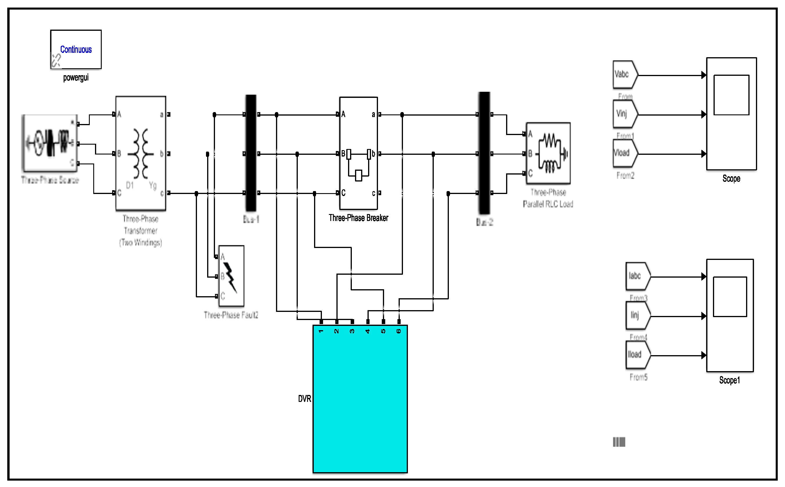
In this section, the suggested control approach is implemented and simulated utilizing MATLAB/Simulink. A 3φ, three-wire balanced grid power system supplying a balanced 3φ non-linear load is designed using MATLAB/Simulink and demonstrated in Figure 3. The faults enter the power system at a rate of 0.03 s and can last up to 0.07 s out of a total run time of 0.1 s, with a fault resistance of 0.003 inches as well as a ground resistance of 0.01 inches, correspondingly. Table 2 describes the implementation of the parameters.
Figure 4 displays three waveforms of the voltage compensation of LG fault using fuzzy DVR. The suggested approaches have the ability to identify voltage sag/swell, identify the three single-phase reference voltages of the DVR, and correct for prolonged unbalanced sag without interfering with or stopping the suggested DVR’s ability to operate as intended. It can be inferred from the load voltage found in the simulation results that compensation begins as soon as grid voltage sag or swell is identified; also, the DVR has a good response time for both voltage sag/swell identification as well as compensation operation.
Figure 5a,b display three waveforms of the voltage compensation of LLG and LLLG faults using fuzzy DVR. The fuzzy controller-based DVR has injected the compensatory voltage and alleviated the issue during the duration of the LLG failure. The fuzzy controller-based DVR injected the compensatory voltage and made it purely sinusoidal for the whole LLLG failure duration.
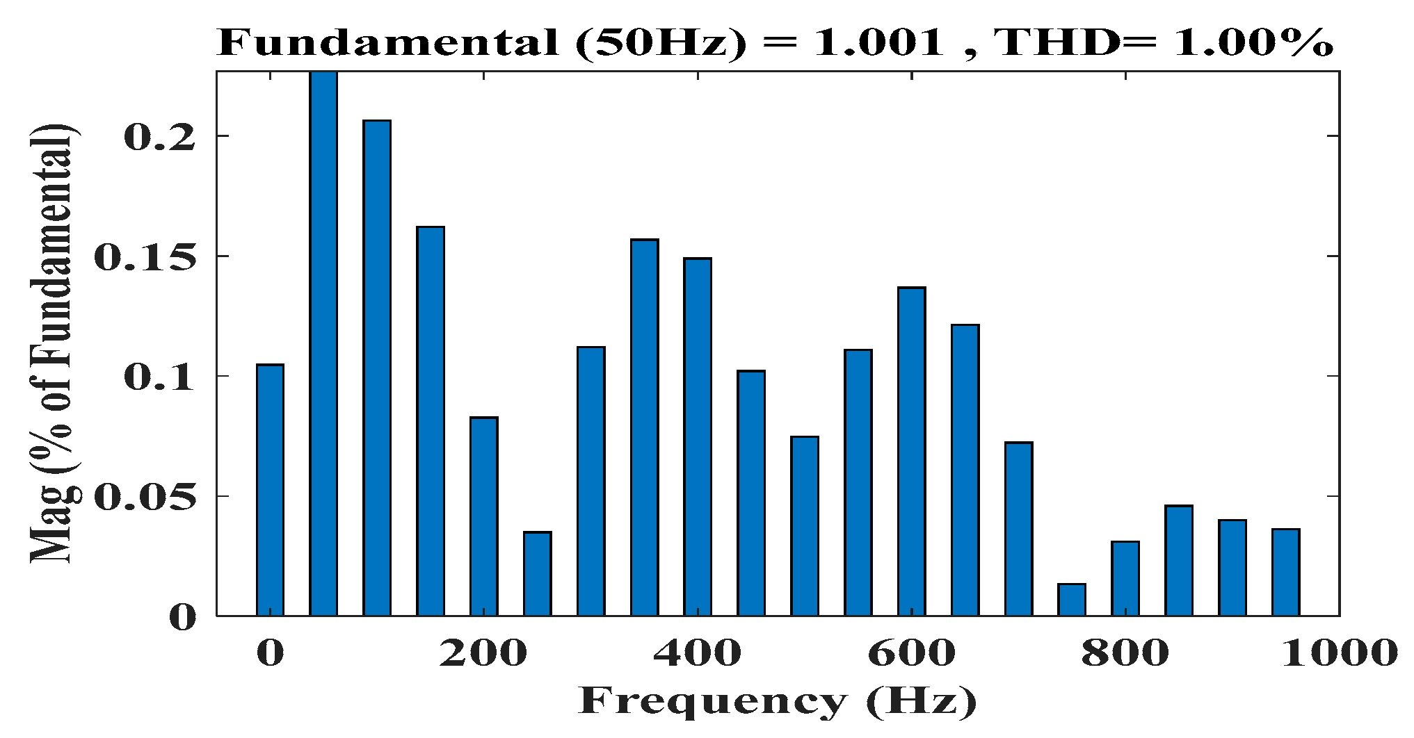
Figure 6 shows the THD of the output current for each method. The proposed method achieves a THD of 1.00%. A decreased THD reduces losses in the DVR, enhancing the system’s overall efficiency. Additionally, the suggested method operates at a lower switching frequency compared with both the conventional and other proposed methods.
Figure 7 illustrates the convergence plot of FLO with grey wolf optimization (GWO), Particle Swarm Optimization (PSO), as well as multi-strategy boosted chameleon optimization algorithm (MCSA). The objective of the optimization technique is to reduce DVR error, which is framed as a minimization problem. Using FLO, the minimum fitness is achieved by the 18th iteration. Existing optimization approaches, such as GWO, PSO, and MCSA, require more iterations, with 35, 25, and 28 iterations, respectively.
Table 3 illustrates the optimal values without DVR, with PI, and with fuzzy DVR, as well as the proposed controller parameters for the THD of the output current. Without using a DVR, harmonics are very high, in the range of 22.4%, while when using a DVR with a conventional PI controller, the THD is reduced to 1.98%. The proposed method obtained a lower THD of 1.00%, which is very small compared with other existing controllers. This smaller range of harmonics is obtained using the proposed control strategy with an optimization algorithm.

Hardware Design and Output

A strong development environment is made possible by the close integration of MATLAB and Simulink with the dSPACE software. dSPACE enables the testing of a Simulink-created simulation model on any PC. It has a plethora of features, such as high-speed real-time processors, optimal closed-loop performance, scalable systems with software-based configuration, thorough and quick software, ECU tests in a virtual environment, and much more. Multiple MATLAB Simulink models were integrated into software for experimentation and implementation.
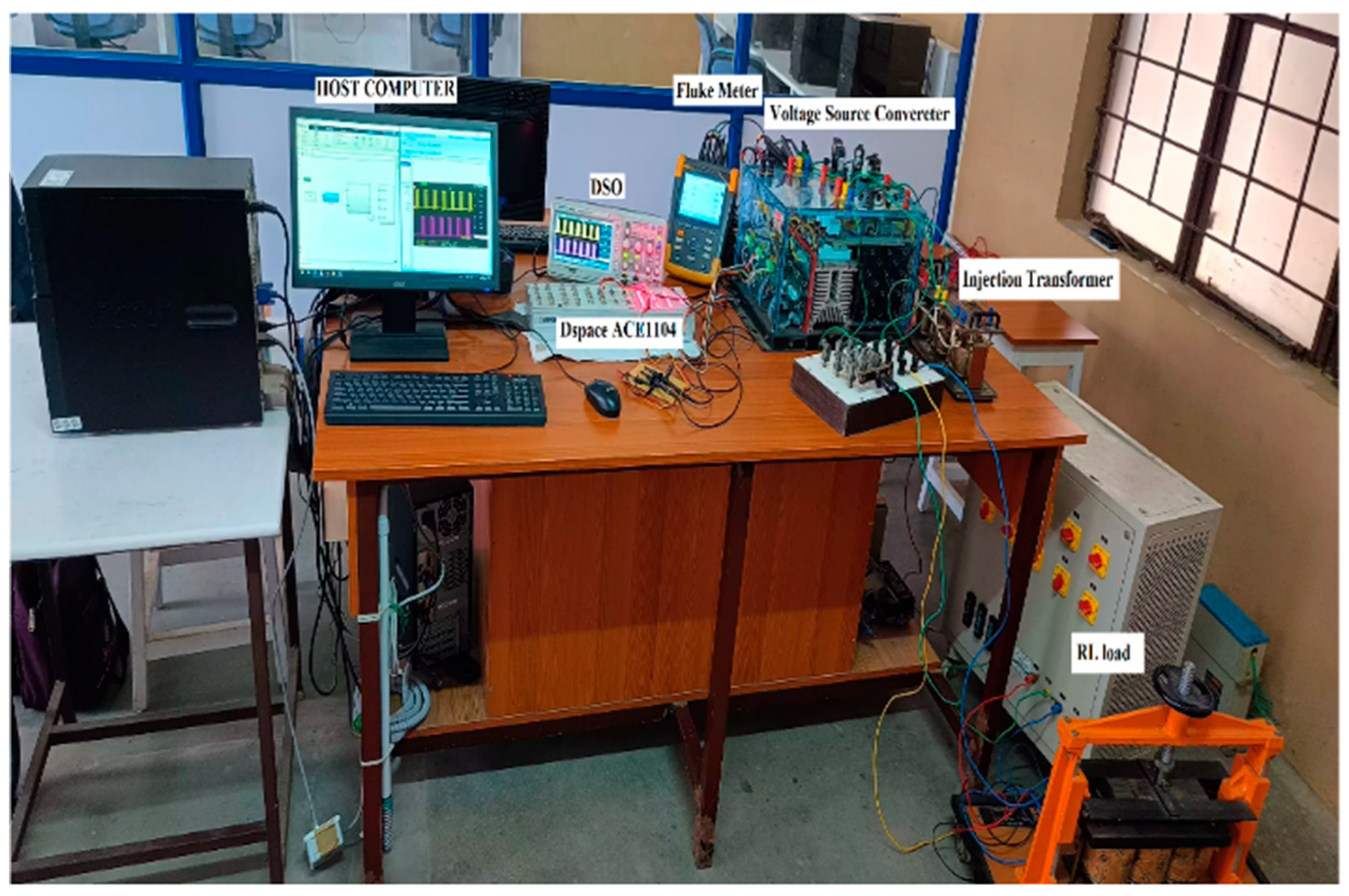
To validate the proposed frilled optimized fuzzy PI controller experimentally, the hardware prototype of the topology was constructed and is shown in Figure 8. The DVR model consists of the controller, multimeter, digital storage oscilloscope, load box, controller, and other components. The hardware setup was developed to acquire the output from DVR. The output waveform was successfully evaluated using a computer, and the simulation results encompassed both PI and fuzzy controllers. The DVR hardware, which had both fuzzy and PI controllers, efficiently handled the issue of voltage sag. The system effectively minimized the problem as long as the voltage sag persisted. In this illustration, the connection design and the outcomes are depicted post testing in a research laboratory, utilizing the requisite components.
Table 4 presents a comparison between the suggested controllers’ operation and various research articles listed in the References Section for DVR control. Compared with previous systems, the THD was significantly shorter.
Figure 9 illustrates the dSPACE pulse module output. The dSPACE graphical user interface (GUI) software was employed to control the firing angle and other parameters, as specified. Using this GUI, users could monitor real-time output and observe changes in the controller’s settings as they occurred. This figure explains the pulses provided to the converter switches.
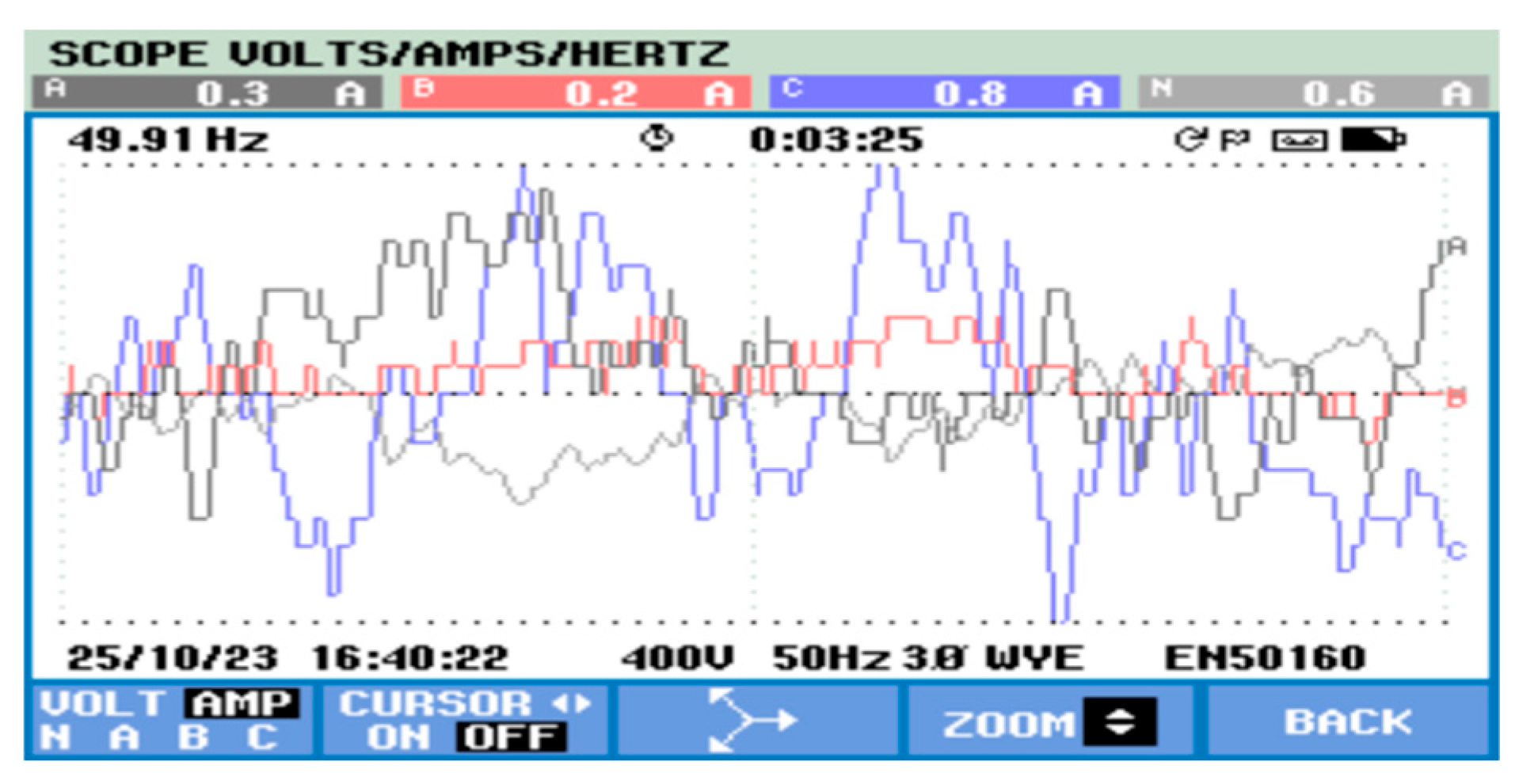
Figure 10 depicts the voltage of the power supply before a fault occurs, also known as the pre-fault source voltage. This waveform analysis demonstrates that there are no faults, indicating that the source voltage remains constant at 440 volts throughout this time period.
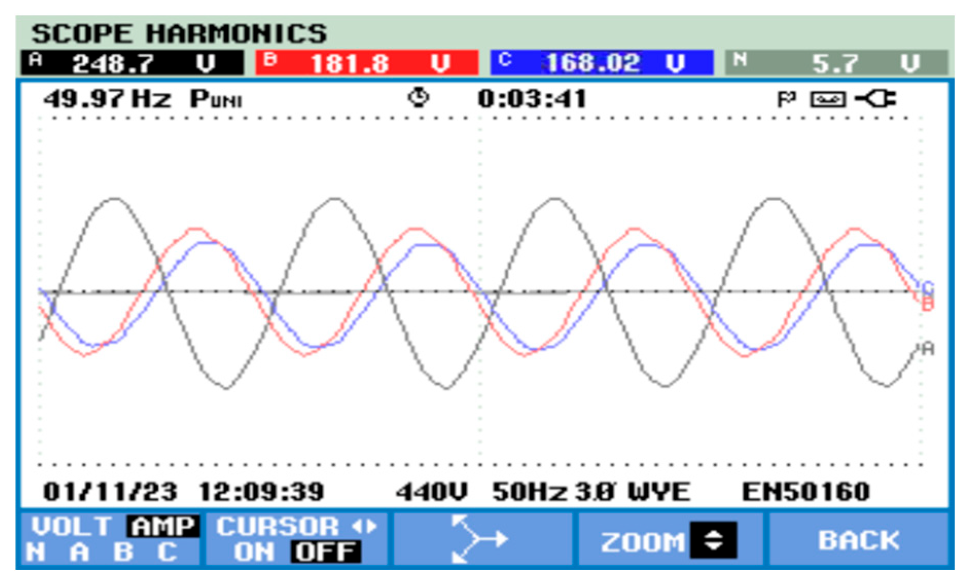
Figure 11 illustrates the voltage during the LLG fault. The LLG faults occur particularly when two conductors make contact with each other or with the ground in a power transmission. In this case, an LLG fault occurred between phases A and B within the distribution feeder. As a result of this problem, the voltage in the affected phases decreased, but the voltage in the unaffected phases remained within normal ranges.
Figure 12 shows the post-fault voltage, which represents the voltage condition of the system after the fault has occurred and during the subsequent recovery or restoration phase. After the faults have been applied to the system, the voltage reading stabilizes at 400 V.

5. Conclusions

A novel controller is proposed to address harmonic distortion and voltage sag on the distribution side using DVR. The suggested system DVR with fuzzy and PI controller reduced THD in addition to voltage sag. A variety of fault scenarios, such as LG, LLG, and LLLG, were investigated for the proposed system in order to assess and address the voltage sag problem. The system is simulated using Matlab/Simulink to reduce voltage sag under various fault scenarios, demonstrating the DVR’s ability to handle this issue. Under various failure conditions, the suggested approach smoothly adjusts the load voltage and effectively restores it to its pre-fault state. The THD of the suggested work is compared with that of existing controllers, and the results show that the suggested method obtained a lower THD of 1.00%. A hardware model was created, tested, and compared to the simulation results. In the future, the proposed work will be applied in real time with hybrid optimization methods. The main limitations are related to computational burden and hardware costs, which set practical boundaries for such modifications.

Author Contributions

Conceptualization, C.P.K. and M.V.S.; methodology, C.P.K.; software, C.P.K.; validation, M.V.S.; formal analysis, C.P.K.; investigation, C.P.K.; writing—original draft preparation, C.P.K.; writing—review and editing, M.V.S. All authors have read and agreed to the published version of the manuscript.

Funding

The research received no external funding.

Conflicts of Interest

The authors declare no conflict of interest.

References

  1. Sepasi, S.; Talichet, C.; Pramanik, A.S. Power quality in microgrids: A critical review of fundamentals, standards, and case studies. IEEE Access 2023, 11, 108493–108531. [Google Scholar] [CrossRef]
  2. Yadav, M.P.; Sujatha, P.; Kumar, P.B. Design and analysis of PV-DVR For Interconnected Wind System using Fuzzy Logic Controller. In Proceedings of the 2023 International Conference on Signal Processing, Computation, Electronics, Power and Telecommunication (IConSCEPT), Karaikal, India, 25–26 May 2023. [Google Scholar]
  3. Kumar, C.; Ghosh, P.; Chatterjee, S. Enhancement of Power Quality by mitigating of sag and swell problem in power system using DVR. IFAC-Pap. Line 2023, 55, 131–137. [Google Scholar] [CrossRef]
  4. Iqbal, A.; Ayoub, A.; Waqar, A.; Ul-Haq, A.; Zahid, M.; Haider, S. Voltage stability enhancement in grid-connected microgrid using enhanced dynamic voltage restorer (EDVR). AIMS Energy 2024, 9, 150–177. [Google Scholar] [CrossRef]
  5. Benali, A.; Khiat, M.; Denai, M. Voltage profile and power quality improvement in photovoltaic farms integrated medium voltage grid using dynamic voltage restorer. Int. J. Power Electron. Drive Syst. 2023, 11, 1481–1490. [Google Scholar] [CrossRef]
  6. Deshpande, C.; Chilipi, R.; Arya, S.R. A multi-convex composition of adaptive LMS filter-based control for dynamic voltage restorer with SSO-optimized PI gains. Electr. Eng. 2024, 107, 8243–8257. [Google Scholar] [CrossRef]
  7. Roja, S. A Fuzzy controlled grid connected Solar PV-Fed Multilevel Inverter with Series Compensator for Power Quality Improvement. J. Eng. Sci. 2024, 15, 81203–81219. [Google Scholar]
  8. Sowmyashree, N.; Kulkarni, H.; Shashikala, M.; Veeramanju, K.T. Review of Voltage Sag\Swell Mitigation Control Techniques with Dynamic Voltage Restorer in a Grid Integrated Distribution System. In Advances in Renewable Energy & Electric Vehicles. AREEV 2022; Springer: Singapore, 2024. [Google Scholar] [CrossRef]
  9. Siddique, A.; Mujahid, A.; Aslam, W.; Sajid, M.; Arfeen, Z.A. Improvements in Voltage Profile of JDW Sugar Mills’ Jawar Distribution Feeder RYK Pakistan Using ANN Based Dynamic Voltage Restorer. J. Eur. Syst. Autom. 2024, 57, 1–8. [Google Scholar] [CrossRef]
  10. Liu, A.; Wang, Y.; Zhu, Y.; Park, S.J. Research on power quality improvement system based on dynamic voltage restorer. IET Power Electron. 2024, 17, 1399–1410. [Google Scholar] [CrossRef]
  11. Anitha, P.; Kamaraja, A.S.; Karthik Kumar, K.; Bhuvanesh, A. Load voltage balancing using marine predator algorithm for power system quality improvement. J. Electr. Eng. Technol. 2024, 19, 73–82. [Google Scholar] [CrossRef]
  12. Reddy, S.G.; Ganapathy, S.; Manikandan, M. Three phase four switch inverter based DVR for power quality improvement with optimized CSA approach. IEEE Access 2022, 10, 72263–72278. [Google Scholar] [CrossRef]
  13. Kumar, P.; Arya, S.R.; Mistry, K.D. Performance enhancement of DVR using adaptive neural fuzzy and extreme learning machine-based control strategy. Int. J. Fuzzy Syst. 2022, 24, 3416–3430. [Google Scholar] [CrossRef]
  14. Gopal, B.; Murthy, P.K. Power Quality Improvement Using DVR Control DesignedWith Ann-Fuzzy In MATLAB. Webology 2020, 17, 573–592. [Google Scholar]
  15. Setty, S.N.; Shashikala, M.S.D.; Veeramanju, K.T. Hybrid control mechanism-based DVR for mitigation of voltage sag and swell in solar PV-based IEEE 33 bus system. Int. J. Power Electron. Drive Syst. 2023, 14, 209. [Google Scholar] [CrossRef]
  16. Singh, O.J.; Winston, D.P. Enhanced Method of Mitigating Voltage Sags and Swells Using Optimized Fuzzy Controlled DVR. Iran. J. Sci. Technol. Trans. Electr. Eng. 2023, 47, 147–158. [Google Scholar] [CrossRef]
  17. Abdelkader, A.B.; Mouloudi, Y.; Soumeur, M.A. Integration of renewable energy sources in the dynamic voltage restorer for improving power quality using ANFIS controller. J. King Saud Univ.-Eng. Sci. 2023, 35, 539–548. [Google Scholar] [CrossRef]
  18. Ghamari, S.M.; Narm, H.G.; Mollaee, H. Fractional-order fuzzy PID controller design on buck converter with antlion optimization algorithm. IET Control. Theory Appl. 2023, 16, 340–352. [Google Scholar] [CrossRef]
  19. Chen, Z.; Hu, X.; Wang, W.; Liu, W.; Liao, M.; Fu, Z. Power Source Converter Based on a Variable-Domain Fuzzy PI Control. Electronics 2024, 13, 674. [Google Scholar] [CrossRef]
  20. Falahah, I.A.; Al-Baik, O.; Alomari, S.; Bektemyssova, G.; Gochhait, S.; Leonova, I.; Malik, O.P.; Werner, F.; Dehghani, M. Frilled Lizard Optimization: A Novel Nature-Inspired Metaheuristic Algorithm for Solving Optimization Problems. Preprint 2024. [Google Scholar] [CrossRef]
Figure 1. Schematic diagram of DVR.
Sustainability 17 08573 g001
Figure 2. FLC operation.
Sustainability 17 08573 g002
Figure 3. Simulink DVR model.
Sustainability 17 08573 g003
Figure 4. Voltage compensation of LG fault using fuzzy DVR.
Sustainability 17 08573 g004
Figure 5. Voltage compensation of fuzzy DVR: (a) LLG fault (b) LLLG fault.
Sustainability 17 08573 g005
Figure 6. THD waveform for proposed controller.
Sustainability 17 08573 g006
Figure 7. Convergence of FLO with other conventional optimization methods.
Sustainability 17 08573 g007
Figure 8. Hardware setup.
Sustainability 17 08573 g008
Figure 9. Output of dSPACE pulse module.
Sustainability 17 08573 g009
Figure 10. Pre-fault source voltage.
Sustainability 17 08573 g010
Figure 11. Voltage during LLG fault.
Sustainability 17 08573 g011
Figure 12. Post-fault voltage.
Sustainability 17 08573 g012
Table 1. Fuzzy logic rule control table.
Ce/eNBNMZPSPSPMPB
NBNBNBNBNMNMNSZ
NMNBNBNMNMNSZPS
NSNBNMNMNSZPSPM
ZNMNMNSZPSPMPM
PSMNMSZPSPMPMPB
PMNSZPSPMPMPBPB
PBZPSPMPMPBPBPB
Table 2. Implementation parameters.
ParameterRated ValuesPer Unit Values
MAX.LOAD 50 KVA 1 P.U
DVR RATING 10 KVA 0.5 P.U
LOAD VOLTAGE 230 V 1 P.U
DVR VOLTAGE 0.115 V 0.05 P.U
DC LINK VOLTAGE 560 V -
SUPPLY FREQUENCY 50 Hz 1 P.U
SWITCHING FREQUENCY 20 KHZ 400 P.U
Table 3. Comparison of controller.
ControllerTHD%
Without DVR22.4%
With PI DVR1.98%
With Fuzzy DVR1.74%
Proposed controller1.00%
Table 4. Comparison of various controllers for DVR.
Research Article [5][6][7][8][9][10]Proposed
THD (%)7.374.282.282.582.789.51.00%
Disclaimer/Publisher’s Note: The statements, opinions and data contained in all publications are solely those of the individual author(s) and contributor(s) and not of MDPI and/or the editor(s). MDPI and/or the editor(s) disclaim responsibility for any injury to people or property resulting from any ideas, methods, instructions or products referred to in the content.