Review

Analysis of the Main Hydrogen Production Technologies

by
Juan Taumaturgo Medina Collana
1,*,
Luis Carrasco-Venegas
1,*,
Carlos Ancieta-Dextre
1,
Oscar Rodriguez-Taranco
1,
Denis Gabriel-Hurtado
1,
Jorge Montaño-Pisfil
2,
Cesar Rodriguez-Aburto
2,
Wilmer Chávez-Sánchez
2,
Cesar Santos-Mejía
2,
Pablo Morcillo-Valdivia
2 and
Nelson Herrera-Espinoza
1
1
Faculty of Chemical Engineering, Research Center for Water Treatment Processes Engineering, National University of Callao, Juan Pablo II 306 Avenue, Bellavista 07011, Peru
2
Faculty of Electrical and Electronic Engineering, Renewable Energy and Hydrogen Research Center Universidad Nacional del Callao, Callao 07011, Peru
*
Authors to whom correspondence should be addressed.
Sustainability 2025, 17(18), 8367; https://doi.org/10.3390/su17188367
Submission received: 10 July 2025 / Revised: 26 August 2025 / Accepted: 9 September 2025 / Published: 18 September 2025

Abstract

Hydrogen, as a clean energy source, has enormous potential in addressing global climate change and energy security challenges. This paper discusses different hydrogen production methodologies (steam methane reforming and water electrolysis), focusing on the electrolysis process as the most promising method for industrial-scale hydrogen generation. The review delved into three main electrolysis methods, including alkaline water electrolysis, proton exchange membrane electrolysis, and anion exchange membrane electrolysis cells. Also, the production of hydrogen as a by-product by means of membrane cells and mercury cells. The process of reforming natural gas (mainly methane) using steam is currently the predominant technique, comprising approximately 96% of the world’s hydrogen synthesis. However, it is carbon intensive and therefore not sustainable over time. Water, as a renewable resource, carbon-free and rich in hydrogen (11.11%), offers one of the best solutions to replace hydrogen production from fossil fuels by decomposing water. This article highlights the fundamental principles of electrolysis, recent membrane studies, and operating parameters for hydrogen production. The study also shows the amount of pollutant emissions (g of CO2/g of H2) associated with a hydrogen color attribute. The integration of water electrolysis with renewable energy sources constitutes an efficient and sustainable strategy in the production of green hydrogen, minimizing environmental impact and optimizing the use of clean energy resources.

1. Introduction

Energy acts as an indispensable catalyst in the advancement and evolution of humanity. In light of industrial progress, the need for conventional fossil fuels (including coal, oil, and natural gas) has increased, and total energy demand is projected to increase from 16 tera atts in 2010 to 30 terawatts in 2050. However, these energy sources are often constrained by geographic limitations and intermittent availability on a time scale. Therefore, the efficient conversion of these resources into usable energy carriers presents itself as a critical challenge to address the current energy [1]. Should briefly place the study in a broad context and highlight why it is important. According to the Intergovernmental Panel on Climate Change (IPCC, 2018), restricting global temperature rise to 1.5 °C requires urgent and extensive changes to energy infrastructures globally, underscoring the need to accelerate the adoption of clean energy [2]. Renewable energy sources such as wind, solar, and wave power, along with other natural resources, are increasingly gaining favor among scientists worldwide and are widely recognized as effective alternatives to fossil fuels [3]. However, due to the limitations inherent in its intermittent and fluctuating nature, its stability in energy supply and large-scale promotion have been limited. Hydrogen energy has enormous potential in the transition to clean energy and is an effective way to achieve large-scale decarbonization in sectors such as transportation, industry, and construction. The use of water electrolysis to produce hydrogen is not only one of the ways to obtain energy from hydrogen but also helps to solve the intermittency and variability of renewable energies [4]. Hydrogen has many attractive properties as an energy carrier and a high energy density (140 MJ/kg), which is more than twice as high as typical solid fuels (50 MJ/kg) [5]. Hydrogen has the highest specific energy of all fuels currently in use, with 33.31 kWh kg−1, in comparison, gasoline has a specific energy of 12.89 kWh kg−1 and lithium-ion batteries have a specific energy of 0.1–0.2 kWh kg−1 [6]. Hydrogen energy, with its abundant reserves, ecological and low-carbon characteristics, high energy density, diverse sources, and wide applications, is gradually becoming a key factor in global energy transformation and development [7]. The production of H2 has attracted considerable interest worldwide as a renewable and sustainable energy source for domestic, industrial, and automotive use [8] and as a raw material for fertilizer production (urea, ammonium nitrate, and ammonium sulfate) [9]. industrial production of cement, iron, steel and chemical products [10], chemical production (hydrogen peroxide and methanol), and energy generation from fuel cells. While hydrogen production from fossil feedstocks generates substantial amounts of hydrogen, it is constrained by limited resources and generates carbon dioxide emissions. Currently, most of the world’s H2 is produced using the steam fossil fuel reforming (SMR) process. Methane is a preferred option due to the high H/C ratio and its wide availability; however, it involves numerous steps and harsh operating conditions [11]. The replacement of fossil fuels with renewable fuels is one of the concerns of researchers in the modern world [12]. Currently, around 96% of global hydrogen production depends on the use of fossil fuels (naphtha reforming accounts for 30%, steam reforming of natural gas for 48%, and coal gasification for 18%), while only 4% comes from water electrolysis [13,14]. To support sustainable development, hydrogen energy has attracted significant attention due to its zero-carbon footprint and high gravimetric energy density [15]. Unlike fossil fuels, hydrogen emits only water during combustion, making it an attractive option for mitigating greenhouse gas emissions and combating climate change [16]. Currently, hydrogen production by electrolysis of water is the most important method of producing hydrogen and the main way to achieve carbon neutrality [17].
In our research, we focus on the main hydrogen production technologies, steam methane reforming and water electrolysis; we describe the different types of cells and their flow diagram of the electrolysis process. We also describe the chlorine soda technologies for obtaining hydrogen gas as a by-product of the process.
The manuscript is distinguished by offering a comprehensive, up-to-date, and technologically specific review of water electrolysis for hydrogen production as its primary focus, whereas contemporary reviews typically cover a broader range of hydrogen production techniques, including fossil fuel reforming (which is accompanied by significant CO2 emissions). Consequently, the emphasis of this article on electrolysis methods and their intricate technical details renders it considerably more specialized by comparison. Unlike broader bibliographic studies, this article explicates specific electrolysis technologies, namely alkaline water electrolysis (AWE), proton exchange membrane (PEM) electrolysis, and emerging alternatives such as anion exchange membrane (AEM) electrolysis, exploring their respective operating principles, efficiencies, cost structures, and challenges.

2. Technologies for Hydrogen Production

Hydrogen production technologies are divided into two main categories: from fossil fuels and renewable sources. From fossil fuels, hydrogen is mainly generated from steam reforming of natural gas. Renewable sources, on the other hand, use water splitting to produce hydrogen and oxygen by electrolysis, with minimal environmental impact [18]. Currently, most hydrogen production is carried out using methods based on fossil fuels. Steam methane reforming is one of the most widely used technologies in the industry for hydrogen production, due to its high efficiency and low cost. In the field of hydrogen production technology using water electrolysis, three main methodologies are used: alkaline water electrolysis (AWE), proton exchange membranes (PEM), and anion exchange membranes (AEM). Each one offers specific advantages and challenges.

2.1. Hydrogen Production Using Steam Methane Reforming (SMR)

Steam methane reforming (SMR) is the main industrial method for producing synthesis gas, which consists of a mixture of carbon monoxide (CO) and hydrogen (H2) [15]. Figure 1 shows the block diagram of the steam methane reforming (SMR) process, which is based on the principle of the catalytic reaction of natural gas (mainly methane) with water vapor under relatively high conditions (650–1000 °C) and pressures between 5 and 40 atm. It is usually carried out on a nickel-based catalyst supported on aluminum oxide (Al2O3) [19]. The thermal process of methane reforming consists of four main stages: The desulfurization unit (impurities such as sulfur compounds are removed), reforming unit, displacement reactor, and separation unit [17]. The desulfurized natural gas feed is mixed with water vapor and transferred to the steam methane reforming furnace, which is filled with a nickel-based catalyst [20]. The steam methane reforming (SMR) reaction can be represented as follows (Equation (1))
C H 4 + H 2 O 3 H 2 + C O   H 0 298 = 206   k J m o l
Raw materials in food with a higher molecular weight can also be reformed into hydrogen, as in Equation (2).
C 3 H 4 + 3 H 2 O 7 H 2 + 3 C O
Previous studies have mentioned that, given that the endothermic reaction is of great magnitude, increasing the temperature also favors the direct reaction following the principle of Le Chatelier. Methane conversion changes linearly from 83.7% at 500 °C to 87.1% at 700 °C [21]. Due to the large differences in thermodynamics and process conditions, SMR and WGS reactions are normally carried out in separate reactors using different catalysts [22]. The reformed gas (synthesis gas) passes through the CO-Shift (WGS) reactor, where carbon monoxide reacts with excess steam present in the reformed gas stream to produce additional hydrogen and carbon dioxide. The displacement reaction occurs at temperatures between 200 and 400 °C, with copper- or iron-based catalysts. The water gas displacement reaction is shown in Equation (3).
C O + H 2 O H 2 + C O 2   H 0 298 = 41   k J m o l
The hydrogen-enriched gas stream is channeled to adsorption equipment for the final refining process. During this stage, the gas mixture passes through a column of adsorbent materials under high-pressure conditions, which effectively captures contaminants such as carbon dioxide, methane, and carbon monoxide. Residual methane and other gases are often recycled back into the furnace as fuel, improving the overall efficiency of the process [23]. The resulting hydrogen is prepared for storage or distribution, depending on its application. Figure 1 shows the block diagram of the natural gas (methane) reforming process.
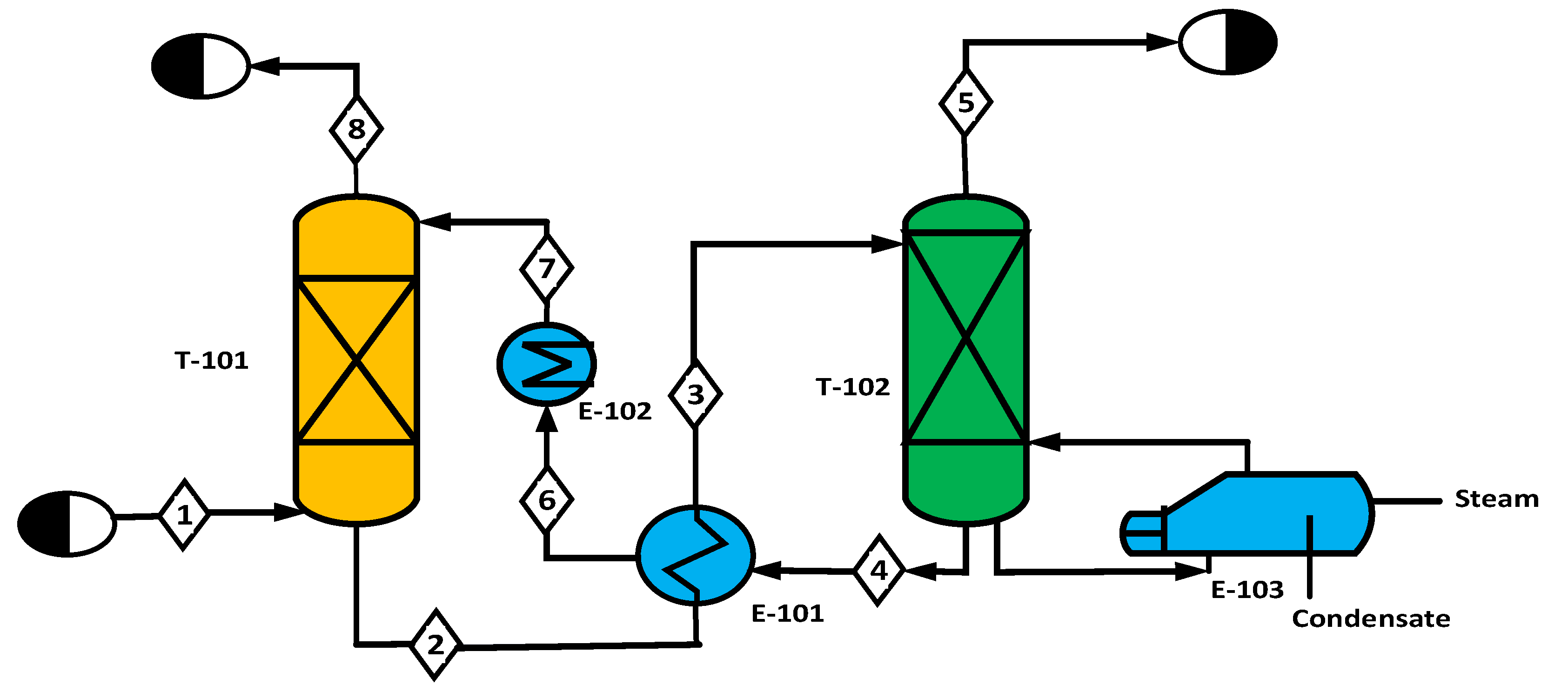
The process of separating carbon dioxide is based on the absorption of CO2 in a solvent, with the formation of reversible or irreversible intermediates, to facilitate the separation and capture of CO2 from gas streams [24]. The most commonly used solvents include monoethanolamine (MEA), diethanolamine (DEA), N-methyldiethanolamine (MDEA), and di-2-propanolamine (DIPA) [25]. Regeneration occurs through an increase in temperature; therefore, the intermediate compound decomposes into the primary solvent and the CO2 stream [26]. Figure 2 shows a process flow diagram (PFD) for carbon capture adopted from previous studies. The mixture of gases containing carbon dioxide (CO2) enters the absorption column (T-101) through stream 1, while a solvent (amine) enters through stream 7 at the top. The solvent, which now contains absorbed CO2, stream 2, is heated through the cross heat exchanger (E-101) and directed to the top of the stripper column by the current 3. Inside the column (T-102), the amine solvent is recovered, and carbon dioxide (CO2) is released with the heat supplied by the reboiler using steam (E-103). After condensation, the CO2 gas produced exits through the top of the separator stream 5. The amine solvent from the separator is cooled (E-102) and recycled back to the absorber stream 7. The captured CO2 is compressed and then transported for various uses or injected into deep underground rock formations for permanent storage.

2.2. Hydrogen Production by Electrolysis of Water

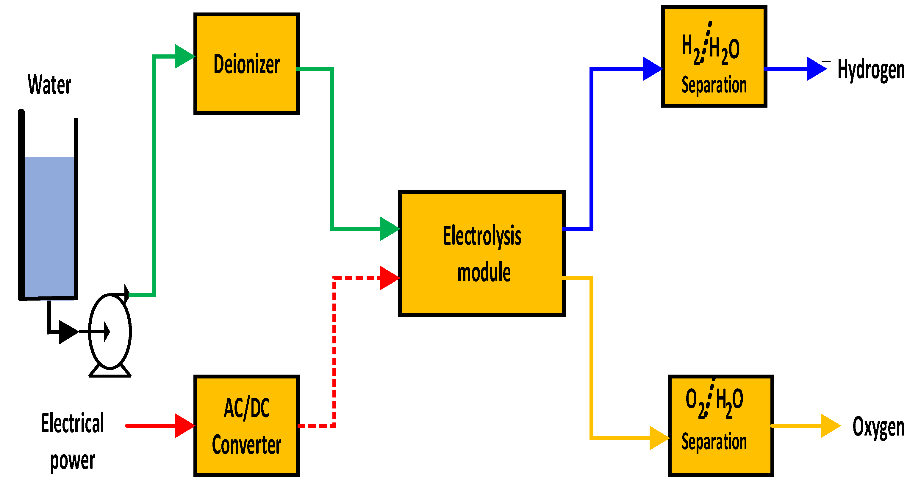
Water electrolysis is the process of breaking down water (H2O) into its constituent elements, hydrogen (H2) and oxygen (O2), using an electric current. This operation is carried out using an electrolyzer, a device containing two electrodes and an electrolyte. Figure 3 shows a schematic representation of the technology used to generate hydrogen and oxygen through an electrolysis module. Water or an alkaline solution is introduced into the electrolytic cell, where direct current electrical energy derived from an alternating current converter is transmitted through the electrodes to the electrolysis cell. The two-phase mixtures composed of water and gas (hydrogen and oxygen) are released from the electrolysis cell and directed to the gas separators in order to obtain pure hydrogen and oxygen. The three main technologies used for water electrolysis are alkaline electrolysis, proton exchange membrane (PEM) electrolysis, and anion exchange membrane electrolysis. Each method has its own characteristics and operating conditions. However, the main chemical reaction is the same for each type of electrolyzer. Alkaline electrolyzers represent state-of-the-art technology, and proton exchange membrane (PEM) technologies are in the demonstration phase, while solid oxide electrolyzers are still in the R&D phase [27].

2.2.1. Alkaline Water Electrolysis (AWE)

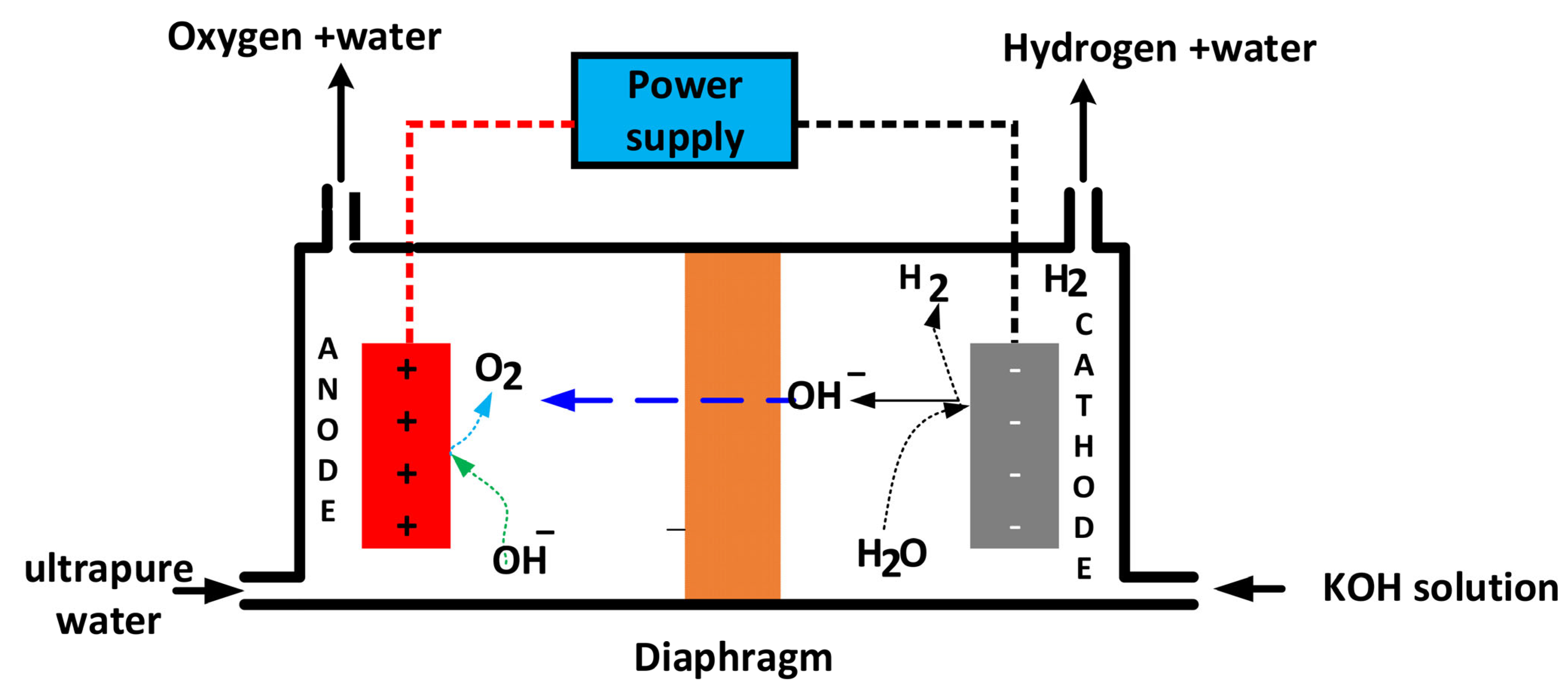
Alkaline water electrolysis (AWE) represents an advanced and well-established methodology for generating hydrogen gas through the dissociation of water molecules by applying direct electric current [5]. It operates in an alkaline environment, typically using an aqueous solution of potassium hydroxide (KOH) or sodium hydroxide (NaOH), which acts as a conductive medium to facilitate the flow of ions between the electrodes [28]. The concentration of potassium hydroxide (KOH) solution is traditionally 20 to 30% (w/w) [29]. According to basic electrochemistry, the AWE cell charged with an aqueous electrolyte solution generates hydrogen gas at the cathode and oxygen gas at the anode. The structure of AWE electrolysis consists of two electrodes: the anode is made of a corrosion-resistant material, such as nickel; the cathode can also be made of nickel or stainless steel, and a porous permeable diaphragm immersed in the electrolyte separates the cathodic and anodic compartments. As a direct electric current passes through the cell, the process of water splitting occurs [30]. The system involves two half-cell reactions in the cathode and anode compartments, known as the hydrogen evolution reaction and the oxygen evolution reaction. On the cathode side, water molecules gain electrons and undergo a hydrogen evolution reduction reaction, producing hydrogen gas and OH ions.
The half-reaction occurring at the cathode is represented by Equation (4)
4 H 2 O + 4 e 2 H 2 + 4 O H  
OH ions pass through the diaphragm due to the difference in concentration between the cathode and anode sides, as well as the effect of the electric field.
The ions (OH) are transformed by oxidation into oxygen (O2) and water molecules, as represented by Equation (5).
4 O H   2 H 2 O + O 2 + 4 e  
The overall chemical reaction in the alkaline water electrolysis cell is shown in Equation (6), where 2 moles of water produce 2 moles of hydrogen gas at the cathode and 1 mole of oxygen gas at the anode (Equation (6))
2 H 2 O 2 H 2 + O 2  
Alkaline electrolysis operates at lower temperatures, such as 30–80 °C, with an aqueous solution (KOH/NaOH) as the electrolyte [31]. The water used to prepare the potassium hydroxide solution has a conductivity of 1–2 μS/cm, making it suitable for alkaline water electrolysis (AWE) [32]. Figure 4 illustrates an alkaline electrolysis cell in its basic form, comprising two electrodes, a diaphragm, an electrical power source, and the inlet for water and electrolyte (potassium hydroxide solution), along with the outlets for hydrogen and oxygen gases.
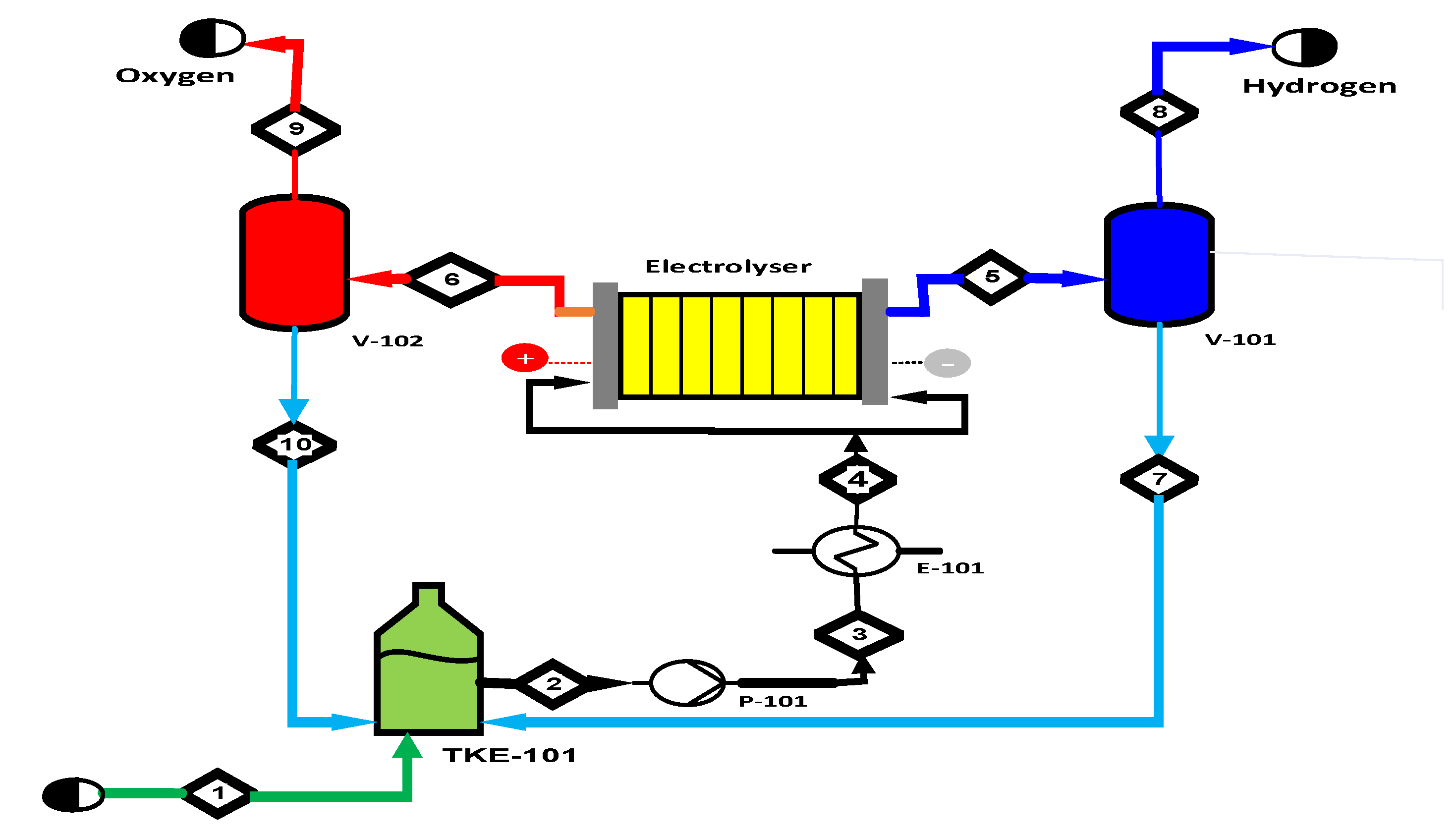
Figure 5 shows a simplified process flow diagram (PDF) for hydrogen production through alkaline water electrolysis. The diagram consists mainly of an electrolyzer, two gas-liquid separators (V-101 and V-102) for hydrogen and oxygen, a pump (P-101), a heat exchanger (E-101), and a water tank (TKE-101). Sodium hydroxide electrolyte solution is fed by stream 1 into the vessel (TKE-101); a pump (P-101) raises the electrolyte pressure; the pump outlet, stream 3, is heated by an exchanger (E-101); then stream 4 is sent to the electrolysis cell, where hydrogen gas is produced at the cathode and oxygen at the anode. The general chemical equation for water dissociation is (Equation (7))
2 H 2 O ( l ) 2 H 2 ( g ) + O 2 ( g )   H 0 = 285.8   k J m o l 1  
A mixture of electrolyte and hydrogen gas leaving the electrolytic cell via stream 5 is introduced into the gas-liquid phase separator (V-101), where the two phases are separated. The gas phase leaves the system, and the liquid phase is discharged to the (TKE-101) to be recirculated to the electrolysis cell. The oxygen/electrolyte gas mixture flows out of the cell through stream 6 and enters the phase separator, where the oxygen exits the system and the liquid phase from stream 10 returns to the tank (TKE-101).

2.2.2. Proton Exchange Membrane Electrolysis (PEMWE)

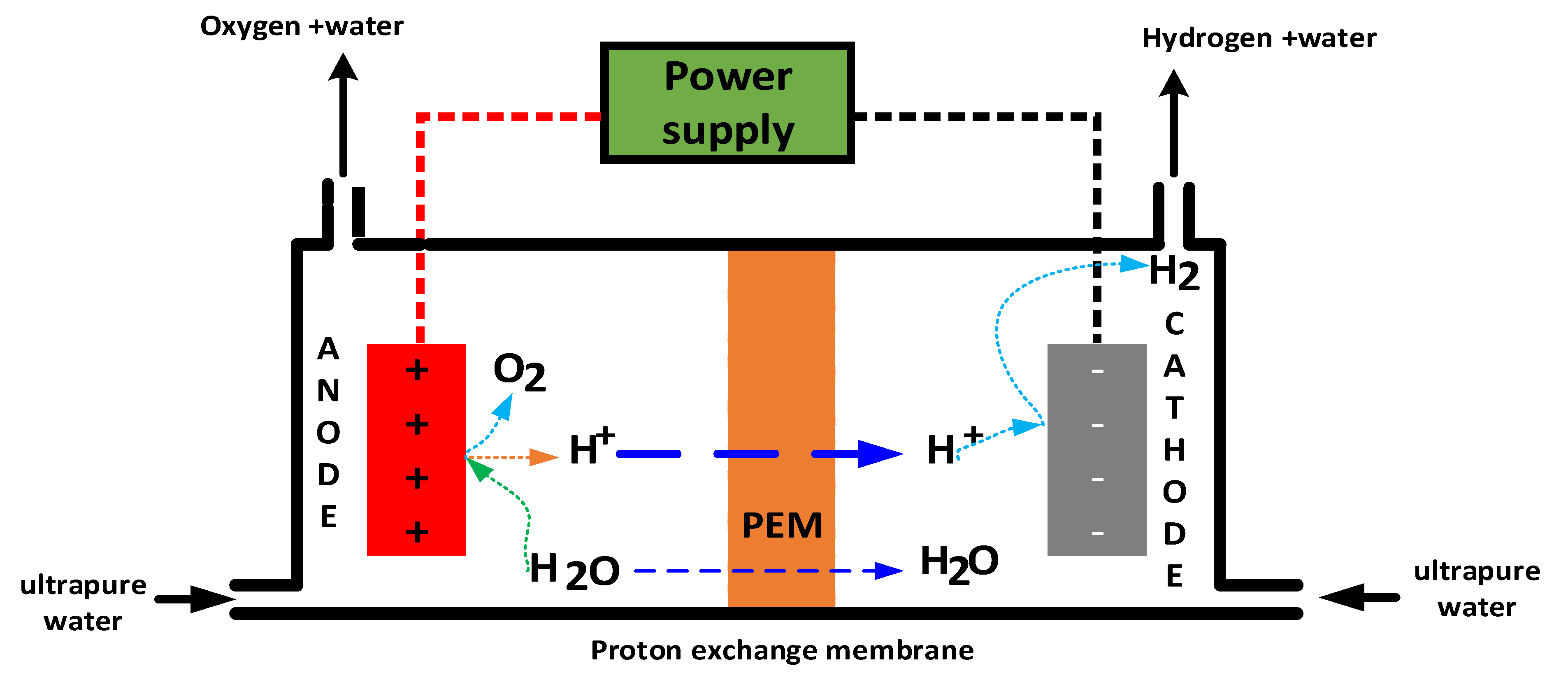
Proton exchange membrane water electrolyzers (PEMWE) are expected to contribute significantly to the green hydrogen market. However, the market penetration of PEMWE is negligible, accounting for less than one gigawatt of global capacity [33]. Proton exchange membrane (PEMWE) electrolysis, as one of the most mature methods for green hydrogen production, has expanded rapidly, and global installed electrolyzer capacity is expected to reach 170–365 GW by 2030 [34]. In order to achieve zero emissions by 2050, proton exchange membrane water electrolyzer (PEMWE) capacity should reach 1130 GW by 2050 [35]. PEM electrolysis stands out for its high efficiency and adaptability to renewable energy sources such as wind and solar power [36]. Proton exchange membrane electrolysis (PEM electrolysis) uses ultrapure water as an electrolyte, electrically separating the anode and cathode by means of a proton exchange membrane. The solid polymer membrane plays a crucial role by allowing protons (H+ ions) to pass through while preventing the mixing of hydrogen and oxygen [37]. In electrolysis, water is electrochemically split into hydrogen and oxygen at their respective electrodes, hydrogen at the cathode and oxygen at the anode. A PEM cell consists of a proton exchange membrane sandwiched between two layers of catalyst that serve as the system’s electrodes, which typically consist of an iridium-based catalyst for the anode and a platinum-based catalyst for the cathode. Currently, ruthenium (Ru)-based and iridium (Ir)-based materials stand out as the most effective anode catalysts in terms of equilibrium activity and stability [38]. When voltage is applied to both electrodes, water oxidizes at the anode, forming oxygen (O2) and protons (H+) according to Equation (8).
2 H 2 O O 2 + 4 H + + 4 e  
These protons migrate through the membrane to the cathode side (completing the electrochemical circuit). Electrons leave the anode through the external power circuit, which provides the driving force for the reaction. On the cathode side, protons and electrons recombine to produce hydrogen, according to Equation (9).
  4   H + + 4 e 2 H 2  
The overall chemical reaction in the AWE cell is shown in Equation (3), where 2 moles of water produce 2 moles of hydrogen gas at the cathode and 1 mole of oxygen gas at the anode (Equation (10))
2 H 2 O 2 H 2 + O 2  
The latest generation of electrocatalysts for PEM electrolysis are highly active noble metals such as Pt/Pd for the hydrogen evolution reaction (HER) at the cathode and IrO2/RuO2 for the oxygen evolution reaction (OER) at the anode [17]. The quality of water entering the cell must have a conductivity of approximately 0.05–0.08 μS/cm for proton exchange membrane (PEM) electrolysis [32]. Previous studies have mentioned that PEM electrolysis prefers Type I deionized water (conductivity < 0.056 μS/cm) [39]. Most studies assumed reverse osmosis (RO) integrated with ion exchange (IX) as the method of water purification to achieve conductivities lower than 1 μS/cm. The integration of reverse osmosis and electrodeionization (EDI) systems allows ultra-pure water with conductivities lower than 0.01 μS/cm to be obtained. PEM electrolyzers have a good level of technological readiness (TRL) of approximately 8–9. They operate at low temperatures (30–100 °C) and high pressures (10–200 bar).
Despite its advantages, it also faces several key challenges, such as dependence on novel and expensive metal catalysts, such as platinum and iridium. In addition, the acidic operating environment limits the range of compatible materials and accelerates membrane degradation [40]. According to the most recent literature available, the consumption (load) of platinum group metals (PGMs), such as platinum (Pt) and iridium (Ir), in proton exchange membrane (PEM) water electrolysis technology is generally reported as milligrams per square centimeter (mg/cm2) for the electrode area. PEM electrolysis typically uses 0.4 mg/cm2 of Pt and 2.5 mg/cm2 of IrO2, which translates to iridium consumption of between 0.67 and 1 g/kW for state-of-the-art stacks [41]. Previous research has indicated that proton exchange membrane electrolysis of water (PEMWE) technology has predicted that the platinum group metal content in the years 2022 and 2026 and the final target is 3, 0.5, and 0.125 mg/cm2, along with 0.8, 0.1 and 0.03 g/Kw [42]. Perfluorinated membrane materials (such as Nafion), noble metal catalysts (Pt and Ir), and precious metal coatings are the largest contributors to the cost of PEM electrolyzer membranes and cells [33]. The cost reduction initiatives focus on decreasing the loadings of noble metals, developing more economical membrane alternatives, and replacing titanium with more cost-effective materials or coatings [43]. Proton exchange membranes (PEM) chemically degrade due to the formation of peroxide at the electrodes, particularly the cathode, and this degradation significantly reduces the efficiency of the cell. Hydrogen peroxide and other reactive oxygen species (ROS) attack and break down the polymer chains within the membrane, causing structural weakening, thinning, and eventual failure, thereby diminishing the membrane’s ability to conduct protons and separate gases [44]. “Doping a catalytic layer with materials such as cerium oxide (CeO2) can enhance the durability of the catalyst and extend the lifespan of the fuel cell by mitigating membrane degradation [42]. Hydrogen purity requirements vary by application, but common methods like PEM electrolysis and metal membrane purification can achieve high purity levels (99.999% or more), while standard alkaline electrolysis may produce 99.5–99.9% purity, requiring further purification for sensitive uses like fuel cells or electronics [45]. Hydrogen purity impacts fuel cell life and, by extension, the overall life cycle cost of hydrogen systems, as lower purity can lead to catalyst degradation, reduced efficiency, and increased replacement frequency [46]. Fuel cells, especially Proton Exchange Membrane Fuel Cells (PEMFCs), require very high purity hydrogen to operate efficiently. Impurities such as moisture, oxygen, nitrogen, carbon monoxide, carbon dioxide, hydrogen sulfide, and ammonia can degrade fuel cell performance [47].
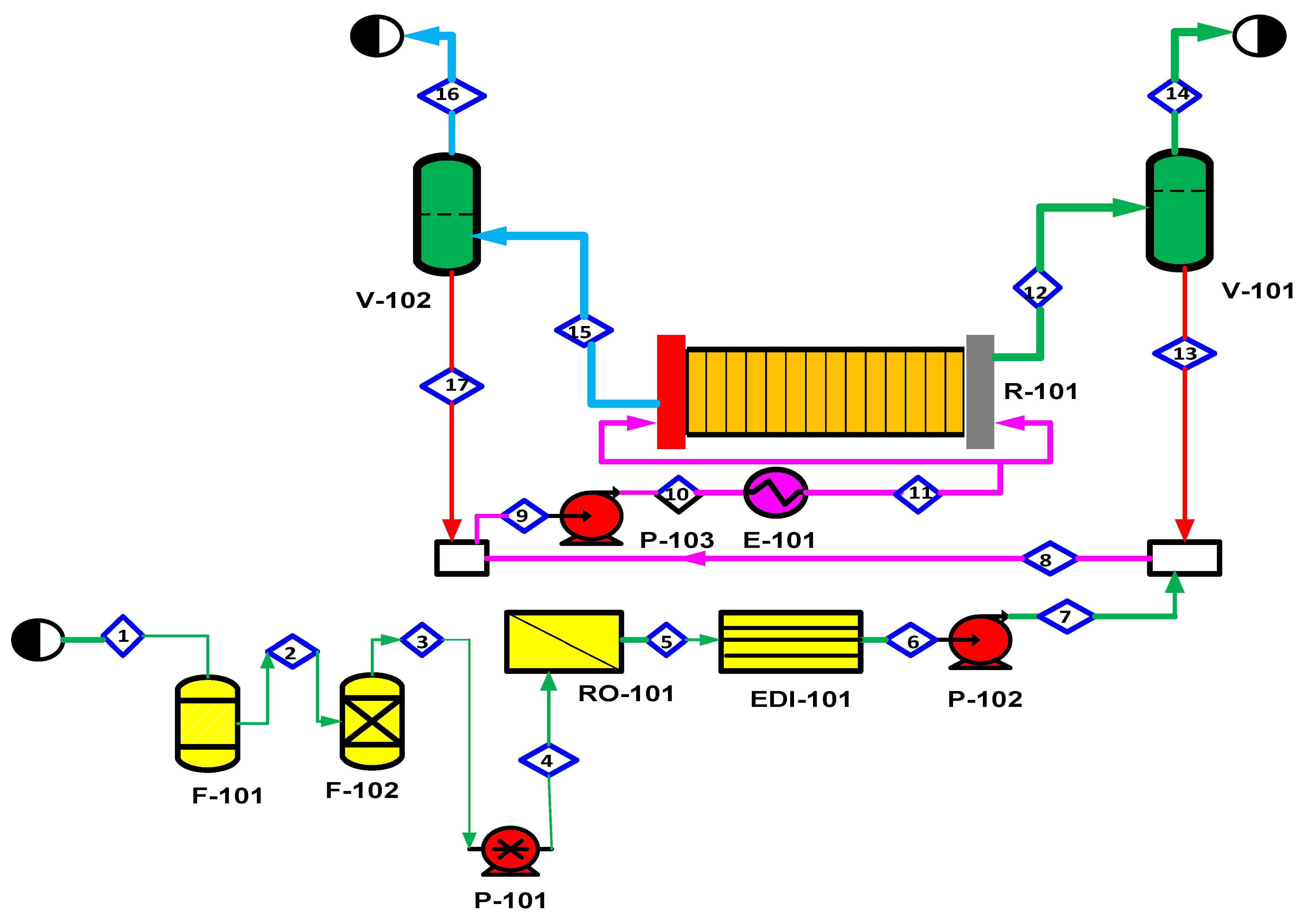
Figure 6 shows a simplified process flow diagram (PDF) for hydrogen production through water electrolysis using proton exchange membranes (PEMWE). The diagram consists mainly of an electrolyzer, two gas-liquid separators (V-201 and V-202) for hydrogen and oxygen, three pumps (P-201), a heat exchanger (E-201), a reverse osmosis module, and a water tank (TKE-201). Tap water is introduced into stream 1, passing through an activated carbon filter that removes residual chlorine. Stream 2 is then introduced into a softener with ion exchange resins to remove calcium and magnesium ions. Stream 3 is then introduced into a pump (P-101) that increases the pressure before passing to the reverse osmosis unit. Stream 5 then enters the electro-ionization equipment, where trace ions (calcium, magnesium, chloride, sodium, etc.) are removed. Stream 7, together with stream 13, output from the phase separator (V-101), and stream 17, from the separation (V-102) of gas (oxygen) and liquid (water), are mixed. The mixture enters the pump (P-103) in order to increase the pressure of the liquid. Stream 10 enters a heat exchanger in order to bring it to the appropriate temperature (60–80 °C). Stream 11 is sent to the electrolysis cell, where hydrogen is produced at the cathode (stream 12) and oxygen at the anode (stream 15). Hydrogen production (Figure 7) may require additional unit operations, depending on the quality of hydrogen required, such as drying, cooling, and purification of hydrogen.

2.2.3. Anion Exchange Membrane Electrolysis (AEMWE)

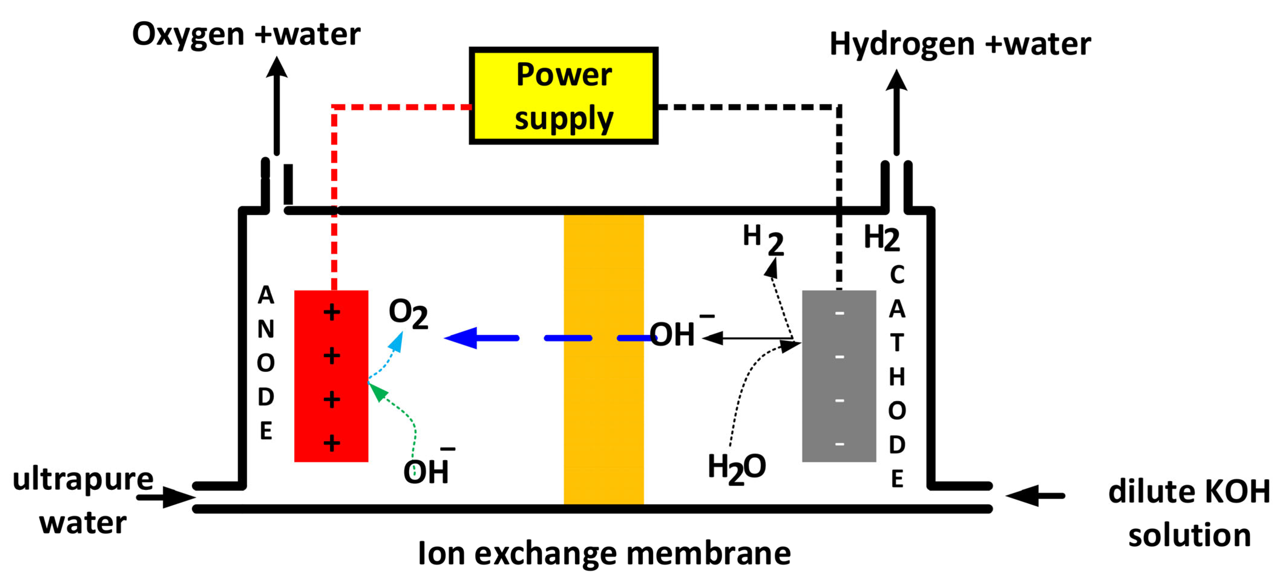
Anion exchange membrane (AEM) electrolysis uses a semipermeable membrane that conducts negatively charged ions (anions) to break down water molecules and obtain hydrogen (H2) and oxygen (O2) gases [48]. In an AEM electrolyzer, the anode and cathode are separated by an anion exchange membrane that allows negatively charged hydroxide ions (OH) to pass through while blocking other ions and gases [49]. During electrolysis, water is fed into the anode chamber, where it oxidizes to produce oxygen gas and hydroxide ions. The hydroxide ions are transported through the AEM to the cathode compartment, where they react with incoming electrons and protons to form hydrogen gas. An AEM separates the cathode and anode, allowing only OH ions to pass through while restricting other ions and gases [49]. Similarly, the AEM prevents gases from crossing from one chamber to another, ensuring the high purity of the H2 produced. The reaction mechanism of both the cathode and anode in AEMWE is described in Equations (1) and (2), respectively, (Equation (12))
4 H 2 O + 4 e 2 H 2 + 4 O H  
Hydroxide ions are transported through the AAEM to the anodic compartment. Equation (12)
4 O H O 2 + 2 H 2 O + 4 e  
Nickel (Ni) and Ni-Fe are mainly used to manufacture the cathode for AEMWE, while Ni foams or Ti components are used to manufacture the anode. Despite being in the early stages of research and development, AEM electrolysis technology faces a multitude of challenges, such as membrane deterioration, voltage losses, and issues related to catalyst efficiency and load capacity [40]. The TRL level is still low, due in particular to the resistance and service life of the membrane [50]. Figure 8 shows a diagram of the anion exchange membrane water electrolysis cell (AEMWE).
Several factors influence the performance of electrolysis during hydrogen production. Table 1 shows the main operating parameters that affect hydrogen generation, such as temperature, electrolyte feed pressure, current density, electrode materials, electrolyte composition, and potential applied to the electrolysis cell, etc.
Alkaline and PEM technologies have reached a higher level of technological maturity, while electrolysis with anion exchange membranes is still in the early stages of development or in the pilot testing phase. Alkaline water electrolysis (AWE) is considered one of the most mature and scalable technologies thanks to the use of non-noble metals and its wide commercial availability, with a maturity level of approximately 8 out of 10 [51]. PEM electrolysis is gaining ground due to its greater efficiency and better response to dynamic operating conditions, with a maturity level of around 7–9 [52]. However, it requires noble metals, which has an impact on costs. AEM technology is newer and less mature, but it shows promise for the future, with a score of approximately 4–5, reflecting its ongoing development and the improvements it needs [53].
Table 1. Comparison of the main characteristics of alkaline water electrolysis, AWE, PEMWE, and AEMW.
CharacteristicsAlkaline Water Electrolysis (AWE)Proton Exchange Membrane Electrolysis (PEMWE)Anion Exchange Membrane Electrolysis (AEMWE)
1PrincipleHydrogen gas is generated at the cathode by the action of direct current, while oxygen gas is generated at the anode and the diaphragm separates the two electrodes.Water decomposes to oxygen and protons (H+) at the anode, the protons migrate across the membrane to the cathode to generate hydrogen gasWater decomposes on the cathode producing hydrogen gas and OH, which crosses the membrane to the anode to form oxygen and water.
2ElectrolyteConcentrated alkaline liquor (20–40 wt% KOH) [54]Solid polymer electrolyte (Perfluoro sulfonic acid (PFSA)), usually Nafion. electrolyte membranes (Fumapem) [55].Deionized water
/1% K2CO3/KHCO3 [56]
Pure water [57]
3Separatordiaphragm (usually Zirfon); Asbestos/Zirfon/Nipolymeric membrane NafionFumatech, Selemion AMV [56]
4AnodeNi, alloys Ni-CoIridium of RuO2, IrO2
Ti/RuO2, IrO2
Nickel or NiFeCo alloys; Ni, Fe, Co oxides
5Cathodealloys of Ni, Ni-Mo
Steel + Ni
Pt, Pt-PdNickel and Nialloys
6Current density (A cm−2)0.2–0.4 [55]0.6–2.0 [55]Not specified [56].
0.2–0.8 [30]1–2 [30]0.2–2 [30]
7Cell voltage (V)1.8–2.4 [55]1.75–2.20 [55]1.8–2.20
8Operating temperature (°C)60–80 [55]50–8040–90 °C
30–60 [58]
9Operating pressure (bar)2–3515–40<70 bar
10Gas purity (%)>99.5 [59]99.99 [55]99.9–99.999%
11Electrolysis energy consumption (kWh/kg H2)4.6–4.8 [60]4.1–4.3 [60]Hydrogen production of 61.13 mL/min and 48.25 kWh/kg [61]
12Efficiency60–70%65–75%60–70%
13Development statusMatureCommercializedR&D [30]
Previous studies have mentioned that the cost of hydrogen production by proton exchange membrane water electrolysis (PEMWE) will be reduced from 7.26 USD/kg to 2.60 USD/kg, projected in 2020–2040, mainly due to the reduction in the capital cost of the electrolyzer system and the decrease in the cost of electricity from 4450 USD/kW to 812 USD/kW [62]. Previous studies have shown that the production costs of green hydrogen can vary from USD 8.89 to USD 12.96/Nm3 depending on the type of electrolyzer, the renewable mix, and the location. They also indicate that the lowest projected cost using 100% solar and a PEM electrolyzer in 2050 is USD 4.7/Nm3 [63]. Typical cost projections for hydrogen produced by water electrolysis in 2024–2025 are USD 5–7/kg for projects using grid or renewable electricity, depending largely on location, feedstock, and electricity/installation costs [64]. Alkaline (AWE) and PEM electrolyzers; future cost reductions are expected thanks to scaling, technological innovation, and falling renewable electricity prices. It is estimated that electrolyzer capital costs will fall to USD 88/kW for alkaline and USD 60/kW for PEM in an optimistic scenario for 2050 [65].
Carbon pricing, through mechanisms such as carbon taxes and emissions trading schemes (ETS), aims to reduce greenhouse gas emissions by internalizing the cost of carbon emissions. In terms of competitiveness, carbon tariffs can increase production costs for companies in sectors subject to these policies. This can slightly weaken their competitiveness in the international market, especially in specific sectors with high exposure to carbon costs [66]. The decrease in renewable energy costs directly favors competitiveness in electricity markets, displacing fossil fuel-based alternatives, which reduces the system’s energy costs and improves energy security, while higher costs could harm them, especially in energy-intensive sectors [67]. Technical advances in the field of renewable energy continue to transform the global energy landscape, with price competitiveness being the main driver of market transition [68]. The levelized cost of electricity (LCOE) for renewable energies such as wind and solar power has fallen significantly in recent years. Solar and wind power have gone from being the most expensive energy sources to becoming one of the most affordable options for large-scale electricity generation [69]. Technical advances in renewable energy continue to transform the global energy landscape, with cost competitiveness being the main driver of market transition [70].
Nafion membranes, based on perfluorosulfonic acid (PFSA), are widely used in water electrolysis with proton exchange membranes (PEM). Zirfon membranes, on the other hand, are mainly used as separators in alkaline water electrolysis systems. Nafion membranes are widely regarded as the gold standard in the field of proton exchange membrane (PEM) water electrolysis due to their exceptional proton conductivity, robust chemical stability, and stability in both acidic conditions and high-performance operating environments [71]. It is a perfluorinated membrane whose ionic conductivity is attributed to the presence of ionic sulfonic acid groups [72]. Nafion membranes provide low gas permeability (H2 and O2 crossover), contributing to the purity of the hydrogen generated and operational safety. Nafion membranes are relatively expensive, and their durability in some extreme conditions may be limited [56]. The Zirfon membrane is composed of a polysulfone (PPS) matrix and coated with zirconium oxide (ZrO2) powder, reinforced with poly(phenylene sulfide) fibers. The Zirfon membrane is composed of a polysulfone (PSU) matrix coated with zirconium oxide (ZrO2) powder, reinforced with poly (phenylene sulfide), high chemical stability in strong alkaline electrolytes (KOH); it is capable of withstanding 5–7 M KOH and temperatures around (80–90 °C) without degrading [73]. Low ohmic resistance (~0.10 to 0.15 Ω·cm2), allowing operation at higher current densities compared to traditional diaphragms [74]. Zirfon membranes provide a durable barrier between the anode and cathode compartments, allowing the transport of hydroxide ions and minimizing gas crossover (mixture of hydrogen and oxygen) during electrolysis [75]. Recent studies have improved properties by optimizing coagulation temperature, polymer additives, and membrane thickness and developing composite separators with bicontinuous porous structures to improve hydrophilicity, porosity, and strength [76]. Recent advances in Zirfon membrane technology focus on improving durability, mechanical stability, and service life to meet the demands of industrial-scale green hydrogen production. Key advances include innovations in materials, ultra-thin designs, and increased operational reliability [76].
Previous studies have shown that, although PEM electrolyzers are robust and can operate at high current densities and pressures suitable for industrial scale, they face scalability challenges mainly due to their dependence on platinum group metal catalysts, which are scarce and expensive [77]. Water electrolysis using anion exchange membranes (AEM) is at a lower level of technological readiness (TRL 2–5), which is promising thanks to the use of low-cost catalysts, its compact design, and its potential for scaling up. However, stability, membrane durability, and ionic conductivity must be improved before large-scale commercialization is feasible [57]. Conventional alkaline electrolysis is well established but lacks flexibility and cost-effectiveness for multi-megawatt scale installations, due in part to the caustic liquid electrolyte and a less compact design compared to PEM and AEM systems [78].
Based on the research reviewed, we have identified several areas that require further investigation. Research priorities include the development of electrocatalysts for hydrogen and oxygen evolution reactions, especially non-precious metal catalysts to reduce costs and maintain high activity and service life [79]. Improve catalyst corrosion resistance through alloys (e.g., Ni-Fe, Ni-Co) and nanostructures to increase active surface areas; develop hydrophilic electrode surfaces and optimize pore structures to accelerate bubble release [80]. It also improves the stability of the anion exchange membrane, ionic conductivity, resistance to carbonate formation, and gas impermeability for better performance and long-term operation [81]. Develop technologies for obtaining ultra-pure water and low-concentration alkaline electrolytes in order to minimize corrosiveness and reduce costs while minimizing waste management challenges.
To accelerate the production of green hydrogen, various initiatives must be taken, including political ones. Recent studies mention providing grants, subsidies, tax credits, and low-cost financing to reduce the initial costs and investment risks of green hydrogen projects [82]. Promote financing and cooperation to advance electrolysis and storage technologies in order to improve efficiency and reduce costs [83]. Significant incentives are offered for public and private investment, including funding for research and development, with the aim of improving electrolyzer technologies and reducing costs [84]. Regulatory reforms to create a favorable and precise legal framework that reduces barriers and streamlines the processing of permits for hydrogen production infrastructure. This includes faster processing of permits for strategic decarbonization projects [84].
The primary feedstock for water electrolysis is water, while essential additional components are catalysts and membranes [85]. Other required components include electrodes and bipolar plates (usually stainless steel for AEM and AWE). While PEM electrolysis uses ultrapure water and noble metal catalysts, AWE relies on a highly concentrated caustic potassium hydroxide (KOH) solution, and AEM electrolysis uses pure water with inexpensive, earth-abundant catalysts and membranes [86].
Table 2 shows the complementary raw materials used in the synthesis of green hydrogen using proton exchange membrane electrolysis methodologies (PEM), alkaline water electrolysis (AWE), and anion exchange membrane (AEM).
Alkaline electrolysis is currently the most cost-effective option, with significantly lower capital costs than PEM. However, PEM electrolysis offers greater efficiency and flexibility but with higher capital and maintenance costs due to the high price of materials [88]. Anion exchange membrane technology is still in the development phase and aims to combine the economic advantages of AWE with flexibility and efficiency similar to that of PEM, without the need for precious metals [89]. It is expected that over the next decade, the costs of all technologies will be reduced thanks to economies of scale and technological improvements, particularly PEM technology, whose costs will fall from historically high levels to levels closer to those of alkaline technology [90]. Table 3 shows the capital and operating costs of alkaline water electrolysis, proton exchange membrane electrolysis, and anion exchange membrane (AEM) electrolysis.

2.3. Hydrogen Production by Photocatalysis and Photoelectrocatalysis

2.3.1. Production of Hydrogen by Splitting Water Through Photocatalysis

Photocatalysis is a promising technology for hydrogen production, as it enables the conversion of solar energy into chemical energy through radiation-induced processes [94]. Photocatalytic water splitting (PWS) involves the dissociation of water into hydrogen (H2) and oxygen (O2) using more abundant renewable resources such as water and sunlight. It is considered a very promising technology due to its environmentally friendly nature and zero global warming potential [95]. Photocatalysis involves exciting semiconductor catalysts with adequate exposure to light, which generates electrons and holes that can then participate in reduction and oxidation reactions such as water splitting, offering a sustainable alternative to conventional methods [96]. It is considered an important strategy for promoting clean energy and overcoming global environmental challenges. As a result, numerous photocatalysts have been developed in recent years [97]. The photocatalytic reaction of water splitting comprises two half-reactions: the hydrogen evolution reaction (HER) and the oxygen evolution reaction (OER), whose combination constitutes the overall reaction of water (OWR) [98]. These redox reactions are described by the following Equations (1)–(3)
Photo   oxidation :   2 H 2 O + h ν O 2 + 4 H + + 4 e
Photo   reduction :   4 H + + 4 e + h ν 2 H 2
whose combination of Equations (1) and (2) constitutes the overall reaction of water splitting.
Overall   reaction :   2 H 2 O + h ν   2 H 2 + O 2  
Titanium dioxide (TiO2) has been the most common photocatalyst used to produce hydrogen due to its stability, corrosion resistance, cleanliness (nonpolluting), availability in nature, and low cost [99]. While significant progress has been made in photocatalytic water splitting for hydrogen production, current challenges include efficiency, scalability, and material cost. New approaches to catalyst design, reactor engineering, and systems integration continue to drive the field toward industrial-scale green hydrogen production [100]. Recent studies have reported that nanostructured shell–core catalysts represent a significant evolution over traditional shell–core nanostructures, offering improved catalytic activity, structural stability, and multifunctionality for water splitting applications [101]. Developing yolk–shell catalysts with low-cost and earth-abundant materials is critical to reduce overall production costs and improve sustainability [102]. In this context, photocatalytic technology that uses semiconductors for solar-driven H2 production has generated significant interest [103]. The development of yolk–shell catalysts using low-cost, abundant materials is essential for reducing overall production costs and improving sustainability.

2.3.2. Photoelectrocatalytic Hydrogen Production by Water Splitting

Photoelectrocatalytic (PEC) hydrogen production from water is a promising sustainable technology that uses the principles of photocatalysis and electrocatalysis to break water down into hydrogen and oxygen at ambient temperature and pressure without greenhouse gas emissions [104]. Water dissociation using PEC involves semiconductor photoelectrodes immersed in aqueous electrolytes. Sunlight excites semiconductors, creating electron-hole pairs that drive water dissociation reactions: oxidation of water at the anode, generating oxygen, and reduction of protons at the cathode, producing hydrogen [105]. These processes facilitate the following redox reactions:
At   the   anode :   2 H 2 O O 2 + 4 H + + 4 e
At   the   cathode :   4 H + + 4 e 2 H 2
The photoelectrochemical (PEC) splitting of water provides a “green” approach to hydrogen production. However, the design and manufacture of high-efficiency catalysts are the bottleneck for PEC water splitting due to the thermodynamic and kinetic challenges involved [106]. This technology shows great promise for the generation of clean hydrogen but requires further research into materials science, reaction mechanisms, and engineering solutions to overcome current limitations and effectively scale up production [107]. Photoelectrochemical cells for water splitting are characterized by their division into two reaction compartments separated by an ion exchange membrane. The implementation of a membrane is a simple and crucial strategy for ensuring that hydrogen evolution reactions (HER) and oxygen evolution reactions (OER) occur separately, thereby preventing the recombination of H2 and O2 and guaranteeing the purity of the hydrogen and the safety of the reaction system [108]. Recent studies have reported that yolk–shell nanostructured catalysts stand out as a versatile and promising material platform for efficient, stable, and sustainable hydrogen production and renewable energy applications, with ongoing research needed to overcome current limitations and fully realize their potential [101].

2.4. Production of Hydrogen as a By-Product

As mentioned above, hydrogen is generally produced by separating it from its compound, from methane (CH4) and water (H2O). However, it is important to examine some processes for obtaining hydrogen as a by-product. The production of chlorine and sodium hydroxide involves passing an electric current through brine (a saturated solution of sodium chloride in water). The brine dissociates, and through the exchange of electrons (supplied by an electrical source), chlorine gas and sodium hydroxide dissolved in water are produced; simultaneously, hydrogen gas is produced. Currently, the chlor-alkali process is carried out using one of three different methods [109].
  • Mercurycell
  • Diaphragmcell
  • Membranecell
However, the membrane process is currently the most important process and is classified by the European Union authorities as the best available technology in official reference documents on best available technologies [110]. In each of these three methods, chlorine is produced at the anode (positive electrode) along with hydrogen, which is produced at the cathode (negative electrode). Hydrogen production in the chlor-alkali industry is carried out by electrolysis of water, resulting in a hydrogen by-product with a purity of 98.5% [111].

2.4.1. Brine Purification for Chlor-Alkalis Production

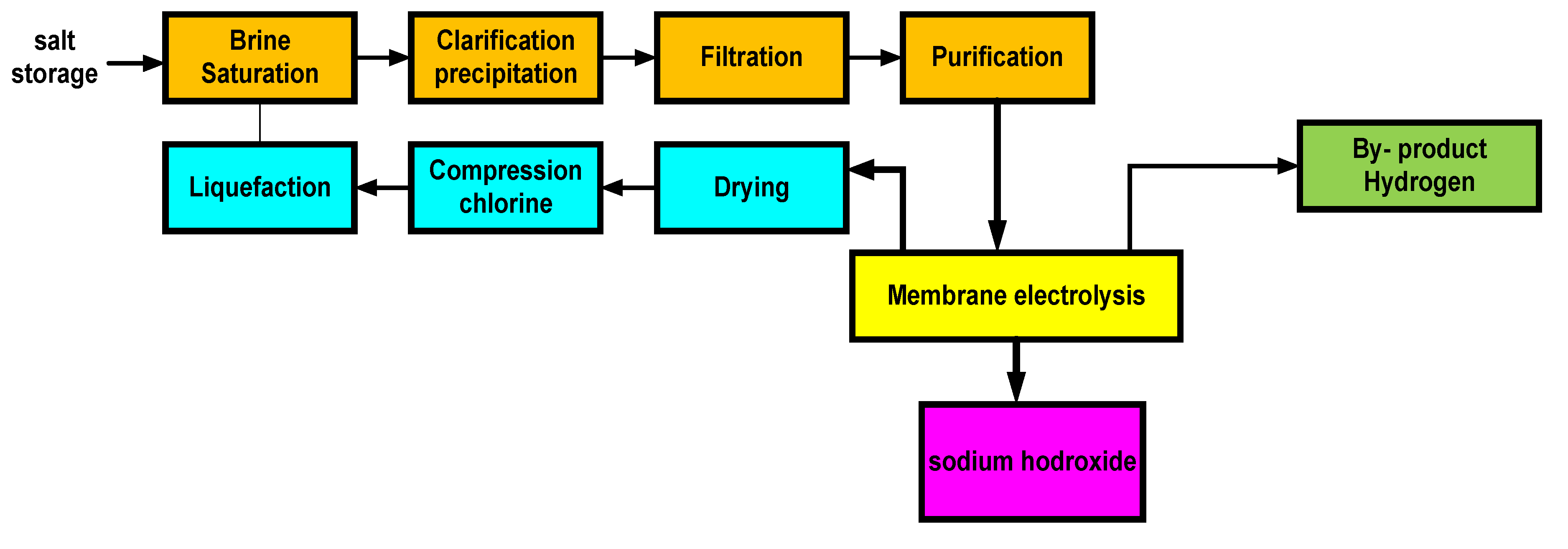
Raw brine contains inorganic impurities such as salts (calcium, magnesium, iron, and sulfate), which can clog ion exchange membranes or damage electrodes, reducing the efficiency of the electrolysis process. Figure 9 shows the block diagram of brine purification and electrolysis, which consists of the following stages: In the precipitation stage, the salts are precipitated by adding carbonate and sodium hydroxide solutions to stirred vessels, forming poorly soluble compounds such as calcium carbonate (CaCO3) and magnesium hydroxide (Mg(OH)2) [112]. After precipitation, these impurities are removed by pressure filtration. The purified brine enters an ion exchange system, which removes the remaining traces of calcium and magnesium ions [113]. The purified brine is fed into the electrolysis cell for the production of chlorine and sodium hydroxide; simultaneously, hydrogen gas is produced as a by-product.

2.4.2. Membrana Cell

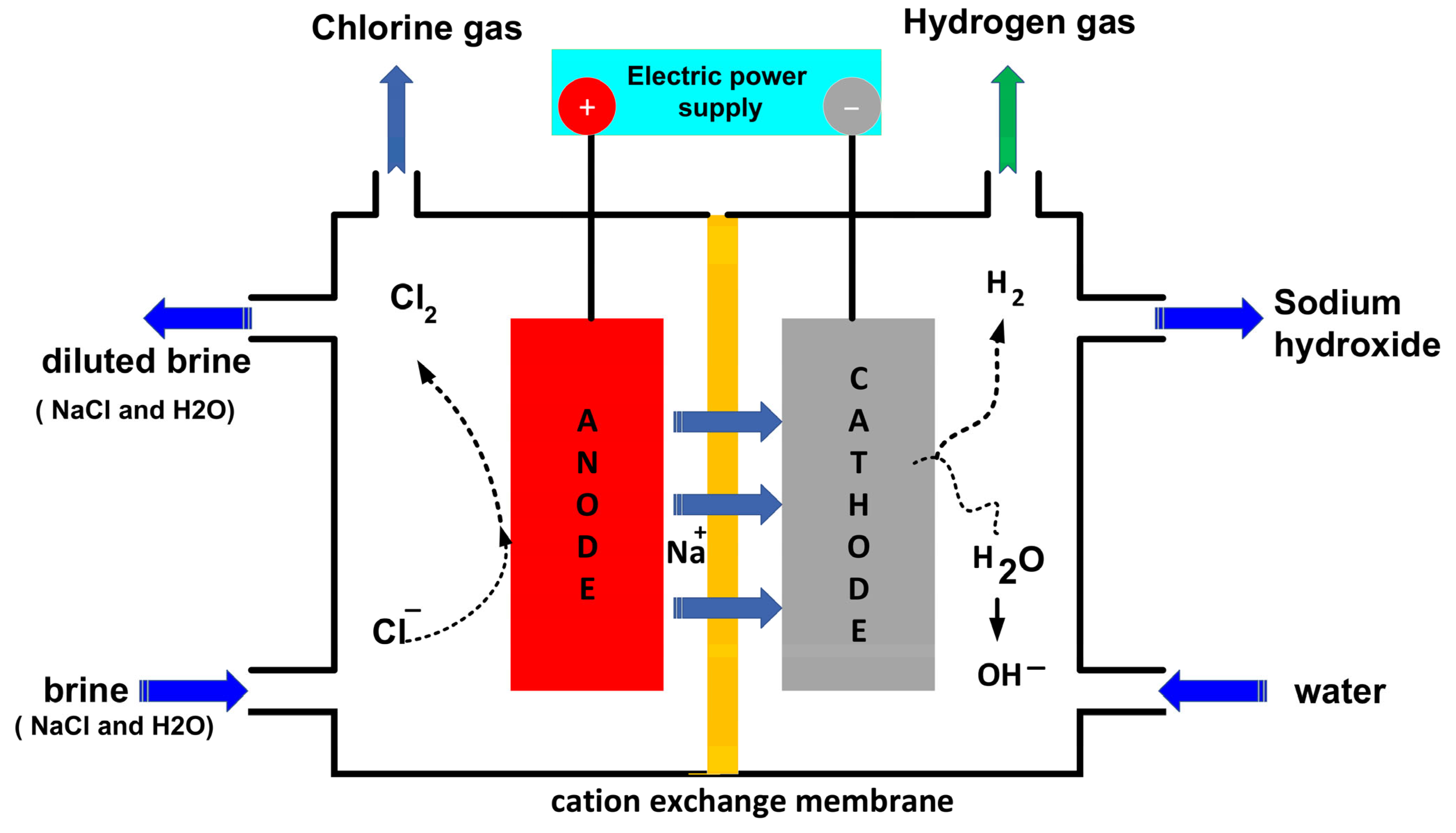
Figure 10 shows a simplified diagram of the membrane cell. A saturated solution of sodium chloride (NaCl) as the electrolyte is introduced into the anode compartment at the bottom of the cell, and the diluted brine exits at the other end of the cell. An electrical voltage is applied across electrodes made of special materials. Chloride ions are oxidized at the anode to form chlorine gas.
2 C l C l 2 ( g ) + 2 e  
Deionized water is introduced into the cathode compartment at the bottom of the cell. Under the effect of the electric current, the water is reduced, forming hydrogen gas and hydroxide ions.
  H 2 O ( l ) + 2 e H 2 ( g ) + O H  
Cation exchange membranes allow sodium ions to flow from the anode compartment to the cathode compartment. These hydroxide ions react with the sodium ions to form sodium hydroxide.
N a + 1 + O H N a O H  
The overall reaction of the sodium chloride electrolysis process is shown in the equation, where chlorine gas, sodium hydroxide solution, and hydrogen gas as a by-product are obtained.
2 N a C l ( a q ) + 2 H 2 O ( l ) C l 2 ( g ) + 2 N a O H ( a q ) + H 2 ( g )  

2.4.3. Mercury Cell

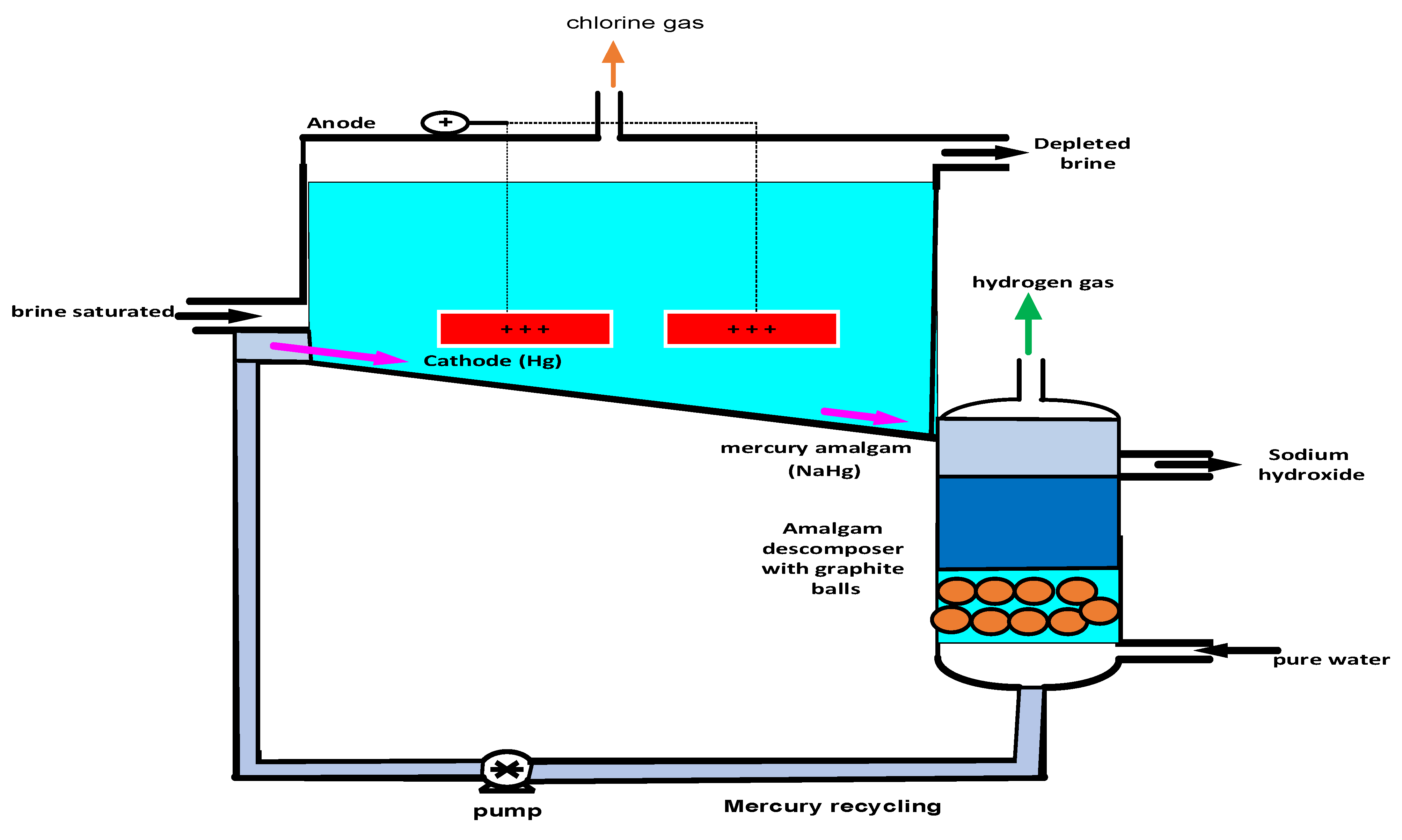
Saturated sodium chloride brine enters the left side of the cell, as shown in Figure 11. Due to its low density, the saturated brine floats on a thin layer of mercury (cathode) [115]. In the amalgamation process, the electrolysis of the sodium chloride solution releases chlorine gas at the anode. The anode (positive pole) consists of horizontally arranged titanium plates coated with ruthenium. The reactions in the electrolyzer are as follows.
2 C l C l 2 ( g ) + 2 e  
The negative pole is a film of liquid mercury that flows along the bottom of the cell, acting as a cathode. The sodium formed immediately dissolves in mercury to form sodium amalgam.
2 N a + + 2 H g + 2 e 2 N a H g  
Next, the amalgam is treated with water in a container, forming sodium hydroxide, hydrogen, and mercury. The mercury is recycled in the process.
2 N a H g + 2   H 2 O 2 N a O H ( a q ) + H 2 ( g ) + 2 H g ( l )  
The overall reaction in the cell is shown in the following equation
2 N a C l ( a q ) + 2 H 2 O ( l ) C l 2 ( g ) + 2 N a O H ( a q ) + H 2 ( g )  
In chlor-alkali plants (where high-purity H2 is obtained as a by-product), the use of an alkaline fuel cell system may be a viable solution for recovery. Previous research has reported that the chlor-alkali process produces substantial amounts of hydrogen as a by-product, which is subsequently wasted and discharged into the environment. They advocate the implementation of a hydrogen boiler, designed to produce steam at a rate of 28 T/h, at a pressure of 25 bar and 250 °C, together with a fuel cell to generate 7.6 MW of electrical energy, as well as 3.83 m3/h of deionized water [49]. In addition, H2 boiler systems can generate half of the steam required in a chlor-alkali plant [116]. According to recent studies, the cost of producing hydrogen using cation exchange membrane technology is around (1.9–2) USD/kgH2, which represents a very competitive economy and environmental benefits compared to mercury cells, which have been gradually replaced due to their toxicity and high operating costs [117].

2.5. Water Purification

For hydrogen production, pure water is the main reactant. According to the stoichiometry of the reaction, 9 kg of water must be consumed to produce 1 kg of hydrogen (9 kg H2O/kg H2) and 8 kg of oxygen [118]. If losses and additional water consumption of 25% for cleaning the equipment are included, this actual water consumption is approximately 14 kgH2O/kg H2 [119]. High-purity water is required as input to the electrolyzers, as impurities can affect the reaction by depositing on the electrolyzers, electrode surfaces, or membrane [59]. Water supplies can come from various sources, such as surface water, industrial wastewater, groundwater, and seawater; however, proper water treatment is required. Each electrolysis system features a water purification unit that ensures the required low conductivity (μS/cm), purifying the feed water to a completely deionized level. However, PEM electrolysis in particular may require lower conductivities (<0.1 μS/cm) [120]. Most studies assumed reverse osmosis (RO) integrated with ion exchange (IX) as the water purification method to achieve conductivities lower than 1 μS/cm. Electrodeionization (EDI) represents an emerging technological synergy that integrates the principles of electrodialysis (ED) and ion exchange (IX) processes. This technology is characterized by its energy efficiency and wide applicability in water purification, achieving a permeate conductivity of 0.6 μS/cm [121]. The typical electrical conductivity of EDI dilute is 0.06–0.1 µS/cm [56]. Previous findings suggest that water produced by membrane distillation meets the conductivity requirements for alkaline electrolyzers (≤5 μS/cm), but not for PEM electrolyzers (≤0.1 μS/cm) [32]. Previous studies, such as the one by Rathi and Kumar [122] reported that an RO-electrodeionization configuration can produce water with conductivity levels between 0.3 and 0.4 μS/cm. While this is acceptable for alkaline electrolyzers, PEM electrolyzers require a conductivity of ≤0.1 μS/cm. Previous studies have reported that the formation of deposits (Ca and Mg hydroxides and carbonates) and accumulation between the cathode/PEM interface could result in an increasingly smaller contact area, generating higher local current densities that could eventually cause stress and membrane failure [123]. The treatment process for obtaining ultrapure water consists of several stages, as shown in Figure 12. First, the water undergoes pretreatment, which includes various processes depending on the source of the water and the technology used. Ultrafiltration (UF) is used to remove total suspended solids (TSS), turbidity, bacteria, and total organic carbon (TOC). Reverse osmosis (RO) removes total dissolved solids (TDS), and mixed bed ion exchange (IXMB) systems replace impurity ions with water-forming ions. Therefore, most electrolyzers include a process for obtaining ultrapure water as part of the system.
As hydrogen emerges as a viable solution in the context of the global energy transition, water demand will increasingly serve as a critical determinant of the sustainability of hydrogen production.
SMR (without/with CCS): SMR requires steam as a reactant, with the overall stoichiometric reaction indicating about 4.5 kg of water is needed per kg of hydrogen produced. Additional water is used for steam production and system cooling, which can significantly increase total water consumption [119].
The stoichiometric water consumption figure (~9 kg/kg H2) is a standard technical reference cited numerous times in the academic literature. One review highlights a water consumption of between 17 and 23 kg/kg H2, depending on the electrolyzer conditions and the feedwater source [124]. Table 4 shows a comparison of water use in hydrogen production by steam methane reforming (SMR without CCS and SMR with CCS) and electrolysis (PEM) and carbon dioxide emissions per kilogram of hydrogen produced.

2.6. Types of Hydrogen Colors

Hydrogen can be produced in different ways, each with a different environmental impact, generally associated with a “color” attribute. Currently, different colors are used to classify hydrogen according to CO2 emissions related to the production method [127]. The importance attributed to each shade of hydrogen depends on the methodologies used in its production, the energy resources used, and the amounts of pollutant emissions generated (carbon intensity) [128]. Hydrogen can be classified into three types: green hydrogen, blue hydrogen, and gray hydrogen. Green hydrogen, also known as low-carbon hydrogen, is produced by electrolysis of water using electricity from renewable energy sources (wind, solar, or hydroelectric) [129]. Blue hydrogen is based on production from fossil fuels, but with a carbon capture, utilization, and storage (CCUS) system [20]. Blue hydrogen also uses SMR but incorporates carbon capture and storage (CCS) technology to reduce carbon dioxide emissions by approximately 90% [130]. Hydrogen derived from fossil fuels with carbon capture and storage (CCS) is called gray hydrogen. When CCS technologies are used in the production process, the category of hydrogen changes from gray to blue. Gray hydrogen refers to hydrogen produced by steam methane reforming, partial oxidation, or autothermal reforming. Currently, most of the hydrogen produced is gray hydrogen.

2.7. Carbon Footprint Assessments

They highlight that electrolysis powered by renewable energy achieves near-zero emissions (~0 kg CO2/kg H2). In contrast, steam reforming without carbon capture generates significant emissions (~9000–12,000 g CO2/g H2). Table 5 shows the grams of carbon dioxide per gram of hydrogen using different production technologies. It also shows the price in dollars per kilogram of hydrogen production.

2.8. Hydrogen Use

Hydrogen has many versatile uses and is an indispensable component in the decarbonization of a large number of industries. Global hydrogen consumption has grown steadily, from 86 Mt in 2019 to an estimated 100 Mt in 2024 [14]. This growth highlights the increasing importance of hydrogen in various industrial sectors, such as oil refining, steel production, and the chemical industry, where it is essential for various processes. Table 6 shows the various applications of hydrogen in different sectors.

2.9. Hydrogen Transport

Despite the recognized demand for renewable hydrogen, the transport infrastructure for hydrogen is currently limited, and the best way to transport it still raises several open questions [146]. Transporting hydrogen from production plants to end users at the lowest possible cost will be key to the success of the green economy. Hydrogen gas can be transported through pipelines, just like natural gas. Before injection, hydrogen is mechanically compressed to the operating pressure of the pipeline, which is usually higher than the outlet pressure of the electrolyzers [147]. As with natural gas pipelines, a mature hydrogen pipeline system with transmission and distribution networks also requires metering stations, control valves, and gate valves to manage flows and ensure distribution to end users [148]. However, the transportation of pure hydrogen requires improvements in materials and infrastructure to address the risks of embrittlement and leaks. In addition, hydrogen can cause metal embrittlement, especially in high-pressure systems, which affects the integrity of pipes and storage tanks [149]. Liquid hydrogen can be transported in super-insulated cryogenic tankers over distances of more than 1600 km [150]. Previous studies have highlighted that one of the challenges of transporting liquid hydrogen is the possibility of evaporation during delivery. Industries has designed ships capable of transporting up to 160,000 m3 of H2, leveraging its experience in liquefied natural gas transportation [151].

3. Conclusions

This review has examined the main hydrogen production technologies, such as alkaline electrolysis, proton exchange membrane (PEM) electrolysis, and anion exchange membrane (AEM) electrolysis, as well as hydrogen production as a by-product in sodium chloride electrolysis processes using membranes and mercury cells. Knowledge from recent scientific articles published in databases related to the subject has been integrated. Alkaline electrolysis is a well-established and commercially mature technology widely used for hydrogen production. PEM electrolysis produces high-purity hydrogen suitable for fuel cells and industrial applications, emitting only oxygen as a by-product. However, the technology relies on noble metal catalysts such as platinum and iridium, which are too expensive and increase the cost of investment. PEM electrolysis is considered highly sustainable, especially when combined with renewable energy sources, contributing to the production of green hydrogen. AEM electrolysis is a combination of alkaline and PEM technologies that operates in alkaline media without using precious metals. Current challenges include lower performance compared to conventional technologies due to limitations of the membrane and electrode assembly. Environmental legislation and pressure for cleaner production methods mean that current trends favor membrane technologies over mercury cells for the production of hydrogen as a by-product. One of the essential inputs for the proper functioning of all electrolytic hydrogen production technologies is ultrapure water.
Future research should focus on the use of seawater and wastewater as feedwater sources to reduce dependence on freshwater and improve the sustainability of green hydrogen production. Constant innovation in the development of catalysts (yolk-shell nanostructured catalysts), membrane materials, and electrolyzer design is essential for advancing these technologies toward cost-effective, sustainable large-scale hydrogen production, which is essential for the transition to a low-carbon energy future.

Author Contributions

Conceptualization, J.T.M.C. and L.C.-V.; methodology, J.T.M.C., C.A.-D., O.R.-T., D.G.-H. and J.M.-P.; software, C.R.-A.; data curation, P.M.-V. and C.S.-M.; writing—original draft preparation, W.C.-S., J.M.-P. and C.A.-D.; writing—review and editing, J.T.M.C., L.C.-V., D.G.-H., N.H.-E. and O.R.-T.; supervision, J.M.-P., C.R.-A. and C.S.-M.; funding acquisition, J.T.M.C. and C.A.-D. All authors have read and agreed to the published version of the manuscript.

Funding

This research was funded by National University of Callao in Lima Peru.

Institutional Review Board Statement

Not applicable.

Informed Consent Statement

Not applicable.

Data Availability Statement

The original contributions of this study are included in the article. For further information, please contact the corresponding author.

Acknowledgments

The authors would like to thank the Universidad Nacional del Callao de Lima (Peru), especially the Vice-Rector of Research of the UNAC, for funding the publication of this article. The authors are grateful for the use of AI-assisted technologies, including SCISPACE and PERPLEXITY which facilitated the paraphrasing process.

Conflicts of Interest

The authors declare that they have no conflicts of interest.

Nomenclature

AEMAnion exchange membrane
PEMProton exchange membrane
CCSCarbon capture and storage
KOHPotassium hydroxide
UFUltrafiltration
ROReverse osmosis
IXMBIon exchange mixed bed
EDIElectrodeionization
GHGHigh greenhouse gas

References

  1. Xia, W.; Zhang, J.; Xu, G.; Jin, T.; Wang, Q.; Jiao, L. Recent advances and challenges in single-atom catalysts for proton exchange membrane water electrolysis. Next Mater. 2025, 8, 100553. [Google Scholar] [CrossRef]
  2. Roucham, B.; Zaghdoud, O. Mapping Green Hydrogen and Renewable Energy Research in Extended BRICS (Brazil, Russia, India, China, South Africa and Others): A Bibliometric Approach with a Future Agenda. Hydrogen 2025, 6, 33. [Google Scholar] [CrossRef]
  3. Kovač, A.; Paranos, M.; Marciuš, D. Hydrogen in energy transition: A review. Int. J. Hydrogen Energy 2021, 46, 10016–10035. [Google Scholar] [CrossRef]
  4. Li, X.; Ye, T.; Meng, X.; He, D.; Li, L.; Song, K.; Jiang, J.; Sun, C. Advances in the Application of Sulfonated Poly(Ether Ether Ketone) (SPEEK) and Its Organic Composite Membranes for Proton Exchange Membrane Fuel Cells (PEMFCs). Polymers 2024, 16, 2840. [Google Scholar] [CrossRef]
  5. Chi, J.; Yu, H. Water electrolysis based on renewable energy for hydrogen production. Chin. J. Catal. 2018, 39, 390–394. [Google Scholar] [CrossRef]
  6. Kim, J.-S.; Lee, D.-C.; Lee, J.-J.; Kim, C.-W. Optimization for maximum specific energy density of a lithium-ion battery using progressive quadratic response surface method and design of experiments. Sci. Rep. 2020, 10, 15586. [Google Scholar] [CrossRef]
  7. Peng, W.; Xu, Y.; Li, G.; Song, J.; Xu, G.; Xu, X.; Pan, Y. Research on typical operating conditions of hydrogen production system with off-grid wind power considering the characteristics of proton exchange membrane electrolysis cell. Glob. Energy Interconnect. 2024, 7, 642–652. [Google Scholar] [CrossRef]
  8. Mandal, M. Novel Electrocatalyst for Alkaline Membrane Water Electrolysis. ChemElectroChem 2020, 7, 4303–4305. [Google Scholar] [CrossRef]
  9. Mostafaeipour, A.; Sedeh, A.S. Investigation of solar energy utilization for production of hydrogen and sustainable chemical fertilizer: A case study. Int. J. Energy Res. 2019, 43, 8314–8336. [Google Scholar] [CrossRef]
  10. Yang, X.; Nielsen, C.P.; Song, S.; McElroy, M.B. Breaking the hard-to-abate bottleneck in China’s path to carbon neutrality with clean hydrogen. Nat. Energy 2022, 7, 955–965. [Google Scholar] [CrossRef]
  11. Edwards, R.L.; Font-Palma, C.; Howe, J. The status of hydrogen technologies in the UK: A multi-disciplinary review. Sustain. Energy Technol. Assess. 2021, 43, 100901. [Google Scholar] [CrossRef]
  12. Azam, A.; Rafiq, M.; Shafique, M.; Yuan, J. Mitigating Carbon Emissions in China: The Role of Clean Energy, Technological Innovation, and Political-Institutional Quality. Front. Environ. Sci. 2022, 10, 814439. [Google Scholar] [CrossRef]
  13. Aravindan, M.; Kumar, P. Hydrogen towards sustainable transition: A review of production, economic, environmental impact and scaling factors. Results Eng. 2023, 20, 101456. [Google Scholar] [CrossRef]
  14. Bhuiyan, M.H.; Siddique, Z. Hydrogen as an alternative fuel: A comprehensive review of challenges and opportunities in production, storage, and transportation. Int. J. Hydrogen Energy 2025, 102, 1026–1044. [Google Scholar] [CrossRef]
  15. Jin, Z.; Gu, D.; Li, P.; Ye, G.; Zhu, H.; Wei, K.; Li, C.; Zhong, W.; Du, W.; Zhu, Q. Artificial intelligence-driven catalyst design for electrocatalytic hydrogen production: Paradigm innovation and challenges in material discovery. Sustain. Chem. Energy Mater. 2025, 2, 100010. [Google Scholar] [CrossRef]
  16. Gomonov, K.; Permana, C.T.; Handoko, C.T. The growing demand for hydrogen: Current trends, sectoral analysis, and future projections. Unconv. Resour. 2025, 6, 100176. [Google Scholar] [CrossRef]
  17. Franchi, G.; Capocelli, M.; De Falco, M.; Piemonte, V.; Barba, D. Hydrogen production via steam reforming: A critical analysis of MR and RMM technologies. Membranes 2020, 10, 10. [Google Scholar] [CrossRef]
  18. Madon, R.H.; Ali, M.F.M.; Khairul, L.; Sarwani, K.L.; Osman, S.A.; Razali, M.A.; Wahab, A.; Baru, P.A. Effect of Reaction Temperature on Steam Methane Reforming’s yield over Coated Nickel Aluminide (Ni 3 Al) Catalyst in Micro Reactor. J. Adv. Res. Fluid Mech. Therm. Sci. 2018, 50, 170–177. [Google Scholar]
  19. Railkar, R.; Kwak, Y.; Vlachos, D.G. Intensifying steam methane reforming and water-gas shift in tandem via rapid pulsed Joule heating. Chem. Eng. J. 2025, 512, 162700. [Google Scholar] [CrossRef]
  20. Davies, W.G.; Babamohammadi, S.; Yang, Y.; Soltani, S.M. The rise of the machines: A state-of-the-art technical review on process modelling and machine learning within hydrogen production with carbon capture. Gas Sci. Eng. 2023, 118, 205104. [Google Scholar] [CrossRef]
  21. Yan, Y.; Thanganadar, D.; Clough, P.T.; Mukherjee, S.; Patchigolla, K.; Manovic, V.; Anthony, E.J. Process simulations of blue hydrogen production by upgraded sorption enhanced steam methane reforming (SE-SMR) processes. Energy Convers. Manag. 2020, 222, 113144. [Google Scholar] [CrossRef]
  22. Gil, A.G.; Wu, Z.; Chadwick, D.; Li, K. Ni/SBA-15 Catalysts for combined steam methane reforming and water gas shift—Prepared for use in catalytic membrane reactors. Appl. Catal. A Gen. 2015, 506, 188–196. [Google Scholar] [CrossRef]
  23. Ribeiro, A.M.; Grande, C.A.; Lopes, F.V.; Loureiro, J.M.; Rodrigues, A.E. A parametric study of layered bed PSA for hydrogen purification. Chem. Eng. Sci. 2008, 63, 5258–5273. [Google Scholar] [CrossRef]
  24. Dziejarski, B.; Krzyżyńska, R.; Andersson, K. Current status of carbon capture, utilization, and storage technologies in the global economy: A survey of technical assessment. Fuel 2023, 342, 127776. [Google Scholar] [CrossRef]
  25. Loachamin, D.; Casierra, J.; Calva, V.; Palma-Cando, A.; Ávila, E.E.; Ricaurte, M. Amine-Based Solvents and Additives to Improve the CO2 Capture Processes: A Review. Chemengineering 2024, 8, 129. [Google Scholar] [CrossRef]
  26. Choi, W.-J.; Seo, J.-B.; Jang, S.-Y.; Jung, J.-H.; Oh, K.-J. Removal characteristics of CO2 using aqueous MEA/AMP solutions in the absorption and regeneration process. J. Environ. Sci. 2009, 21, 907–913. [Google Scholar] [CrossRef]
  27. Bhandari, R.; Trudewind, C.A.; Zapp, P. Life cycle assessment of hydrogen production via electrolysis—A review. J. Clean. Prod. 2014, 85, 151–163. [Google Scholar] [CrossRef]
  28. Lei, Q.; Wang, B.; Wang, P.; Liu, S. Hydrogen generation with acid/alkaline amphoteric water electrolysis. J. Energy Chem. 2019, 38, 162–169. [Google Scholar] [CrossRef]
  29. Kim, S.; Lee, H.I.; Kim, J.; Park, S.; Kim, H.S.; Woo, M.; Kim, J.R.; Lim, D.-H. Simple and efficient fabrication of cathode using activated polyaniline as binder for alkaline water electrolysis. Appl. Surf. Sci. 2025, 693, 162785. [Google Scholar] [CrossRef]
  30. Kumar, S.S.; Lim, H. An overview of water electrolysis technologies for green hydrogen production. Energy Rep. 2022, 8, 13793–13813. [Google Scholar] [CrossRef]
  31. Burnat, D.; Schlupp, M.; Wichser, A.; Lothenbach, B.; Gorbar, M.; Züttel, A.; Vogt, U.F. Composite membranes for alkaline electrolysis based on polysulfone and mineral fillers. J. Power Sources 2015, 291, 163–172. [Google Scholar] [CrossRef]
  32. Husaini, M.A.; Darmanto, P.S.; Juangsa, F.B. Integration of geothermal power plant, water treatment plant, AWE, and PEM electrolyzer for green hydrogen production: A techno-economic study. Next Energy 2025, 7, 100288. [Google Scholar] [CrossRef]
  33. Wang, C.R.; Stansberry, J.M.; Mukundan, R.; Chang, H.-M.J.; Kulkarni, D.; Park, A.M.; Plymill, A.B.; Firas, N.M.; Liu, C.P.; Lang, J.T.; et al. Proton Exchange Membrane (PEM) Water Electrolysis: Cell-Level Considerations for Gigawatt-Scale Deployment. Chem. Rev. 2025, 125, 1257–1302. [Google Scholar] [CrossRef] [PubMed]
  34. Hembach-Stunden, K.; Banning, M.; Becker, L.; Lutz, C.; Matschoss, P.; Klann, U.; Horst, J. Future Installation, Production and Global Trade of Clean Energy Technologies. Sustainability 2024, 16, 10482. [Google Scholar] [CrossRef]
  35. Clapp, M.; Zalitis, C.M.; Ryan, M. Perspectives on current and future iridium demand and iridium oxide catalysts for PEM water electrolysis. Catal. Today 2023, 420, 114140. [Google Scholar] [CrossRef]
  36. Nnabuife, S.G.; Hamzat, A.K.; Whidborne, J.; Kuang, B.; Jenkins, K.W. Integration of renewable energy sources in tandem with electrolysis: A technology review for green hydrogen production. Int. J. Hydrogen Energy 2024, 107, 218–240. [Google Scholar] [CrossRef]
  37. Bayat, A.; Das, P.K.; Saha, G.; Saha, S.C. Proton Exchange Membrane Electrolysis Revisited: Advancements, Challenges, and Two-Phase Transport Insights in Materials and Modelling. Eng 2025, 6, 72. [Google Scholar] [CrossRef]
  38. Zhou, L.; Shao, Y.; Yin, F.; Li, J.; Kang, F.; Lv, R. Stabilizing non-iridium active sites by non-stoichiometric oxide for acidic water oxidation at high current density. Nat. Commun. 2023, 14, 7644. [Google Scholar] [CrossRef]
  39. Khan, M.A.; Al-Attas, T.; Roy, S.; Rahman, M.M.; Ghaffour, N.; Thangadurai, V.; Larter, S.; Hu, J.; Ajayan, P.M.; Kibria, G. Seawater electrolysis for hydrogen production: A solution looking for a problem? Energy Environ. Sci. 2021, 14, 4831–4839. [Google Scholar] [CrossRef]
  40. Ribeiro, C.; Santos, D.M.F. Transitioning Ammonia Production: Green Hydrogen-Based Haber–Bosch and Emerging Nitrogen Reduction Technologies. Clean Technol. 2025, 7, 49. [Google Scholar] [CrossRef]
  41. Mirshekari, G.; Ouimet, R.; Zeng, Z.; Yu, H.; Bliznakov, S.; Bonville, L.; Niedzwiecki, A.; Capuano, C.; Ayers, K.; Maric, R. High-performance and cost-effective membrane electrode assemblies for advanced proton exchange membrane water electrolyzers: Long-term durability assessment. Int. J. Hydrogen Energy 2021, 46, 1526–1539. [Google Scholar] [CrossRef]
  42. Sezer, N.; Bayhan, S.; Fesli, U.; Sanfilippo, A. A comprehensive review of the state-of-the-art of proton exchange membrane water electrolysis. Mater. Sci. Energy Technol. 2025, 8, 44–65. [Google Scholar] [CrossRef]
  43. Wallnöfer-Ogris, E.; Grimmer, I.; Ranz, M.; Höglinger, M.; Kartusch, S.; Rauh, J.; Macherhammer, M.-G.; Grabner, B.; Trattner, A. A review on understanding and identifying degradation mechanisms in PEM water electrolysis cells: Insights for stack application, development, and research. Int. J. Hydrogen Energy 2024, 65, 381–397. [Google Scholar] [CrossRef]
  44. Wallnöfer-Ogris, E.; Poimer, F.; Köll, R.; Macherhammer, M.-G.; Trattner, A. Main degradation mechanisms of polymer electrolyte membrane fuel cell stacks—Mechanisms, influencing factors, consequences, and mitigation strategies. Int. J. Hydrogen Energy 2023, 50, 1159–1182. [Google Scholar] [CrossRef]
  45. Chang, S.H.; Rajuli, M.F. An overview of pure hydrogen production via electrolysis and hydrolysis. Int. J. Hydrogen Energy 2024, 84, 521–538. [Google Scholar] [CrossRef]
  46. Kombargi, A.; Bao, B.; Ellis, E.; Hart, D.P. Life-cycle assessment and cost analysis of hydrogen production via aluminum-seawater reactions. Cell Rep. Sustain. 2025, 2, 100407. [Google Scholar] [CrossRef]
  47. Bodkhe, R.G.; Shrivastava, R.L.; Soni, V.K.; Chadge, R.B. A review of renewable hydrogen generation and proton exchange membrane fuel cell technology for sustainable energy development. Int. J. Electrochem. Sci. 2023, 18, 100108. [Google Scholar] [CrossRef]
  48. Tang, D.; Tan, G.-L.; Li, G.-W.; Liang, J.-G.; Ahmad, S.M.; Bahadur, A.; Humayun, M.; Ullah, H.; Khan, A.; Bououdina, M. State-of-the-art hydrogen generation techniques and storage methods: A critical review. J. Energy Storage 2023, 64, 107196. [Google Scholar] [CrossRef]
  49. A Lee, S.; Kim, J.; Kwon, K.C.; Park, S.H.; Jang, H.W. Anion exchange membrane water electrolysis for sustainable large-scale hydrogen production. Carbon Neutralization 2022, 1, 26–48. [Google Scholar] [CrossRef]
  50. Squadrito, G.; Maggio, G.; Nicita, A. The green hydrogen revolution. Renew. Energy 2023, 216, 119041. [Google Scholar] [CrossRef]
  51. Riaz, M.A.; Trogadas, P.; Aymé-Perrot, D.; Sachs, C.; Dubouis, N.; Girault, H.; Coppens, M.-O. Water electrolysis technologies: The importance of new cell designs and fundamental modelling to guide industrial-scale development. Energy Environ. Sci. 2025, 18, 5190–5214. [Google Scholar] [CrossRef]
  52. El-Shafie, M. Hydrogen production by water electrolysis technologies: A review. Results Eng. 2023, 20, 101426. [Google Scholar] [CrossRef]
  53. Vedrtnam, A.; Kalauni, K.; Pahwa, R. Water Electrolysis Technologies and Their Modeling Approaches: A Comprehensive Review. Eng 2025, 6, 81. [Google Scholar] [CrossRef]
  54. Schmidt, O.; Gambhir, A.; Staffell, I.; Hawkes, A.; Nelson, J.; Few, S. Future cost and performance of water electrolysis: An expert elicitation study. Int. J. Hydrogen Energy 2017, 42, 30470–30492. [Google Scholar] [CrossRef]
  55. Carmo, M.; Fritz, D.L.; Mergel, J.; Stolten, D. A comprehensive review on PEM water electrolysis. Int. J. Hydrogen Energy 2013, 38, 4901–4934. [Google Scholar] [CrossRef]
  56. Kamaroddin, M.F.A.; Sabli, N.; Abdullah, T.A.T.; Siajam, S.I.; Abdullah, L.C.; Jalil, A.A.; Ahmad, A. Membrane-Based Electrolysis for Hydrogen Production: A Review. Membranes 2021, 11, 810. [Google Scholar] [CrossRef]
  57. Miller, H.A.; Bouzek, K.; Hnat, J.; Loos, S.; Bernäcker, C.I.; Weissgaerber, T.; Röntzsch, L.; Meier-Haack, J. Green hydrogen from anion exchange membrane water electrolysis: A review of recent developments in critical materials and operating conditions. Sustain. Energy Fuels 2020, 4, 2114–2133. [Google Scholar] [CrossRef]
  58. Ferreira, A.P.R.A.; Oliveira, R.C.P.; Mateus, M.M.; Santos, D.M.F. A Review of the Use of Electrolytic Cells for Energy and Environmental Applications. Energies 2023, 16, 1593. [Google Scholar] [CrossRef]
  59. Zeng, K.; Zhang, D. Recent progress in alkaline water electrolysis for hydrogen production and applications. Prog. Energy Combust. Sci. 2010, 36, 307–326. [Google Scholar] [CrossRef]
  60. Xu, B.; Yang, Y.; Li, J.; Ye, D.; Wang, Y.; Zhang, L.; Zhu, X.; Liao, Q. A comprehensive study of parameters distribution in a short PEM water electrolyzer stack utilizing a full-scale multi-physics model. Energy 2024, 300, 131565. [Google Scholar] [CrossRef]
  61. Zhao, X.; Shen, Q.; Zhang, Z.; Li, H.; Li, S. Influence of Key Parameters of GDL on Performance of Anion Exchange Membrane Electrolytic Cells. Eng 2025, 6, 111. [Google Scholar] [CrossRef]
  62. Wang, Y.; Wen, C.; Tu, J.; Zhan, Z.; Zhang, B.; Liu, Q.; Zhang, Z.; Hu, H.; Liu, T. The multi-scenario projection of cost reduction in hydrogen production by proton exchange membrane (PEM) water electrolysis in the near future (2020–2060) of China. Fuel 2023, 354, 129409. [Google Scholar] [CrossRef]
  63. Bagheri, B.; Kumagai, H.; Hashimoto, M.; Sugiyama, M. Techno-Economic Assessment of Green Hydrogen Production in Australia Using Off-Grid Hybrid Resources of Solar and Wind. Energies 2025, 18, 3285. [Google Scholar] [CrossRef]
  64. Yin, C.; Jin, L. Estimating Hydrogen Price Based on Combined Machine Learning Models by 2060: Especially Comparing Regional Variations in China. Sustainability 2025, 17, 1049. [Google Scholar] [CrossRef]
  65. Zun, M.T.; McLellan, B.C. Cost Projection of Global Green Hydrogen Production Scenarios. Hydrogen 2023, 4, 932–960. [Google Scholar] [CrossRef]
  66. Pan, J.; Cross, J.L.; Zou, X.; Zhang, B. To tax or to trade? A global review of carbon emissions reduction strategies. Energy Strat. Rev. 2024, 55, 101508. [Google Scholar] [CrossRef]
  67. Jaiswal, K.K.; Chowdhury, C.R.; Yadav, D.; Verma, R.; Dutta, S.; Jaiswal, K.S.; SangmeshB; Karuppasamy, K.S.K. Renewable and sustainable clean energy development and impact on social, economic, and environmental health. Energy Nexus 2022, 7, 100118. [Google Scholar] [CrossRef]
  68. Gielen, D.; Boshell, F.; Saygin, D.; Bazilian, M.D.; Wagner, N.; Gorini, R. The role of renewable energy in the global energy transformation. Energy Strategy Rev. 2019, 24, 38–50. [Google Scholar] [CrossRef]
  69. Emblemsvåg, J. Rethinking the “Levelized Cost of Energy”: A critical review and evaluation of the concept. Energy Res. Soc. Sci. 2024, 119, 103897. [Google Scholar] [CrossRef]
  70. Hassan, Q.; Viktor, P.; Al-Musawi, T.J.; Ali, B.M.; Algburi, S.; Alzoubi, H.M.; Al-Jiboory, A.K.; Sameen, A.Z.; Salman, H.M.; Jaszczur, M. The renewable energy role in the global energy Transformations. Renew. Energy Focus 2024, 48, 100545. [Google Scholar] [CrossRef]
  71. Sachse, D.; Glüsen, A.; Wippermann, K.; Müller, M.; Rau, U.; Peters, R. The Ammonia Adsorption and Desorption Behavior of Nafion. Membranes 2025, 15, 149. [Google Scholar] [CrossRef]
  72. Ito, H.; Maeda, T.; Nakano, A.; Takenaka, H. Properties of Nafion membranes under PEM water electrolysis conditions. Int. J. Hydrogen Energy 2011, 36, 10527–10540. [Google Scholar] [CrossRef]
  73. Lavorante, M.J.; Reynoso, C.Y.; Franco, J.I. Water electrolysis with Zirfon® as separator and NaOH as electrolyte. Desalination Water Treat. 2015, 56, 3647–3653. [Google Scholar] [CrossRef]
  74. Lee, H.I.; Mehdi, M.; Kim, S.K.; Cho, H.S.; Kim, M.J.; Cho, W.C.; Rhee, Y.W.; Kim, C.H. Advanced Zirfon-type porous separator for a high-rate alkaline electrolyser operating in a dynamic mode. J. Membr. Sci. 2020, 616, 118541. [Google Scholar] [CrossRef]
  75. Ali, M.F.; Lee, H.I.; Bernäcker, C.I.; Weißgärber, T.; Lee, S.; Kim, S.-K.; Cho, W.-C. Zirconia Toughened Alumina-Based Separator Membrane for Advanced Alkaline Water Electrolyzer. Polymers 2022, 14, 1173. [Google Scholar] [CrossRef]
  76. Luo, X.; Xu, N.; Zhou, Y.; Yang, X.; Yang, W.; Liu, G.; Lee, J.K.; Qiao, J. Porous PVA skin-covered thin Zirfon-type separator as a new approach boosting high-rate alkaline water electrolysis beyond 1000 hours’ lifespan. eScience 2024, 4, 100290. [Google Scholar] [CrossRef]
  77. Chand, K.; Paladino, O. Recent developments of membranes and electrocatalysts for the hydrogen production by anion exchange membrane water electrolysers: A review. Arab. J. Chem. 2023, 16, 104451. [Google Scholar] [CrossRef]
  78. Lange, H.; Klose, A.; Lippmann, W.; Urbas, L. Technical evaluation of the flexibility of water electrolysis systems to increase energy flexibility: A review. Int. J. Hydrogen Energy 2023, 48, 15771–15783. [Google Scholar] [CrossRef]
  79. Kim, J.H.; Jo, H.J.; Han, S.M.; Kim, Y.J.; Kim, S.Y. Recent advances in electrocatalysts for anion exchange membrane water electrolysis: Design strategies and characterization approaches. Energy Mater. 2025, 5, 500099. [Google Scholar] [CrossRef]
  80. Tang, Z.; Wu, B.; Yan, K.; Luo, J.; Haq, M.U.; Zeng, L. Long-term stability for anion exchange membrane water electrolysis: Recent development and future perspectives. Futur. Batter. 2025, 5, 100024. [Google Scholar] [CrossRef]
  81. Zheng, Y.; Colón, L.N.I.; Hassan, N.U.; Williams, E.R.; Stefik, M.; LaManna, J.M.; Hussey, D.S.; Mustain, W.E. Effect of membrane properties on the carbonation of anion exchange membrane fuel cells. Membranes 2021, 11, 102. [Google Scholar] [CrossRef]
  82. Wang, L.; Liu, W.; Sun, H.; Yang, L.; Huang, L. Advancements and Policy Implications of Green Hydrogen Production from Renewable Sources. Energies 2024, 17, 3548. [Google Scholar] [CrossRef]
  83. Segovia-Hernández, J.G.; Hernández, S.; Cossío-Vargas, E.; Juarez-García, M.; Sánchez-Ramírez, E. Green hydrogen production for sustainable development: A critical examination of barriers and strategic opportunities. RSC Sustain. 2024, 3, 134–157. [Google Scholar] [CrossRef]
  84. Jeje, S.O.; Marazani, T.; Obiko, J.O.; Shongwe, M.B. Advancing the hydrogen production economy: A comprehensive review of technologies, sustainability, and future prospects. Int. J. Hydrogen Energy 2024, 78, 642–661. [Google Scholar] [CrossRef]
  85. Eikeng, E.; Makhsoos, A.; Pollet, B.G. Critical and strategic raw materials for electrolysers, fuel cells, metal hydrides and hydrogen separation technologies. Int. J. Hydrogen Energy 2024, 71, 433–464. [Google Scholar] [CrossRef]
  86. Razmjooei, F.; Morawietz, T.; Taghizadeh, E.; Hadjixenophontos, E.; Mues, L.; Gerle, M.; Wood, B.D.; Harms, C.; Gago, A.S.; Ansar, S.A.; et al. Increasing the performance of an anion-exchange membrane electrolyzer operating in pure water with a nickel-based microporous layer. Joule 2021, 5, 1776–1799. [Google Scholar] [CrossRef]
  87. Hassan, Q.; Sameen, A.Z.; Salman, H.M.; Jaszczur, M. Large-scale green hydrogen production using alkaline water electrolysis based on seasonal solar radiation. Energy Harvest. Syst. 2024, 11. [Google Scholar] [CrossRef]
  88. Mazumder, G.C.; Parvez, S.; Zishan, S.R.; Rahman, H. Quantitative Analysis of Green H2 Production Costs: A Comparison between Domestic Developed and Imported Electrolyzers. Emerg. Sci. Innov. 2024, 3, 12–26. [Google Scholar] [CrossRef]
  89. Titheridge, L.J.; Marshall, A.T. Techno-economic modelling of AEM electrolysis systems to identify ideal current density and aspects requiring further research. Int. J. Hydrogen Energy 2024, 49, 518–532. [Google Scholar] [CrossRef]
  90. Krishnan, S.; Koning, V.; de Groot, M.T.; de Groot, A.; Mendoza, P.G.; Junginger, M.; Kramer, G.J. Present and future cost of alkaline and PEM electrolyser stacks. Int. J. Hydrogen Energy 2023, 48, 32313–32330. [Google Scholar] [CrossRef]
  91. Terlouw, T.; Bauer, C.; McKenna, R.; Mazzotti, M. Large-scale hydrogen production via water electrolysis: A techno-economic and environmental assessment. Energy Environ. Sci. 2022, 15, 3583–3602. [Google Scholar] [CrossRef]
  92. Touili, S.; Merrouni, A.A.; El Hassouani, Y.; Amrani, A.-I.; Rachidi, S. Analysis of the yield and production cost of large-scale electrolytic hydrogen from different solar technologies and under several Moroccan climate zones. Int. J. Hydrogen Energy 2020, 45, 26785–26799. [Google Scholar] [CrossRef]
  93. Krishnan, S.; Corona, B.; Kramer, G.J.; Junginger, M.; Koning, V. Prospective LCA of alkaline and PEM electrolyser systems. Int. J. Hydrogen Energy 2024, 55, 26–41. [Google Scholar] [CrossRef]
  94. Wawrzyńczak, A.; Feliczak-Guzik, A. Hydrogen Production Using Modern Photocatalysts. Coatings 2024, 14, 366. [Google Scholar] [CrossRef]
  95. Pokrant, S.; Dilger, S.; Landsmann, S.; Trottmann, M. Size effects of cocatalysts in photoelectrochemical and photocatalytic water splitting. Mater. Today Energy 2017, 5, 158–163. [Google Scholar] [CrossRef]
  96. Jakhar, M.; Kumar, A.; Ahluwalia, P.K.; Tankeshwar, K.; Pandey, R. Engineering 2D Materials for Photocatalytic Water-Splitting from a Theoretical Perspective. Materials 2022, 15, 2221. [Google Scholar] [CrossRef]
  97. Hassaan, M.A.; El-Nemr, M.A.; Elkatory, M.R.; Ragab, S.; Niculescu, V.-C.; El Nemr, A. Principles of Photocatalysts and Their Different Applications: A Review. Top. Curr. Chem. 2023, 381, 31. [Google Scholar] [CrossRef]
  98. Qanugo, K.; Bose, D.; Thakur, K.K. A Review on Photocatalytic Water Splitting. In Proceedings of the 3rd International Conference on Design and Manufacturing Aspects for Sustainable Energy (ICMED-ICMPC 2021), Hyderabad, India, 24–26 December 2021. [Google Scholar] [CrossRef]
  99. Acar, C.; Dincer, I.; Naterer, G.F. Review of photocatalytic water-splitting methods for sustainable hydrogen production. Int. J. Energy Res. 2016, 40, 1449–1473. [Google Scholar] [CrossRef]
  100. Bratovčić, A.; Tomašić, V. Hydrogen Production Through Newly Developed Photocatalytic Nanostructures and Composite Materials. Processes 2025, 13, 1813. [Google Scholar] [CrossRef]
  101. Wu, J.-Y.; Wei, Y.-C.; Torimoto, T.; Chien, Y.-A.; Chen, C.-Y.; Chang, T.-F.M.; Sone, M.; Hsieh, P.-Y.; Hsu, Y.-J. Yolk@Shell Nanostructures for Water Splitting: Current Development and Future Prospects. ACS Mater. Lett. 2024, 6, 4066–4089. [Google Scholar] [CrossRef]
  102. Sun, X.; Han, J.; Guo, R. A Mini Review on Yolk-Shell Structured Nanocatalysts. Front. Chem. 2020, 8, 606044. [Google Scholar] [CrossRef]
  103. Shu, Z.; Zhao, Z.; Zhou, J.; Wang, Y.; Wang, W.; Li, T. Natural molybdenite mineral enhanced polymeric carbon nitride nano-composites for efficient noble-metal-free photocatalytic hydrogen evolution. Mater. Res. Bull. 2021, 136, 111158. [Google Scholar] [CrossRef]
  104. Qiao, F. Photoelectrocatalytic hydrogen production: Hydrogen production principle, performance optimization strategy, application and prospect. Nano Res. Energy 2025, 4, e9120132. [Google Scholar] [CrossRef]
  105. Kumar, M.; Singh, N.K.; Kumar, R.S.; Singh, R. Production of Green Hydrogen through Photocatalysis. Am. Chem. Soc. 2024, 1468, 1–24. [Google Scholar] [CrossRef]
  106. Xue, J.; Yang, Q.; Guan, R.; Shen, Q.; Liu, X.; Jia, H.; Li, Q. High-performance ordered porous Polypyrrole/ZnO films with improved specific capacitance for supercapacitors. Mater. Chem. Phys. 2020, 256, 123591. [Google Scholar] [CrossRef]
  107. Li, K.; Dong, W.J.; Mi, Z. Photoelectrochemical water splitting under concentrated sunlight: Best practices and protocols. Front. Energy Res. 2025, 13, 1550153. [Google Scholar] [CrossRef]
  108. Wang, W.; Wang, H.; Zhu, Q.; Qin, W.; Han, G.; Shen, J.; Zong, X.; Li, C. Spatially Separated Photosystem II and a Silicon Photoelectrochemical Cell for Overall Water Splitting: A Natural–Artificial Photosynthetic Hybrid. Angew. Chem. Int. Ed. Engl. 2016, 55, 9229–9233. [Google Scholar] [CrossRef]
  109. Garcia-Herrero, I.; Margallo, M.; Onandía, R.; Aldaco, R.; Irabien, A. Environmental challenges of the chlor-alkali production: Seeking answers from a life cycle approach. Sci. Total. Environ. 2017, 580, 147–157. [Google Scholar] [CrossRef]
  110. Margallo, M.; Onandía, R.; Aldaco, R.; Irabien, A. When life cycle thinking is necessary for decision making: Emerging cleaner technologies in the chlor-alkali industry. Chem. Eng. Trans. 2016, 52, 475–480. [Google Scholar] [CrossRef]
  111. Zhang, X.; Qian, X.; Xiao, C.; Yin, X.; Wang, X.; Wang, Z.; Yu, H.; Han, Z.; Lin, L. Advancements in purification and holistic utilization of industrial by-product hydrogen: Progress, challenges, and prospects. Green Energy Resour. 2024, 2, 100098. [Google Scholar] [CrossRef]
  112. Khan, J.R.; Muhammad, S.; Feroze, N.; Mustsfa Ali Bukhari Yasir Khurshid, S.; Wahab Malik, A. Brine Puri-fication for Chlor-Alkalis Production Based on Membrane Technology. Pak. J. Eng. Appl. Sci. 2015, 16, 17–24. Available online: https://journal.uet.edu.pk/ojs_old/index.php/pjeas/article/view/67/25 (accessed on 8 September 2025).
  113. Ali, W.; Jiang, C.; Dehghanpour, H. A Critical Review of Produced Water Management Using the Chlor-Alkali Process: Challenges and Future Prospects. Water Environ. Res. 2025, 97, e70124. [Google Scholar] [CrossRef]
  114. Aziz, H.; Ghazali, M.; Yusoff, M.; Hung, Y. Waste Treatment and Management in Chlor-Alkali Industries. In Waste Treatment in the Service and Utility Industries; CRC Press: Boca Raton, FL, USA, 2017; pp. 99–144. [Google Scholar] [CrossRef]
  115. Dincer, I.; Zamfirescu, C. Hydrogen Production by Electrical Energy. In Sustainable Hydrogen Production; Elsevier: Amsterdam, The Netherlands, 2016; pp. 99–161. [Google Scholar] [CrossRef]
  116. Samiee, L.; Goodarzvand-Chegini, F.; Ghasemikafrudi, E.; Kashefi, K. Hydrogen recovery in an industrial chlor-alkali plant using alkaline fuel cell and hydrogen boiler techniques: Techno-economic assessment and emission estimation. J. Renew. Energy Environ. 2021, 18, 49–57. [Google Scholar] [CrossRef]
  117. Islam, T.; Qadir, S.A.; Ali, A.; Khan, M.W. Economic and environmental impact assessment of renewable energy integration: A review and future research directions. Clean. Energy Syst. 2024, 9, 100162. [Google Scholar] [CrossRef]
  118. Beswick, R.R.; Oliveira, A.M.; Yan, Y. Does the Green Hydrogen Economy Have a Water Problem? ACS Energy Lett. 2021, 6, 3167–3169. [Google Scholar] [CrossRef]
  119. Simoes, S.G.; Catarino, J.; Picado, A.; Lopes, T.F.; di Berardino, S.; Amorim, F.; Gírio, F.; Rangel, C.; de Leão, T.P. Water availability and water usage solutions for electrolysis in hydrogen production. J. Clean. Prod. 2021, 315, 128124. [Google Scholar] [CrossRef]
  120. Holst, M.; Aschbrenner, S.; Smolinka, T.; Voglstätter, C.; Grimm, G. Cost Forecast for Low Temperature Electrolysis-Technology Driven Bottom-Up Prognosis for PEM and Alkaline Water Electrolysis Systems; Fraunhofer Institute for Solar Energy Systems ISE: Freiburg, Germany, 2021; 79p. [Google Scholar]
  121. Wood, J.; Gifford, J.; Arba, J.; Shaw, M. Production of ultrapure water by continuous electrodeionization. Desalination 2010, 250, 973–976. [Google Scholar] [CrossRef]
  122. Rathi, B.S.; Kumar, P.S. Electrodeionization theory, mechanism and environmental applications. A review. Environ. Chem. Lett. 2020, 18, 1209–1227. [Google Scholar] [CrossRef]
  123. Grimmig, R.; Gillemot, P.; Stucki, S.; Günther, K.; Baltruschat, H.; Witzleben, S. Operating an ozone-evolving PEM electrolyser in tap water: A case study of water and ion transport. Sep. Purif. Technol. 2022, 292, 121063. [Google Scholar] [CrossRef]
  124. Lin, N.; Arzumanyan, M.; Calzado, E.R.; Nicot, J.-P. Water Requirements for Hydrogen Production: Assessing Future Demand and Impacts on Texas Water Resources. Sustainability 2025, 17, 385. [Google Scholar] [CrossRef]
  125. Henriksen, M.S.; Matthews, H.S.; White, J.; Walsh, L.; Grol, E.; Jamieson, M.; Skone, T.J. Tradeoffs in Life Cycle Water Use and Greenhouse Gas Emissions of Hydrogen Production Pathways. Int. J. Hydrogen Energy 2023, 49, 1221–1234. [Google Scholar] [CrossRef]
  126. Anaya, K.; Oni, A.O.; Kumar, A. Water intensity for hydrogen production with and without carbon capture and sequestration. J. Environ. Chem. Eng. 2025, 13, 117572. [Google Scholar] [CrossRef]
  127. Noussan, M.; Raimondi, P.P.; Scita, R.; Hafner, M. The role of green and blue hydrogen in the energy transition—A technological and geopolitical perspective. Sustainability 2021, 13, 298. [Google Scholar] [CrossRef]
  128. Ajanovic, A.; Sayer, M.; Haas, R. The economics and the environmental benignity of different colors of hydrogen. Int. J. Hydrogen Energy 2022, 47, 24136–24154. [Google Scholar] [CrossRef]
  129. Reichartz, T.; Jacobs, G.; Rathmes, T.; Blickwedel, L.; Schelenz, R. Optimal position and distribution mode for on-site hydrogen electrolyzers in onshore wind farms for a minimal levelized cost of hydrogen (LCoH). Wind. Energy Sci. 2024, 9, 281–295. [Google Scholar] [CrossRef]
  130. Bauer, C.; Treyer, K.; Antonini, C.; Bergerson, J.; Gazzani, M.; Gencer, E.; Gibbins, J.; Mazzotti, M.; McCoy, S.T.; McKenna, R.; et al. On the climate impacts of blue hydrogen production. Sustain. Energy Fuels 2022, 6, 66–75. [Google Scholar] [CrossRef]
  131. Dumančić, A.; Vlahinić, N.; Skok, M. Replacing Gray Hydrogen with Renewable Hydrogen at the Consumption Location Using the Example of the Existing Fertilizer Plant. Sustainability 2024, 16, 6437. [Google Scholar] [CrossRef]
  132. Patel, G.H.; Havukainen, J.; Horttanainen, M.; Soukka, R.; Tuomaala, M. Climate change performance of hydrogen production based on life cycle assessment. Green Chem. 2024, 26, 992–1006. [Google Scholar] [CrossRef]
  133. Díaz, M.T.M.; Oróstica, H.C.; Guajardo, J. Economic Analysis: Green Hydrogen Production Systems. Processes 2023, 11, 1390. [Google Scholar] [CrossRef]
  134. Camargo, L.; Comas, D.; Escorcia, Y.C.; Alviz-Meza, A.; Caballero, G.C.; Portnoy, I. Bibliometric Analysis of Global Trends around Hydrogen Production Based on the Scopus Database in the Period 2011–2021. Energies 2023, 16, 87. [Google Scholar] [CrossRef]
  135. Alizadeh, S.M.; Khalili, Y.; Ahmadi, M. Comprehensive Review of Carbon Capture and Storage Integration in Hydrogen Production: Opportunities, Challenges, and Future Perspectives. Energies 2024, 17, 5330. [Google Scholar] [CrossRef]
  136. Ali, D.N.H.A.P.H.O.; Suhaimi, H.; Abas, P.E. Membrane-Based Hydrogen Production: A Techno-Economic Evaluation of Cost and Feasibility. Hydrogen 2025, 6, 9. [Google Scholar] [CrossRef]
  137. Galusnyak, S.; Petrescu, L.; Cormos, C.-C. Techno-economic and environmental assessment of hydrogen production based on natural gas steam reforming process. Stud. Univ. Babeș-Bolyai Chem. 2020, 65, 7–19. [Google Scholar] [CrossRef]
  138. Roy, R.; Antonini, G.; Hayibo, K.S.; Rahman, M.; Khan, S.; Tian, W.; Boutilier, M.S.; Zhang, W.; Zheng, Y.; Bassi, A.; et al. Comparative techno-environmental analysis of grey, blue, green/yellow and pale-blue hydrogen production. Int. J. Hydrogen Energy 2025, 116, 200–210. [Google Scholar] [CrossRef]
  139. Bento, C.; Lopes, T.F.; Rodrigues, P.; Gírio, F.; Silva, C. Biogas reforming as a sustainable solution for hydrogen production: Comparative environmental metrics with steam-methane reforming and water electrolysis in the Portuguese context. Int. J. Hydrogen Energy 2024, 66, 661–675. [Google Scholar] [CrossRef]
  140. European Union. Estimation of the Global Average GHG Emission Intensity of Hydrogen Production; JRC Technical Report; European Union: Brussels, Belgium, 2023. [Google Scholar] [CrossRef]
  141. Weinand, J.M.; McKenna, R.; Kleinebrahm, M.; Scheller, F.; Fichtner, W. The impact of public acceptance on cost efficiency and environmental sustainability in decentralized energy systems. Patterns 2021, 2, 100301. [Google Scholar] [CrossRef]
  142. Badruzzaman, A.; Karagoz, S.; Eljack, F. Sustainable-green hydrogen production through integrating electrolysis, water treatment and solar energy. Front. Chem. Eng. 2025, 7, 1526331. [Google Scholar] [CrossRef]
  143. Roucham, B.; Lefilef, A.; Zaghdoud, O.; Mohammed, K.S. The evolution of green hydrogen in renewable energy research: Insights from a bibliometric perspective. Energy Rep. 2025, 13, 576–593. [Google Scholar] [CrossRef]
  144. Nasser, M.; Megahed, T.F.; Ookawara, S.; Hassan, H. A review of water electrolysis–based systems for hydrogen production using hybrid/solar/wind energy systems. Environ. Sci. Pollut. Res. 2022, 29, 86994–87018. [Google Scholar] [CrossRef]
  145. Agyekum, E.B.; Ampah, J.D.; Wilberforce, T.; Afrane, S.; Nutakor, C. Research Progress, Trends, and Current State of Development on PEMFC-New Insights from a Bibliometric Analysis and Characteristics of Two Decades of Research Output. Membranes 2022, 12, 1103. [Google Scholar] [CrossRef]
  146. Lipiäinen, S.; Lipiäinen, K.; Ahola, A.; Vakkilainen, E. Use of existing gas infrastructure in European hydrogen economy. Int. J. Hydrogen Energy 2023, 48, 31317–31329. [Google Scholar] [CrossRef]
  147. Hassan, M.A.; El-Amary, N.H. Economic and technical analysis of hydrogen production and transport: A case study of Egypt. Sci. Rep. 2025, 15, 9002. [Google Scholar] [CrossRef]
  148. Lipiäinen, S.; Vakkilainen, E. Feasibility of the transportation options of renewable hydrogen for moderate distances: Insights from a remote production in Finland. Energy Convers. Manag. X 2025, 27, 101158. [Google Scholar] [CrossRef]
  149. Jia, G.; Lei, M.; Li, M.; Xu, W.; Li, R.; Lu, Y.; Cai, M. Hydrogen embrittlement in hydrogen-blended natural gas transportation systems: A review. Int. J. Hydrogen Energy 2023, 48, 32137–32157. [Google Scholar] [CrossRef]
  150. Chung, S.-M.; Jeon, G.-M.; Park, J.-C. Numerical approach to analyze fluid flow in a type C tank for liquefied hydrogen carrier (part 1: Sloshing flow). Int. J. Hydrogen Energy 2022, 47, 5609–5626. [Google Scholar] [CrossRef]
  151. Amjath, M.; Eljack, F.; Haouari, M. Optimizing post-production alternate hydrogen supply chain pathways—An integrated TEA and LCA approach. Int. J. Hydrogen Energy 2025, 100, 1421–1443. [Google Scholar] [CrossRef]
Figure 1. Block diagram of the steam methane reforming process.
Sustainability 17 08367 g001
Figure 2. Simplified process flow diagram of chemical absorption for CO2 capture. where absorption column (T-101); stripper column (T-102) and heat exchangers(E-101, E-102 and E-103).
Sustainability 17 08367 g002
Figure 3. Block diagram of the electrolysis process.
Sustainability 17 08367 g003
Figure 4. Alkaline electrolysis.
Sustainability 17 08367 g004
Figure 5. Alkaline water electrolysis process flow diagram.
Sustainability 17 08367 g005
Figure 6. Flow diagram of the electrolysis process by proton exchange membrane.
Sustainability 17 08367 g006
Figure 7. Diagram of the proton exchange membrane water electrolysis cell (PEMWE).
Sustainability 17 08367 g007
Figure 8. Schematic representation of the AEM water electrolysis cell.
Sustainability 17 08367 g008
Figure 9. Illustrates the BFD (Block Flow Diagram) of the chlor-alkali plant.
Sustainability 17 08367 g009
Figure 10. Process flow diagram for membrane cell process [114].
Sustainability 17 08367 g010
Figure 11. Mercury cell process flow diagram.
Sustainability 17 08367 g011
Figure 12. Schematic diagram of the water treatment plant for hydrogen production by PEM. UF = ultrafiltration; RO = reverse osmosis; EDI = electrodeionization; IXMB = ion exchange mixed be.
Sustainability 17 08367 g012
Table 2. Additional raw materials for water electrolysis.
Electrolysis TechnologyAdditional Raw Materials/ComponentsRemarks/NotesReferences (R)
PEM (Proton Exchange Membrane)Anode catalyst: typically IrO2 (Iridium oxide)—Cathode catalyst: typically Pt (Platinum)—Acidic membrane electrolyte (Nafion membrane)Noble metal catalysts (Ir, Pt) are critical; acidic membrane is a solid electrolyte; pure water feed[57]
WE (Alkaline Water Electrolysis)Alkaline electrolyte (e.g., KOH solution)—Electrodes: typically Ni-based or other transition metals as catalysts—Supporting electrolyte materialsMature, low cost, highly safe technology; uses liquid alkaline electrolyte; intermittent renewable energy integration is common[87]
AEM (Anion Exchange Membrane Electrolysis)Anion exchange membrane with quaternary ammonium ion exchange groups (e.g., A201 and A901 types of Tokuyama membranes)—Catalyst: PGM-free transition metal catalysts (Ni(OH)2, Fe(OOH), NiCoOx, CuCoOx, Ni/(CeO2-La2O3)/C)—Low concentration alkaline solutions or pure water feed—supporting electrolytes such as 1% K2CO3, KHCO3—Membrane binder materials (quaternized polystyrene)Combines advantages of AWE and PEM; uses lower cost membranes and catalysts; electrolyte can be pure water or diluted alkaline solutions; research on catalysts and membrane stability ongoing; no corrosive liquid electrolyte[57]
Table 3. Capital and operating costs of water electrolysis.
ParameterAlkaline Water Electrolysis (AWE)Proton Exchange Membrane (PEM) ElectrolysisAnion Exchange Membrane (AEM) ElectrolysisR
Cost of capital (Electrolyzer Stack, USD/kW)Approx. 270 (current), target < 100 by 2050Approx. 1500–2200 (current)Approximately (USD 444–USD 460/kW), Installation costs for AEM electrolysis systems ranging from 1 MW to 5 MW[57]
Cost of capital (USD/kW)USD 800–1200/kW (typical large scale)USD 1500–2200/kW (higher due to the materials)Currently TRL 6, ~USD 500–1000/kW, expected to decrease[88]
Operating CostElectricity cost assumption ~USD 0.03/kWh; chemical costs due to KOH electrolyte are notableLower electricity consumption than AWE, no chemical costsPotential cost advantage with cheaper catalysts and stainless steel components, but technology less mature[91]
Annual Fixed CostsExample: USD 228,115 per year (developed AE) USD 191 990 per year (PEM) For 1 MW plants, costs range from approximately USD 922 and USD 1279 kW.[57]
Hydrogen Production CostAround USD 3.64–USD 4.76/kg (varies by scale and location)Typically USD 4–USD 6/kg but can decrease to ~USD 2.15/kg in 10 years due to tech learning0.62–0.89 (USD/kg H2) Future and far-future projected costs per National Renewable Energy Lab (NREL) analysis[90]
Electrical efficiency (kWh/kg H2)50–78 (system), objective < 45 para 205050–60 (improvement with higher current density)Objective comparable to PEM, with ongoing R&D to achieve voltage efficiency > 70%[92]
Current density (A/cm2)0.2–0.8 (present), objective > 2Generally around 2>1 currently, with the aim of reaching a higher level to match the PEM[57]
Purity of hydrogen99.9–99.9998%, objective > 99.9999High purity (99.999%)Comparable to PEM purity objectives[88]
Raw materialsNickel-based, widely availableContains expensive Pt, Ir, and Ti as critical componentsNickel-based raw materials, more abundant and cheaper[92]
System footprintBigger20–24% lower on similar scalesPotentially compact design as PEM, but requires expansion[93]
Table 4. Water consumption (kg) per kilogram of hydrogen produced.
Hydrogen Production Route(kg Water/kg H2)(kg CO2/kg H2)Environmental CompensationR
Steam methane reforming (SMR) without CCS15–40 (primarily cooling water)~10.4–12.4Moderate water use, high emissions of GHG[125]
SMR with CCS18–45Reduction in GEI emissions compared to no CCSCarbon capture and storage reduces emissions, but increases energy and water consumption.[124]
Electrolysis (PEM) grid electricity220~280~25–31Very high-water
consumption, high dependence on electricity source; high GHG levels if grid electricity is used.
[126]
Electrolysis (PEM) renewable electricity (solar/wind)(~30–40)~2–3Much lower water and
GEG footprint when using renewable energy.
[124]
Table 5. Environmental impact of green, blue, and gray hydrogen production (g CO2/g H2) and price per kg of hydrogen.
HydrogenTechnologyNotes/StatusUSD/kg H2g de CO2/g de H2Ref
GreenElectrolysis using renewables (wind/solar)Cleanest, currently expensive2.3–7.4 [131]
3.6–5.8 [30]
~0.3 g–1.5 g CO2/g H2[132]
1.6 g–1.8 g CO2/g de H2[132]
2.5–9.5 [133]~0 g CO2/g H2[134]
0 g CO2/g H2 [36]
BlueSMR with carbon capture and storage (CCS)Lower emissions, higher cost1.8–4.7 [132]
1.5–2.9 [30]
(200–300) g CO2/g de H2[135]
1000–4000[132]
~8 [136]410[137]
1000–2000[135]
GreySteam Methane Reforming (SMR) from natural gasMost common, high emissions1–2 [138]
0.7–2.5 [133]
1–2.1 [30]
8000–9000[139]
9000[20]
(1000–1200) g CO2/g H2[140]
9000–11,000[141]
9000–13,000[138]
Table 6. Uses of hydrogen.
Category of UseDescriptionR
Energy carrier and storageSeasonal energy storage to complement intermittent wind and solar power.[142]
Industrial raw materialFertilizer production, refining, and chemical manufacturing.[143]
Power generationFuel cells for electricity generation in stationary and portable applications.[144]
heating mediumDecarbonizing building heating, including residential and commercial heating systems industrial process heating, boiler technologies[145]
Transport fuelCars, buses, trucks, trains, ships, and potentially aircraft powered by hydrogen fuel cells.[143]
Applications in spaceRocket fuel for propulsion (green hydrogen as a clean combustion propellant)
Disclaimer/Publisher’s Note: The statements, opinions and data contained in all publications are solely those of the individual author(s) and contributor(s) and not of MDPI and/or the editor(s). MDPI and/or the editor(s) disclaim responsibility for any injury to people or property resulting from any ideas, methods, instructions or products referred to in the content.