Abstract
Hydrodynamic cavitation is one of the most promising technologies for sustainable process intensification in the food, nutraceutical, and environmental sectors, due to its ability to generate highly localized and intense implosions. Venturi-type devices, known for their simplicity and efficiency, are widely used for non-thermal extraction, microbial inactivation, and cellular disruption. However, the effectiveness of cavitation critically depends on internal geometry—particularly the perimeter-to-area ratio (P/A), which influences both pressure gradient distribution and the density of nucleation sites. In this context, an innovative configuration based on the Reuleaux triangle is proposed, allowing for a significant increase in the P/A ratio compared to conventional circular-section devices. This theoretical study extends the Navier–Stokes and Rayleigh–Plesset models to describe bubble dynamics and assess the influence of geometric and rotational variants (VRAt) on the localization and intensity of cavitation collapse. The results suggest that optimized internal geometries can reduce treatment times, increase selectivity, and improve the overall energy efficiency of cavitation processes, offering strong potential for advanced and sustainable industrial applications. This work is entirely theoretical and is intended to support the future design and experimental validation of next-generation cavitating devices.
1. Introduction
In the context of the current transition towards sustainable, scalable, and energy-efficient process technologies, hydrodynamic cavitation is emerging as one of the most promising strategies, particularly in the food, nutraceutical, and environmental sectors [1,2].
This technology enables the generation of localized, high-intensity implosions, selectively triggering mechanical and physicochemical effects beneficial for numerous industrial applications, such as non-thermal extraction of bioactive compounds, microbial inactivation, and cellular disruption [3].
Among various possible configurations, Venturi-type cavitation devices have demonstrated particular effectiveness due to their structural simplicity, operational efficiency, and adaptability to different fluid matrices [4].
Hydrodynamic cavitation occurs when the local fluid pressure drops below the vapor pressure, according to the relation [5]
where is the local fluid pressure and is the fluid vapor pressure at the operating temperature. A quantitative measure of the cavitation tendency is provided by the cavitation number , defined as follows:
- is the reference pressure (typically upstream of the considered point);
- is the fluid density;
- is the characteristic fluid velocity.
Lower values of indicate conditions more favorable to cavitation [6].
The collapse of cavitation bubbles generates localized shock waves that can be exploited to enhance chemical and physical reactions, water purification processes, and the targeted extraction of active compounds. The collapse dynamics are described by the classic Rayleigh–Plesset equation, which models the temporal evolution of the radius of a spherical bubble [5,6]:
- R is the instantaneous bubble radius;
- are, respectively, the velocity and acceleration of the bubble surface;
- is the internal bubble pressure;
- is the external pressure far from the bubble;
- is the surface tension;
- is the dynamic viscosity of the liquid;
- is the density of the liquid.
These devices are already employed, for example, in the valorization of agro-industrial by-products, stabilization of functional beverages, and treatment of complex fluids rich in nutritional ingredients [7,8].
A particularly relevant application involves brewing processes, where optimized geometric configurations have allowed enrichment of the final product with bioactive compounds such as xanthohumol [9,10]. Additionally, controlled cavitation has proven effective in producing beers with reduced gluten content [11,12]. The benefits of controlled cavitation are evident on multiple levels. On one hand, there is a significant improvement in the quality of the final product, accompanied by the potential to reduce energy consumption, emissions, and the use of chemical additives [1,2]. On the other hand, this technology enables the integration of several operations into a single step, such as active compound extraction, microbial inactivation, and cellular disruption [2,3]. These advantages have already been validated in the recovery of high-value-added compounds from by-products and in the production of functional ingredients [7,13].
In recent years, the application of hydrodynamic cavitation has progressively expanded to miniaturized systems and microreactors. In these devices, integrating hydrodynamic effects with ultrasound enables controlled microbubble generation and more effective mixing, resulting in enhanced selectivity in chemical and biochemical processes [14].
The use of cavitational microreactors and devices coupled with ultrasound (hydrodynamic–acoustic cavitation, HAC) has demonstrated the ability to intensify reaction kinetics, promote cellular disruption, and improve extraction yields of bioactive compounds through multi-field control (pressure, acoustic field, internal geometry) [15,16,17]. Recent studies confirm that combining hydrodynamic cavitation and ultrasound in microreactor configurations is one of the most promising strategies for process intensification, especially in the food, biotechnology, and environmental sectors [17].
In this work, a purely theoretical approach is proposed, based on the extension of classical physicomathematical models, such as the Navier–Stokes and Rayleigh–Plesset equations [6]. Experimental data or CFD simulations are not presented; rather, the objective is to provide a scalable analytical framework useful for designing new energy-efficient cavitation devices. Specifically, the optimization of the internal geometry of Venturi devices is highlighted as a method to enhance pressure gradients available for cavitation collapse, thereby reducing processing times in industrial applications [3,4].
Traditionally, convergent–divergent geometries, such as Venturi tubes, are used to trigger cavitation [3]. Numerous studies have demonstrated that in circular-section Venturi tubes, the geometric ratio between perimeter and area (P/A) limits the generation of intense pressure gradients and the subsequent pressure recovery after contraction, thus reducing cavitation efficiency [4,18,19,20]. Alternative geometries with higher P/A values increase nucleation site density and overall cavitation effectiveness [4,19]. Circular sections, having lower α values compared to rectangular or elliptical ones, tend to limit the intensity of cavitation phenomena. Generally, cavity intensity and distribution, along with associated collapse pressures, strongly depend on device geometry, influenced by throat area and perimeter, section shape, and Venturi configuration [19,20].
However, the literature currently lacks a systematic theoretical analysis relating Reuleaux triangle geometry and swirl effects to cavitation efficiency and selectivity [21]. This work aims to fill this gap, proposing a generalizable analytical model useful for both the design and future experimental validation of devices. The proposed geometric configuration, named Venturi Reuleaux Albanese (VRA), is based on an internal section shaped as a Reuleaux triangle. The Reuleaux triangle is the simplest plane curve of constant width, obtained from an equilateral triangle by drawing arcs connecting each vertex to the other two vertices using the side length as radius. Each of the three cusps has an internal angle of 120°. This geometry, as shown in Figure 1, significantly increases the perimeter compared to a circular section of equal area, thus enhancing the P/A ratio.
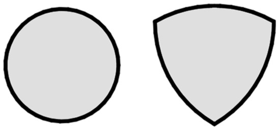
Figure 1.
A comparison of cross-sections: on the left, a circular section; on the right, a Reuleaux triangle section. Both shapes have the same reference area.
The increase in perimeter-to-area ratio (P/A), characteristic of the Reuleaux triangle section (the internal section and external view of the VRA device are shown in Figure 2), is theoretically expected to enhance the density and uniformity of cavitational microbubble nucleation sites, thus improving overall cavitation process efficiency [4,19,20]. This prediction is supported by literature indicating that increased wall surface area and more-complex internal geometries are crucial factors for nucleation and intensification of cavitation [1,2,19]. However, the specific effect associated with using the Reuleaux triangle section remains a theoretical hypothesis requiring further experimental confirmation.
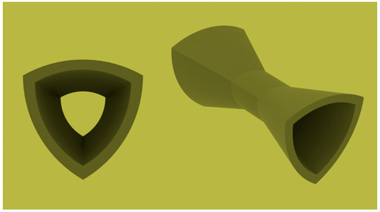
Figure 2.
Internal cross-section and external view of VRA device.
To further enhance cavitation intensity, the use of helical variants is hypothesized, involving axial twisting of the triangular conduit section. The Reuleaux triangle was chosen specifically for its constant width, allowing axial twisting without altering the internal channel profile. This feature enables controlled and uniform flow rotation (swirl), a fundamental condition for developing VRAt configurations [21].
In contrast, other non-circular geometries lacking constant width cannot maintain a regular internal section during axial twisting, limiting the possibility of generating uniform swirl. This configuration induces rotational flow, adding a centrifugal component that theoretically promotes bubble collapse and thus intensifies cavitation. Studies on swirl phenomena indicate that cavitation generated by helical jets enhances bubble collapse intensity and uniformity, significantly improving efficiency in the degradation of organic pollutants in aqueous solutions [22,23]. The internal structure and external view of a possible VRAt device are shown in Figure 3.
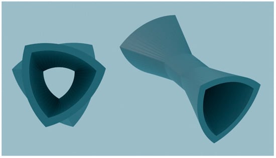
Figure 3.
Internal cross-section and external view of VRAt device.
Two main configurations can be hypothesized for VRAt devices: VRAt-CR (Co-Rotating): Flow rotates in the same direction in both convergent and divergent zones; VRAt-RR (Reverse Rotation): The rotation direction is reversed in the divergent zone, theoretically creating localized pressure gradients of higher intensity.
The proposed analysis focuses on a theoretical comparison among VRA, VRAt-CR, and VRAt-RR configurations, utilizing a scalable mathematical formulation of fundamental cavitation collapse parameters, such as implosion velocity, collapse time, energy, and shock pressure. A deeper understanding of these dynamics could decisively contribute to designing more efficient, selective, and sustainable cavitation devices, with applications ranging from water treatment and nutraceutical valorization to non-thermal processing of sensitive matrices like milk, juices, and craft beers [24,25,26].
2. The Role of the Perimeter-to-Area Ratio (P/A) in the Design of Cavitating Devices
To assess the influence of geometry on cavitation performance, a comparison of the perimeter-to-area ratio (P/A) between two configurations—a circular throat and Reuleaux triangle throat—is proposed. This comparison can provide insight into potential differences in the distribution of nucleation sites and overall cavitation performance [4,19,20].
For a circular throat with radius ,
For a Reuleaux triangle throat with side length ,
Each of the three cusps of the Reuleaux triangle features an internal angle of 120°. Due to the presence of pronounced cusps, this shape has a significantly greater perimeter compared to a circular section of equal area, resulting in a substantial increase in the perimeter-to-area ratio (P/A). This particular configuration, characterized by sharply defined cusps, leads to a markedly higher perimeter than that of an equivalent-area circular section, thereby generating a notable increase in the P/A ratio. As a result, the density and uniformity of cavitation microbubble nucleation sites are enhanced, significantly improving the efficiency of the process [19,20].
Moreover, several theoretical studies have shown that the presence of more articulated surfaces and surface-bound nuclei promotes bubble nucleation through diffusion-driven mechanisms [27].
When the areas are equal , this yields
Substituting this expression into the formula for , one can directly compare the two configurations. The ratio of pressure losses (proportional to P/A) is therefore
From a physical standpoint, the circle represents the shape that, for a given area, has the minimum perimeter. In contrast, the Reuleaux triangle, while maintaining the same area, features cusps that extend the boundary of the section. This geometric characteristic allows for more effective use of the wall as a “catalyst” for bubble nucleation: the longer the perimeter, the greater the number of cavitation events and the more uniform their distribution.
In general, optimizing the P/A ratio can serve as a key design strategy in Venturi devices, as it may help increase the intensity of cavitation collapse while improving its localization and selectivity. The use of innovative geometries such as the Reuleaux triangle would thus enable the development of higher-performance systems for food, extraction, and environmental processes, reducing energy consumption and enhancing overall operational sustainability [21].
Attention to the P/A ratio also lays the groundwork for introducing more advanced geometric configurations. In particular, the integration of rotational elements (swirl) in VRAt-type devices opens up even more promising scenarios, where pressure modulation and the distribution of cavitation effects can be controlled with greater precision by leveraging both geometry and flow dynamics.
Moreover, several studies have shown that the presence of swirl, as well as microstructuring of internal surfaces, can enhance microbial disruption and increase the selectivity of cell disruption processes [28].
3. Cavitation Regimes and Implosion Modeling in Swirling and Axial Venturi Flows
This section investigates the influence of internal geometry and the potential presence of swirl on the distribution, intensity, and localization of cavitation collapse within Venturi devices. In axial-flow configurations, such as the VRA, the fluid stream develops along the axis without centrifugal contributions. Under these conditions, cavitation is initiated and evolves symmetrically, governed exclusively by the pressure gradient induced by the converging–diverging geometry, as illustrated in Figure 4, where the streamlines remain linear and parallel to the conduit axis [3,4].
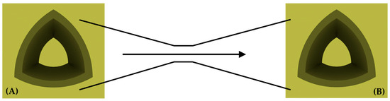
Figure 4.
Flow in VRA configuration; axial, non-rotating flow without centrifugal effects. (A) Converging section; (B) Diverging section.
Introducing swirl, meaning a rotational component in the flow, in twisted configurations such as VRAt adds a centrifugal effect that changes the internal pressure field and helps localize the cavitation collapse [21,29]. This effect can be expressed as
where is the average tangential velocity, is the fluid density, and is the equivalent radius of the section under consideration. The modified pressure available for cavitation collapse, indicated as Δ, is therefore the sum of the pressure drop due to the Venturi geometry (Δ) and the centrifugal contribution :
In the VRAt-CR (Co-Rotating) configuration, the swirl field remains uniform throughout the entire duct, including both the converging and diverging sections. This uniform distribution of flow rotation contributes to a more stable cavitation field, making the device suitable for the distributed and continuous treatment of the entire liquid matrix, due to the increase in Δ compared to the non-swirling configuration [30]. Figure 5 illustrates the flow structure for this configuration, highlighting the consistent direction of rotational motion in both main sections.
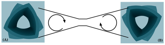
Figure 5.
Flow in VRAt-CR configuration. Uniform clockwise swirl throughout converging and diverging sections. (A) Converging section; (B) Diverging section.
In contrast, in the VRAt-RR (Reverse Rotation) configuration, the swirl direction reverses between the converging and diverging sections. In this case, the centrifugal contribution is evaluated separately for the two regions:
and the effective pressure drop driving cavitation is
This swirl reversal induces a strong local pressure gradient and a peak in cavitation intensity within the transition region, as illustrated in Figure 6. The opposing swirl directions between the converging and diverging sections promote the formation of a localized collapse. This behavior may be advantageous for selective treatments and for maximizing mechanical energy delivery in targeted regions [21,29].
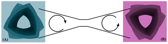
Figure 6.
Flow in VRAt-RR configuration. Swirl inversion between converging and diverging regions. (A) Converging section; (B) Diverging section.
Simulations and theoretical models demonstrate that these geometric and dynamic variations enable precise modulation of the cavitation field distribution. The VRAt-CR configuration tends to generate continuous and spatially distributed effects, while the VRAt-RR configuration concentrates the implosion within a narrow region of the duct. This level of control is crucial in industrial applications where either uniform treatment, such as in emulsification or compound extraction, or targeted effects, such as in cell lysis or localized microbial inactivation, are required.
The proposed theoretical framework, built on generalizable physical parameters that can be easily adapted to different scales and geometries, offers a valuable basis for the design of new devices and supports future experimental development without relying on calibration from specific operating conditions.
Implosion Performance: Introduction and Overview
This section analyzes how different Venturi tube geometries may influence the energy released during cavitation bubble collapse, thereby defining the implosion performance of each device. The key parameters that determine the effectiveness of the phenomenon are as follows:
Collapse time : The time required for a cavitation bubble to completely contract;
- Implosion velocity : The average speed at which the bubble surface moves toward the center;
- Shock pressure : The peak pressure generated by the implosion;
- Collapse energy : The mechanical energy released per unit volume.
A comparative evaluation of the different Venturi device configurations (circular, VRA, VRAt-CR, VRAt-RR) was performed based on theoretical parameters estimated through the analytical relationships developed in this study, with particular focus on the role of the perimeter-to-area ratio and the centrifugal contribution Φ (Equations (4)–(22)) [29,30,31].
The resulting values are summarized in Table 1.

Table 1.
Predicted theoretical parameters for various Venturi configurations, expressed as relative ratios with respect to baseline circular device (baseline = 1).
Four Venturi device configurations are compared:
- Circular Venturi (baseline case, normalized to 100%);
- Reuleaux Venturi (VRA), with a pressure drop ;
- VRAt-CR (Co-Rotating), introducing a uniform centrifugal contribution;
- VRAt-RR (Reverse Rotation), presenting a change in swirl direction between the converging and diverging sections.
The fundamental physical quantities governing bubble collapse dynamics are expressed by the following equations:
Collapse Time:
Expression (12) indicates that an increase in the pressure available for collapse (Δp) results in a shorter bubble implosion time.
Although no specific experimental or energy data are currently available, the theoretical reduction in collapse time predicted by the model suggests that the overall treatment duration may also decrease proportionally, assuming constant power input. This would imply lower energy consumption per unit volume processed, thereby improving the energy efficiency ratio (kWh/m3).
The model specifically predicts that the collapse time could decrease from 1 to approximately 0.67 compared to traditional circular devices, corresponding to a preliminary energy savings estimate in the range of 30–35%. These values are indicative and should be verified through dedicated experimental validation.
In VRA devices, the increased perimeter-to-area ratio leads to a pressure drop more than twice that of the circular configuration, resulting in a corresponding decrease in collapse time.
The average implosion velocity is given by
By substituting the value of , the following expression is obtained:
The maximum pressure generated during collapse, according to the cavitation implosion model, is proportional to the square of the implosion velocity:
The energy released per unit volume during collapse can be approximated as
The higher the shock pressure, the greater the energy transmitted to the surrounding medium.
In the circular Venturi device, cavitation is initiated by the narrowing and acceleration of the flow, but the pressure drop is limited due to the low perimeter-to-area ratio.
In the VRA configuration (Figure 4), the higher perimeter-to-area ratio enhances the local pressure gradient, which leads to a significant reduction in collapse time and an increase in both implosion velocity and shock pressure, as described by the previous equations [30,31].
In the VRAt-CR device (Figure 5), this geometric effect is combined with a tangential velocity component , which introduces a centrifugal contribution. The resulting axial pressure gradient, obtained from the projection of the Navier–Stokes equations, is expressed as
where the term represents the pressure drop caused by the rotational motion. This effect leads to a further increase in the local pressure difference, resulting in faster and more intense bubble collapses that occur over a larger volume [29,32].
In the VRAt-RR configuration (Figure 6), the tangential velocity component changes between the converging and diverging sections, creating a centrifugal gradient that is not constant. As a result, the model includes an additional term that accounts for this spatial variation:
The rapid variation in the rotational field may induce highly localized and intense collapses, which are ideal for selective applications such as microbial inactivation and cell disruption.
In conventional and Reuleaux Venturi devices (VRA), the axial vorticity is zero , whereas in twisted configurations (VRAt), the imposed swirl generates an axial vorticity that can be calculated as
This makes it possible to control both the intensity and the localization of cavitation. In addition, the device design allows the internal twist to be adjusted, making it possible to tune the swirl intensity according to the properties of the processed matrix. Each application may require specific cavitation conditions to achieve optimal performance [30,31].
In rotational Venturi devices (VRAt), the presence of swirl introduces a centrifugal term that helps reduce the static pressure in the flow core. This term can be expressed as
- ρ is the fluid density [kg/m3];
- is the local tangential velocity [m/s];
- is the radial distance from the axis [m].
The cavitation condition can therefore be expressed as
and in non-dimensional form
Here, is the modified cavitation number, which accounts for both the geometric pressure drop and the centrifugal contribution induced by swirl. Lower values indicate a higher tendency for cavitation, making a useful parameter for comparing different configurations under varying flow conditions.
From a design perspective, supports the optimization of geometry and operating conditions according to specific application requirements.
In devices without swirl, the centrifugal term is zero. In VRAt configurations, instead, the rotational component of the flow allows the pressure to drop more easily below the cavitation threshold. The actual effect of this contribution depends on the swirl distribution and device geometry, and should be evaluated experimentally [29,32].
Across all configurations, the analysis demonstrates that geometric control and flow modulation can be used to optimize both cavitation selectivity and efficiency. This is achieved by leveraging the direct relationship between pressure drop, implosion velocity, and shock pressure. Given the purely theoretical and generalizable nature of the proposed model, the results are directly applicable to future CFD studies and experimental validations [32].
4. Shear Layer Dynamics and Cavitation Collapse Control
In cavitating devices with swirl (VRAt), the dynamics of internal shear layers are critical for controlling both the location and intensity of cavitation bubble collapse. These layers form in regions with strong tangential velocity gradients—where the velocity component changes rapidly in space. Hydrodynamic instabilities, particularly those of the Kelvin–Helmholtz type, may develop along these layers, promoting cavitation onset and intensifying the collapse [33,34].
Beyond shear instabilities, the dynamics of cavitation bubble collapse near solid boundaries are strongly influenced by wall effects, often resulting in the formation of high-velocity microjets directed toward the surface—a phenomenon known as the Bjerknes effect [35].
Recent research has demonstrated that both the primary and secondary Bjerknes forces are significantly affected by bubble translation, pulsation, and deformation, as well as by the amplitude and frequency of the applied acoustic field [36,37]. In particular, the presence of multiple bubbles and their mutual interactions give rise to attractive or repulsive forces, promoting bubble clustering and microbubble self-organization. These collective effects locally modify energy distribution and collapse dynamics [36,37,38].
While such mechanisms can intensify mechanical stresses and increase the risk of surface erosion, they can also be harnessed to enhance targeted applications, including sonochemical reactions and the selective disruption of structured materials.
Recent theoretical developments and experimental observations have highlighted the need to refine the classical formulation of Bjerknes forces. In particular, additional contributions arising from relative motion, bubble deformation, and nonlinear acoustic conditions must be accounted for to achieve more accurate predictions of cavitation phenomena in advanced reactor systems.
In the Co-Rotating (CR) configuration, the swirl field remains continuous along the axis, and the shear layer is stable and symmetric. This promotes a more uniform and distributed cavitation collapse. In contrast, the Reverse Rotation (RR) configuration introduces an abrupt change in swirl direction, generating strong radial and axial gradients. These create narrow regions of high instability, where bubble collapse becomes significantly more localized and intense.
The energy released by the collapse of a single bubble can be estimated as
- is the collapse energy per bubble [J];
- is the maximum bubble radius before collapse [m];
- is the vapor pressure [Pa];
- is the local minimum pressure in the core [Pa].
In RR devices, is lower than in CR configurations, resulting in more energetic and concentrated collapses.
The three-dimensional structure of the shear layer can be characterized by the gradient of the tangential velocity:
where is the radial coordinate, the angular coordinate, the axial coordinate, and the tangential velocity component.
Elevated values of identify regions of high instability and increased likelihood of effective cavitation [33,34]. This parameter is instrumental in locating the most active zones within the flow and guiding the optimization of internal device geometry. By modulating shear layers, it becomes possible to localize cavitation collapse and induce selective mechanical effects—useful in processes such as structural disruption, compound release, and dispersion refinement.
Notably, a spatially controlled distribution of can maximize the local release of collapse energy (), thereby improving treatment efficiency in targeted regions while minimizing unintended effects on the surrounding matrix [33,34,35,36,37,38].
5. Conclusions
The theoretical analysis highlights the crucial role of internal geometry and flow field in determining both the efficiency and spatial localization of cavitation within Venturi devices. In fixed-geometry configurations, such as those based on a Reuleaux triangle cross-section (VRA), axial pressure distribution correlates directly with variations in channel geometry, following the classical Venturi effect. This approach enables cavitation behavior to be predicted solely from geometric features and initial operating conditions.
In VRAt devices, the introduction of a swirl component generates a centrifugal contribution (Φ), which, when combined with the geometric effect, significantly alters the pressure distribution and shifts the minimum pressure point. This enables modulation of both the localization and intensity of cavitation collapse—even in systems with constant axial geometry—allowing the phenomenon to be tailored to specific process requirements. Additionally, the ability to adjust the internal twist in VRAt devices provides greater design flexibility, supporting the optimization of cavitation conditions based on the physical and chemical properties of the target matrix.
The proposed model suggests that such hydrodynamic control can shorten collapse time and increase implosion velocity, resulting in a more intense and localized energy release. Importantly, this intensification is achieved without modifying the geometry, but rather by tuning flow parameters alone. These improvements could translate into enhanced process efficiency, reduced treatment times, and potentially lower energy consumption—making these devices particularly attractive for large-scale industrial applications.
Although direct experimental data are not yet available, the model indicates that the reduced collapse time in VRA devices could yield energy savings in the range of 30–35% compared to conventional circular geometries, due to more than double the pressure drop. These estimates are preliminary and will require confirmation through future experimental studies.
The use of dimensionless parameters such as Φ, axial vorticity , shear layer intensity , and the modified cavitation number enables the design of cavitating devices that are scalable, selective, and efficient. From an industrial standpoint, this opens the door to integrating VRA and VRAt devices into existing process lines, offering increased operational flexibility, precise control, and potentially enhanced energy efficiency.
In particular, VRAt configurations—due to their ability to concentrate cavitation collapse within small, high-intensity volumes—are especially well suited to selective treatments such as structural disruption, compound extraction, and microbial inactivation. Applications widely reported in the literature and demonstrated in pilot-scale systems—such as gluten reduction and prenylflavonoid enrichment in beer via controlled cavitation—underscore the potential of these strategies for more sustainable, efficient, and quality-preserving processes.
Comparisons with other non-circular geometries and alternative intensification strategies have thus far been limited to theoretical or analytical studies. Quantitative evaluations based on experimental or numerical data remain a key objective for future research.
Finally, it should be emphasized that this work is entirely theoretical, and all estimates regarding efficiency and operational potential must be validated through dedicated experimental studies and simulations using real matrices under industrial conditions. In this context, the implementation of advanced numerical simulations (e.g., CFD, VOF) is strongly recommended to further investigate and confirm the findings. Future efforts should focus on experimentally validating the proposed models and optimizing flow parameters according to actual process requirements.
Funding
This research received no external funding.
Institutional Review Board Statement
Not applicable.
Informed Consent Statement
Not applicable.
Data Availability Statement
The original contributions presented in this study are included in the article. Further inquiries can be directed to the corresponding author.
Conflicts of Interest
The author declares no conflicts of interest.
Abbreviations
The following abbreviations are used in this manuscript:
| VRA | Venturi Reuleaux Albanese |
| VRAt | Venturi Reuleaux Albanese twist |
| VRAt-CR | Venturi Reuleaux Albanese twist (Co-Rotating) |
| VRAt-RR | Venturi Reuleaux Albanese twist (Reverse Rotation) |
References
- Arya, S.S.; More, P.R.; Ladole, M.R.; Pegu, K.; Pandit, A.B. Non-thermal, energy efficient hydrodynamic cavitation for food processing, process intensification and extraction of natural bioactives: A review. Ultrason. Sonochem. 2023, 98, 106504. [Google Scholar] [CrossRef]
- Panda, D.; Saharan, V.K.; Manickam, S. Controlled Hydrodynamic Cavitation: A Review of Recent Advances and Perspectives for Greener Processing. Processes 2020, 8, 220. [Google Scholar] [CrossRef]
- Carpenter, J.; Badve, M.; Rajoriya, S.; Pandit, A.B. Hydrodynamic cavitation: An emerging technology for the intensification of various chemical and physical processes in a chemical process industry. Rev. Chem. Eng. 2017, 33, 433–468. [Google Scholar] [CrossRef]
- Bashir, T.A.; Soni, A.G.; Mahulkar, A.V.; Pandit, A.B. The CFD Driven Optimization of a Modified Venturi for Cavitation Activity. Can. J. Chem. Eng. 2011, 89, 1366–1375. [Google Scholar] [CrossRef]
- Brennen, C.E. Cavitation and Bubble Dynamics; Oxford University Press: Oxford, UK, 1995. [Google Scholar] [CrossRef]
- Franc, J.P.; Michel, J.M. Fundamentals of Cavitation; Kluwer Academic Publishers: Dordrecht, The Netherlands, 2004. [Google Scholar] [CrossRef]
- Wu, Z.; Ferreira, D.F.; Crudo, D.; Bosco, V.; Stevanato, L.; Costale, A.; Cravotto, G. Plant and biomass extraction and valorisation under hydrodynamic cavitation. Processes 2019, 7, 965. [Google Scholar] [CrossRef]
- Garcia Bustos, K.A.; Rossetti, C.; Frascarelli, D.; Brunori, G. Hydrodynamic cavitation as a promising technology for fresh produce-based beverages processing. Innov. Food Sci. Emerg. Technol. 2024, 96, 103784. [Google Scholar] [CrossRef]
- Ciriminna, R.; Albanese, L.; Di Stefano, V.; Delisi, R.; Avellone, G.; Meneguzzo, F.; Pagliaro, M. Beer produced via hydrodynamic cavitation retains higher amounts of xanthohumol and other hops prenylflavonoids. LWT-Food Sci. Technol. 2018, 91, 160–167. [Google Scholar] [CrossRef]
- Albanese, L.; Ciriminna, R.; Meneguzzo, F.; Pagliaro, M. Beer-brewing powered by controlled hydrodynamic cavitation: Theory and real-scale experiments. J. Clean. Prod. 2017, 142, 1457–1470. [Google Scholar] [CrossRef]
- Albanese, L.; Ciriminna, R.; Meneguzzo, F.; Pagliaro, M. Gluten reduction in beer by hydrodynamic cavitation assisted brewing of barley malts. LWT-Food Sci. Technol. 2017, 82, 342–353. [Google Scholar] [CrossRef]
- Simões, A.M.A. Application of Hydrodynamic Cavitation in Brewing: Impacts on Gluten Levels and Process Efficiency. Master’s Thesis, Universidade do Minho, Braga, Portugal, 2022. [Google Scholar]
- Manoharan, D.; Zhao, J.; Ranade, V.V. Cavitation technologies for extraction of high value ingredients from renewable biomass. TrAC Trends Anal. Chem. 2024, 174, 117682. [Google Scholar] [CrossRef]
- Zhu, X.; Caihe, P.; Kang, W.; Zhang, J.; Yin, R.; Wu, Z.; Dong, Z. Cavitation behavior in a coaxial ultrasonic microreactor and its effects on mixing performance and liposomes preparation. Chem. Eng. Process. Process Intensif. 2025, 209, 110155. [Google Scholar] [CrossRef]
- Wu, P.; Bai, L.; Lin, W.; Wang, X. Mechanism and dynamics of hydrodynamic-acoustic cavitation (HAC). Ultrason. Sonochem. 2018, 49, 89–96. [Google Scholar] [CrossRef]
- Liu, L.; Zhao, S.; Yao, C.; Chen, G. A novel approach to intensify fluid mixing by introducing a “pre-cavitation” stage in an ultrasonic microreactor. AIChE J. 2025, 71, e18810. [Google Scholar] [CrossRef]
- Tang, J.; Zhu, X.; Jambrak, A.R.; Sun, D.W.; Tiwari, B.K. Mechanistic and synergistic aspects of ultrasonics and hydrodynamic cavitation for food processing. Crit. Rev. Food Sci. Nutr. 2024, 64, 8587–8608. [Google Scholar] [CrossRef]
- Yuan, M.; Kang, Y.; Shi, H.; Li, D.; Li, H. Experimental Investigation on the Characteristic of Hydrodynamic-Acoustic Cavitation (HAC). J. Mar. Sci. Eng. 2022, 10, 309. [Google Scholar] [CrossRef]
- Kanthale, P.M.; Gogate, P.R.; Pandit, A.B.; Wilhelm, A.M. Dynamics of cavitational bubbles and design of a hydrodynamic cavitational reactor: Cluster approach. Ultrason. Sonochem. 2005, 12, 441–452. [Google Scholar] [CrossRef]
- Li, M.; Bussonnière, A.; Bronson, M.; Xu, Z.; Liu, Q. Study of Venturi tube geometry on the hydrodynamic cavitation for the generation of microbubbles. Miner. Eng. 2019, 132, 268–274. [Google Scholar] [CrossRef]
- Zhang, X.; Lin, R.; Zhang, L.; Chen, J.; Li, M.; Wang, Y. Numerical investigation of effect of geometric parameters on performance of rotational hydrodynamic cavitation reactor. Ultrason. Sonochem. 2024, 103, 106790. [Google Scholar] [CrossRef]
- Wang, J.; Guo, Y.; Guo, P.; Yu, J.; Guo, W.; Wang, X. Degradation of reactive brilliant red K-2BP in water using a combination of swirling jet-induced cavitation and Fenton process. Sep. Purif. Technol. 2014, 130, 1–6. [Google Scholar] [CrossRef]
- Wang, J.; Wang, X.; Guo, P.; Yu, J. Degradation of Reactive Brilliant Red K-2BP in Aqueous Solution Using Swirling Jet-Induced Cavitation Combined with H2O2. Ultrason. Sonochem. 2011, 18, 494–500. [Google Scholar] [CrossRef]
- Sun, X.; Xuan, X.; Ji, L.; Chen, S.; Liu, J.; Zhao, S.; Park, S.; Yoon, J.Y.; Om, A.S. A novel continuous hydrodynamic cavitation technology for the inactivation of pathogens in milk. Ultrason. Sonochem. 2021, 71, 105382. [Google Scholar] [CrossRef]
- Pathania, S.; Ho, Q.T.; Hogan, S.A.; McCarthy, N.; Tobin, J.T.; Gogate, P.R. Applications of Hydrodynamic Cavitation for Instant Rehydration of High Protein Milk Powders. J. Food Eng. 2018, 225, 18–25. [Google Scholar] [CrossRef]
- Ciriminna, R.; Scurria, A.; Pagliaro, M. Natural Product Extraction via Hydrodynamic Cavitation. Sustain. Chem. Pharm. 2023, 33, 101083. [Google Scholar] [CrossRef]
- Groß, T.F.; Pelz, P.F. Diffusion-driven nucleation from surface nuclei in hydrodynamic cavitation. J. Fluid Mech. 2017, 830, 138–164. [Google Scholar] [CrossRef]
- Balasundaram, B.; Harrison, S.T.L. Disruption of Brewers’ yeast by hydrodynamic cavitation: Process variables and their influence on selective release. Biotechnol. Bioeng. 2006, 94, 303–311. [Google Scholar] [CrossRef]
- Simpson, A.; Ranade, V.V. Flow characteristics of vortex based cavitation devices. AIChE J. 2019, 65, e16675. [Google Scholar] [CrossRef]
- Simpson, A.; Ranade, V.V. Modeling hydrodynamic cavitation in venturi: Influence of venturi configuration on inception and extent of cavitation. AIChE J. 2019, 65, 421–433. [Google Scholar] [CrossRef]
- Wang, T.; Wang, P.; Zhang, K.; Yang, F.; Huang, Y.; Huang, C. Lumped kinetic model for degradation of chitosan by hydrodynamic cavitation. Arab. J. Chem. 2021, 14, 102939. [Google Scholar] [CrossRef]
- Zeman, R.; Rudolf, P. Optimizing Venturi Nozzle Design for Enhanced Cavitation and Pressure Dynamics: A Comparative Analysis of Turbulence Models for Cavitating Flow Characterization. Eng. Mech. 2024, 30, 326–329. [Google Scholar] [CrossRef]
- Podbevšek, D.; Petkovšek, M.; Ohl, C.D.; Dular, M. Kelvin-Helmholtz instability governs the cavitation cloud shedding in Venturi microchannel. Int. J. Multiph. Flow 2021, 142, 103700. [Google Scholar] [CrossRef]
- Gwala, K.; Pathan, T.A.; Pensia, R.K.; Mansuri, S.; Dashora, H. Polarization and coriolis forces impact on the Kelvin-Helmholtz instability of viscous dusty plasma. Chin. J. Phys. 2024, 90, 572–579. [Google Scholar] [CrossRef]
- Kokhuis, T.J.A.; Garbin, V.; Kooiman, K.; Naaijkens, B.A.; Juffermans, L.J.M.; Kamp, O.; van der Steen, A.F.W.; Versluis, M.; de Jong, N. Secondary Bjerknes Forces Deform Targeted Microbubbles. Ultrasound Med. Biol. 2013, 39, 490–506. [Google Scholar] [CrossRef]
- Zhang, X.; Li, F.; Wang, C.; Mo, R.; Hu, J.; Guo, J.; Lin, S. Effects of translational motion on the Bjerknes forces of bubbles activated by strong acoustic waves. Ultrasonics 2022, 126, 106809. [Google Scholar] [CrossRef]
- Liu, J.; Wang, X.; Liang, J.; Qiao, Y. Refined secondary Bjerknes force equation for double bubbles with pulsation, translation, and deformation. Ultrason. Sonochem. 2024, 102, 106756. [Google Scholar] [CrossRef]
- Wang, X.J.; Ning, Z.; Lv, M.; Yao, J.; Sun, C. The Secondary Bjerknes Force between Two Bubbles in Ultrasonic Field. J. Phys. Soc. Jpn. 2022, 91, 014401. [Google Scholar] [CrossRef]
Disclaimer/Publisher’s Note: The statements, opinions and data contained in all publications are solely those of the individual author(s) and contributor(s) and not of MDPI and/or the editor(s). MDPI and/or the editor(s) disclaim responsibility for any injury to people or property resulting from any ideas, methods, instructions or products referred to in the content. |
© 2025 by the author. Licensee MDPI, Basel, Switzerland. This article is an open access article distributed under the terms and conditions of the Creative Commons Attribution (CC BY) license (https://creativecommons.org/licenses/by/4.0/).