Article

Advances in Illumination of Lengthy Road Tunnels by Means of Innovative Vaulting and Sustainable Control of Flicker Perturbations

by
Joseph Cabeza-Lainez
1,* and
Antonio Peña-García
2
1
Department Architectural Composition, University of Sevilla, 41012 Sevilla, Spain
2
Department Civil Engineering, University of Granada, 18071 Granada, Spain
*
Author to whom correspondence should be addressed.
Sustainability 2025, 17(15), 6680; https://doi.org/10.3390/su17156680
Submission received: 11 June 2025 / Revised: 15 July 2025 / Accepted: 18 July 2025 / Published: 22 July 2025

Abstract

Traditional approaches in tunnel lighting have been directed toward the installation of appropriate luminaires in the intermediate and transitional sections with the simple objective of diminishing the effect of delayed visual accommodation during daylight hours. Such efforts run in parallel with the target of keeping the huge electrical use at the lowest level. Nevertheless, inadequate attention has been conceded to the interior areas, whose noticeable longitude in several instances, and subsequently the duration of occupancy of the users, can produce discomfort in the majority of the tunnel or underground passageway. It is in this region where the flicker effect presents a more remarkable impact. Although such effect is in fact uncomfortable, the strategies to eliminate it efficiently have not been developed in depth and the result is still deserving, especially in terms of sustainability. The reasons for this neglect, as well as some particularities and solutions, are exposed and discussed in the present article. Specifically, it is proved that the use of sunlight can be an adequate initiative and a positive energy input into design and retrofit tunnels capable of hampering or totally avoiding such unwanted effect. The innovative tunnel geometry explained in this manuscript is not cylindrical, and it is not based in revolution forms. Thus, it prevents the appearance of such unnerving visual effects, which compromise sustainability and endanger security. We are in the position to explain how the vector field generated by the normal to the points of the novel surface displayed remains non-parallel, ensuring appropriate diffusivity and, consequently, an even distribution of radiated energy. In the same manner, the notion of the tunnel is extended from a linear system to a veritable network of galleries, which can traverse in space bi- or even three-dimensionally. Accordingly, we will offer diverse instances of junctions and splices that further enhance the permeability into the terrain, augmenting the resilience capabilities of this disruptive technology. With all the former, a net reduction of costs reaching 25% can be easily expected with revenues.

1. Introduction

The lighting of road tunnels is a complex task due to its critical impact on drivers and safety [1,2,3,4], as well as its high consumption in economical, energy, and financial resources. This fact is becoming more and more important in recent years due to the exponential increase of tunnel construction, especially the very long ones. As a consequence of the high amounts of energy and raw materials required, as well as the manufacturing processes, the environmental impact of these installations is also high in emissions and other kinds of waste and generally negative for the cause of sustainability.
The explanation to the abovementioned impacts lies in physical, physiological, and psychological peculiarities of human beings. The consequence is that accurate visual perception, good performance, and short visual reaction time (VRT) must be ensured through very high luminance levels, especially during daytime because, otherwise, the slow visual adaptation when passing from bright to darker environments (Figure 1) may cause disturbing effects, making driving even more dangerous [5]. Furthermore, the visual adaptation is not an isolated problem because drivers in tunnels and long underground roads also experience physiological and psychological impairments due to their singular characteristics [6,7,8,9,10,11].
In addition, the excessive luminance levels required to mitigate the abovementioned disturbing effects are a problem in themselves because of the consequent consumption of energy, number of projectors, wiring, and maintenance. All this means a worrying economic and environmental impact. Therefore, an urgent reaction is required, and the design processes for this kind of infrastructure need to be altered. This is the main reason why research on strategies to make tunnel lighting more sustainable through the decrease in the consumption of energy and installed projectors has experienced a big boost in recent years. The proposals to date range from the decrease in the luminance requirements through interventions in the portal surroundings [12] to strategies that introduce the light of the sun inside the tunnel with or without displacement of the infrastructure [13,14]. However, fewer rely on vaulting elements for ensuring a better diffusion of radiated energy, which is overabundant.
In summary, it is necessary to ensure the minimum luminance necessary to achieve visual adaptation and avoid some related disturbing effects that take place during daytime, whilst progressively carrying out a diffuse luminance decrease as the eye gets adapted in order to save energy, installed projectors, and environmental impact.
To implement the decrease, road tunnels are divided into five different sections with different performances of their respective lighting installations. The zones have different lengths and requirements in terms of illuminance from the floor and vertical surfaces. These zones are the following [5]:
Approach area: The section of the unaltered road immediately before the portal gate with a length of the stop distance (SD). The luminance on the driver’s eye in this zone (L20) determines their visual accommodation to the darker environment of the tunnel and, henceforth, the luminance requirements from pavement and walls are much higher than in the following parts inside the tunnel
Threshold zone: The first region of the vault with a length of the braking distance. With the target of ensuring a smooth transition and accurate visual adaptation, such zone presents the highest required luminance (Lth) and, hence, it is the most consuming one in terms of energy and projectors. In spite of its high magnitude, the luminance in this region starts to progressively decay from is second half.
Transition zone: The section of the tunnel immediately connected to the threshold region whose length is that encompassed by a standard car at the maximum permitted speed inside the tunnel for twenty seconds. Its luminous requirements (Ltr) are lower than those of the previous threshold zone. The luminance around this area dwindles progressively due to the necessity of energy savings.
Interior zone: It is the area located after the transition one and lies immediately before the exit zone. Its photometric requirements are the lowest because the driver is supposed to attain a reasonable visual accommodation here. The levels are uniform along the whole area and, depending on the type of tunnel and the traffic density, they can vary between Lin = 1 and 10 cd/m2.
Exit zone: This region starts immediately after the interior zone previously described at SD and finishes at the end of the tunnel. The required luminance, Lex, raises from Lin up to 5 Lin until 20 m before the exit gate, where the visual environment is dominated by the exterior conditions.
According to this division, the interior zone requires the minimum consumption in energy and installed projectors in the full length of the tunnel. Although this circumstance is positive, there are also important cons: the long separation between projectors produces inhomogeneous distribution of luminous energy on the road and walls. The reason is that tunnels have a maximum total size, and the light cones hardly overlap in the interior zone.
The parameter taking into account the distribution of the luminance flux on the pavement and walls is the global luminance uniformity (U0). It represents the uniformity of the visual field perceived by the users, and is defined by CIE International Standard S 017/E:2015 [15] as:
U 0 = L m i n L a v ,
where Lmin and Lav are the minimum and average luminance levels on the pavement, and U0 > 0.4 is required by several norms to grant the uniformity of the visual field.
When the total luminous homogeneity is scarce due to an inhomogeneous distribution of the luminous flux on the vertical surfaces and floors, the drivers can experience one disturbing effect, the so-called “flicker effect”, which is the target of this work.

2. The Flicker Effect

Besides the problem of visual accommodation, luminaire or lamp facilities in tunnels and underground passageways must dampen, among other disturbing circumstances, the “flicker effect”, which is the succession of bright and dim stripes on the pavement and walls, as shown in Figure 2 [5,16,17]. They represent the uneven distribution of energy provided by point sources like conventional lamps. When the succession has some concrete frequencies and duration, it can result in a lack of concentration, headache, or dizziness, and may become a serious danger for drivers, as it leads to accidents with casualties and a lack of confidence for the users. This effect is frequent in the interior zone of road tunnels and the so-called very long underground roads (VLURs).
The frequency of appearance of said stripes has been traditionally represented by Equation (2) [5]:
f = v m a x I ,
where vmax represents the higher velocity allowed in the tunnel or underground facility, and I is the normal distance between the centers of the projectors in the zone of the tunnel under consideration.
According to CIE Publication 88: 2004 [5], the effect is insignificant at frequencies lower than 2.5 Hz and higher than 15 Hz. However, when the frequencies go to the interval from 4 to 11 Hz and the exposure of the succession is longer than twenty seconds, it is recommended to carry out radical actions to change the frequencies because the effect can appear.
Although this interval is well established, it is necessary to highlight that measuring the distance I between projectors from center to center, as per Equation (2), may be too conservative in terms of the calculated frequencies, because it assumes that the light cones have no aperture. According to (2), the flux is strictly reduced to a trough directly under the center of the projector. In other words, the formulae applied to calculate the flicker provided by most regulations make it unviable for any kind of overlap of the light subtended angles even if it actually exists.
Anyhow, the reason behind this effect is precisely the lower luminance demands in the interior zone. Due to the increasing cost and relatively low variety of projector models over the years, the installations in interior zones had high spacing between projectors. The merger of such large distancing with the limited height of the tunnel vault does not allow the overlap of the light subtending angles and, subsequently, a succession of bright and dark stripes appears on the walls and mainly on the road surface [18].
The classical action to avert the flicker effect has been the installation of projectors with ample light angles sufficient to reduce the point-source distribution or using a denser array of lamps of lower power to diminish the separation magnitudes. This last action augments the cost of the facilities and their maintenance.
In the next section, some of the ideas proposed to date are presented.

3. Materials and Methods: Several Proposals to Avoid the Flicker Effect in Tunnels and Very Long Underground Roads (VLURs)

Once we assume the drawbacks to attain a proper overlap of the light cones in the interior zone, it is necessary to think of tactics to improve luminance uniformity and, thus, avoid the flicker effect.
The classical solution consisted of the use of more projectors with lower power in the interior zone, instead of fewer of high luminous flux. In this way, there is a chance to overlap the cones. However, the projectors can be still considered a point-light source, and they are rarely conceived to distribute the luminous flux through the surrounding vaults. Besides, an installation with more projectors is more expensive in terms of initial investments, use of raw materials for wiring and other devices, maintenance, and recycling at the end-of-life cycle of both projectors and lamps.
For this reason, other proposals are demanded. Some works have developed ideas from different perspectives [10,18], but the continuous advances in tunnel lighting have made it possible to introduce new products and strategies that, although initially designed for other purposes, can contribute to eliminate the flicker effect in the threshold zone:
(1)
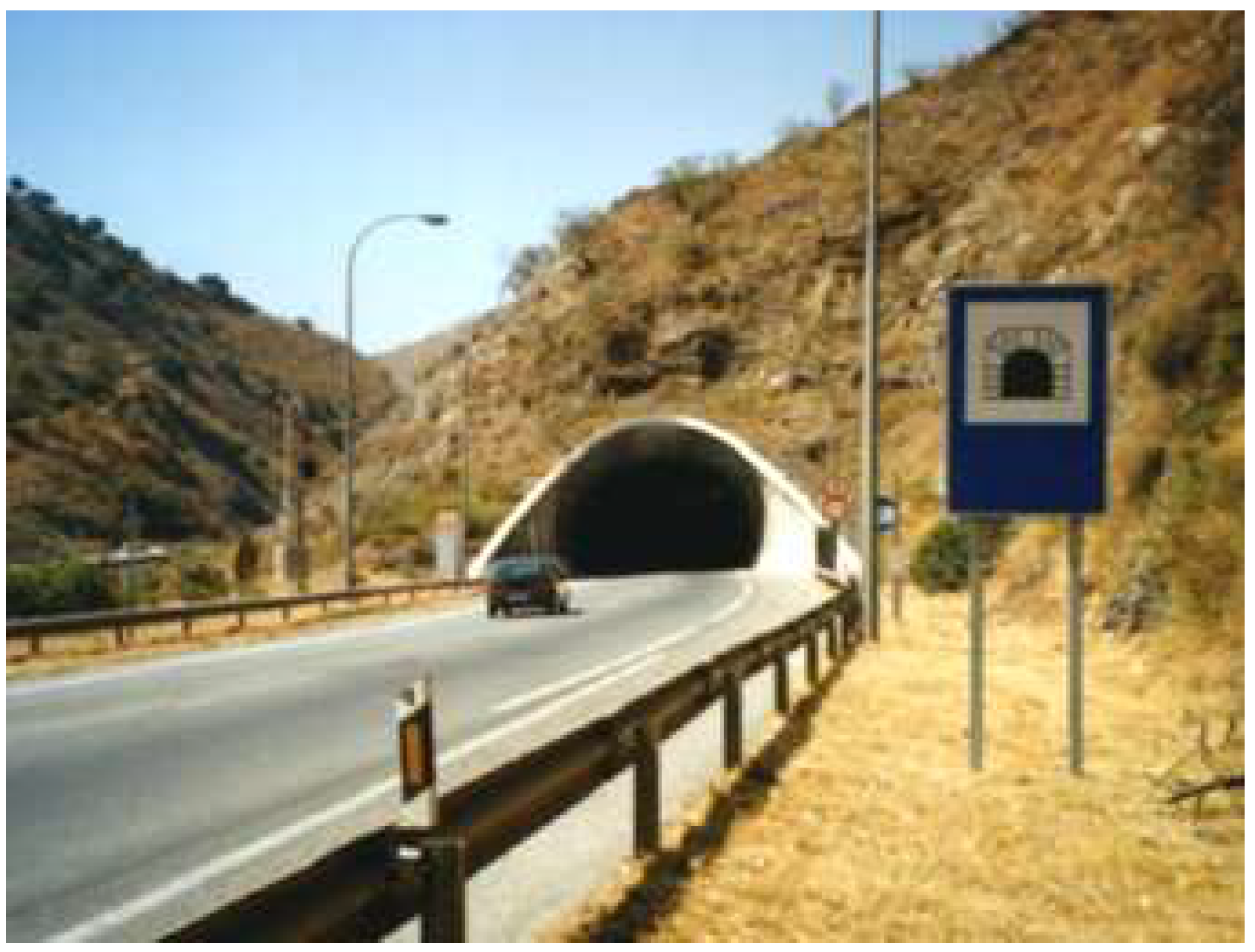
Decrease of the luminance required inside the tunnel through interventions in the portal surroundings, like forestation or introduction of scaled surfaces, to reflect the sunlight out of the L20 cone from the approaching drivers’ eyes. This decrease results in less emitted flux and lower contrasts between light cones and darker areas, contributing to the elimination of the flicker effect.
(2)
Installation of continuous stripes of LED along the whole tunnel or underground road, as shown in Figure 3. These stripes can be placed at least in the interior zone where the flicker effect is more prone to buildup. Although the intensity emitted by these relatively new products is much lower than that emitted by classical high-pressure sodium projectors, the luminance on the road can be enough to fulfill the requests in this zone, even at the nighttime level.
(3)
Supplementing sunlight to the electrical lighting. Although most strategies using sunlight in road tunnels are designed to achieve a good visual adaptation when entering the threshold zone, some of them could be useful in the interior zone to achieve better uniformity.
Among the two kinds of alternatives presented to employ the light of the sun in tunnels, the first one consists of partially displacing the threshold region toward the outside of the tunnel [19,20,21,22,23,24,25,26,27,28,29]. It is evident that this strategy cannot be applied to the interior zone and is not useful to mitigate the flicker effect because, due to the short separation between projectors in this zone, the effect is not likely to happen there.
On the other hand, the second kind of strategy is based on the injection of sunlight within the tunnel through light-pipes with or without heliostats [30,31,32] or through fiber-optics [33,34].
The selection of one or another way to save energy through the use of sunlight depends on many factors and is complex. Some tools recently developed, like the so-called SLT equation [35], have the capability to predict which kind of strategy can be better in each tunnel for the given target energy savings.
Anyhow, the potential use of sunlight to fight the flicker effect is found in the second kind of strategies, that is, the injection of solar flux inside the tunnel to reach the interior region, as long as it is homogeneously distributed on the walls and road surface. In this sense, an injection system was recently presented by Peña-García and Cabeza-Laínez [33]. It consists of a coupled system of “outer light collectors–ground-based light-pipes–distributing vault”, as shown in Figure 4.
This system improves the shortcomings of other proposals thanks to two ground-breaking factors:
-
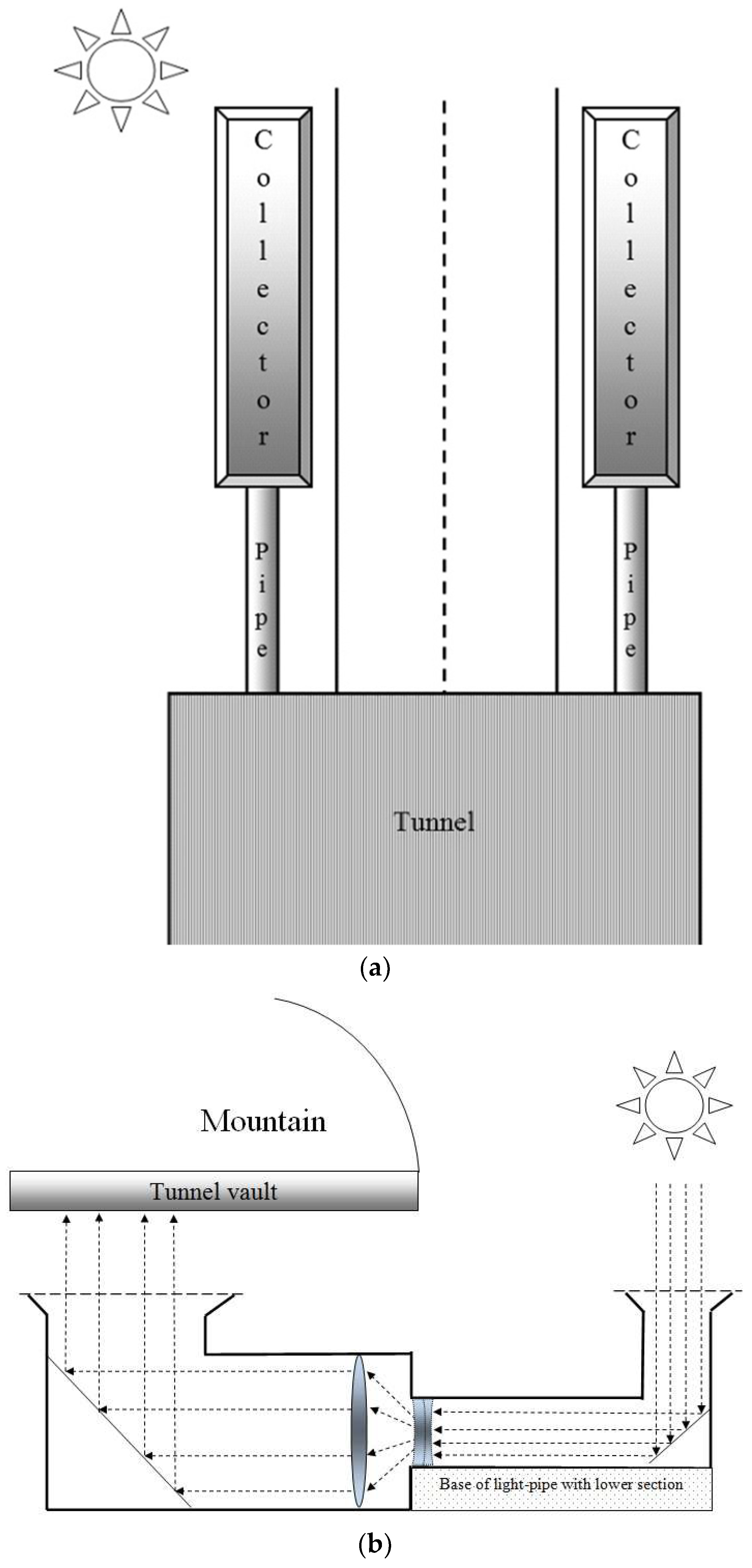
The lower chamber of the light-pipes on the ground and shoulders of the road.
-
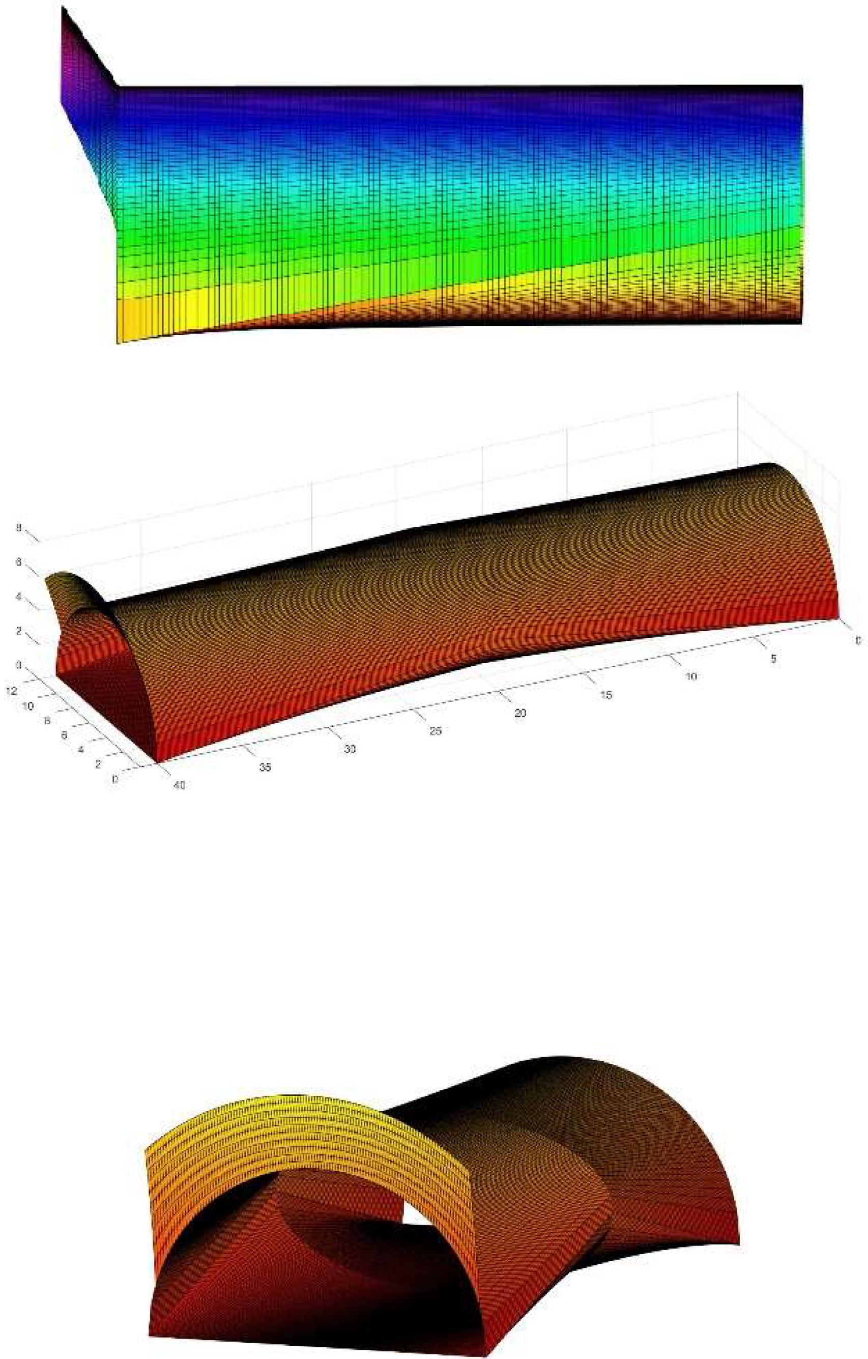
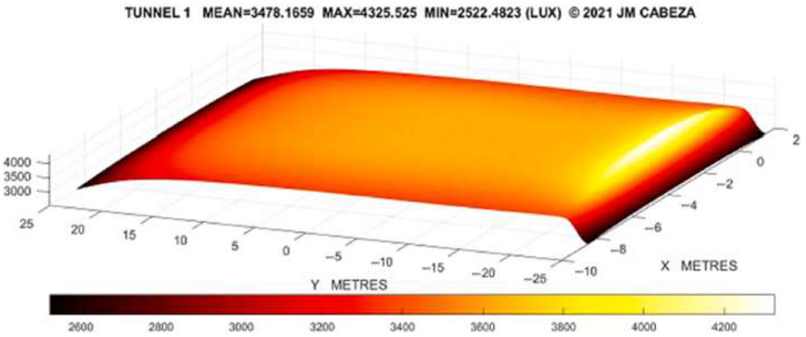
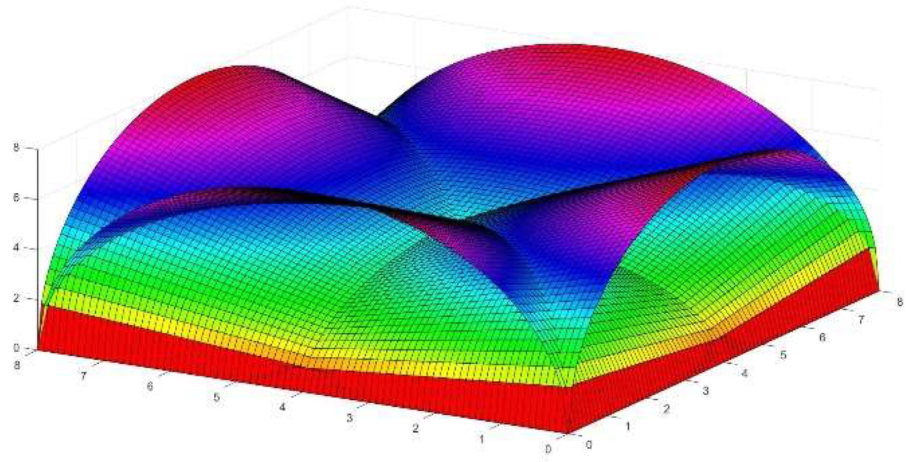
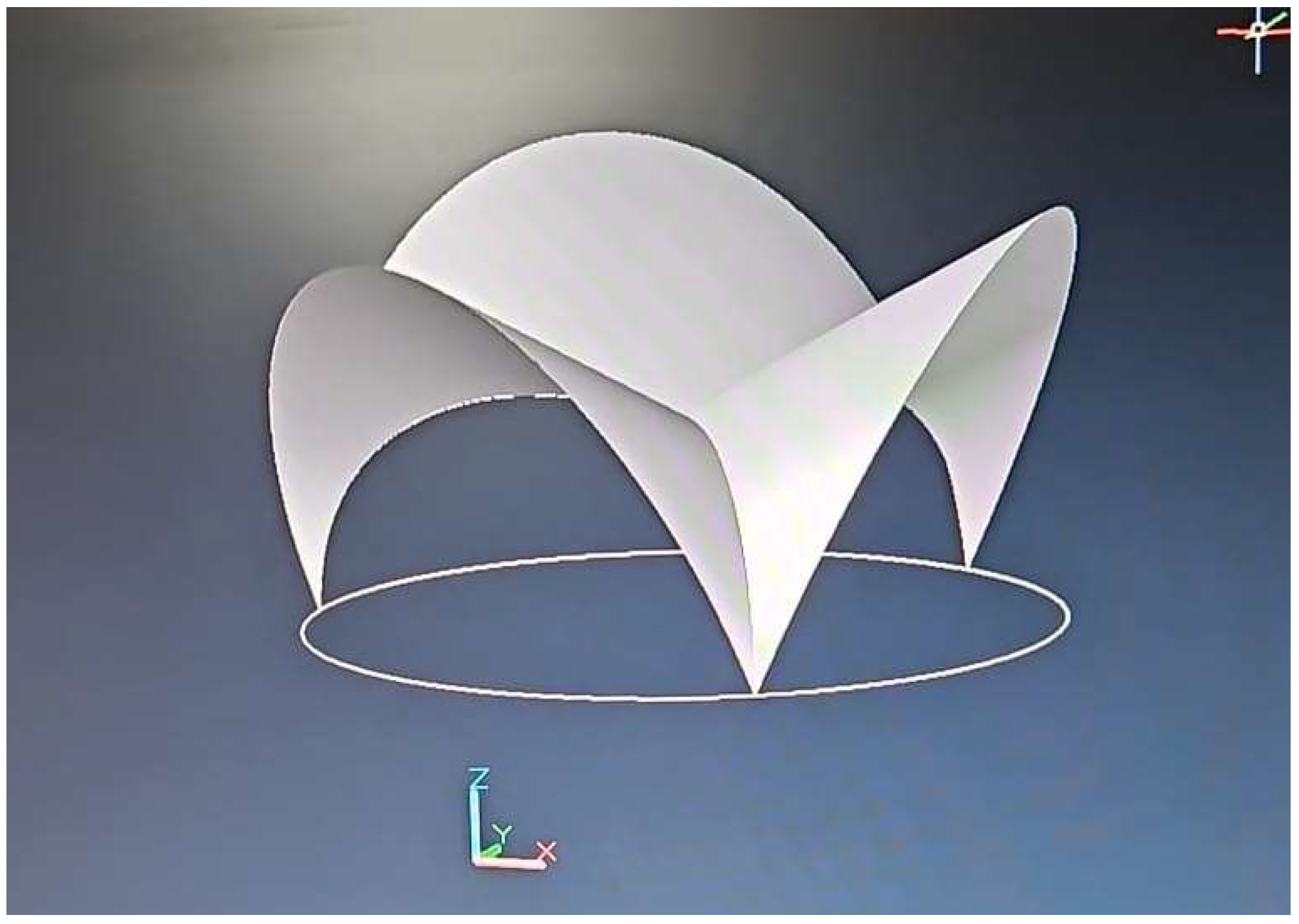
The construction of a complex-shaped vault of camber geometry with sufficient capacity to reflect and diffuse the solar flux transported by the light-pipes homogeneously on the pavement.
To find the internal distribution of solar radiation inside the non-cylindrical geometry that we are proposing, we need to briefly clarify the underlying logic of the novel simulation system that we are about to introduce. It is mainly based on the reciprocity theorem of radiation attributed to Lambert.
Since it was enunciated on several occasions from the 18th century onwards [33], we will simply start with the canonical expression that describes the delivery and incidence of radiated energy among several perfect diffuser elements of any configuration and independently of the position adopted by them, as represented in Figure 5 [34]. The law features just directional cosines, longitudes, and surfaces, that is, dimension magnitudes, according to the equation below (Equation (3)):
d ϕ 12 = E 1 E 2 cos θ 1 cos θ 2 d A 1 d A 2 π r 12 2 .
As previously mentioned, Equation (3) is often termed the reciprocity theorem. It quantifies the probability of incidence of radiative energy E by unit area on any of the elements considered, that is, E1 and E2. The respective entry angles, θ1 and θ2, which are drawn in the graph, represent the tilting to the perpendicular of the vector that unites two differential elements, which belong to the respective surfaces A1 and A2, logically called r12, in the expression as well as in the picture [35,36].
To be able to resolve Expression (3), which permits the evaluation of the magnitude of a so-called form factor (a non-dimensional entity) that reunites in a single value the radiative exchange of the said diffusing surfaces, we need to perform no less than four rows of integral calculus, as defined in Equation (4) [37]:
F i j = 1 A i A i A j cos θ i cos θ j d A i d A j π r i j 2 .
Nevertheless, since the new shapes proposed are so complex, we would only concentrate on the first and second steps (Equation (5)), which are more affordable, leaving a sort of emissary for the following phases, which first takes the form of a constant (x0) and then turns into a variable in the successive steps [38,39]; that is, it turns symbolic only in the final two phases of integration:
f d A i A j = A j cos θ i cos θ j π r i j 2 d A j .
We would then use for the last two operations an iteration procedure that extends the former findings to the surface, which emits radiation as a sort of average quantity. In this manner, we achieve the sought-for value of the form factor attributed to the two diffusing elements concerned, with considerable precision [40]. Later, we demonstrate how to apply the so-obtained form factors for semicircular apertures at the beginning of the new tunnel [41,42].
For the inclined parts of the vaults, generated from straight lines, as corresponds to warped surfaces, we will employ the expressions below, which appear more detailed in Appendix A.
Other procedures to address the preliminary integrals have been presented in the literature but they are often cumbersome and inaccurate and sometimes fall short of the objective.
To proceed to develop our geometric calculations, we begin for easiness with a semicircle of radius R, located at the intersection of the principal axes X, Y, and Z (Figure 6).
In this graph, the coordinate along the Z axis stands for the vertical, and X is horizontal and perpendicular to the former. The Y axis in this case is normal to the semicircle, and the radio-vector of the circular sector becomes, in Z, equal to Rsinα, and in Y to Rcosα, as in Figure 6.
The new geometry developed for the tunnel is not cylindrical and, therefore, it naturally dissipates the annoying stripes of light and shade that lead to the flicker effect, since the curvature of the tunnel varies at each vertical section of the same, as shown in Figure 7.
The basic expression that can be employed for the typology of ruled surfaces follows the norm below (Equation (6)):
R 2 z 2 R x 2 + y 2 = R 2 ,
with the affected parameters that were represented in Figure 6 previously.
It can be proved that in order to produce the norm to the surface in terms of F (x,y,z), a first-rank differentiation is duly required. Then, the perpendicular vector to each point of the newly created surface is found as N = (Fx, Fy, Fz) and, in this case, the operation yields (Equation (7)):
N = R 2 z 2 R x 3 ,   y ,   R 2 z R x 2 .
Subsequently, we are able to generate a vector array composed of the previously mentioned norms whose main feature, as deduced from Equation (7), is the scattering of luminous energy in such a fashion that the undesired flicker effect remains almost prevented, even if we were to install point-source luminaires [43].
However, in order to elaborate on this complex problem of luminous radiative transfer, we need to identify the emission due to inclined surfaces by dividing the vaults formed in the tunnels into small longitudinal rectangles.
The general inclined surface used in the vaults (Figure 8) induces the radiative transfer presented in the following equation (Equation (8)):
f 21 = A 1 c o s θ 1 c o s θ 2 d A 1 r 2 .
After a lengthy integration (see Appendix A), we obtain the results given in Equation (9):
f 21 = 1 2 π a r c t a n b D + a c o s φ D a 2 + D 2 2 a D c o s φ a r c t a n b a 2 + D 2 2 a D c o s φ + b c o s φ b 2 + D 2 s i n 2 φ a r c t a n a D c o s φ b 2 + D 2 s i n 2 φ + a r c t a n D c o s φ b 2 + D 2 s i n 2 φ
For a more general position of the point on the XY plane, we would find (Equation (10)):
f 21 = 1 2 π a r c t a n b x y + a r c t a n x y + a c o s φ y a 2 + y 2 2 a y c o s φ a r c t a n x a 2 + y 2 2 a y c o s φ + a r c t a n b x a 2 + y 2 2 a y c o s φ + x c o s φ x 2 + y 2 s i n 2 φ a r c t a n a y c o s φ x 2 + y 2 s i n 2 φ + a r c t a n y c o s φ x 2 + y 2 s i n 2 φ + ( b x ) c o s φ ( b x ) 2 + y 2 s i n 2 φ a r c t a n a y c o s φ ( b x ) 2 + y 2 s i n 2 φ + a r c t a n y c o s φ ( b x ) 2 + y 2 s i n 2 φ
Adding the effect of different stripes for the whole length of the tunnel, we can obtain several nephographs with the results of light diffusion due to the proposed non-revolution geometry.
Particularly, after proceeding in this manner, in Figure 9 we describe the simulation of typical light distribution in lux (lumen/m2) that presents a uniformity ratio of U0 = 0.73, considerably brighter than the minimum required by international norms.
In summary, the lack of superposition of the cones in the interior region can be effectively achieved thanks, on the one hand, to the surplus of even distribution of sunlight with a deft new system that ensures a homogeneous diffusion at the pavement level, and on the other hand to the benefits offered by the novel non-cylindrical geometry that we have worked out in the previous stages of this research [44,45].
Such innovative set is not just conceived to produce linear connections between two points in the same plane [40] but to create an actual three-dimensional array of passageways spanning all possible directions, which can be used to advantage for very different purposes, let alone transportation, like galleries at mining facilities, security silos and bunkers, sewage, or even storage of stocks and supplies, among others [46,47,48].
Several examples of square, triangular, and inclined intersections that can be devised with our invention are depicted in Figure 10, Figure 11, Figure 12, Figure 13, Figure 14, Figure 15 and Figure 16.
A life-size model of the simpler corner intersection (Figure 10) has been realized in the vicinity of the construction research laboratories of the University of Seville (Figure 17 and Figure 18). We are subsequently proceeding to monitor the different parameters required to effectively implement the model, such as mechanical resistance, lighting reflectivity, and temperature buildup of the material, as well as acoustic features. The construction costs of this novel geometry made in reinforced ceramic brick do not exceed 300 EUR per square meter, although in an underground situation we might reach a 15% increment to the former figure.

4. Discussion and Early Results

The considerable augment in the number, dimension, and complexity of tunnels during recent years is surpassing all reasonable expectations and economic previsions. The sustainability of such endeavors is threatened, as it implies, for instance, a surge in the pending problems associated with illuminating these underground structures, which most often develop based on the conventional pair of safety and consumption. The strict visual requirements under such dangerous conditions, and the singular perception stimuli that occur in the regions within, especially during daylight hours where users arrive to the tunnel immediately after a glare-surrounded environment, must be accounted for [49,50]. For this reason, the luminous levels should be sufficiently bright to guarantee an appropriate visual accommodation for the daytime, but this should not be the sole factor to be considered in the design of infrastructures. Visual comfort will lead to avoidance of incidents and casualties, but this should not be affected at the risk of excessive energy expenditure. Nonetheless, this huge power-inducing system of luminaires often carries with it a massive energy use, excessive or redundant fixtures, as well as electrical devices and mounting maintenance. Besides, its environmental impact and expected sustainability become unaffordable due to wasteful emissions and other associated disadvantages that we have exposed.
Moreover, when project managers and public offices try to counterpoint the aforementioned binomial of safety and sustainability, an added vector emerges: the impairing flicker effect. It can be described as the succession of gloom and bright areas in close proximity, which tend to affect the adaptability of light cones in the human eye globe. When this effect appears in a given segment of frequency and time, it causes noticeable nuisance and endangers the vehicles and users circulating by the passageway [51].
The flicker effect may occur at any moment, but it will appear more likely in the interior area of the conventional tunnel as a combined consequence of its less demanding luminous requirements that permit a longer distance between point-source fixtures. The obnoxious phenomenon is particularly linked to cuboid or cylindrical shapes, that is, parallel section forms, and in that sense, we have contributed to its removal with the creation of non-revolution or geometries not generated from an axis, that although more difficult to build ensure avoidance of said effects and others that exceed the purposes of this article.
The accurate computation of the distribution of the luminous issues described inside these kinds of novel geometries is a challenge that we have been able to overcome with lengthy efforts and with the timely invention of the radiation postulates of Cabeza-Lainez.
Albeit the international norms on tunnel illuminance take into account the flicker effect, there is today a sort of compromise that resignedly accepts it as an inevitable side effect of underground circulation facilities. In other words, the designers could not conceive continuous systems of lighting by means of surface sources and devices.
In this manuscript, the combination of countermeasures in the vicinity of the portal entrances to diminish the luminance requirements for the interior of the tunnels and the introduction of Ld stripes and sunlight conduits, toward an especially reflective vault, created by means of ruled surfaces that generate from the semicircle, induced a uniform and continuous light distribution on the road plane that completely averted the flicker effect associated with the luminaires, as we demonstrated in the Methodological Section.
In addition, we have contributed with adroit developments of said innovative geometry, honed by means of computational procedures to diminish energy use and augment the security and well-being of complete areas of network connections intended for circulation or other urban and industrial purposes [52,53]. Sustainability of territorial and landscape endeavors will be enhanced in this manner.
Thus, the necessity of installing the proposed systems answers to a two-fold requirement: the imperative of greater sustainability, by means of energy conservation for a highly demanding threshold area of the passageway and, as outlined in the manuscript, the avoidance of the ever-present flicker effect manifested within the darker zones of the facility, which can be completely dampened in this manner through a more natural and elegant fashion, altering the conventional system of design through a different kind of mathematical implementation.
For future research, we intend to generalize the novel concepts and instruments described, with the belief that they will lead to a new understanding of the instruments and manners in which underground transportation has been thus far conceived and implemented toward a higher sustainability of the landscape.

Author Contributions

Conceptualization, J.C.-L. and A.P.-G.; methodology, J.C.-L.; software, J.C.-L.; formal analysis, A.P.-G.; investigation, J.C.-L. and A.P.-G.; writing— original draft preparation, J.C.-L. and A.P.-G.; writing—review and editing, J.C.-L.; visualization, J.C.-L.; supervision J.C.-L. and A.P.-G. All authors have read and agreed to the published version of the manuscript.

Funding

This research received no external funding.

Institutional Review Board Statement

Not applicable.

Informed Consent Statement

Not applicable.

Data Availability Statement

Data are contained within the article.

Acknowledgments

Joseph Cabeza Lainez wants to recognize the kindness and help of Inmaculada Rodriguez Cunill, Jose Cuadrado Moreno, José Miguel Rodríguez Moreno, Francisco Salguero Andújar, Haruka Taniguchi, and Jaime Cabeza Lainez. Antonio Peña-García dedicates this article to his sons.

Conflicts of Interest

The authors declare no conflicts of interest.

Appendix A

Let us elaborate on the process by which we can obtain the lighting distribution field due to a complex inclined geometry.
In a canonical development from the previously described formulas [32]:
f 21 = A 1 c o s θ 1 c o s θ 2 d A 1 r 2 .
We need to change the Z axis to take into account the inclined line in which the study point lies, to z 1 .
Then, z 1 goes from a-Dcosφ at the upper extreme corresponding to z = a, to-Dcosφ if z = 0. Therefore, z 1 = z-Dcosφ.
Subsequently, we need to identify r and cosθ. As y is a constant and equals Dsinφ:
r 2 = x 2 + D 2 s i n 2 φ + z 1 2 ,
Cos θ 1 = y / r = D s i n φ x 2 + D 2 s i n 2 φ + z 1 2 .
Cosθ2 refers to the norm to the direction of the study point, which resides on the vector (0, Dsinφ, −Dcosφ), and by simple derivation, this norm, perpendicular to the point containing the point, is defined by the vector (0, Dcosφ, Dsinφ) [33].
The scalar product of the norm and the arbitrary vector on the surface of the rectangle gives us the value of the searched cosine:
( 0 ,   Dcos φ ,   Dsin φ ) · ( x ,   Dsin φ ,   z 1 ) = D 2 sin φ cos φ + z 1 Dsin φ = cos θ 2 D x 2 + D 2 s i n 2 φ + z 1 2
Therefore,
cos θ 2 = D s i n φ c o s φ + z 1 s i n φ x 2 + D 2 s i n 2 φ + z 1 2 .
The complete integral will give:
f 21 = A 1 D s i n φ ( D s i n φ c o s φ + z 1 s i n φ ) d A 1 ( x 2 + D 2 s i n 2 φ + z 1 2 ) 2 .
Remembering that:
r 2 = x 2 + D 2 s i n 2 φ + z 1 2 .
The configuration factor f, on the given point with angle φ, can be divided into the sum of two integrals with the limits of b and 0 for x and the established ones for z1:
f 21 = D 0 b D c o s φ a D c o s φ D s i n 2 φ c o s φ d z 1 d x x 2 + D 2 s i n 2 φ + z 1 2 2 + 0 b D c o s φ a D c o s φ z 1 s i n 2 φ d z 1 d x x 2 + D 2 s i n 2 φ + z 1 2 2 .
Let us first consider the second part of the integral:
0 b D c o s φ a D c o s φ z 1 s i n 2 φ d z 1 d x x 2 + D 2 s i n 2 φ + z 1 2 2 .
With respect to z1, it is easy to find that we have just the derivate of the quotient of the expression in the denominator:
z 1 1 x 2 + D 2 s i n 2 φ + z 1 2 .
The expression turns out to be:
s i n 2 φ 2 0 b d x x 2 + D 2 s i n 2 φ + z 1 2 D c o s φ a D c o s φ = s i n 2 φ 2 0 b d x x 2 + D 2 s i n 2 φ + a D c o s φ 2 d x x 2 + D 2 s i n 2 φ + D c o s φ 2 = s i n 2 φ 2 0 b d x x 2 + a 2 + D 2 2 a D c o s φ d x x 2 + D 2
These two integrals are of the arc of tangent type:
d x x 2 + k 2 = 1 k a r c t g x k ,
with which the former integral is transformed into:
s i n 2 φ 2 0 b d x x 2 + a 2 + D 2 2 a D c o s φ d x x 2 + D 2 = s i n 2 φ 2 1 a 2 + D 2 2 a D c o s φ a r c t g x a 2 + D 2 2 a D c o s φ 0 b + s i n 2 φ 2 1 D a r c t g x D 0 b
The final result of this part will be:
s i n 2 φ 2 1 a 2 + D 2 2 a D c o s φ a r c t g b a 2 + D 2 2 a D c o s φ 1 D a r c t g b D .
Multiplying by D, which was outside of the integral, we arrive to:
D s i n 2 φ 2 a 2 + D 2 2 a D c o s φ a r c t g b a 2 + D 2 2 a D c o s φ + s i n 2 φ 2 a r c t g b D .
Let us proceed with the other integral:
0 b D c o s φ a D c o s φ D s i n 2 φ c o s φ d z 1 d x x 2 + D 2 s i n 2 φ + z 1 2 2 .
First, we extract the constants:
D s i n 2 φ c o s φ 0 b D c o s φ a D c o s φ d z 1 d x x 2 + D 2 s i n 2 φ + z 1 2 2 .
We can subsequently integrate with respect to x.
This expression is of the type:
d x X 2 =   x 2 k 2 X + 1 2 a 3 Y ,
where X = x2 + k2 and Y = arctgx/k.
In   this   case ,   k = z 1 2 + D 2 s i n 2 φ .
Therefore, the integral gives:
x 2 ( z 1 2 + D 2 s i n 2 φ ) ( x 2 + z 1 2 + D 2 s i n 2 φ ) 1 2 ( z 1 2 + D 2 s i n 2 φ ) 3 a r c t g x z 1 2 + D 2 s i n 2 φ 0 b
Substituting, we obtain:
b 2 ( z 1 2 + D 2 s i n 2 φ ) ( b 2 + z 1 2 + D 2 s i n 2 φ ) 1 2 ( z 1 2 + D 2 s i n 2 φ ) 3 a r c t g b z 1 2 + D 2 s i n 2 φ
Now, we need to integrate this with respect to z 1 .
Leaving out ½, the first part can be transformed into a subtraction of quotients:
1 b D c o s φ a D c o s φ d z 1 b 2 + z 1 2 + D 2 s i n 2 φ d z 1 z 1 2 + D 2 s i n 2 φ .
For now, we can call the first quotient A and the second one B, and thus the integral yields:
1 b D c o s φ a D c o s φ A B .
We can continue now with the second term containing the arc of tangent. This type of integral is usually solved by parts:
1 2 d z 1 ( z 1 2 + D 2 s i n 2 φ ) 3 a r c t g b z 1 2 + D 2 s i n 2 φ .
By making:
u = a r c t g b z 1 2 + D 2 s i n 2 φ and   dv = d z 1 z 1 2 + D 2 s i n 2 φ 3 ,
We know that:
du = b z 1 ( b 2 + z 1 2 + D 2 s i n 2 φ ) z 1 2 + D 2 s i n 2 φ and   v = z 1 ( D 2 s i n 2 φ ) z 1 2 + D 2 s i n 2 φ .
Integrating with respect to z, we arrive to:
1 2 D c o s φ a D c o s φ d z 1 z 1 2 + D 2 s i n 2 φ 3 a r c t g b z 1 2 + D 2 s i n 2 φ = z 1 ( D 2 s i n 2 φ ) z 1 2 + D 2 s i n 2 φ a r c t g b z 1 2 + D 2 s i n 2 φ D c o s φ a D c o s φ + D c o s φ a D c o s φ b z 1 2 ( D 2 s i n 2 φ ) ( b 2 + z 1 2 + D 2 s i n 2 φ ) ( z 1 2 + D 2 s i n 2 φ ) .
By substituting the limits of the first term, we receive:
a D c o s φ ( D 2 s i n 2 φ ) a 2 + D 2 2 a D c o s φ a r c t g b a 2 + D 2 2 a D c o s φ + D c o s φ D 3 s i n 2 φ a r c t g b D .
Outside of the integral, we had left:
D D s i n 2 φ c o s φ .
Multiplying, we obtain:
1 2 c o s φ ( a D c o s φ ) a 2 + D 2 2 a D c o s φ a r c t g b a 2 + D 2 2 a D c o s φ + 1 2 c o s 2 φ a r c t g b D .
Grouping, we have:
1 2 a c o s φ D c o s 2 φ a 2 + D 2 2 a D c o s φ a r c t g b a 2 + D 2 2 a D c o s φ + c o s 2 φ a r c t g d D ,
which, remembering the formerly found results and adding them, produces:
D s i n 2 φ 2 a 2 + D 2 2 a D c o s φ a r c t g b a 2 + D 2 2 a D c o s φ + s i n 2 φ 2 a r c t g b D ,
and this will provide us with:
1 2 a c o s φ D a 2 + D 2 2 a D c o s φ a r c t g b a 2 + D 2 2 a D c o s φ + a r c t g d D ,
and the other fragment of the solution by parts simplifies to:
D c o s φ a D c o s φ b z 1 2 ( D 2 s i n 2 φ ) ( b 2 + z 1 2 + D 2 s i n 2 φ ) ( z 1 2 + D 2 s i n 2 φ ) .
With the development of the method by parts, we will receive this in the first part of the integral.
The other fragment of the solution by parts simplifies to:
f 21 = 1 2 π a r c t a n b D + a c o s φ D a 2 + D 2 2 a D c o s φ a r c t a n b a 2 + D 2 2 a D c o s φ + b c o s φ b 2 + D 2 s i n 2 φ a r c t a n a D c o s φ b 2 + D 2 s i n 2 φ + a r c t a n D c o s φ b 2 + D 2 s i n 2 φ
For a general position of the point on the XY plane, we find:
f 21 = 1 2 π a r c t a n b x y + a r c t a n x y + a c o s φ y a 2 + y 2 2 a y c o s φ a r c t a n x a 2 + y 2 2 a y c o s φ + a r c t a n b x a 2 + y 2 2 a y c o s φ + x c o s φ x 2 + y 2 s i n 2 φ a r c t a n a y c o s φ x 2 + y 2 s i n 2 φ + a r c t a n y c o s φ x 2 + y 2 s i n 2 φ + ( b x ) c o s φ ( b x ) 2 + y 2 s i n 2 φ a r c t a n a y c o s φ ( b x ) 2 + y 2 s i n 2 φ + a r c t a n y c o s φ ( b x ) 2 + y 2 s i n 2 φ

References

  1. Amundsen, F.H.; Ranes, G. Studies on traffic accidents in Norwegian road tunnels. Tunn. Undergr. Space Technol. 2000, 15, 3–11. [Google Scholar] [CrossRef]
  2. Caliendo, C.; De Guglielmo, M.L. Accident Rates in Road Tunnels and Social Cost Evaluation. Procedia Soc. Behav. Sci. 2012, 53, 166–177. [Google Scholar] [CrossRef]
  3. Danishmal, M.; Zainullah, S. Investigating the Importance of Tunnel Lighting and its Role in Reducing Traffic Accidents. Acad. J. Res. Sci. Publ. 2021, 3, 39–57. [Google Scholar] [CrossRef]
  4. Li, Z.; Xing, G.; Zhao, X.; Li, H. Impact of the connected vehicle environment on tunnel entrance zone. Accid. Anal. Prev. 2021, 157, 106145. [Google Scholar] [CrossRef] [PubMed]
  5. Commission Internationale de l’Éclairage (CIE). Guide for the Lighting of Road Tunnels and Underpasses; CIE Publications: Vienna, Austria, 2004; p. 88. [Google Scholar]
  6. Gil-Martín, L.M.; Espín-Estrella, A.; Aznar-Dols, F. Energy saving in road tunnels by means of transparent tension structures. In Proceedings of the International Conference on Renewable Energies and Power Quality (ICREPQ’10), Granada, Spain, 23–25 March 2010. [Google Scholar]
  7. Larue, G.S.; Rakotonirainy, A.; Pettitt, A.N. Driving performance impairments due to hypovigilance on monotonous roads. Accid. Anal. Prev. 2011, 43, 2037–2046. [Google Scholar] [CrossRef] [PubMed]
  8. Qin, X.; Zhang, N.; Zhang, W.; Meitner, M. How does tunnel interior color environment influence driving behavior? Quantitative analysis and assessment experiment. Tunn. Undergr. Space Technol. 2020, 98, 103320. [Google Scholar] [CrossRef]
  9. Miller, E.E.; Boyle, L.N. Driver behavior in road tunnels: Association with driver stress and performance. Transp. Res. Rec. 2015, 2518, 60–67. [Google Scholar] [CrossRef]
  10. Flø, M.; Jenssen, G.D. Drivers’ perception of long tunnels. Studies from the Quinling Shongnan Tunnel in China as well as the Lærdal tunnel and the World longest subsea tunnel (Rogfast) in Norway. In Proceedings of the 4th International Conference-Traffic and Safety in Road Tunnels, Hamburg, Germany, 25–27 April 2007. [Google Scholar]
  11. Chen, P.; Chen, F.; Zhang, L.; Ma, X.; Pan, X. Examining the influence of decorated sidewaall in road tunnels using fMRI technology. Tunn. Undergr. Space Technol. 2020, 99, 103362. [Google Scholar] [CrossRef]
  12. Sasaki, K. View factor of a spheroid and an ellipse from a plate element. J. Quant. Spectrosc. Radiat. Transf. 2024, 326, 109102. [Google Scholar] [CrossRef]
  13. Schröder, P.; Hanrahan, P. On the Form Factor between Two Polygons. In SIGGRAPH ‘93: Proceedings of the 20th Annual Conference on Computer Graphics and Interactive Techniques; ACM Press: New York, NY, USA, 1993; pp. 163–164. [Google Scholar] [CrossRef]
  14. Camaraza-Medina, Y.; Hernandez-Guerrero, A.; Luviano-Ortiz, J.L. View factor for radiative heat transfer calculations between triangular geometries with common edge. J. Therm. Anal. Calorim. 2023, 148, 4523–4539. [Google Scholar] [CrossRef]
  15. Commission Internationale de l’Éclairage. ILV: International Lighting Vocabulary; CIE Publications: Vienna, Austria, 2011; S017/E:2015. [Google Scholar]
  16. Howell, J.R. A Catalogue of Radiation Heat Transfer Configuration Factors. Factor C-43b. Available online: http://www.thermalradiation.net/sectionc/C-43b.html (accessed on 10 August 2024).
  17. Howell, J.R. A Catalogue, Factor C-140b. Available online: http://www.thermalradiation.net/sectionc/C-140b.html (accessed on 10 August 2024).
  18. Iacomussi, P.; Radis, M.; Rossi, G. Flicker effects in tunnel lighting. In Proceedings of the CIE 2017 Midterm Meetings and Conference on Smarter Lighting for Better Life, Jeju, Republic of Korea, 10–13 October 2018; pp. 641–648. [Google Scholar]
  19. Gil-Martín, L.; Peña-García, A.; Hernández-Montes, E.; Espín-Estrella, A. Tension structures: A way towards sustainable lighting in road tunnels. Tunn. Undergr. Space Technol. 2011, 26, 223–227. [Google Scholar] [CrossRef]
  20. Peña-García, A.; Gil-Martín, L.-M.; Escribano, R.; Espín-Estrella, A. A Scale Model of Tension Structures in Road Tunnels to Optimize the Use of Solar Light for Energy Saving. Int. J. Photoenergy 2011, 2011, 9. [Google Scholar] [CrossRef]
  21. Peña-García, A.; Escribano, R.; Gil-Martín, L.; Espín-Estrella, A. Computational optimization of semi-transparent tension structures for the use of solar light in road tunnels. Tunn. Undergr. Space Technol. 2012, 32, 127–131. [Google Scholar] [CrossRef]
  22. Gil-Martín, L.M. Study of pergolas for energy savings in road tunnels. Comparison with tension structures. Tunn. Undergr. Space Technol. 2013, 35, 172–177. [Google Scholar] [CrossRef]
  23. Gil-Martín, L.; Gómez-Guzmán, A.; Peña-García, A.M. Use of diffusers materials to improve the homogeneity of sunlight under pergolas installed in road tunnels portals for energy savings. Tunn. Undergr. Space Technol. 2015, 48, 123–128. [Google Scholar] [CrossRef]
  24. Peña-García, A.; Gil-Martín, L.M.; Rabaza, O. Application of translucent concrete for lighting purposes in civil infrastructures and its optical characterization. Key Eng. Mater. 2015, 663, 148–156. [Google Scholar] [CrossRef]
  25. Salam, A.O.A.; Mezher, K.A. Energy saving in tunnels lighting using shading structures. In Proceedings of the 2014 International Renewable and Sustainable Energy Conference (IRSEC), Ouarzazate, Morocco, 17–19 October 2014; pp. 519–524. [Google Scholar]
  26. Ramswamy, G.S. Design and Construction of Concrete Shell Roofs; CBS Publishers & Distributors: New Delhi, India, 2005. [Google Scholar]
  27. Drakou, D.; Burattini, C.; Bisegna, F.; Gugliermetti, F. Study of a daylight “filter”zone in tunnels. In Proceedings of the IEEE 15th International Conference on Environment and Electrical Engineering (EEEIC), Rome, Italy, 10–13 June 2015; pp. 649–652. [Google Scholar]
  28. Saraiva, L.; Martzloff, J.C.; Baldini, J.; Dhombres, J. História Das Ciências Matemáticas: Portugal e o Oriente—History of Mathematical Sciences: Portugal and East Asia; Fundação Oriente: Lisboa, Portugal, 2000. [Google Scholar]
  29. Grayson, J.H. Korea: A Religious History; Routledge Curzon: London, UK, 2002; ISBN 0-7007-1605-X. [Google Scholar]
  30. Kerr, A.; Sokol, A.K. Another Kyoto; Penguin Press: New York, NY, USA, 2018; ISBN 978-0141988337. [Google Scholar]
  31. Bunko, T. Memoirs of the Research Department of the Toyo Bunko (the Oriental Library); Publications-Toyo Bunko. Ser. B.; Toyo Bunko: Tokyo, Japan, 1926. [Google Scholar]
  32. Drakou, D.; Celucci, L.; Burattini, C.; Nardecchia, F.; Gugliermetti, F. Study for optimizing the daylight “filter” in a pre-tunnel structure. In Proceedings of the IEEE 16th International Conference on Environment and Electrical Engineering (EEEIC), Florence, Italy, 7–10 June 2016; p. 4. [Google Scholar]
  33. Drakou, D.; Burattini, C.; Mangione, A.; Bisegna, F. Exploring the daylight simulation of filter panels in a pre-tunnel structure. In Proceedings of the 2017 IEEE International Conference on Environment and Electrical Engineering and 2017 IEEE Industrial and Commercial Power Systems Europe (EEEIC/I&CPS Europe), Milan, Italy, 6–9 June 2017; pp. 1–5. [Google Scholar]
  34. Cantisani, G.; D’Andrea, A.; Moretti, L. Natural lighting of road pre-tunnels: A methodology to assess the luminance on the pavement—Part I. Tunn. Undergr. Space Technol. 2018, 73, 37–47. [Google Scholar] [CrossRef]
  35. Cantisani, G.; D’ANdrea, A.; Moretti, L. Natural lighting of road pre-tunnels: A methodology to assess the luminance on the pavement—Part II. Tunn. Undergr. Space Technol. 2018, 73, 170–178. [Google Scholar] [CrossRef]
  36. Doganoff, I. Berechnung Von Kugelschalen Über Rechteckigem Grundriss: Mit Berechnungsdiagrammen; Mitteilungen aus dem Institut für Massivbau Hannover; Werner: Düsseldorf, Germany, 1962. [Google Scholar]
  37. Gil-Martín, L.; Peña-García, A.M.; Jiménez, A.; Hernández-Montes, E. Study of light-pipes for the use of sunlight in road tunnels: From a scale model to real tunnels. Tunn. Undergr. Space Technol. 2014, 41, 82–87. [Google Scholar] [CrossRef]
  38. Peña-García, A.M.; Gil-Martín, L.; Hernández-Montes, E. Use of sunlight in road tunnels: An approach to the improvement of light-pipes’ efficacy through heliostats. Tunn. Undergr. Space Technol. 2016, 60, 135–140. [Google Scholar] [CrossRef]
  39. Peña-García, A.; Cabeza-Lainez, J. Daylighting of road tunnels through external ground-based light-pipes and complex reflective geometry. Tunn. Undergr. Space Technol. 2023, 131, 104788. [Google Scholar] [CrossRef]
  40. Qin, X.; Zhang, X.; Qi, S.; Han, H. Design of Solar optical fiber lighting system for enhanced lighting in highway tunnel threshold zone: A case study of Huashuyan tunnel in China. Int. J. Photoenergy 2015, 2015, 10. [Google Scholar] [CrossRef]
  41. Perdahci, C.; Sogodok, Y. Comparative study of solar optical fibre and electrical light for daylighting in tunnel threshold zone. Light Eng. 2021, 29, 95–101. [Google Scholar] [CrossRef] [PubMed]
  42. Peña-García, A. The SLT equation: A tool to predict and evaluate energy savings in road tunnels with sunlight systems. Tunn. Undergr. Space Technol. 2017, 64, 43–50. [Google Scholar] [CrossRef]
  43. Cabeza-Lainez, J. Architectural Characteristics of Different Configurations Based on New Geometric Determinations for the Conoid. Buildings 2022, 12, 10. [Google Scholar] [CrossRef]
  44. Cabeza-Lainez, J. A New Principle for Building Simulation of Radiative Heat Transfer in the Presence of Spherical Surfaces. Buildings 2023, 13, 1447. [Google Scholar] [CrossRef]
  45. Doganoff, I.; Hoffmann, C.; Rühle, H. Shell and Fold Structure Roofs out of Precast, Pre-Stressed Reinforced Concrete Elements; Nixe Verlag: Düsseldorf, Germany, 1964. [Google Scholar]
  46. Andujar, F.S.; Rodriguez-Cunill, I.; Cabeza-Lainez, J.M. The Problem of Lighting in Underground Domes, Vaults, and Tunnel-Like Structures of Antiquity; An Application to the Sustainability of Prominent Asian Heritage (India, Korea, China). Sustainability 2019, 11, 5865. [Google Scholar] [CrossRef]
  47. Cabeza-Lainez, J. Innovative Tool to Determine Radiative Heat Transfer Inside Spherical Segments. Appl. Sci. 2023, 13, 8251. [Google Scholar] [CrossRef]
  48. Song, Y.; Zhang, T.; Qi, F. A correction method for calculating sky view factor in urban canyons using fisheye images. Build. Environ. 2024, 262, 111834. [Google Scholar] [CrossRef]
  49. Gomez-Gil, A.; Cabeza-Lainez, J. Ferrer House at Rocafort, an Early Case of Brise-Soleil’s Design for the Mediterranean Region in Valencia. Designs 2024, 8, 96. [Google Scholar] [CrossRef]
  50. Cabeza-Lainez, J. New Geometric Theorems Derived from Integral Equations Applied to Radiative Transfer in Spherical Sectors and Circular Segments. Mathematics 2024, 12, 2875. [Google Scholar] [CrossRef]
  51. Cross, H. The Column Analogy. Univ. Ill. Bull. 1930, XXVIII. University of Illinois. Engineering Experiment Station. Bulletin No. 215. Available online: https://www.ideals.illinois.edu/items/5207 (accessed on 25 September 2022).
  52. Cabeza-Lainez, J.M.; Salguero-Andújar, F.; Rodríguez-Cunill, I. Prevention of Hazards Induced by a Radiation Fireball through Computational Geometry and Parametric Design. Mathematics 2022, 10, 387. [Google Scholar] [CrossRef]
  53. Rodríguez Cunill, M.I. Medio ambiente, videoinstalaciones y otras propuestas artísticas audiovisuales. In Medios de Comunicación y Medio Ambiente; Gutiérrez-SanMiguel; Miguel, B.G.S., Ed.; University of Salamanca: Salamanca, Spain, 2002; Available online: https://dialnet.unirioja.es/servlet/articulo?codigo=294636 (accessed on 19 December 2024).
Figure 1. Black hole effect at the entrance of a road tunnel.
Sustainability 17 06680 g001
Figure 2. Succession of dark and bright stripes in a road tunnel.
Sustainability 17 06680 g002
Figure 3. Continuous stripes of LED to minimize the flicker effect in the interior zone of tunnels and long underground roads.
Sustainability 17 06680 g003
Figure 4. Coupled system to inject energy (a) and (b) distribute sunlight in the interior of road tunnels [32].
Sustainability 17 06680 g004
Figure 5. Radiative exchanges for a couple of free-form surfaces, defined as A1 and A2.
Sustainability 17 06680 g005
Figure 6. Different dimensions of the equation for the innovative geometry.
Sustainability 17 06680 g006
Figure 7. Different views and sections of the innovative geometry of the tunnels, showing curvature differences for each region as we proceed into the tunnel.
Sustainability 17 06680 g007
Figure 8. Configuration factor between a rectangular emitter and a unit element at an inclined plane, forming an angle φ.
Sustainability 17 06680 g008
Figure 9. Light distribution from the opening of the tunnel offered by the geometric model in Figure 7 [33].
Sustainability 17 06680 g009
Figure 10. Cross-corner of two linear connections.
Sustainability 17 06680 g010
Figure 11. Perpendicular crossing of four passageways.
Sustainability 17 06680 g011
Figure 12. Scale model of the previous crossing adapted to four linear connections.
Sustainability 17 06680 g012
Figure 13. Extended model with overhangs for the above junction of four connections.
Sustainability 17 06680 g013
Figure 14. Perspective view of the model of four connections in Figure 13.
Sustainability 17 06680 g014
Figure 15. Model for a special triangular crossing used in railway workshops.
Sustainability 17 06680 g015
Figure 16. Scale model of the tubular main element designed for inclined connection between two horizontal planes at different height levels, which implies a total 3D connectivity.
Sustainability 17 06680 g016
Figure 17. Real-life model of the interconnection of tunnels constructed in brick to monitor the different parameters involved.
Sustainability 17 06680 g017
Figure 18. Experimental model of the reflective ceiling of the tunnel before applying different coatings (Seville).
Sustainability 17 06680 g018
Disclaimer/Publisher’s Note: The statements, opinions and data contained in all publications are solely those of the individual author(s) and contributor(s) and not of MDPI and/or the editor(s). MDPI and/or the editor(s) disclaim responsibility for any injury to people or property resulting from any ideas, methods, instructions or products referred to in the content.

