1. Introduction
Over recent decades, China’s unprecedented urbanization has solidified its position as a global leader in building material consumption and new construction while intensifying energy demands for indoor thermal comfort in existing buildings. Critically, the environmental footprint of the construction sector extends beyond operational heating and cooling. Specifically, the lifecycle of building materials, consisting of extraction, processing, transportation, construction, and demolition, collectively contributes to carbon emissions. The 2021 Research Report on Building Energy Consumption and Carbon Emissions [
1] specifies that annual carbon emissions across China’s building lifecycle reach 4.93 billion tons of CO
2, accounting for 51.2% of national energy-related emissions. Notably, the material production stage alone constitutes 28.3% of emissions and 23.8% of energy use, underscoring the pivotal role of the sector in China’s decarbonization efforts. Against this backdrop, earth as a construction material celebrated for its lifecycle sustainability, low environmental impact, and recyclability emerges as a promising solution to reconcile energy efficiency and carbon mitigation goals in sustainable architecture.
Earth-derived building construction materials are formed using unprocessed soil, devoid of organic matter, and shaped through mechanical processing. Employing unburnt earth as a construction material represents one of the most time-honored and pervasive traditions in China and around the world. Earth materials offer several distinct advantages, such as ease of access, high recyclability, and exceptional thermal storage properties. These materials possess a moisture absorption capacity of up to 30 times greater compared to concrete and sintered bricks [
2,
3,
4,
5,
6,
7,
8]. This property enables them to effectively regulate and balance indoor temperature and humidity, contributing to significantly lessening energy consumption associated with building operations. Earth building is deeply rooted in ecological principles, with construction tailored to local conditions and requirements. This approach synthesizes scientific and rational methodologies and is critical to advancing green building practices in China.
Earth materials are characterized by their porous nature. Heat and moisture transfer within their pores can be subdivided into two distinct processes: the diffusion of gas and liquid phases and the non-linear transfer during their conversion [
9]. The predominant mechanisms through which water molecules interact with the pore surface of the medium and the surrounding environment to facilitate moisture transfer are evaporation (condensation) and hygroscopicity (moisture release). Two crucial factors must be considered during heat and moisture transfer in porous media. First, the porous media’s thermal physical parameters, such as thermal conductivity and specific heat capacity, change with the moisture content of the material [
10]. Second, the gas–liquid phase alteration during mass transfer produces a certain amount of latent heat. Consequently, the coupled heat and moisture transfer within porous media constitutes a highly complex system.
The characterization of heat and moisture transfer processes within porous media has been advanced by applying Fick’s diffusion theory, Darcy’s law, and Fourier’s law of thermal conductivity. Several hypotheses have been proposed following the fundamental theories including vapor permeation theory, capillary theory, evaporation–condensation theory, Luikov’s irreversible thermodynamic theory, and the theory proposed by Philip and DeVries. Among them, Philip and DeVries’ theory and Luikov’s irreversible thermodynamic theory are most pioneering. Considering vapor diffusion and liquid water transfer within the pores of porous media, these theories establish a dual-field, unsteady heat-moisture coupling transfer model. This model characterizes heat–moisture coupling migration in porous media more realistically. However, it is challenging to obtain the relevant calculation parameters because the model’s heat and moisture diffusion coefficients depend on temperature and moisture content [
11]. Ji Jie applied Luikov’s irreversible thermodynamic theory to analyze the temperature and humidity distribution within walls in cold regions and then accurately predict the dynamic insulation process of the wall [
12].
With the introduction of the volume averaging theory, Whitaker et al. constructed a heat and moisture coupling transfer model based on momentum, energy, and mass conservation equations. This accurately described porous walls’ heat and moisture coupling transfer phenomena [
13]. Yan Zengfeng, Kong Fanhong, and Guo Xingguo developed a coupled heat and moisture transfer model for walls based on the driving potentials of temperature and humidity. However, this model neglected the effects of liquid water on heat and moisture transfer, limiting its applicability [
14]. Fitsum Tariku, Xiangwei Liu, and Ying Wang established a heat and moisture coupling transfer model for porous walls. With relative humidity as the driving potential for mass transfer, they investigated the interactions between heat and mass transfer and accurately predicted heat and moisture coupling in porous walls [
15]. Soudani proposed a heat and moisture coupling transfer model for raw soil walls. This model, based on the heat and mass equilibrium equations, thoroughly considered the gas–liquid phase change of water molecules in the pore space of raw soil materials. Nonetheless, its complexity hindered practical application [
16]. Although many researchers have employed coupled heat and moisture transfer models to describe the heat and mass transfer processes in porous building materials, these models exhibit significant variability because of differences in their assumptions and scopes of application. Consequently, they cannot be widely adopted. Furthermore, the unique moisture absorption and release characteristics of earth materials trigger significant water and gas phase changes within their pores. During the process of developing mathematical models for heat and moisture coupling transfer in envelope structures, the influence of the latent heat from gas–liquid phase changes on heat and mass transfer in walls is commonly neglected in existing studies.
According to the prevailing definition of classical soil mechanics, earth materials are categorized as unsaturated soil. This medium, characterized by its porosity, is composed of three distinct phases: gas, liquid, and solid. The solid phase refers to the porous medium skeleton, which contains soil particles. The gas and liquid phases depend on interconnected capillary channels within the skeleton, through which they can experience regular movement. In research on addressing heat and mass transfer in earth materials, it is essential to conceptualize these materials as a complex capillary system comprising solid, liquid, and gas phases. The characteristics of this system are determined by the microstructural properties of earth, primarily including porosity, pore size distribution, pore volume, and other related parameters. Compared to actual operational data, the discrepancy between the theoretical calculations and simulation results of energy consumption in earth buildings stems from the neglect of heat and humidity transfer effects caused by the microstructural characteristics of earth materials. As a result, designers fail to accurately and efficiently assess the energy consumption and indoor thermal comfort levels of buildings constructed with earth materials during the design phase.
Thus, this paper starts with examining the microstructural characteristics of earth materials and then integrating quantitative research methodologies from a range of disciplines, such as materials science, capillary mechanics, engineering mathematics, building physics, advanced heat transfer, and architecture. Then, the latent heat storage and exothermic properties of earth materials are clarified. They are triggered by the microstructural characteristics of heat and moisture transfer and their responsiveness to indoor and outdoor physical environments. Additionally, a theoretical framework was established for the precise quantitative evaluation of the indoor thermal environment of earth buildings. This study promotes the application of passive thermal storage properties of earth materials in the energy-efficient design of buildings.
4. Discussion
4.1. Basic Theory of Gas Adsorption and Influential Elements
The adsorption of gas molecules onto solid surfaces is a phenomenon stemming from the interaction between the gas molecules and the solid material. This interaction leads to the temporary retention of gas molecules on the surface and thus an increase in their concentration. Adsorption can be classified into two main categories: physical adsorption (which involves van der Waals forces) and chemical adsorption (which encompasses intermolecular bonding). This discourse concentrates exclusively on physical adsorption.
The capacity of earth materials to adsorb gas molecules is fundamentally attributed to the distinct molecular compositions present on the surface compared to the internal molecular structure. The molecules located on the surface of earth materials are influenced by cohesive attraction on one side while experiencing a weaker gravitational pull from the gas molecules on the opposing side. This imbalance generates tension on the surface of the earth material. From an energy perspective, this tension is primarily a consequence of the excess free energy residing on the surface. As gas molecules approach the solid material, they become adsorbed and release heat during the adsorption process under the effects of residual free energy. Moreover, a transition back to the gas phase occurs when the kinetic energy of the adsorbed molecules exceeds the adsorption forces exerted by the surface.
Notably, a significant number of adsorbed molecules persist on the surface of earth materials, with the specific surface area measured at 16.94 m
2/g [
21]. The specific surface free energy of these materials is markedly high, and numerous nanoscale heterogeneous pores have been observed within the clay particles. This structural characteristic contributes to an internal surface area considerably larger than that of the earth material itself. This phenomenon enhances the adsorption capabilities of the earth material. Thus, the specific surface area and pore structure emerge as critical indicators of the material’s adsorption properties.
4.2. The Kelvin Equation and Capillary Condensation and Evaporation
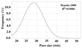
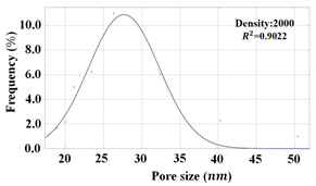
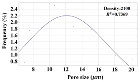
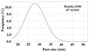
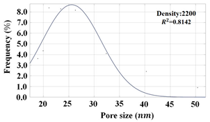
In hydrophilic materials, the internal pore size generally falls within the range of 2 to 50 nanometers. Owing to the interaction of these materials with condensable gases, such as water vapor, condensation occurs within their nanoscale cavities. This capillary condensation mechanism predominantly influences the process of water vapor mass transfer within the material. Test results specify that the pore size of the earth material predominantly lies between 26.00 and 40.87 nanometers and that the contact angle of the material ranges from 51.20° to 66.55°. Considering that the earth material is a representative hydrophilic building substance, its nanoscale pores fulfill the essential criteria for the evaporation of water vapor molecules through capillary condensation. In this section, the correlation between the material’s pore size and the vapor saturation pressure within the capillary is elucidated with the Kelvin equation (refer to Equation (4)) to deepen the understanding of the capillary condensation process.
where
r denotes the radius of curvature, m;
pr represents the capillary vapor saturation pressure, Pa;
p reflects the plane of the saturated vapor pressure, Pa;
γ designates the surface tension of the liquid, and the surface tension of liquid water droplets is provided in
Table 6;
ρ embodies the density of the liquid, kg/m
3;
T refers to the temperature, K; Mis stands for the relative molecular mass of the liquid, 18.02; R expresses the universal gas constant, 8.31 J/(mol-K);
φ indicates the contact angle, with the range of values from 0.357 to 0.638, as detailed in
Table 5.
The Kelvin formula provides a foundational understanding of the correlation between pore diameter, temperature, and the ratio of saturated vapor pressure within a capillary compared to that at the interface of earth material. This relationship assists in comprehending the behavior of moisture within earth structures. In this analysis, the relationship between saturated water vapor force and partial water vapor pressure at the occurrence of capillary condensation within the earth material was investigated with pore diameter and temperature as variables. These conditions are critical for capillary condensation to manifest in the microscopic pores of the material.
Continuous monitoring of the earthen wall temperature enables the maintenance of internal temperatures within the specified range of 12 to 60 °C [
22,
23,
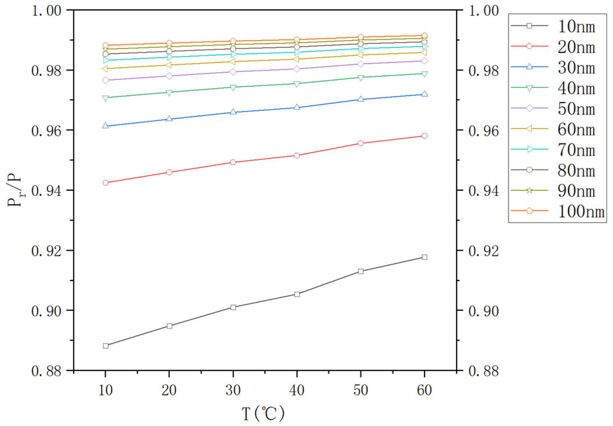
24]. A series of temperatures (10 °C, 20 °C, 30 °C, 40 °C, 50 °C, and 60 °C) were selected for the study to evaluate the influence of temperature on the ratio of saturated vapor pressure. In conjunction, the distribution of pore diameters within the internal pores of the earth material was examined, along with the threshold conditions essential for the formation of capillary condensation. Thus, pore diameters of 10, 20, 30, 40, 50, 60, 70, 80, 90, and 100 nanometers were selected for analysis. The correlation images, derived from Equation (5), were fitted, as depicted in
Figure 6 and
Figure 7.
Capillary condensation occurs within earth materials at atmospheric pressure when the temperature remains constant. As the temperature gradually increases, the saturation vapor pressure required for capillary condensation correspondingly rises, resulting in the lessened likelihood of this phenomenon. The distribution of vapor pressure ratios implies that the pore diameters of the material fall within the range of 10 to 50 nanometers. Capillary condensation appears when the water vapor pressure is approximately 0.86–0.96 times that of the horizontal vapor pressure. Meanwhile, smaller pores exhibit a higher probability of this occurrence. As the pore diameter approaches 100 nanometers, the vapor pressure ratio nears unity, suggesting that the pore structure of the earth material exerts minimal influence on the capillary condensation phenomenon. Moreover, the incidence of capillary condensation within earth materials is significantly correlated with the material’s contact angle. Generally, an increase in the surface adhesion of the earth corresponds to enhanced hydrophilicity and hence the increased probability of capillary condensation occurring.
Figure 7 suggests that an increase in the temperature of water vapor leads to an elevation in activity, which, in turn, raises the ratio of saturated vapor pressure in the capillary relative to that of the horizontal plane of the steam. Consequently, the relevance of capillary condensation diminishes. Within the pore diameter range of 10 to 50 nm, the sensitivity of the capillary condensation phenomenon to alterations in pore diameter is heightened. Nonetheless, this sensitivity declines with the growing pore diameter. Additionally, the impact of temperature on capillary condensation may be progressively disregarded concerning pore diameters ranging from 60 to 100 nm.
The findings of the aforementioned study specify that the saturated vapor partial pressure of capillary condensate formed within the nanoscale pores of earth materials is approximately 0.86–0.96 times the vapor partial pressure at the surrounding plane. Thus, capillary condensate can form spontaneously at room temperature and pressure. The primary distinctions between this phenomenon and condensation on the surfaces of building materials can be outlined as follows.
- -
Condensation predominantly manifests in the surface layer of the building walls, while capillary condensation occurs within the walls themselves.
- -
Condensation is contingent upon reaching the dew point temperature, whereas capillary condensation does not depend on such temperature limitations.
4.3. Periodic Interface Effects in the Nanovoids of Earth Construction
The impact of capillary condensation and evaporation in the nanovoids of earthen walls on the indoor thermal environment of earth buildings was analyzed with measured indoor and outdoor thermal data from earth dwellings in the Jiaozuo area of Henan Province as a case study. Relevant computational analyses were performed, and these results were compared with the indoor thermal environment data of concrete dwellings under the same conditions [
21,
25]. The aim was to demonstrate how the mechanisms of capillary condensation and evaporation, along with their associated latent heat, regulate the indoor thermal environment of earth buildings.
In this subsection, the microstructure of earth materials and the subsequent occurrence of capillary condensation and evaporation phenomena are described, followed by the integration of the regularity of the alteration of indoor heat and humidity environmental parameters of earth buildings, to objectively establish the responsive relationship between the two. The scope of the research falls within the domain of qualitative science. Several aspects require clarification before outlining the regulatory mechanism of capillary condensation and evaporation phase change latent heat within the indoor thermal environment of earth buildings. First, the enclosure serves as the principal medium, through which energy interactions between the building and its external environment are facilitated. This process is characterized by the transfer of energy from regions of higher potential to those of lower potential. Second, the thermal performance of the walls suggests that the outdoor environment exerts a significant influence on the indoor temperature and humidity levels. The trends of these variables are isotropic, implying that during daylight hours, ambient temperatures increase, and humidity levels decrease as a result of solar radiation. Isotropy refers to this diurnal pattern, wherein temperatures rise during the day and fall at night, also under the influence of solar radiation. However, the sensitivity of the indoor environment to these fluctuations is modulated by the thermal inertia of the enclosure structure, demonstrating a certain degree of hysteresis. Third, alterations in wall moisture content, relative to the rapid fluctuations in wall temperature, transpire at a delayed rate. Consequently, the analysis temporarily omits the impact of changes in material moisture content on latent heat associated with capillary condensation and evaporation phase changes.
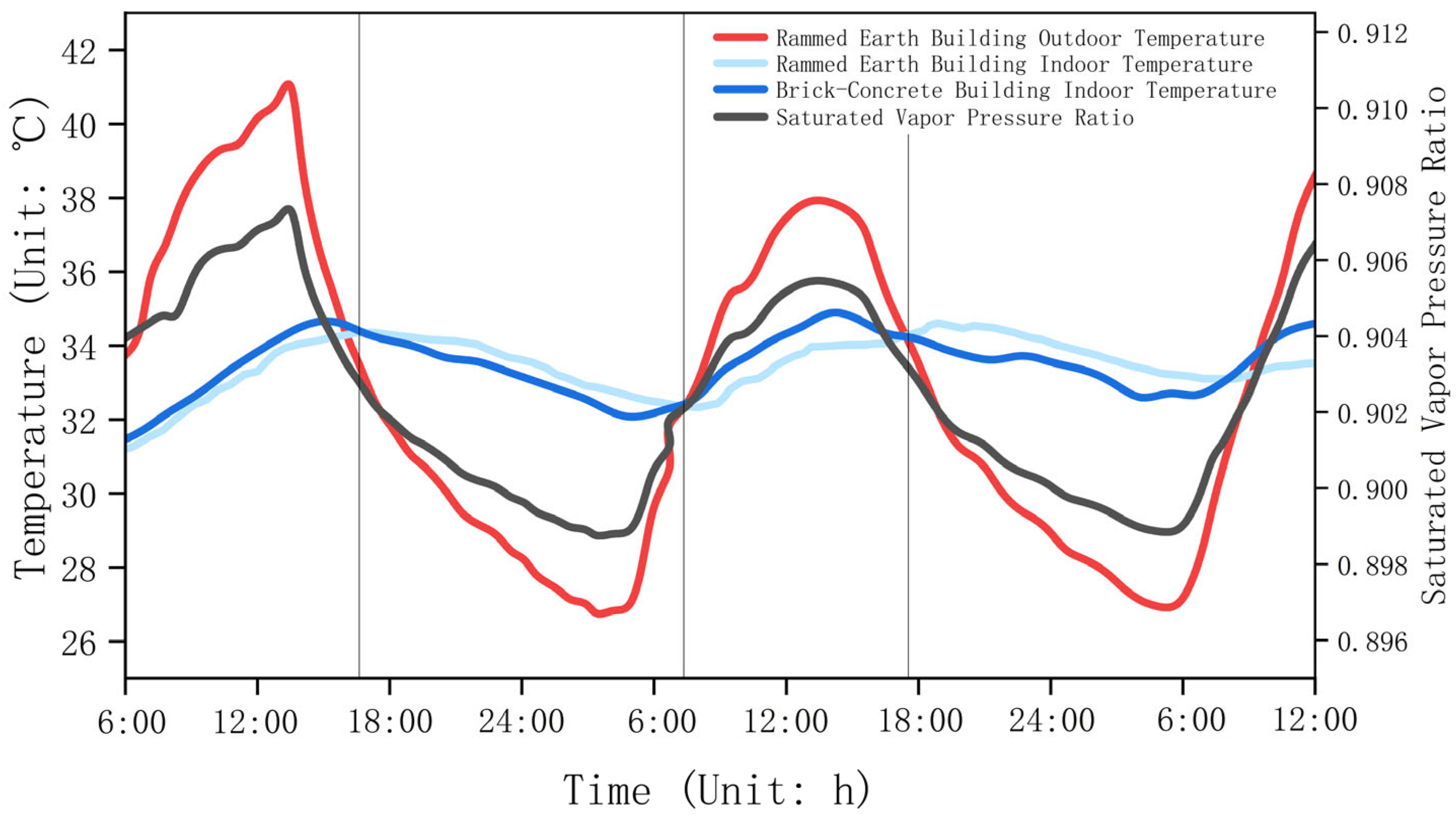
The indoor and outdoor thermal environments of earth and brick buildings in a village in Henan Province were measured over three days, from the 26th to the 29th of July. The measurement equipment consisted mainly of an automatic weather station (PC-4 type), a temperature test module (TR-72U), as well as a multi-channel temperature and heat flow sensor (JTNT-A). The results of the environmental data testing are illustrated in
Figure 8. Then, a detailed comparative analysis was conducted on the temperature conditions experienced by the earth building and the concrete block building during the peak summer months. This analysis focuses on two key metrics (temperature fluctuations and phase delay times), which are critical for understanding indoor thermal comfort. The earth building demonstrates a temperature fluctuation range of 31.4–34.2 °C. Within this range, the temperature amplitude is approximately 2.8 °C, reflecting small variations in indoor temperatures throughout the day. Additionally, the phase delay time, which measures the lag between outdoor and indoor temperature changes, is approximately 3 h. This extended phase delay suggests that the earth building maintains more stable indoor conditions despite external temperature shifts. In contrast, the concrete block building presents a slightly higher temperature fluctuation range of 31.6–35.2 °C. The temperature amplitude in this structure is approximately 3.6 °C, specifying larger variations in indoor temperatures, which could affect occupant comfort. Moreover, the phase delay time for the concrete block building is around 1 h, implying a quicker response to outdoor temperature changes yet potentially less stability in indoor conditions.
These findings underscore the superior thermal performance of earth buildings since they provide enhanced indoor temperature stability. This conclusion is consistent with a substantial body of research that highlights the effectiveness of earth materials in moderating indoor thermal environments [
26,
27,
28]. This stability is particularly valuable for promoting occupant comfort and energy efficiency within these structures.
Based on the measured environmental data, the water vapor partial pressure ratio required for capillary condensation within the earthen wall over a 48 h cycle, along with its responsiveness to both the indoor and outdoor environments, was calculated, as presented in
Figure 8. In the built environment, both the indoor and outdoor settings of buildings undergo regular and predictable changes, generally characterized by simple harmonic wave patterns. For instance, outdoor air temperatures gradually increase between 4:00 a.m. and 2:00 p.m. (
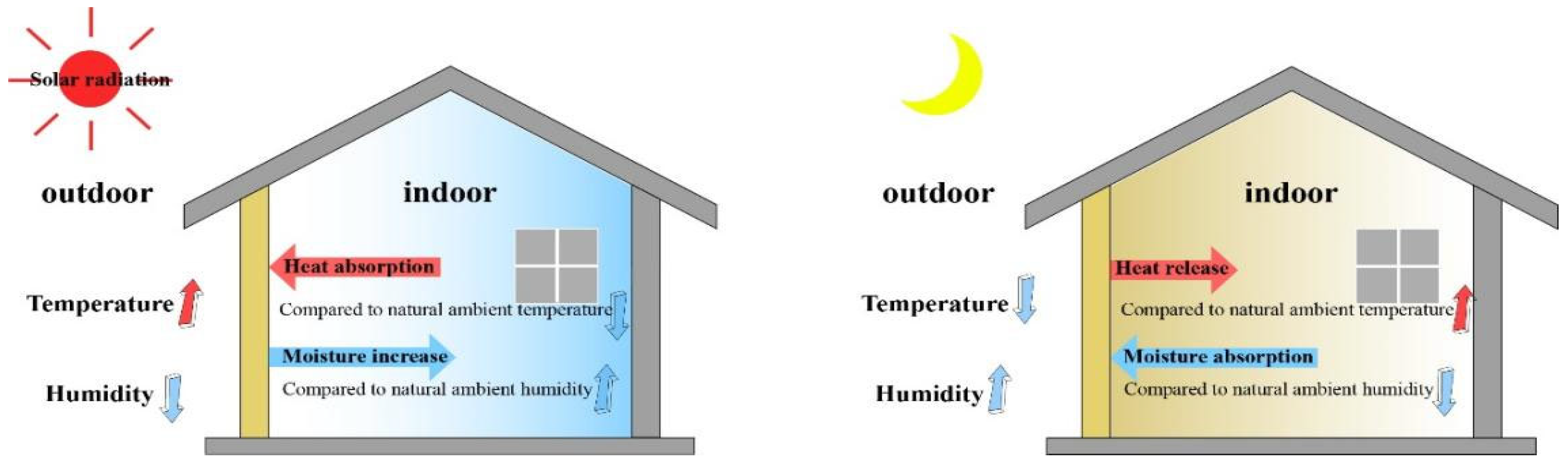
Figure 8). This increase in temperature is primarily provoked by solar radiation, which significantly heats the earthen wall of the building. The rising temperature of the wall brings about a heightened ratio of the partial pressure of water vapor required for condensation and evaporation within the nanopores of the wall material. During this period, capillary evaporation of water molecules occurs, and hence moisture from the wall evaporates and absorbs heat from the indoor environment, contributing to the creation of a cooler indoor climate. This process affects temperature while leading to the release of water vapor back into the atmosphere. A gradual decline in outdoor temperatures appears as the day progresses into the evening and the next 24 h. This decrease in temperature correlates directly with a drop in the temperature of the earthen wall. Alongside this cooling phenomenon, the capillary condensation/evaporation pressure ratio also diminishes, facilitating the nanopore capillary condensation phenomenon in the wall. As a result, the wall releases the stored heat into the indoor air while simultaneously absorbing moisture from the surroundings. This dynamic interaction establishes a hygrothermal equilibrium within the building. During the nighttime, the earthen wall exhibits hygroscopicity and exothermic behavior, which retains heat that can be gradually released. During the day, the wall absorbs heat and releases moisture, leading to fluctuations in indoor environmental conditions. This intricate balance between moisture and temperature profoundly influences indoor comfort and energy efficiency (
Figure 9).
Capillary condensation and evaporation processes within earthen walls offer a compelling scientific explanation for the enhanced thermal inertia and thermal lag observed in earth buildings compared to conventional concrete block structures. As illustrated in
Figure 8, the outdoor ambient temperature peaks around 14:00, signifying the height of solar heating for the day. Conversely, the maximum indoor temperature of the earth building is not reached until approximately 17:00, leaving a significant delay of about three hours between these two temperature readings. During the interval from 14:00 to 17:00, the outdoor temperature begins to decline, influencing the temperature and water vapor partial pressure within the earthen wall. This decrease initiates capillary condensation within the nanopore spaces of the wall. The resulting phase change from vapor to liquid releases latent heat into the interior space, contributing to a sustained increase in the indoor temperature of the earth building. As the outdoor ambient temperature continues to fall, the indoor heat gradually dissipates because of the established temperature gradient between the interior and the exterior. The peak indoor temperature, which was reached at 17:00, signifies a balance point where the heat lost from the building equals the heat released from the condensation occurring within the earthen wall. Following this peak, the indoor temperature starts to decline with further decreases in the ambient temperature. However, this decline, which is mitigated by the heat retention capacity provided by the ongoing condensation effects of the earthen wall, is considerably less pronounced in concrete block buildings.
This phenomenon lays a scientific foundation for understanding why earth buildings often maintain lower daytime temperatures and higher nighttime temperatures compared to their concrete counterparts. The unique thermal properties of earth, including its ability to absorb, store, and gradually release heat, bring about a more stable indoor climate, highlighting the advantages of using sustainable building materials in energy-efficient design.
5. Conclusions
In this study, the phenomenon of capillary condensation and evaporation occurring within the nanopores of earth materials was characterized, followed by the introduction of Kelvin’s equation in conjunction with the microstructural characteristics of these materials, such as porosity, pore size distribution, and pore volume. Mathematical modeling, the control variable method, and various analytical techniques were employed to reveal that the superior stability of the indoor thermal environment in earth buildings can be attributed to the periodic occurrence of latent heat phenomena associated with capillary condensation and evaporation within the nanopores of earthen walls. The crucial conclusions are drawn as follows.
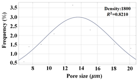
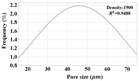
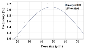
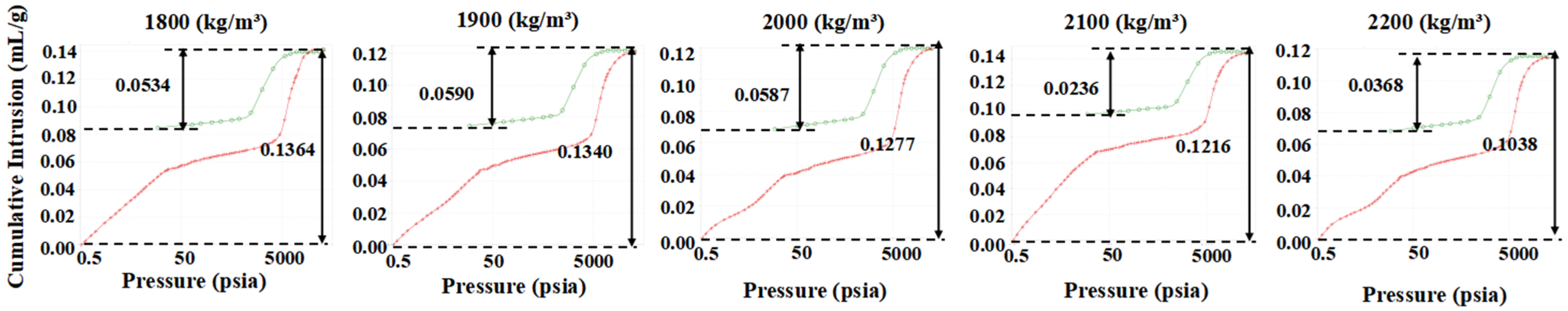
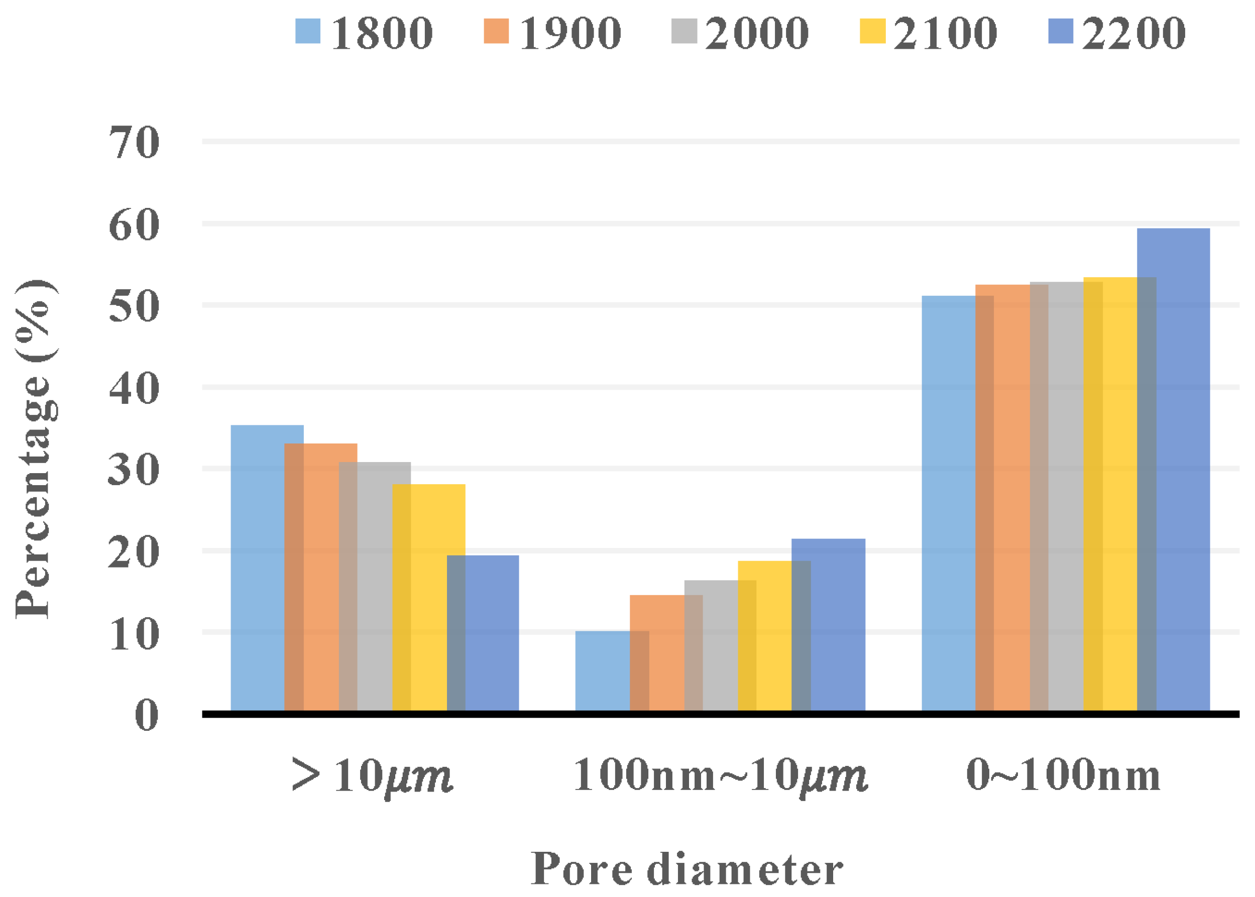
The mean pore size of the earth material is approximately 26.00–40.87 nm, conforming to a Gaussian distribution function. The earth contains numerous interconnected nanoscale pores connecting to the external environment. However, these pores occupy only 18.5–43.9% of the total pore volume, with a significant proportion of the pores inadequately sealed. These pores are undetectable at ambient temperature and pressure, substantially influencing the accurate assessment of the thermal properties of earth materials.
Under standard temperature and pressure conditions, water vapor undergoes capillary condensation or evaporation within the nanopores of earth materials. This condensation phenomenon is more pronounced in materials characterized by smaller pore sizes and lower temperatures. Moreover, cyclic environmental temperature and humidity exert particularly significant effects on the water molecules present within the nanoscale pores of earthen walls. During daytime, evaporation occurs, absorbing heat and releasing humidity. During nighttime, condensation occurs, releasing heat and absorbing humidity. This continuous process effectively regulates the temperature and humidity of the interior of earth buildings. The former maintains a more stable indoor environment, as specified by a comparative analysis between earth buildings and concrete block structures. Furthermore, the micro-interface effect of earth materials explains the thermal hysteresis phenomenon observed in earth buildings.
In conclusion, interdisciplinary research methodologies were utilized in this study to establish a correlation between the latent heat effects of capillary condensation and evaporation in the nanopores of earth materials and the macroscopic performance of earthen structures. The results suggest that the stability of the indoor thermal environment in earth buildings considerably exceeds that of conventional building materials. This stems from the superposition of the thermal performance of solid-phase materials and the latent heat performance facilitated by capillary condensation and evaporation. Nonetheless, the current research does not quantify the impact of this latent heat on the indoor thermal environment of the building. Therefore, technical tools, such as scanning electron microscopy and deep learning, will be incorporated in subsequent studies to create a morphological model of dynamic capillary condensation and to quantify the latent heat of phase transition within the earth material.


