1. Introduction
Waste management is a growing concern at the national and European Union (EU) levels as well as on a global scale. About 2.12 billion tons of waste are produced globally every year, and more than half of this amount—1.3 billion tons—is made up of food waste. In this regard, the most disturbing fact is that about 33% of global waste is not managed in an environmentally safe and sustainable way, avoiding any resource circularity [
1,
2]. Moreover, by mid-century, global waste is expected to reach a staggering 3.40 billion tons a year, representing an increase of more than twice the global population growth during 2025–2050 [
3].
As for the EU, in 2022, the total waste generated in the region amounted to 2233 million tons or 4991 kg per capita. Only 39.2% of waste was recycled, and 32.2% was landfilled [
4]. Therefore, it is obvious that the global untreated waste percentage correlates closely with the EU’s untreated waste percentage.
Even though large amounts of global and European waste end up in landfills without any further treatment, the traditional method of disposing of waste in landfills is no longer deemed sustainable due to its impact on the environment [
5,
6]. Waste treatment facilities must move towards a more circular approach to reducing the amount of landfilled waste and, thus, minimising the environmental impact of waste management [
7].
While the EU’s overall landfill rate decreased from 23% to 17% between 2010 and 2022, the total amount of waste generated in the region has continued to increase. As stated above, landfill waste quantities in 2022 were equivalent to about 5 tons of waste per year for each EU inhabitant.
In Europe, relative progress has been made towards diverting waste from landfills for some types of waste, such as household and food waste [
8]. To comply with the objectives of Directive 2008/98/EC [
9], the EU countries must take the necessary measures to increase reuse and recycling of municipal waste to a minimum of 55%, 60% and 65% (by weight) by 2025, 2030 and 2035, respectively [
10].
In 2022, about 1992 million tonnes of waste were treated in the EU. This does not include exported waste but does include the treatment of waste imported into the EU. The reported amounts are therefore not directly comparable with those on waste generation. In 2022, more than half (61.4%) of EU waste was treated in recovery operations: recycling (40.8% of the total treated waste), backfilling (14.2%) or energy recovery (6.4%). The remaining 38.6% was either landfilled (30.2%), incinerated without energy recovery (0.4%) or disposed of otherwise (8.0%) [
11].
Significant differences could be observed among the EU countries regarding various waste treatment methods. For instance, some countries had very high recycling rates (Italy, Belgium, and Slovakia), while in others, landfills were the prevailing treatment category (Romania, Bulgaria, and Finland).
In line with the provisions of Directive 1999/31/EC, Latvia adopted the National Waste Management Plan for 2021–2028 [
12]. The effectiveness of waste prevention measures can be evaluated based on the following quantitative indicators, which are comparable to the aims for 2028 (see
Table 1).
The plan focuses on increasing the recycling level of each waste type, especially household and hazardous waste. At the EU level, Latvia still sorts and recycles an insufficient amount of waste. This applies not only to solid municipal or other types of waste but also to secondary resources that can be recovered from landfills [
13], as about 47.8% of all waste in Latvia still ends up being landfilled [
14].
One of the most promising secondary waste resources to tackle in Latvia is LFG—a product of organic waste decomposition and degradation processes that depend on several factors. Oxygen promotes aerobic respiration, which increases CO
2 production, while oxygen at high temperatures favours the formation of VOCs [
15]. LFG potential can be derived from the composition of the substrate, which varies from site to site. The rate of LFG production can be determined using empirical data or anaerobic degradation tests. In one year, 200–300 m
3/ton of solid municipal waste produces 1–40 m
3/ton CH
4 [
16].
The obvious benefit of LFG usage is that it can be purified and used for many different purposes—for instance, for powering gas cogeneration and trigeneration units [
17]. The collection and purification of LFG, which is formed in waste deposit sites by bacteria breaking down organic waste, offers significant benefits in recovering resources that otherwise would be lost. This approach provides an efficient solution for waste management and positively contributes to the development of more sustainable and environmentally friendly energy solutions. When ignored and untreated, gas generated in a landfill deposit can threaten the environment. Therefore, its capture, treatment, safe neutralisation, and use for energy purposes are important. Also, purifying LFG before its use as fuel for gas engines in cogeneration units is crucial for their proper operation for electricity and heat generation [
18]. Using unpurified LFG as fuel can shorten the engine’s operational timespan to around 100 h, even in the case of frequent changes of lubricating oil [
19].
LFG purification methods and strategies should be carefully considered and chosen for each site. Usually, the choice of a multistage configuration of an LFG purification strategy is grounded in current best practices and the scientific literature. As noted in [
20], there is a large number of purification and upgrading technologies available, but many of them are energy-intensive and best suited only for large-scale systems.
To enable its safe and efficient use as an energy source or for wider use and grid injection, LFG must undergo purification processes. A number of well-established techniques are used to treat LFG, each with distinct mechanisms and applicability depending on the gas’s composition, required purity, and economic considerations. One of the most widespread techniques is Pressure Swing Adsorption (PSA). PSA separates gases based on their differential adsorption on a solid substrate at varying pressures. Typically, zeolites or activated carbon are used to selectively adsorb CO
2 and other impurities under high pressure and release them at low pressure, thereby enriching the methane content. PSA systems operate near ambient temperatures, making them energy-efficient and scalable for biogas and LFG upgrading to pipeline standards [
21].
Activated carbon adsorption is another essential method, particularly effective in removing VOCs, H
2S, and siloxanes. Activated carbon, owing to its high surface area, adsorbs trace contaminants through physical interactions. However, this method is sensitive to humidity, as excessive moisture can reduce its adsorption capacity. Pre-drying the gas is often necessary, and the spent carbon must be periodically replaced or regenerated to maintain efficacy [
22]. Wet scrubbing, or chemical absorption, again involves the contact of LFG with a liquid reagent, such as sodium hydroxide or iron salts, which chemically reacts with soluble contaminants like H
2S and ammonia. This method is particularly efficient for high loads of acidic gases. However, it produces a liquid waste stream requiring environmental management [
23]. Despite this limitation, wet scrubbing remains one of the preferred technologies due to its relatively low cost and operational simplicity.
Membrane separation technologies utilize semi-permeable polymer membranes to separate gas mixtures based on their molecular size and permeability [
24]. In LFG treatment, CO
2 and other small molecules permeate through the membrane faster than methane, allowing for CH
4 enrichment. Membrane systems are modular, space-efficient, and well-suited for decentralized applications. They are also increasingly used in tandem with other methods like PSA to achieve high-purity results [
25].
Cryogenic separation, though less common in small- and mid-scale operations due to its high energy demand, is applied when high-purity methane is required. The process involves cooling the gas mixture to very low temperatures, causing components like CO
2 and moisture to condense and separate based on their boiling points. While cryogenic systems are capital intensive, they can be advantageous in high-throughput operations [
26].
An environmentally friendly alternative is biofiltration, which employs microbial communities to biodegrade organic compounds such as H
2S and VOCs. LFG is passed through a biologically active medium—such as compost or wood chips—where microorganisms metabolize the contaminants. Biofilters are particularly useful for odour control and low-flow applications, though they may not be suitable for high concentrations or variable loads [
27]. In some advanced systems, again, catalytic and sorption hybrid processes are employed. Here, harmful compounds such as H
2S are first oxidized using a catalyst and then removed by adsorption onto solid supports like alumina or carbon. These hybrid processes are particularly relevant for LFG-to-hydrogen conversion or when preparing gas for use in fuel cells [
28].
Another chemical method is solvent absorption, wherein LFG is contacted with selective chemical solvents such as monoethanolamine. CO
2 and H
2S are absorbed into the liquid phase and then stripped via heating. This method is efficient for high-capacity systems and achieves deep purification, but it entails significant operational and maintenance costs due to solvent degradation and regeneration needs [
26].
In all, the choice of LFG purification method depends on multiple factors including gas composition, treatment capacity, end-use requirements, and regulatory constraints. In many cases, hybrid or staged systems offer the most effective solution for producing high-purity biomethane while ensuring environmental compliance and operational reliability.
Different purification methods, for instance, membrane separation systems, can achieve high methane purities exceeding 98%, but require pretreatment to remove contaminants that could damage the membranes [
29].
In Latvia’s case, the purification system must strike a balance between technical effectiveness, cost efficiency, and compatibility with existing landfill operations.
This research also builds on the potential of biological desulfurization, which is a cost-effective and eco-friendly method for bulk H
2S removal, producing valuable byproducts such as elemental sulfur [
30]. However, given the high concentration of siloxanes and VOCs detected in LFG samples from Landfill A, biological methods alone are insufficient. Therefore, the integrated purification system proposed in this study combines multiple technologies to ensure that all relevant contaminants are brought below acceptable thresholds.
By presenting a technically robust and locally adapted purification system, this study contributes to bridging the gap between environmental policy targets and practical waste-to-energy implementation in Latvia. It demonstrates that even medium-sized landfills can become valuable contributors to renewable energy production if equipped with efficient and modular gas treatment technologies. Moreover, the proposed system offers a scalable model that can be replicated across similar contexts in Eastern Europe, where LFG remains an underutilized asset [
31].
Ultimately, this study aligns with the EU Green Deal objectives, supports Latvia’s national energy and climate goals, and promotes the transition from waste disposal to resource recovery [
32]. It underscores the importance of integrating engineering designs with environmental strategies, offering a pathway toward sustainable waste management and circular energy systems.
The study also addresses several critical research and practical gaps, contributing to a regionally significant and original solution within the field of sustainable LFG utilization. One of the primary gaps it fills is the lack of region-specific purification technologies in the Baltics. While numerous studies have been conducted regarding Western Europe and North America [
33,
34,
35,
36,
37], this work is one of the first to target the environmental, technical, and infrastructural conditions specific to Latvia and the Baltics, where LFG still remains an underutilized energy resource.
In addition, this study provides empirical data on the chemical composition of LFG at Landfill A, offering original insights into its levels of hydrogen sulfide, siloxanes, and VOCs. This kind of site-specific data has been largely absent from the literature and is crucial for the design of effective, localized purification systems. Another gap this study addresses is the often-overlooked question of how new purification systems integrate with existing landfill infrastructure. Rather than treating technology as a stand-alone component, this research evaluated its compatibility with current electricity, water, and sewage systems, ensuring that the proposed solution is both technically and economically feasible.
The originality of this study lies in its development of a modular and scalable purification system tailored to medium-sized landfill operations, which are commonly overlooked in large-scale projects. The proposed system includes a multistage purification configuration that has been technically validated to reduce gas impurities below the thresholds required by the EU biomethane standards, demonstrating its readiness for practical deployment. This approach not only meets technical and environmental requirements but also aligns with broader policy objectives, particularly the European Green Deal and Latvia’s national energy strategies.
Importantly, the solution is grounded in real-world data and engineering assessments rather than theoretical modelling, which enhances its applicability. Though designed for Latvian conditions, the system’s modularity and adaptability make it transferable to other Eastern European countries facing similar challenges in LFG management. Thus, this study not only offers a direct response to existing technical deficiencies but also presents a replicable framework that bridges the gap between environmental policy goals and practical energy infrastructure solutions.
The objective of this study was to design, develop, and technically validate a pilot-scale LFG purification system tailored to Latvian environmental and infrastructural conditions, with the aim of enabling the effective removal of key contaminants—such as hydrogen sulfide, siloxanes, and VOCs—from LFG to meet the EU biomethane quality standards and support its potential use in energy cogeneration and gas grid injection.
Research questions of the study include:
What are the key chemical and physical characteristics of LFG generated at major landfill sites in Latvia, and how do they compare to European biomethane quality standards?
Can a multistep, modular purification system effectively reduce hydrogen sulfide, siloxanes, and VOC concentrations in LFG to acceptable levels for energy recovery or grid injection?
How compatible is the proposed LFG purification system with the existing infrastructure of Latvian landfills in terms of energy, water, and sewage requirements?
What are the potential operational, environmental, and policy implications of implementing such a system in Latvia and similar regional contexts?
The hypothesis of the study is formulated as follows: a pilot-scale, modular LFG purification system, designed according to the Latvian LFG composition and infrastructure conditions, can effectively reduce harmful contaminants—specifically hydrogen sulfide, siloxanes, and VOCs—to levels that meet EU biomethane standards, thereby enabling sustainable energy recovery and enhancing alignment with the national and EU renewable energy objectives.
2. Materials and Methods
The main component of LFG, methane (CH
4), is a potent greenhouse gas (GHG) that is at least 25 times more effective than CO
2 at trapping heat in the atmosphere over a 100-year period. It accounts for approximately 5% of the world’s anthropogenic GHG emissions [
37]. Its capture and conversion into usable energy reduces environmental hazards and promotes efficient, circular use of local energy resources. Additionally, the purification of LFG and its use in further energy production is an important step towards the European energy and climate policy goals and is a way to reduce the consumption of imported fossil energy resources [
38].
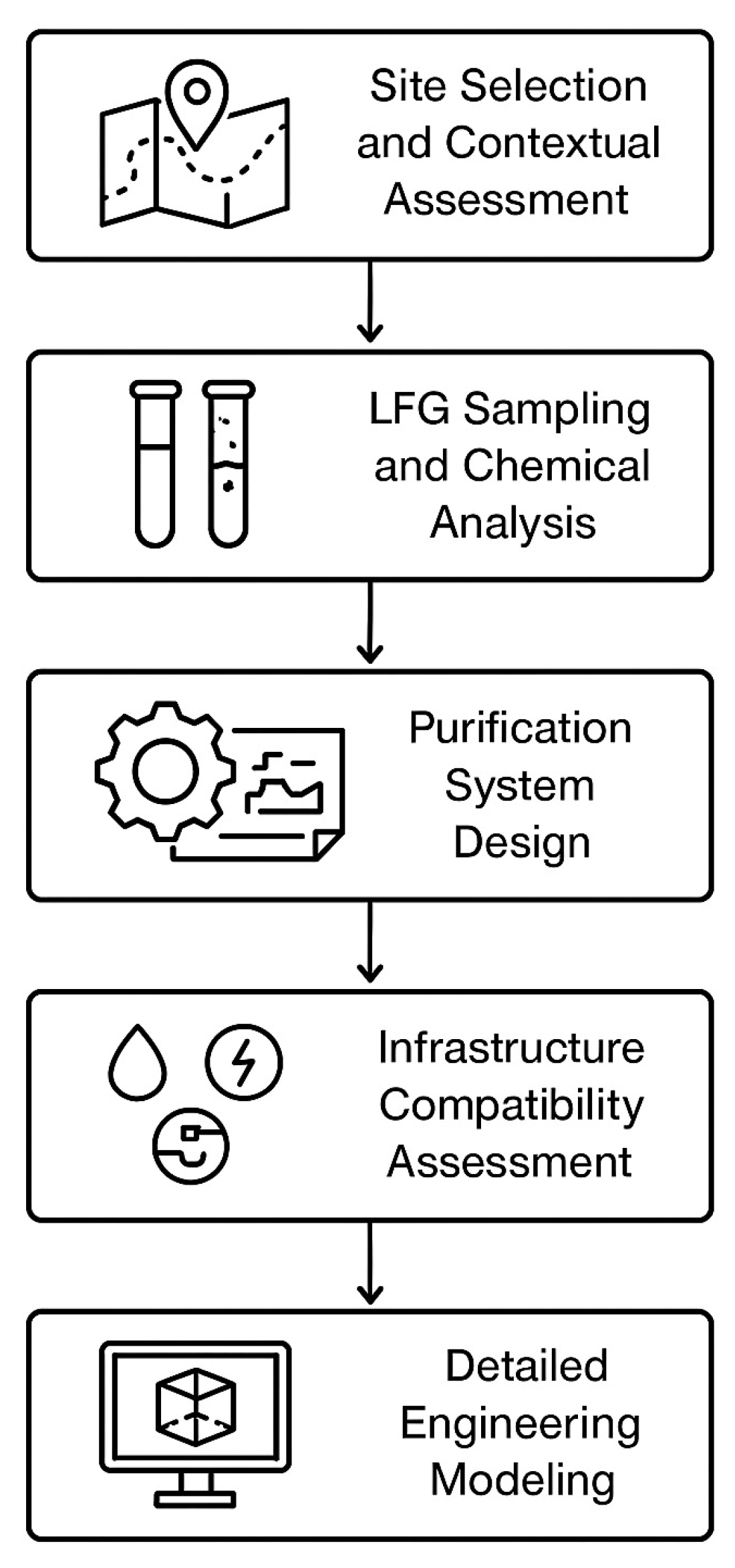
This study developed and assessed a pilot-scale, multistage LFG purification system tailored for Latvian conditions. The methodology was centred around five key components: site selection and contextual assessment, LFG sampling and chemical analysis, purification system design, infrastructure compatibility assessment, and detailed engineering modelling of each purification stage (
Figure 1). The goal was to create a modular, efficient system for removing critical contaminants—specifically, H
2S, siloxanes, and VOCs—to enable broader energy applications and eventual biomethane standard compliance.
The purification prototype was designed with a nominal capacity of 1500 m
3/h and tested using data collected from gas analysis at Landfill A (
Figure 1). Initial measurements showed H
2S levels up to 1063 mg/m
3, siloxanes up to 149 mg/m
3, and VOCs up to 1640 mg/m
3—values significantly above allowable limits for grid injection. The prototype was engineered to reduce H
2S concentrations to below 7 mg/m
3 and siloxanes to less than 0.3 mg/m
3, aligning with EU biomethane standards and making the gas suitable for cogeneration and potential grid use.
In addition to the technical configuration, this study assessed the site’s infrastructure to ensure feasibility. The findings indicate that the landfill’s current electricity supply, water availability, and sewage system are adequate to support the operation of the purification unit, thereby eliminating the need for major auxiliary investments.
2.1. Site Selection and System Context
The purification system was designed for Landfill A, which handles 22% of all waste generated in the country and processes more than 50% of unsorted municipal waste and over 70% of biodegradable waste. Its infrastructure includes reclaimed landfill zones, operational waste disposal cells, a bioreactor, and waste processing and administrative facilities, all situated on nearly 90 hectares. In the facility, LFG is obtained in two ways: from the biodegradable waste processing complex and the waste disposal cells. Landfill A is one of the most modern in Europe, currently developed as a secure waste recycling centre. Landfill A consists of the old, reclaimed waste dump site; waste disposal cells; bioreactor; waste recycling infrastructure; and infrastructure supporting waste management facilities, administration buildings, etc.
According to information on total produced waste in Latvia in 2021, Landfill A managed 22% of total produced waste in Latvia while receiving more than half (55%) of unsorted household waste and 73% of biodegradable waste (BDW) generated in the country [
13].
In 2023, Landfill A demonstrated consistent LFG generation, with monthly production volumes ranging from 100,000 m3 to 255,000 m3. The highest output was recorded in January (255,000 m3) and October (250,000 m3), while the lowest was observed in September (100,000 m3). Throughout the year, CH4 concentrations remained relatively stable, fluctuating between 68.0% and 70.3%. Notably, even during periods of reduced gas volumes, such as in August (120,000 m3) and September, the CH4 content remained high, suggesting a stable degradation process within the landfill. These figures highlight the significant and consistent CH4 potential of the site, supporting the rationale for deploying a purification system aimed at upgrading LFG for energy use and potential grid injection.
On average, Landfill A produced 190,000 m
3 of LFG per month, with CH
4 concentrations consistently exceeding 50%. Future possibilities of biomethane production and injection into the gas distribution network are also under review in Landfill A [
39].
For reference and comparison,
Table 2 demonstrates an average sample chemical composition of LFG. LFG, which is primarily a mixture of CH
4 and carbon dioxide (CO
2), also contains pollutants such as H
2S, nitrogen, and various VOCS (see
Table 2). These pollutants make the gas dangerous for direct use in energy production, as they can cause technical damage, reduce system efficiency, and pollute the environment [
40].
Due to the scale of production and the landfill’s strategic importance, Landfill A was selected for the installation of the purification prototype. Site assessment also confirmed the availability of critical infrastructure—power supply exceeding 500 kilowatts (kW), water flow over 1 m3/h, and sewage capacity of 1 m3/h—which all surpassed the prototype’s operational requirements.
2.2. LFG Composition and Sampling Methodology
Chemical composition analysis of LFG was conducted via systematic sampling and laboratory testing. Gas samples were taken from multiple extraction points connected to the landfill’s gas collection system, with parameters measured in laboratories. Waste composition was also evaluated through a quartering method from sorted waste heaps to determine biodegradable and inert fractions that influence gas generation.
2.3. System Architecture and Design Methodology
The purification prototype was engineered for a nominal gas flow rate of 1500 m
3/h. The system consists of five primary stages: desulfurization, cooling and moisture removal, pressure stabilization via pumping, siloxane removal, and activated carbon filtration. Each component was designed using standard engineering principles and tailored to expected gas loads and contaminant concentrations. Key performance thresholds targeted H
2S concentrations below 7 mg/m
3 and siloxane levels under 0.3 mg/m
3, aligning with the EU biomethane standards (EN 16723-1:2016) [
41].
2.4. Infrastructure and Site Integration Analysis
To ensure practical feasibility, the design included a detailed site integration plan. This encompassed layout mapping of utility connections, gas routing pipelines, and foundation requirements for each purification module. All infrastructure needs were cross-checked against Landfill A’s available resources to avoid excessive retrofitting.
2.5. Performance Evaluation Metrics
Each system module was modelled using design parameters and expected operational conditions. Performance indicators included gas throughput, contaminant removal efficiency, energy consumption, and maintenance intervals. The key targeted outcomes were:
H2S < 7 mg/m3 (achieved via >95% removal efficiency),
Siloxanes ≤ 0.3 mg/m3 (achieved via >99% efficiency),
VOC reduction to meet engine compatibility levels,
Relative humidity reduced to <50%,
Total sulfur concentration post-treatment <30 mg/m3.
System readiness for integration with future PSA or membrane-based biomethane upgrading modules was considered but left outside the scope of this initial pilot study.
3. Results
Landfill A regularly analyses its waste composition and gas quality, ensuring compliance with environmental regulations and waste management requirements. According to the regulations of the Cabinet of Ministers no. 1032 and its category A polluting activity permit, sorted residues and BDW fractions are analysed, determining parameters such as moisture content, biomass percentage, and impurity level [
42].
Landfill A provides composition measurements of sorted residues once every three months, inviting an accredited laboratory to perform this task, which determines the specific weight of each category. When determining the composition of household waste, it is sorted into the following categories: paper and waste containing paper (packaging, cardboard, tetra packs, mixed wastepaper and cardboard etc.), plastic and plastic-containing waste (packaging, film, mixed plastic waste etc.), glass and glass-containing waste, waste containing metals, BDW and biological waste, construction debris and building demolition waste, waste of electrical and electronic equipment, waste batteries and accumulators, textile waste, large waste (at least one external dimension exceeds 50 cm), fine fraction (size of household waste less than 10 mm) and other household waste that does not belong to the categories mentioned previously. As for LFG acquisition, the BDW household and other municipal waste are of special interest. The household waste sampled is fed into a conical stack and divided vertically into four equal parts along two imaginary lines. The two opposite quarters of the conical heap are mixed into one sample in the conical heap, which is then again divided vertically into four equal parts on two imaginary lines, with the remaining two quarters being left out of subsequent operations. These steps are repeated until the desired household waste sample size (5 kg) is reached. At the same time, a laboratory analysis of the LFG composition is performed to determine its chemical makeup and methane levels. Chemical composition of the LFG sample taken from Landfill A normally shows a high level of H
2S, siloxane (Si−O−Si) and VOCS (see
Table 3), which can be compared to H
2S levels in samples taken from other landfill sites and described in the scientific literature [
43].
As shown in
Table 3, the CH
4 content in LFG reaches 55.8%, while CO
2 makes up 37.3% of the gas volume. Oxygen and nitrogen concentrations are 1.1% and 5.8%, respectively. A high concentration of H
2S was found—585 mg/m
3N, which significantly exceeds the usual composition of natural gas and biomethane. Among siloxanes, the highest content was found for decamethylcyclopentasiloxane (D5)—43.1 mg/m
3N, which can critically affect the service life of technological equipment. The total concentration level for VOCs was 913 mg/m
3N, excluding methane. LFG with a 40–60% methane content has an average heating value of 17,765 kJ/N m
3 [
44].
Analyses performed in the certified laboratory confirmed that the composition of the LFG exceeds permissible pollution limits; for example, in H2S and siloxane concentrations. Thus, the gas is not suitable for direct use in energy or biomethane production without prior purification.
The removal of H
2S, siloxanes, and VOCs is an essential step in the landfill purification process to prevent corrosion in equipment such as gas engines, boilers, and pipelines [
45]. Reducing the formation of deposits and mechanical wear ensures the sustainability of technological equipment.
3.1. Site Selection and Compliance
The prototype for the LFG purification system developed by SIA “G2.LV” will be installed for testing at Landfill A’s waste treatment complex. The prototype, with a nominal purified gas flow of 1500 m
3/h, requires approximately 250 m
2 area, which would be made available by dismantling the existing Landfill A’s gas treatment facilities and building new infrastructure elements, especially for the prototype. In addition, it is necessary to construct underground engineering networks to reach the existing and new infrastructure elements. The basic infrastructure availability assessment, which covers the electricity, water and sewage system requirements for installation of the prototype versus available resource connection capacity at the Landfill A complex, is summarised in
Table 4.
A power of 200 kW is required to ensure the prototype’s operation, while the power supply available at Landfill A exceeds 500 kW. Therefore, the available power is more than twice as large as required, thus ensuring a stable and secure supply of electricity, even in cases of possible load fluctuations or growing energy consumption. Such reserved capacity also provides sufficient flexibility for implementing future upgrades or additions.
The prototype operation requires a water flow of 0.8 m3/h, which is significantly less than Landfill A’s available >1 m3/h capacity. This guarantees that the water supply sufficiency will always be met, even if additional water consumption is necessary, for example, for emergency cooling processes.
The prototype requires a sewage disposal capacity of 0.2 m
3/h, while the available capacity of Landfill A exceeds 1 m
3/h. This provides more than a five-fold reserve, which proves the reliability of the system and the ability to absorb additional loads, for example, in emergencies or cases of additional connections. The prototype’s planned location in Landfill A and the complex and infrastructure connection to the prototype’s location are depicted in
Figure 2.
The
Figure 2 shows a schematic of the planned Landfill A complex with different colours showing land use purposes and infrastructures, where various utility connection points, as well as the location of the prototype installation itself, are marked. A black rectangular outline in the middle of the image indicates the planned location of the prototype. The prototype installation site provides sufficient space for equipment deployment, service personnel access and possible future upgrades. The site is also close to the main engineering network connections, thus reducing connection installation times and costs.
The five-step technological process is designed to purify LFG from the Landfill A complex and prepare it for further use in energy production or injection into the gas distribution and/or transportation networks.
Step 1: gas desulfurisation. It removes sulfur compounds, such as H
2S—a colourless, flammable, and toxic odorant—from the gas, which is essential to prevent equipment corrosion and ensure improved gas quality [
46,
47]. The desulfurization unit uses two polypropylene scrubbing towers operating in parallel, each equipped with multi-level spray nozzles and a circulating cleaning solution. The gas enters the towers at the base and rises in counterflow against a sprayed alkaline solution, which absorbs H
2S. The scrubbing towers (Ø2400 mm × 7400 mm height) are connected to an oxidation tank (9.5 m
3), which regenerates the cleaning solution using air diffusion and chemical dosing (via pH and redox sensors). A fiberglass precipitator is employed to separate the sludge and regenerate the scrubbing fluid. The system is designed for a gas flow with a nominal capacity of 1500 Nm
3/h, ensuring H
2S purification with an efficiency of over 95%. The maximum operating temperature of the gas is 60 °C, and the maximum pressure reaches 50 mbar, which meets the requirements for preparing high-quality gas. The towers include a droplet separator (demister) made of polypropylene and a circulation system with three pumps, each with a capacity of 11 kW.
The cleaning solution collected at the bottom of the cleaning tower is transferred to the oxidation tank, where chemical reactions regenerate the solution before it is recirculated through the cleaning tower. An air diffusion system, consisting of a blower and a set of bubble disc diffusers, ensures a constant supply of oxygen, which is essential for the correct operation of the regeneration reactions. The oxidation tank is also fed, using dosing pumps, with the chemicals necessary for the cleaning solution to be effective, thus removing as much H2S as possible. The oxidation tank is polypropylene and measures 1.90 × 2.20 × 9.50 m. It is equipped with one air blower with a capacity of 5.5 kW and bubble disc-type air diffusers, which ensure uniform oxygen distribution. The tank has an integrated level and pH/redox sensors, allowing precise process control. The automatic water replenishment system and reagent dosing pump improve the system’s operating efficiency and ensure optimal oxidation conditions.
The precipitator ensures that the solution flow is continuously recirculated to the settling tank, which separates the solids from the liquid mass under the influence of gravity. The solids form a mass collected at the tank’s bottom and are periodically removed. The control panel, equipped with a programmable logic controller, manages the operation of all devices, instruments and equipment. The precipitator is made of fiberglass and is equipped with an automatic valve for sludge discharge and an overflow device that prevents system overloading. The precipitator dimensions are 2500 × 2500 × 5000 mm and are equipped with a charging pump with a capacity of 0.37 kW. The purpose of this component is to separate the sludge and other solid impurities from the LFG, improving the efficiency of the purification processes.
Step 2: cooling and moisture removal. This step reduces the moisture content in the gas, which is necessary to prevent condensation and prepare the gas for further processing. In the cooling and drying module, gas exiting the scrubbers passes through a shell-and-tube heat exchanger that reduces its temperature and facilitates moisture removal. Condensate is separated into a fully insulated chamber. The system includes a recirculating water loop and an LFG blower to maintain flow and pressure consistency, as well as options for adding energy recovery components.
The system uses a high-efficiency shell-and-tube heat exchanger and a fully insulated condensate separator. This helps to reduce the LFG temperature to a level where water vapour condenses, thereby removing both moisture and harmful impurities that could negatively affect subsequent equipment. The equipment is pre-assembled and skid-mounted, allowing quick installation and reducing installation time and costs. The system has a built-in cooling water circulation cycle and a gas blower, which provides dried gas at optimal pressure. In addition, energy recovery modules, after-treatment heaters, and activated carbon modules can be added to the system, increasing the versatility and efficiency of the equipment and ensuring higher gas quality.
Step 3: directing through a pumping station. The pumping station ensures a steady gas flow and pressure throughout the purification process, which is critical for maintaining optimal conditions for gas transfer and purification. The gas is stabilized via a modular pumping system designed to maintain nominal flow and pressure, accommodating both positive displacement and centrifugal pump options. This step ensures uninterrupted flow through the downstream purification stages and enhances safety and environmental compliance by minimizing fugitive emissions.
An effective LFG pumping station prevents the emission of methane and other gases into the atmosphere, thereby reducing odour, harmful gas effects on the environment and the risk of explosive conditions. This functionality is critical to comply with environmental protection standards. The design of a pumping station considers energy efficiency, the ability to handle aggressive and corrosive substances, and the durability of the equipment in difficult operating conditions. A properly selected and maintained pumping station can significantly reduce operating costs and ensure sustainable operation. The equipment used in LFG pumping stations, such as pumps, vacuum and pressure control systems, and control panels, provides complete control over gas extraction and transportation, thus contributing to efficient and safe operation.
Step 4: removal of siloxane compounds. Siloxanes are VOCS that can cause deposits and damage to equipment components such as engines and catalytic converters. Their removal is important to ensure efficient gas utilisation. The siloxane removal system, developed by “ANKA Yenilenebilir Enerji (Istanbul, Turkey)” [
48], consists of two regenerative adsorption columns operating alternately. Each column is filled with proprietary adsorbent material and is regenerated through a controlled heating cycle. The system achieves up to 99% efficiency in siloxane removal, reducing concentrations to below 1 mg/m
3. The modular configuration ensures continuous operation and allows for scalability. Siloxanes are common in LFG because they are found in personal care products, detergents, and silicone products [
49]. When LFG is used as fuel in engines, turbines, or other combustion systems, siloxanes can form deposits of silica (SiO
2) or silicate (SiO
4−x) that can cause significant damage to the equipment [
50]. In contrast, when LFG is introduced into the general gas supply network, its quality requirements allow only trace amounts of siloxanes. The operating principle of the siloxane removal system is based on a filtration and adsorption process, which ensures the purification of raw biogas from siloxanes with an efficiency of up to 95%. The system is made up of two filters containing specialised adsorption materials for the removal of siloxanes.
The system includes two filters that operate in sequence, ensuring continuous operation. When one filter reaches its adsorption capacity, the second filter, which has already been regenerated, is automatically activated. This modular design promotes scalability and reduces pressure losses, improving the overall operating efficiency of the system. The system uses a special heat regeneration process that allows for the reuse of filters. This technology reduces operating costs and increases sustainability, making the system suitable for long-term operation. The system not only reduces the siloxane content but also improves the quality of the gas, making it suitable for use in various energy systems, such as cogeneration plants. The system provides LFG flow treatment with a nominal capacity of 1500 Nm3/h. Such a specification allows the system to effectively reduce harmful contaminants in the gas and ensure its safe use. The system consumes an average of 220 kilowatt-hours of electricity per day.
Step 5: activated carbon filtration. The filter effectively removes residual pollutants such as VOCs to ensure the highest quality of purified gas. The final purification stage involves stainless steel activated carbon filters, designed to capture residual VOCs, odorous compounds, and any remaining trace impurities. These filters are easy to maintain, chemically resistant, and capable of operating under varying gas pressures and contaminant loads. They are vital for polishing the gas before use in sensitive combustion systems. The main operating principle of these filters is adsorption, where the activated carbon material effectively attracts and accumulates harmful compounds, preventing their release and improving gas quality [
51]. Activated carbon filters are made of stainless steel, which highly resists corrosion, wear and chemical attack, making them suitable for long-term use in difficult conditions.
The filters provide high pollutant removal efficiency, which is especially important for protecting turbines, engines and other power generation equipment from damage. Activated carbon filters are designed to operate in various gas flow regimes and concentration ranges, making them adaptable to different industries and needs. These filters provide easy maintenance and, if necessary, allow for the replacement or regeneration of filter elements. Activated carbon can absorb many pollutants before it becomes saturated, at which point the filter material must be replaced or renewed.
Activated carbon filters reduce odour emissions and improve air quality, extending the life of energy generation equipment by reducing damage caused by pollutants. Regular maintenance of the filters and their regeneration options provides a sustainable and cost-effective solution for LFG management.
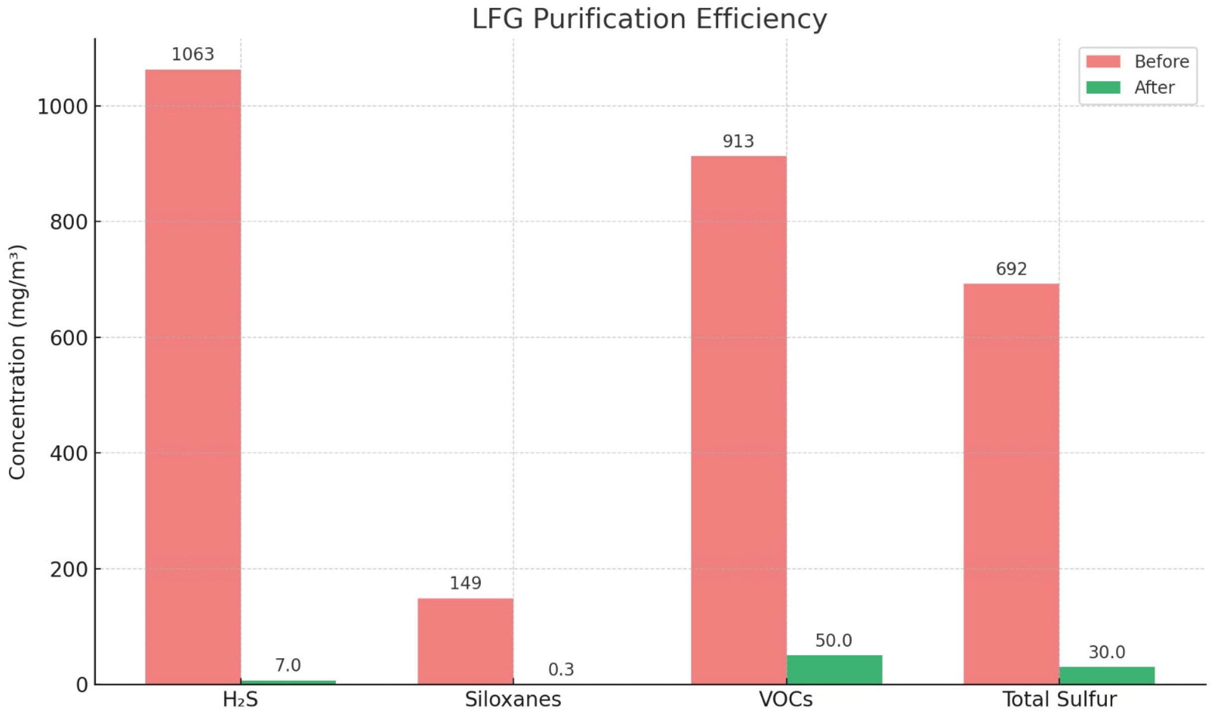
The overall expected LFG purification efficiency is depicted in
Figure 3.
Such hybrid, multi-stage LFG purification technology offers a superior approach to LFG treatment by combining the strengths of multiple purification methods to overcome the limitations inherent in any single technology. This integrated approach enhances the overall process efficiency, pollutant removal rates, and adaptability to varying gas compositions and flow conditions.
Individually, the presented technologies are highly effective under specific conditions; however, they may exhibit reduced performance when applied to complex or fluctuating LFG streams.
Hybrid technologies also enable staged treatment, where each step is optimized for a specific contaminant class. This modular design not only improves removal efficiency but also extends the operational lifespan of downstream components. Moreover, hybrid systems provide greater resilience to operational disturbances, such as sudden changes in gas composition or the flow rate, which are common in landfill environments. Their flexibility allows for easier compliance with regulatory standards for biomethane injection into grids or for combined heat and power (CHP) applications. Overall, hybrid LFG purification systems are superior due to their multi-contaminant removal capability, process optimization, operational stability, and improved economic viability.
However, for purification of LFG to the level of biomethane, pressure swing adsorption or other additional gas purification technology would be necessary [
52], which is not considered in this study. The gas sample analysis showed that, regarding biomethane-level gas purity requirements, two parameters—H
2S and silicon compounds—are critically exceeded (see
Table 5).
3.2. Evaluation of the Gas Purification System’s Efficiency
The planned capacity of the LFG purification installation in the Landfill A complex is 1500 m
3/h, and it will be designed to achieve the following LFG purity parameters (
Figure 4):
H2S: removed to a concentration not exceeding 7 mg/m3, which corresponds to the quality indicators of biomethane. In cogeneration plants equipped with flue gas catalysts, the permissible H2S level is below 200 mg/m3, while in cogeneration plants not equipped with the catalyst, the H2S level can be maintained below 700 mg/m3. Such a purification level prevents corrosion in the plants and protects the operability of components.
Siloxanes: removed to a concentration of ≤0.3 mg/m3. This level ensures that the gas does not harm the sustainability of the equipment and reduces the formation of siloxane deposits in engines.
Humidity: the gas is dried to a relative humidity of less than 50%, and the dew point is lowered below 180 °C. This is important to avoid condensation and ensure efficient gas use.
Sulfur: after desulfurisation, the total sulfur concentration in the gas does not exceed 30 mg/m3, which meets the EU gas quality requirements.
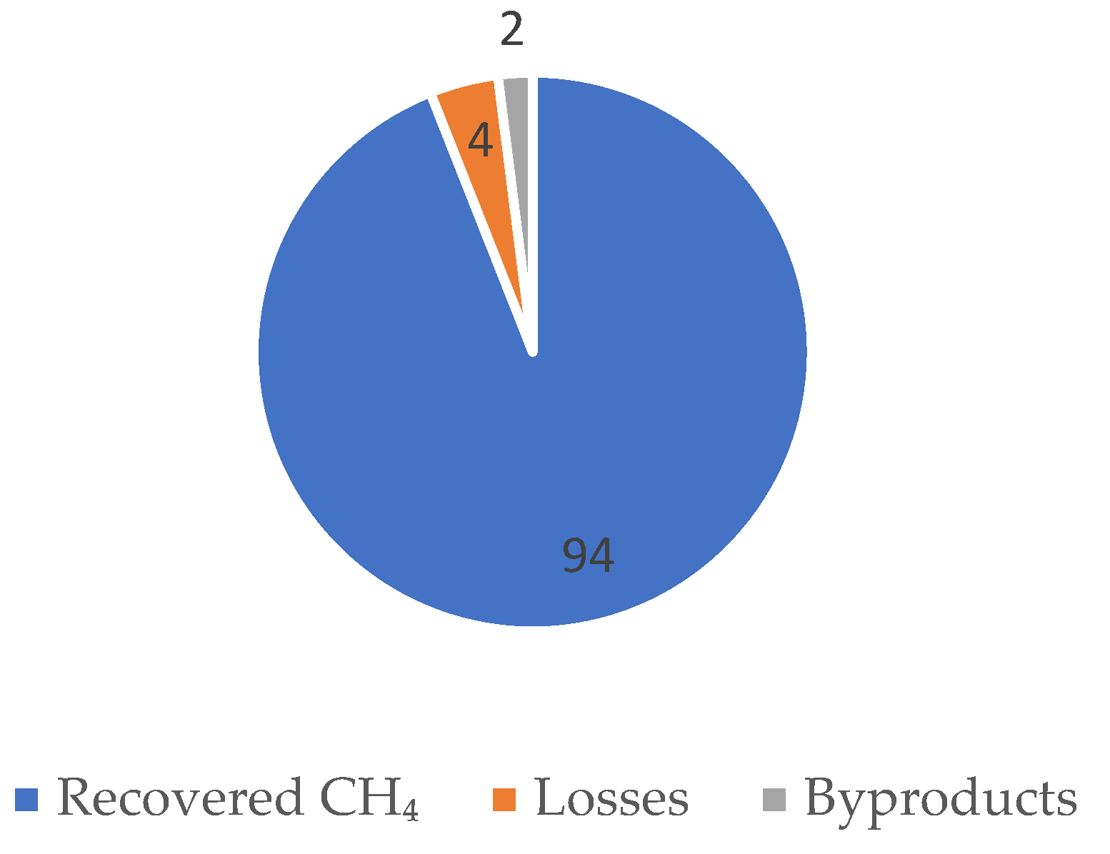
In addition, the total CH4 recovery is expected to exceed 95%, with losses and byproducts comprising a miniscule percentage.
Figure 4.
CH4 recovery rate (%).
Figure 4.
CH4 recovery rate (%).
3.3. Future Testing Plan
The future testing plan for the LFG purification system will be carried out in three structured phases to ensure comprehensive performance validation and optimization prior to potential full-scale deployment (
Figure 4).
The first phase will involve the commissioning of a modular pilot purification system at Landfill A. During this phase, initial gas composition data will be collected to establish a performance baseline, including concentrations of CH4, CO2, H2S, VOCs, siloxanes, and moisture. System parameters such as flow rate, inlet pressure, and operating temperature will also be recorded to define the standard operating conditions.
In the second phase, the system will undergo a continuous 60-day operation cycle to evaluate its performance under real LFG conditions. This phase is critical for identifying the system’s behaviour under variable gas flows and contaminant loads. The gas composition will be monitored before and after each treatment stage using a combination of gas chromatography and online sensors. Removal efficiency for each contaminant will be quantified, while breakthrough curves for activated carbon and saturation dynamics will be studied to determine the optimal replacement interval of the sorbent materials. Energy consumption data will be collected to assess the system’s power demand relative to its purification output.
The third phase will focus on system optimization and comparisons with modelled predictions. Process parameters, including adsorption contact time, adsorbent quantity, and operating pressure, will be systematically adjusted to identify the most efficient and cost-effective operating configurations. The empirical results will be analysed using mass balance calculations and statistical modelling, and benchmarked against performance data from similar systems implemented in the EU. This comparative analysis will enable assessment of the system’s competitive positioning and scalability.
Ultimately, the testing process will produce a comprehensive performance report including removal efficiencies, methane recovery rates, and energy consumption figures. Additionally, a preliminary environmental impact estimate will be generated, focusing on greenhouse gas reduction potential. A cost-benefit assessment covering maintenance cycles and consumable material costs will also be included. Together, these outputs will support the refinement of system design and inform recommendations for broader application of the technology in regional LFG management strategies.
4. Discussion
The proposed LFG purification system is designed to meet stringent performance targets, aligned with the EU biomethane quality standards. The system’s primary expectation is to reduce H2S concentrations to below 7 mg/m3, siloxanes to ≤0.3 mg/m3, and total sulfur content to <30 mg/m3. In addition, the system is expected to lower gas humidity to <50% relative humidity and maintain a dew point below −18 °C. These metrics are crucial for ensuring the suitability of purified LFG for energy recovery applications, including combined heat and power (CHP) and potential grid injection, as per EN 16723-1:2016 standards.
Benchmarking of system performance will involve multiple levels of validation. First, in situ gas composition analysis will be conducted both pre- and post-purification using certified laboratory methods. These analyses will be benchmarked against regional and international standards to ensure compliance. Second, the system’s operational data—such as flow rate, energy consumption, pressure levels, and removal efficiency—will be continuously monitored using SCADA-based control systems. The third level of benchmarking will use comparisons with similar installations in Western Europe, where best practices in LFG purification are already established. Data from projects such as those reported by [
20,
30] could serve as reference points.
Despite the robust design, implementation of this system faces several challenges. One major concern is the variability of LFG composition over time due to changes in landfill waste input, moisture content, and microbial activity. This necessitates a flexible system architecture capable of adjusting operational parameters in real time. Another implementation challenge lies in the integration of the prototype into the existing infrastructure of Landfill A. While preliminary assessments confirm sufficient electricity, water, and sewage capacities, actual construction may encounter logistical delays due to underground utility mapping, permitting, and coordination with landfill operations.
Economic viability is another key issue. Although the modular design supports scalability and cost control, the capital expenditure (CAPEX) for high-efficiency components—especially for desulfurization and siloxane removal units—may be a limiting factor for widespread deployment in smaller landfills. Operation and maintenance (O&M) costs, including adsorbent regeneration and waste fluid disposal, also require detailed analysis.
Regulatory challenges also may arise, particularly concerning the certification of the purified gas for grid injection. Even if the gas meets compositional standards, administrative and bureaucratic processes could delay approval. Therefore, the success of this project hinges on close collaboration with regulators, utility companies, and local municipalities to streamline certification and integration procedures.
5. Conclusions
This research presents a technically substantiated and context-sensitive solution for LFG purification in Latvia. The central focus of this study was the design, validation, and infrastructure assessment of a pilot-scale, multistage purification system adapted to Latvian environmental, regulatory, and operational conditions. The system was developed for deployment at Landfill A, the country’s largest municipal solid waste landfill, which receives approximately 22% of the national waste stream and generates significant volumes of LFG with a high methane content but also elevated concentrations of harmful contaminants.
The starting point of the research was a comprehensive chemical characterization of the LFG generated at Landfill A. Sampling and analysis revealed the presence of several key pollutants in concentrations far exceeding the limits set by the European biomethane standards. Specifically, H2S concentrations were detected at levels up to 1063 mg/m3, with siloxane content reaching 149 mg/m3 and VOCs detected at up to 1640 mg/m3. These figures underscored the critical need for a purification system capable of efficiently reducing these contaminants to permissible levels if the gas is to be used for energy generation, especially in cogeneration units or for potential injection into the national gas grid.
In response, this study presents a modular and scalable LFG purification system based on a five-step sequential treatment process. The first stage involves cooling and condensation to remove moisture and partially reduce the VOC load. This is followed by a chemical desulfurization unit specifically designed to reduce H2S content. The third stage targets siloxane removal using specialized adsorbents, while the fourth stage stabilizes the gas flow and pressure to ensure consistent system performance. The final stage employs activated carbon filtration to remove residual VOCs and trace pollutants, thereby ensuring compliance with EU biomethane specifications.
Technical simulations and design modelling confirmed that this purification configuration is capable of reducing H2S concentrations to below 7 mg/m3 and reducing the total siloxane content to ≤0.3 mg/m3. These levels meet the purity thresholds stipulated in EN 16723-1:2016 for biomethane intended for grid injection or high-efficiency energy conversion. In doing so, the system provides not only an environmental compliance mechanism but also opens new pathways for renewable energy recovery from municipal solid waste.
A crucial contribution of this study lies in its evaluation of site-specific infrastructure readiness. A thorough assessment of the Landfill A site’s utilities, including electricity supply, water availability, and sewage discharge capacity, confirmed that the existing infrastructure can support the operation of the purification prototype. This finding is particularly important as it eliminates the need for costly auxiliary system upgrades and supports the feasibility of short- to medium-term system deployment. The integration of the proposed purification unit into the existing landfill operational framework is therefore considered technically viable and economically efficient.
In addition to technical feasibility, this study contributes methodologically by offering a design template and system architecture that can be adapted and replicated across other medium-sized landfills in Latvia and the broader Baltic region. Unlike large-scale solutions commonly deployed in Western Europe, the proposed system balances cost, performance, and operational simplicity, making it well suited to the budgetary and logistically constraint contexts.
This research also fills a notable gap in national waste-to-energy implementation strategies. While Latvia’s National Waste Management Plan (2021–2028) sets ambitious targets for waste reduction and renewable energy development, it does not specify clear mechanisms for advanced LFG treatment. The system developed in this study offers a concrete technical solution that aligns with both the EU’s renewable energy directives and Latvia’s climate mitigation goals under the European Green Deal. By enabling the transformation of untreated LFG into a clean, usable energy source, the prototype supports the country’s broader transition towards a circular economy.
From a scientific and technological perspective, this work adds to the growing body of literature on decentralized LFG purification and upgrading systems. It supports the assertion that site-specific engineering, informed by empirical gas composition data and aligned with local infrastructure capabilities, is a critical determinant of successful LFG valorisation. As such, it offers both a case study and a practical model that can inform policy, guide investment decisions, and facilitate further research in the field.
This study also provides several forward-looking insights. First, it identified the potential for integrating the purification system with existing or planned cogeneration units, thus improving energy self-sufficiency at the landfill site. Second, it set the stage for future exploration of biomethane injection into the national gas infrastructure, contingent upon regulatory alignment and further gas quality monitoring. Third, it proposed a flexible design platform that can be upgraded or modified to accommodate emerging purification technologies, such as advanced membranes or biofiltration modules.
Despite the strengths of the system and the clarity of the results, this study recognizes several limitations. Long-term operational testing is necessary to validate the durability and cost-effectiveness of the purification components under real-world conditions. Moreover, economic modelling is required to assess the return on investment and financial sustainability, particularly if the system is to be scaled or commercially deployed. These areas are identified as key priorities for future research.
In conclusion, the development of a tailored, five-stage LFG purification system represents a meaningful advancement in Latvia’s waste management and renewable energy landscape. The system addresses a critical technical gap, complies with EU standards, and demonstrates compatibility with existing landfill infrastructure. It not only supports Latvia’s national environmental objectives but also contributes to regional knowledge transfer and technological development in LFG utilization. As such, this study provides a robust foundation for both immediate application and future innovation in the sustainable treatment and use of landfill-derived energy resources.


 ,
, 

