Article

Experimental Study on the Pulsed Operating Characteristics of a Hydrogen–Oxygen Engine Based on Microwave Ignition Technology

Hydrogen Energy and Space Propulsion Laboratory, School of Mechanical, Electronic and Control Engineering, Beijing Jiaotong University, Beijing 100044, China
*
Author to whom correspondence should be addressed.
Sustainability 2025, 17(12), 5549; https://doi.org/10.3390/su17125549
Submission received: 4 April 2025 / Revised: 19 May 2025 / Accepted: 9 June 2025 / Published: 16 June 2025

Abstract

:
The fuel produced through water electrolysis is non-toxic and clean, and the water propulsion system offers low cost and easy integration with other systems. This study investigates the pulse operating characteristics of a water electrolytic chemical propulsion engine using microwave ignition technology. A high-speed camera captured flame images, while a spectrometer and pressure sensor were used for data quantification. Three peak gas pressure points were selected for data analysis. The experimental results revealed that the flame color changes at different combustion stages, starting white and turning blue at the flame tip during stable combustion. Combustion pressure fluctuated between −0.53 kPa and 765 kPa, with an average of ≈32 kPa, showing a rapid pressure rise followed by smooth decay. At all three operating points, the thrust was small (0.38 N, 0.37 N, and 0.35 N), but after the third operating point, thrust increased significantly to 2.25 N, an enhancement of 508.1%. Spectral data indicated that the combustion products included H, O, and N atoms. This study is the first to investigate the pulsed conditions of a direct microwave ignition system and provide insights into its operating characteristics. The system will be optimized in the future.

1. Introduction

Hydrogen–oxygen propulsion system has become a core research direction in the field of aerospace propulsion due to its advantages of high specific impulse, clean combustion products, and renewability. Typical liquid hydrogen/liquid oxygen engines, such as Vinci in Europe and LE-5B in Japan, have been successfully applied to the upper stage of launch vehicles [1]. However, traditional spark ignition faces challenges such as long ignition delay and poor repeatability under pulsed conditions, which limits the rapid response capability of the engine [2].
Microwave ignition technology has been explored in recent years for improving ignition performance due to its non-contact energy coupling characteristics. Studies have shown that microwave plasma can achieve mixture ignition in the sub-millisecond range and avoid the problem of electrode ablation [3]. For example, NASA (National Aeronautics and Space Administration) experiments have demonstrated that microwave-assisted ignition can reduce the ignition delay of hydrogen–oxygen mixtures by more than 30% [4]. However, most of the existing studies focus on steady-state combustion, and there is still a lack of in-depth analysis of the coupling mechanism between microwave ignition and combustion instability under pulsed conditions [5]. Common plasma discharges include corona discharges [6], streamer discharges [7], microwave discharges [8], and nanosecond pulse repetitive discharges [9].
In pulse mode, the engine undergoes frequent ignition–shutdown cycles, and the dynamic effects of residual gas and propellant injection significantly affect the combustion stability. Numerical simulations show that the high-temperature residual gas from the previous combustion can change the initial conditions of the secondary ignition [10], and the phase transition hysteresis caused by supercritical liquid hydrogen injection may trigger combustion oscillations [11]. Therefore, elucidating the interaction mechanism between microwave ignition and pulsed combustion dynamics is the key to improving engine reliability.
Pertl et al. from West Virginia University elaborated on the design parameters of a Quarter Wave Coaxial Cavity Resonator (QWCCR) igniter and fabricated an efficient igniter. The team conducted ignition tests on a pulsed-burst engine using the improved QWCCR and compared it with a conventional spark plug [12]. The comparison showed that the QWCCR can enhance the combustion effect of the engine under rarefied combustion conditions, generate plasma that persists for a long time, increase the flame burn rate, and optimize the equivalence ratio. The analysis also indicated that improving the energy delivery system of the QWCCR can alleviate the impedance mismatch problem and further enhance the performance of the igniter.
Zhongli Wang [13] from the University of Science and Technology of China conducted both experimental and simulation studies on the QWCCR-type microwave discharge igniter. The results show that electron density increases with input power. A low pulse duty cycle favors electron generation, but if the duty cycle is too low, ionizing discharge fails to occur.
Wang Zhi et al. [14] at Tsinghua University proposed the concept of microwave resonant cavity plasma ignition (MRPI). Based on the microwave resonant cavity theory, a cylindrical fixed-capacity combustion bomb with a diameter of 93 mm and a height of 10 mm was designed to make it satisfy the requirements of microwave resonance, and experimental studies on the ignition performance of the MRPI were carried out within it. It was found that the microwave resonance field can penetrate the mixture to produce a nonequilibrium plasma, and MRPI can realize space ignition by generating a large number of ignition sources compared with the single-point thermally equilibrated plasma produced by conventional spark ignition. The thinning and rich combustion limits of methane–air mixtures can be expanded to equivalence ratios of 0.55 and 3.0, respectively, using MRPI. MRPI combustion is also more stable compared to conventional SI. However, at close stoichiometric ratios, MRPI has a longer ignition delay time compared to SI.
Wang Yaoyao from the University of Science and Technology of China has recently developed two novel types of microwave spark plugs utilizing quarter - wavelength resonators. These are the electrically - coupled and magnetically - coupled spark plugs. The microwave energy in these two types of spark plugs is transferred in the form of an electric field and a magnetic field, respectively [13]. It was found that the dielectric constant of the resonator and the center conductor size have a large effect on the resonance in the cavity of the electrically coupled spark plug, and the combustion effect is enhanced with the increase in electric field strength. Compared to the magnetically coupled spark plugs, the electrically coupled spark plugs have a better ignition effect, which induces a higher peak pressure, faster flame burning, and fuller combustion under rarefied combustion conditions.
Current microwave ignition technology is immature, and specific designs for hydrogen combustion propulsion are still limited, with no engines based on it having been developed. However, the capacity of this ignition technology is so great that research on it is indispensable. Microwave ignition has been demonstrated as a technologically advanced approach with significant potential in propulsion applications. Extensive research has consistently highlighted its superior performance in enhancing combustion efficiency, minimizing pollutant emissions, and facilitating fuel reforming processes. These distinctive advantages have established microwave-assisted ignition as a focal point in contemporary combustion research within both domestic and international scientific communities.
Benjamin Wolk et al. 2013, USA [15] investigated the effect of microwave-assisted ignition combustion on the combustion characteristics of methane–air mixtures with different microwave feed moments and feed durations in a 1.45 L constant-capacity combustion chamber. It was found that flame enhancement increased with increasing microwave input time, but flame enhancement gains diminished after the microwave time exceeded 2 ms.
Cheng et al. [16] used the microwave radiation effect of single-mode resonator to ignite nanocomplexes and investigated the ignition process. It was found that the relationship between microwave ignition delay time and power basically conforms to the negative exponential relationship: the ignition delay time decreases with the increase in power, and the rate of decrease in ignition delay time increases with the increase in power.
Kumari et al. [17] investigated the effect of microwave radiation control parameters (i.e., pulse width and pulse repetition frequency) on the ignition of n-butane–air mixtures in a constant volume combustion chamber. It was shown that plasma begins to expand when microwave radiation couples with plasma. The expansion of plasma occurs as a result of direct collisions between electrons and molecules through electromagnetic fields and interactions between free electrons.
In 2016 in South Korea, Joonsik Hwang et al. [18], using a fixed-volume bomb, found that an acetylene–air flame was better enhanced when microwaves were fed before spark plug ignition, and that enhancement was gradually weakened as the moment of microwave feed was delayed.
Zhang et al. investigated the potential application of microwave-assisted spark ignition under exhaust gas recirculation conditions and explored the ignition performance of combustible mixtures under different operating conditions [19]. The experimental results showed that microwaves significantly increased the propagation velocity of the early fire nucleus, which was attributed to the enhanced chemical reaction and the deformation of the flame due to the collision of high-energy electrons with other particles. Similarly to Wolk’s experimental results, the microwave-induced enhancement effect gradually diminished at high ambient pressure. In addition, Zhang et al. investigated the effect of microwave pulse parameters on the combustion performance of combustible mixtures and found that higher pulse repetition frequency helped enhance the microwave effect, thus improving the energy absorption efficiency of the flame [20].
Wu et al.’s team further explored the effects of the microwave pulse waveform and delay time on energy coupling and ignition enhancement. The results showed that higher power and shorter pulse width waveforms were favorable for ignition enhancement and energy coupling, and there was a good correlation between ignition enhancement and coupling energy [21]. The ignition enhancement was mainly determined by the coupling energy of the electron collision reaction, while the key factor affecting the coupling energy was the shift in the energy coupling mode. Under the conditions of high-pulse power and short delay time, the energy coupling mode changed from non-coupling to saturation coupling.
DeFilippo et al. at the University of California, Berkeley, conducted similar tests on a single-cylinder engine [22]. Their results indicated that adding microwave energy up to 900 mJ effectively reduces unstable combustion under rarefied conditions. However, beyond 900 mJ, the enhancement effect does not significantly increase. At 1640 mJ, the effect remains similar to that at 900 mJ, suggesting that higher microwave energy does not always yield better results and that an optimal value exists.
In order to have a clearer understanding of the effect of microwaves on flame development, the Wolk et al. team later conducted microwave-assisted ignition tests in a fixed-capacity incendiary bomb [15]. It was found that the addition of microwaves had an obvious promotion effect on the early stage of flame development, but the effect of microwaves had almost disappeared when the flame developed to the later stage.
In this study, we aim to explore the pulse operating characteristics of a water electrolytic chemical propulsion engine driven by microwave ignition technology. Compared with traditional ignition methods, direct microwave ignition has remarkable advantages. Firstly, it enables local focused heating. Microwave energy can be precisely focused on the local area of the fuel or reactants, directly exciting molecular vibrations and generating heat through friction, which significantly reduces energy dissipation and effectively improves ignition efficiency. Secondly, it has the capability of rapid thermal response. Microwave heating does not require preheating and can reach the ignition temperature within milliseconds, greatly shortening the ignition delay, especially suitable for scenarios that require quick startup. Thirdly, it features excellent parameter adjustability. By adjusting the microwave power, frequency, and irradiation time, the ignition position, temperature, and energy input can be precisely controlled, thus optimizing the combustion process.
To conduct an in-depth study of the technical characteristics, we employed a high-speed camera to capture flame images and utilized a spectrometer and a pressure sensor for precise data quantification. Based on microwave ignition, we will study the transient startup conditions of a hydrogen–oxygen engine, combining flame images, spectral data, and combustion pressure to investigate the response characteristics and ignition mechanisms during the startup process.

2. Experimental Systems and Methods

As illustrated in Figure 1, the propulsion system employs a microwave-assisted water electrolysis architecture comprising four core modules:
(1)
Water reservoir;
(2)
High-efficiency electrolyzer;
(3)
Segregated gas handling system;
(4)
Microwave plasma ignition assembly.
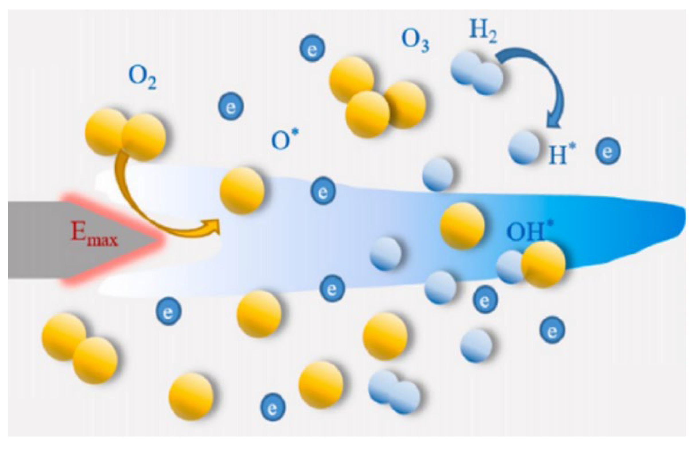
The core workflow operates as follows: Purified water from the storage module undergoes electrolysis, splitting it into hydrogen and oxygen. These gases are then delivered to the combustion chamber through dedicated gas supply lines; hydrogen is directly injected into the combustion chamber, while oxygen is supplied to the microwave ignition module. The module combines a solid-state microwave source with an igniter, using the microwave field to excite oxygen molecules and produce a high-energy plasma torch. This plasma serves as a stable ignition source for hydrogen in the combustion chamber. Upon ignition, the hydrogen–oxygen mixture undergoes vigorous combustion, generating a high-temperature, high-pressure gas. This gas is then accelerated through a converging–diverging nozzle to produce directional thrust.
Figure 1. Experimental system diagram of microwave ignition water electrolysis propulsion system.
Sustainability 17 05549 g001
The system operation process is as follows:
(1)
The electrolyzer is energized and maintained under constant operating conditions until steady-state performance is achieved.
(2)
The hydrogen supply line isolation valve is actuated to initiate hydrogen injection into both the delivery piping network and combustion chamber.
(3)
The oxygen manifold control valve is engaged to charge the plasma igniter assembly with high-purity oxygen.
(4)
A microwave-excited solid-state plasma generator is activated to establish a stable thermal plasma torch within the ignition cavity.
(5)
Diagnostic instrumentation, including high-speed imaging systems and data acquisition modules, records transient process characteristics and operational parameters throughout the test sequence.

2.1. Homemade Propellers

The thruster’s core component is a quarter-wavelength coaxial resonant cavity (QWCRC). The cavity structure is carefully designed with precise geometrical parameters to support pure transverse electromagnetic (TEM) wave propagation, effectively suppressing higher-order mode interference. Its dimensions are optimized to maximize power handling capacity, approaching the theoretical limit. The resonant cavity incorporates a bottom-mounted compact igniter with a threaded interface, minimizing insertion loss between the microwave pins and the cavity. Surface impedance matching at the contact interface boosts microwave energy transmission efficiency beyond 92%.
The resonant cavity incorporates a multi-stage flow optimization system, featuring a topology-optimized skeletal inlet chamber at its center. A gradually tapered-expanding flow channel configuration reduces and stabilizes the working gas velocity from an initial 25 m/s to 5 ± 0.3 m/s. This configuration yields a laminar flow fraction exceeding 85% throughout the homogeneous flow field within the chamber. The combustion chamber features symmetric Φ2.0 mm air inlets on both sidewalls. Computational fluid dynamics (CFD) simulations demonstrate that this configuration achieves complete turbulent mixing of the C2H4/O2 mixture within 20 ms, with a mixing uniformity index of 0.93, significantly enhancing combustion stability.
COMSOL Multiphysics 3D software is used to analyze the electric field inside the thruster. The version of the software is COMSOL 6.0. The computational domain is maintained at an isothermal condition of 293.15 K under 101.325 kPa.
Simulation results indicate a strong dependence of the near-field electric field distribution on the antenna head geometry. Comparative analysis reveals that a conical tip configuration exhibits superior field-enhancing characteristics due to its high curvature radius at the apex, which induces localized surface charge accumulation. This geometric singularity results in significant enhancement of the electric field intensity at the antenna tip, thereby justifying the selection of a conical profile for optimal field confinement.

2.2. Data Collection Device

As illustrated in 
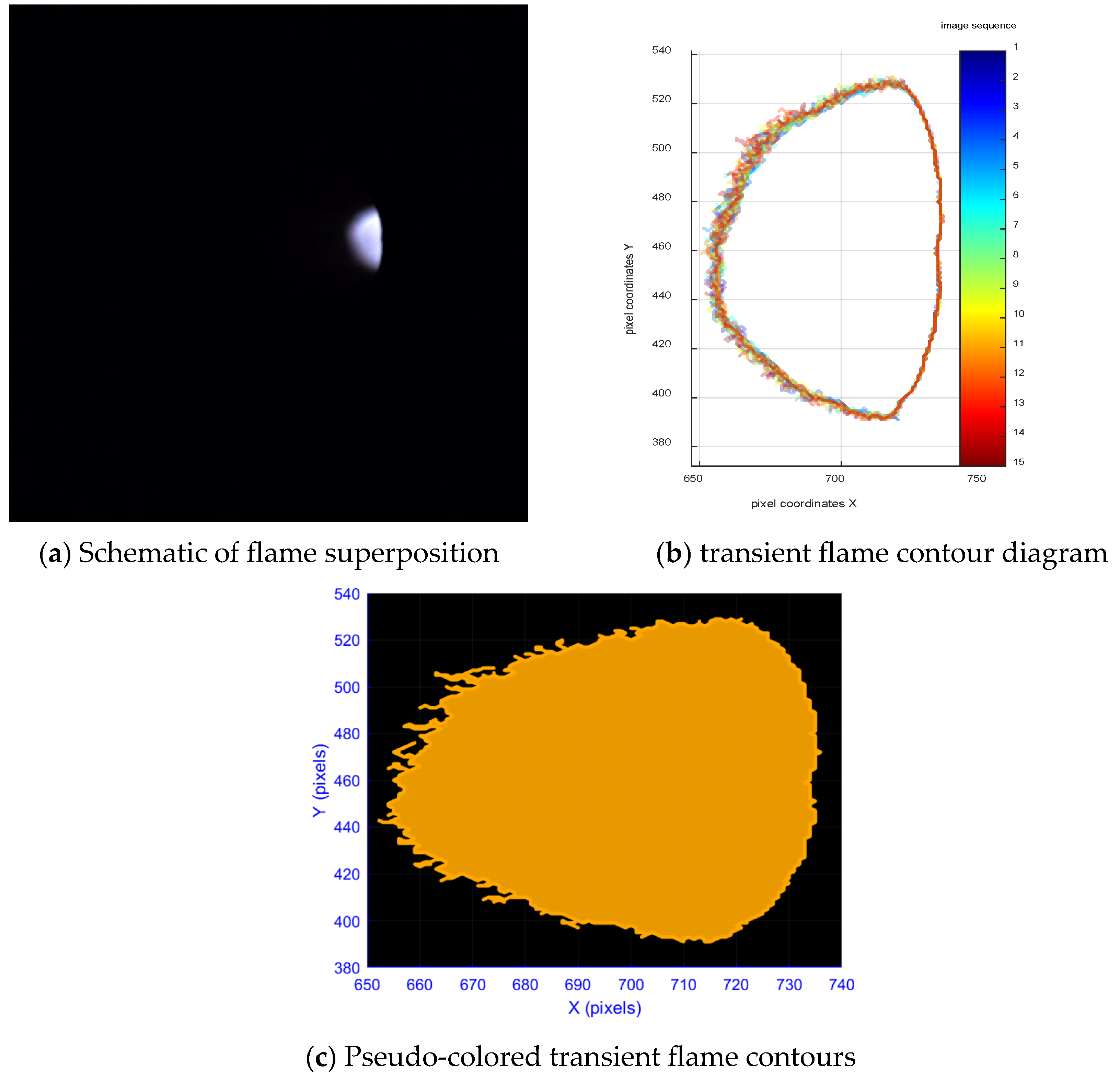
Figure 2, the whole device consists of a high-speed camera, pressure sensor, and a spectrometer. The high-speed camera records at 1000 fps to clearly capture every frame of the flame. It can be seen that the axis of the high-speed camera and the nozzle are not exactly at an angle of 90°, which is measured as θ = 71.5°. The shape of the flame observed in this way is actually a projection of the real flame, and to calculate the quantitative data, it is necessary to divide the calculated data by sin71.5°.
Flame emission spectra were acquired using an Ocean Optics USB2000+ miniature fiber-optic spectrometer, configured with a spectral range of 200–900 nm, an optical resolution of 1.5 nm (FWHM), and an integration time of 1 ms. The spectrometer was coupled to a high-temperature-resistant optical fiber probe positioned at a standoff distance of 10 cm from the ignition point to ensure minimal thermal interference while maintaining sufficient signal intensity.
Spectral data acquisition was performed in real-time using COMSOL Multiphysics 3D software, which facilitated continuous monitoring and recording of radiative emission features across the ultraviolet–visible–near-infrared (UV-Vis-NIR) spectrum. The system was calibrated for wavelength accuracy and relative intensity response prior to experimentation to ensure measurement fidelity.
Figure 2. Schematic diagram of the image and spectral acquisition system.
Sustainability 17 05549 g002
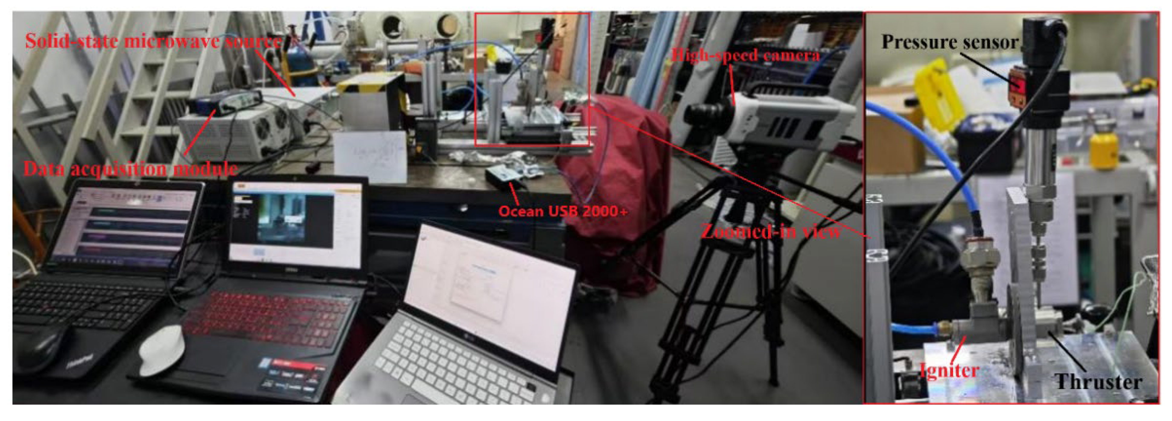
The spatial configuration of the high-speed imaging system is illustrated in Figure 3. The experimental apparatus was instrumented with three high-precision piezoresistive pressure transducers (accuracy: ±0.5% FS, sampling frequency: 10 Hz, full-scale range: 0–50 SLM, maximum pressure rating: 3 MPa) for simultaneous pressure monitoring of the hydrogen supply manifold, the oxygen delivery line, and the combustion chamber volume.
Through real-time pressure differential measurements across the gas transmission conduits, instantaneous mass flow rates were derived using the isentropic flow equations. The experimental investigations were conducted using a microwave electrothermal propulsion test bench, with the microwave excitation system operating at a constant output power of 300 W (2.45 GHz).
Figure 3. The actual ignition platform and observation system.
Sustainability 17 05549 g003
The specific parameters of the experimental apparatus used above are as follows: Ocran USB 2000+ miniature fiber-optic spectrometer for the experiment, fiber-optic probe of about 10 cm from the ignition point, 200–900 nm maximum spectrometer measurement range with a resolution of 1.5 nm, and a 1 ms detection integration interval.

3. Results and Discussion

3.1. Overview of the Complete Operation of the Thruster

As shown in Figure 4, during ignition, the inner flame region exhibits progressive expansion in both area and luminosity. This region is characterized by a dominant white coloration with a small, bright core. In contrast, the outer flame region remains comparatively limited in spatial extent, displaying irregular boundaries and intermittent flickering or pulsation behavior.
During the stabilized combustion regime, the flame exhibits a dual-zone structure with distinct morphological evolution:
(1)
The primary reaction zone demonstrates moderate spatial expansion, with its projected area increasing by approximately 20–30% relative to the ignition phase.
(2)
The secondary reaction zone undergoes significant spatial development, achieving approximately double radial expansion relative to the initial flame dimensions, with pronounced axial elongation along the reactant jet trajectory.
Spectroscopic observations reveal strong blackbody continuum emission in the inner zone vicinity (λ ≈ 400–700 nm), indicating high-temperature soot formation, while the flame periphery exhibits characteristic CH*/C2* chemiluminescence (λ ≈ 431 nm and 516 nm, respectively), consistent with complete combustion conditions. The flame tip displays a well-defined azure coloration, corresponding to excited-state molecular band emission from intermediate radical species.
During flame recession, both the luminous area and radiant intensity progressively diminish until complete extinction occurs at the flame tip. The flame core undergoes progressive contraction accompanied by rapid luminosity decay, while the outer flame fragments into discrete remnants before complete extinction occurs.
The observed dark red residual glow corresponds to thermal radiation from unburned particulates at temperatures below 1000 K, exhibiting spectral characteristics analogous to afterburning phenomena.
While the experimental imaging results remain somewhat limited in clarity, key features remain discernible. To enhance interpretability, we have supplemented the original images with annotated markers highlighting critical regions. Future work will incorporate optimized high-speed camera focusing to improve image resolution.
Figure 4. Flame image of the complete work process at the thruster nozzle.
Sustainability 17 05549 g004

3.2. Data Results

This section introduces the combustion condition of propellant fuel at different pressures. By observing the pressure change graph of the combustion process, three peak points of pressure are found. This experiment belongs to the ultra-thin combustion operating condition. Total ignition time is 149 s. Under the pulsed working condition of the thruster, the combustion data is shown in Figure 5.
Figure 5. Plot of different working condition points.
Sustainability 17 05549 g005

3.2.1. Oxygen Pressure of 22.09 kPa (Case 1)

The first pulse point occurs when the oxygen pressure is 22.09 kPa (Case 1). The terminal hydrogen pulse pressure at this point is 0.57 kPa. The terminal pulse pressure of the system remains relatively constant, as shown in Figure 6a. Figure 6b shows the combustion pressure in the combustion chamber; the average combustion pressure measured is 6.84 kPa based on the pressure sensor data. The generated pressure data is shown in Figure 6c, which shows that the data is in the neighborhood of 0.38 Newtons.
Figure 6. Intake pressure, combustion pressure, and generated thrust for Case 1.
Sustainability 17 05549 g006
Figure 7a shows a superimposed image of the nozzle flame under the current operating conditions. Image superposition produces a dominant blue-violet hue in the captured sequences, consistent with combined spectral emissions from the combustion process. Figure 7b presents the temporal evolution of the flame boundary under these conditions. The right scale bar indicates successive flame positions at 0.01 s intervals, with the initial contour corresponding precisely to the pulse initiation. Semi-transparent rendering accommodates the high temporal resolution (100 contours per second). Figure 7c presents a pseudo-color representation of flame morphology. Quantitative analysis yields a flame length of 6.64 mm and an enclosed area of 63.51 mm2, as determined from the flame boundary profile.
Figure 7. Flame information for Case 1.
Sustainability 17 05549 g007

3.2.2. Oxygen Pressure of 35.20 kPa (Case 2)

The oxygen pressure at the next pulse point is 35.20 kPa. The terminal hydrogen pulse pressure at this point is 1.04 kPa. Figure 8 shows the terminal pulse pressure and the combustion pressure in the combustion chamber. The terminal pulse pressure of the system is relatively stable. Based on pressure sensor measurements, the average combustion pressure is measured to be 3.71 kPa. The pressure data generated is shown in Figure 8c, which shows that the data varies around 0.37 Newtons.
Figure 8. Intake pressure, combustion pressure, and generated thrust for Case 2.
Sustainability 17 05549 g008aSustainability 17 05549 g008b
Figure 9a depicts a schematic of flame superposition under current operating conditions. Compared to Case 1, the overall brightness of the flame has increased, and it can be seen that the color of the flame has become whitish. Analysis suggests that the flame superposition image will develop bright white luminosity in later stages. Figure 9b displays the corresponding flame boundary progression, while Figure 9c presents pseudo-color thermal mapping. Quantitative evaluation reveals a flame length of 6.33 mm and an enclosed projection area of 65.31 mm2, derived from boundary profile analysis.
Figure 9. Flame information for Case 2.
Sustainability 17 05549 g009aSustainability 17 05549 g009b

3.2.3. Hydrogen Pressure of 5.81 kPa (Case 3)

The experimental measurements reveal a terminal hydrogen pulse pressure of 5.81 kPa, while the oxygen feed system maintains a steady terminal hydrogen pulse pressure of 1.35 kPa throughout operation. As shown in Figure 10, the pressure profiles exhibit stable propellant feed conditions with periodic combustion-induced fluctuations. Time-averaged analysis yields a mean chamber pressure of 4.64 kPa, corresponding to a thrust output of 0.35 N, as derived from chamber pressure integration.
As shown in Figure 11a, a distinct flame can be observed under the present operating conditions. The outer regions of the flame are distinctly white. The observed color transition results from spectral superposition during peak combustion, where the characteristic blue emission combines with broader thermal radiation to produce a bright white luminosity. Figure 11b presents the flame boundary profile under these operating conditions, while Figure 11c displays the corresponding pseudo-color thermal mapping. Quantitative analysis yields a flame length of 6.54 mm and an enclosed area of 68.67 mm2 derived from the contour integration.
Under these conditions, the flame morphology is clearly visible. The right side exhibits a semi-elliptical profile due to the acute angle between the high-speed camera and the nozzle axis, while the left side displays an outwardly diverging structure.
Figure 11. Flame information for Case 3.
Sustainability 17 05549 g011aSustainability 17 05549 g011b

3.3. Combustion Spectral Analysis of Thruster Exhaust Gases

Optical emission spectroscopy was employed to characterize the radiant properties of the nozzle-ejected combustion plume across varying chamber pressures (Figure 12). The acquired spectra exhibited continuum radiation characteristics typical of high-temperature combustion products, with distinct atomic emission lines superimposed on the thermal background. Spectral line identification was performed through comparative analysis with the NIST Atomic Spectra Database [23], revealing characteristic atomic transitions at
(1)
410.17 nm (Hδ, n = 6→2) and 486.13 nm (Hβ, n = 4→2), corresponding to hydrogen Balmer series emissions;
(2)
777.19 nm (O I 3p5P→3s5S0), indicating atomic oxygen presence;
(3)
818.48 nm (N I 3s4P→3p4P0), denoting atmospheric nitrogen entrainment.
Figure 12. Spectrograms for three operating conditions.
Sustainability 17 05549 g012aSustainability 17 05549 g012b
The emission spectra obtained in this study exhibit distinct atomic absorption features at 410 nm and 486 nm (Hα and Hβ Balmer series transitions) along with prominent emission peaks at 798 nm (O I 3p5P→3s5S0) and 818 nm (N I 3s4P→3p4P0). These spectral signatures confirm the presence of atomic hydrogen, oxygen, and nitrogen in the combustion products. The observed intensity inversion between oxygen emission peaks and hydrogen absorption valleys reflects the stoichiometric imbalance of the propellant mixture, where the oxygen-rich combustion environment (equivalence ratio Φ < 1) enhances oxygen excitation while suppressing hydrogen emission.
The detection of atmospheric nitrogen spectral lines (N I 818.48 nm) originates from ambient air entrainment (78% N2 composition) into the exhaust plume. Figure 13 presents the plasma-assisted combustion mechanism:
(1)
Microwave irradiation (2.45 GHz) establishes a standing wave pattern in the resonant cavity, generating a localized high-intensity electric field (E > 30 kV/m) at the antenna tip. Particles are excited under the action of an electric field, and the particles in the excited state have * as the superscript;
(2)
Dielectric breakdown ionizes oxygen molecules (O2 + e → O+ + O + 2e), forming a low-temperature plasma torch (T ≈ 4000 K);
(3)
This plasma kernel initiates chain-branching reactions with hydrogen fuel in the combustion chamber.
The spectral confirmation of atomic oxygen lines validates the plasma-mediated ionization process, consistent with prior microwave plasma propulsion studies [24,25].
Figure 13. Ionization mechanism inside the thruster.
Sustainability 17 05549 g013

3.4. Horizontal Comparison Under Different Conditions

The hydrogen and oxygen pressures in different cases are illustrated in Figure 14. At the first oxygen pressure pulse point, the oxygen pressure is 22 kPa and the hydrogen pressure is 0.57 kPa, and at the second pressure pulse point, the oxygen pressure is 35 kPa and the hydrogen pressure is 1.0 kPa. Compared to the first condition point, the oxygen pressure increases by 59.1% and the hydrogen pressure by 75.4%. At the hydrogen pressure pulse point, the oxygen pressure drops to 1.3 kPa (−94.1%), while the hydrogen pressure surges to 5.8 kPa (+917.5%).
Figure 14. Comparison of hydrogen and oxygen pressures under three pulse conditions.
Sustainability 17 05549 g014
Figure 15 quantifies flame areas as 63.51 mm2 (Case 1), 65.31 mm2 (Case 2), and 68.67 mm2 (Case 3). Relative to Case 1, Case 2 exhibits a 2.8% increase in flame area, while Case 3 shows a 5.1% increase over Case 2. This progression demonstrates not only gradual expansion of the flame area but also an accelerating growth rate, indicating progressively intensifying combustion behavior.
Figure 15. Comparative analysis of flame area evolution across three pulse conditions.
Sustainability 17 05549 g015
Figure 16 shows the combustion pressure curve of the combustion process. The combustion pressure ranges from 3.5 to 4.6 kPa, with an average pressure of 4.05 kPa. The pressure rises at a relatively fast rate and decays relatively gently, and it is speculated that the reason for the fluctuation may be due to the formation of plasma by microwave ignition, which can act as the active center for promoting the combustion reaction. However, the formation and diffusion of plasma are dynamic processes, and the microwave energy form is also fluctuating.
Figure 16. Combustion pressure change curve of direct microwave ignition.
Sustainability 17 05549 g016
Figure 17 shows the generated thrust visualization curve. After the second condition point, the thrust fluctuation is more obvious, from the average pressure of 0.375 N to 0.6 N, then suddenly dropping to 0.125 N and finally returning to the stable stage, where the average pressure is 0.3 N. After the hydrogen pressure pulse at point 2 s, there is a thrust peak, with a maximum thrust of 2.25 N. The reason for the first thrust fluctuation is because at the second condition point, there is a hydrogen pressure increase, so more hydrogen can be ignited and more thrust is provided. After that, the stabilization stage is 0.3 N lower than 0.375 N because the hydrogen pressure at the 0.3 N time period is less than the hydrogen pressure at the 0.375 N time period. The reason for generating the maximum thrust is that, at this time, there is maximum consumption of hydrogen, which produces more thrust, and it is concluded that by letting the hydrogen pulse more, more thrust will be gained.
Figure 17. Thrust during the whole process of direct microwave ignition change curve.
Sustainability 17 05549 g017

4. Conclusions

Water electrolysis microwave ignition technology provides a disruptive solution for propulsion systems. Compared with the traditional catalytic ignition method, this technology generates plasma jets through direct microwave ionization of mixed gases, which not only eliminates the degradation-prone catalytic bed structure and preheating process, but also significantly improves the ignition reliability and combustion efficiency through highly active particles. Experiments have confirmed that the microwave ionization process can effectively excite hydrogen/oxygen atoms to higher energy states, and this non-equilibrium activation mechanism significantly broadens the flammability limit, while meeting the system’s requirements for lightweight, long-life, and green propulsion.
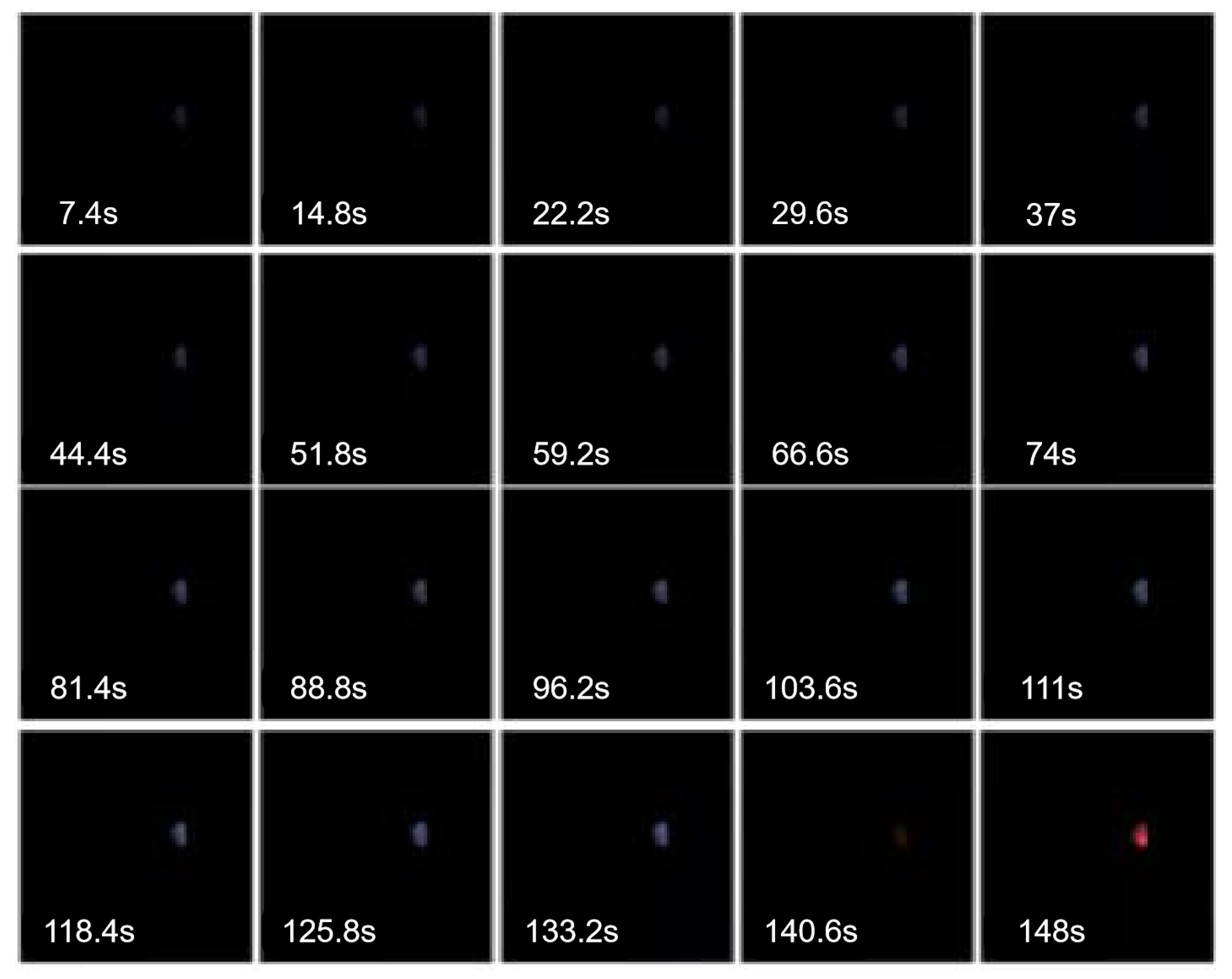
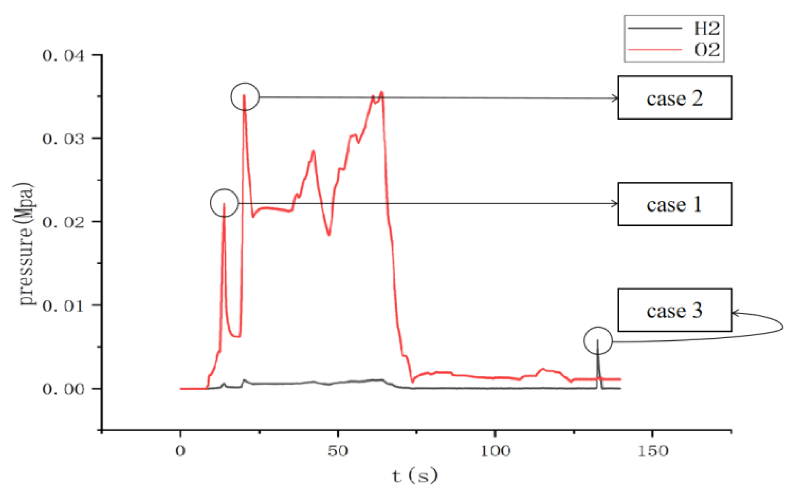
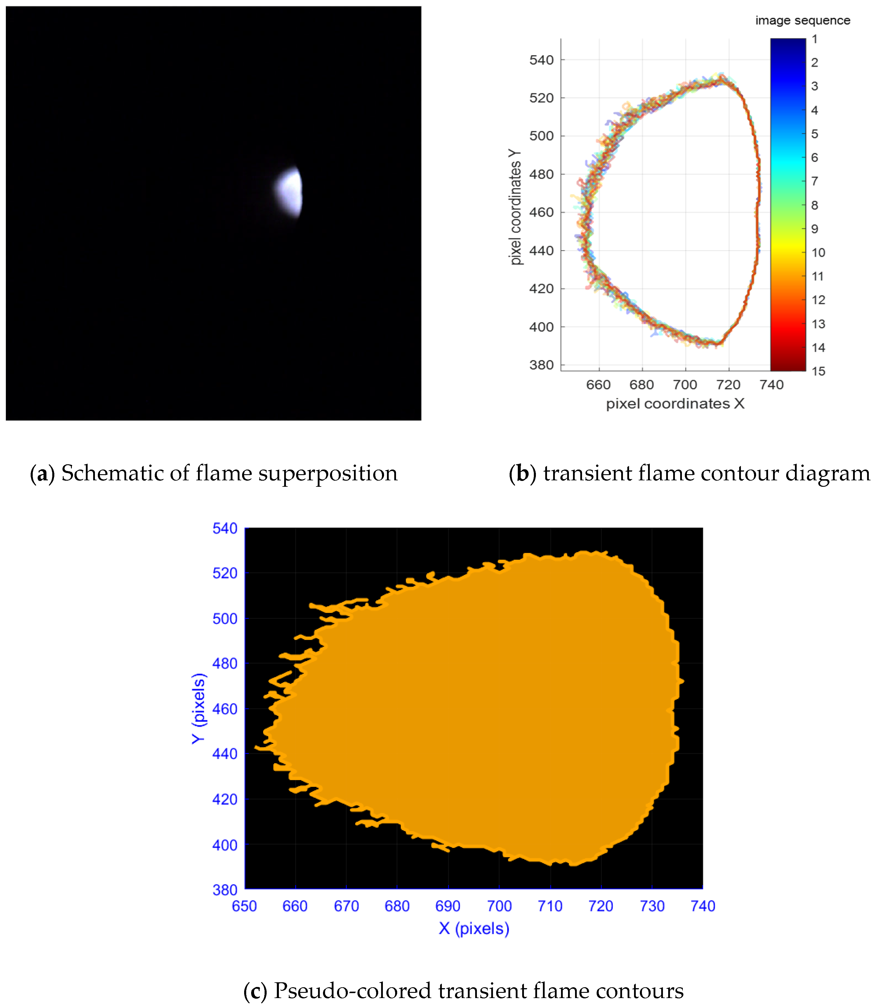
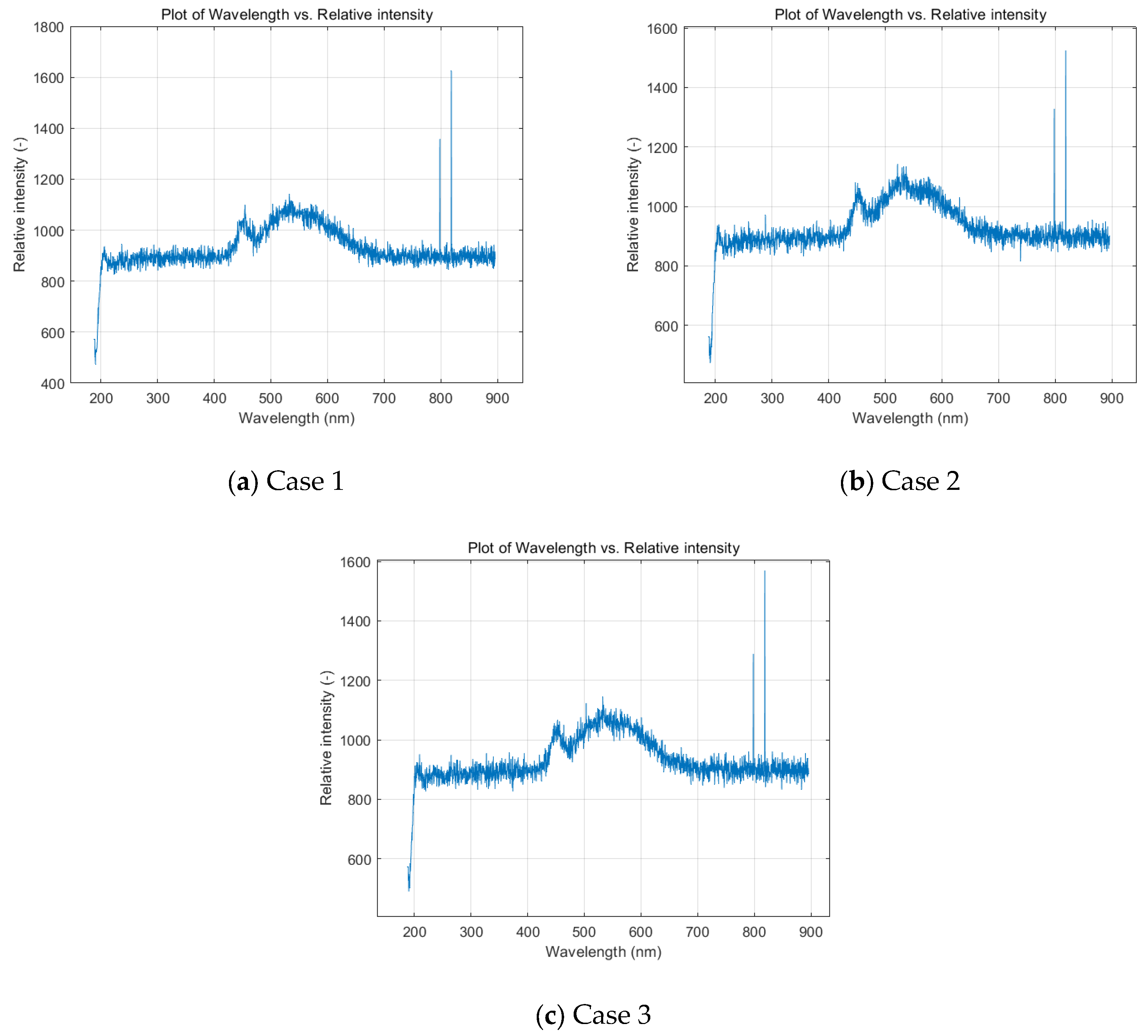
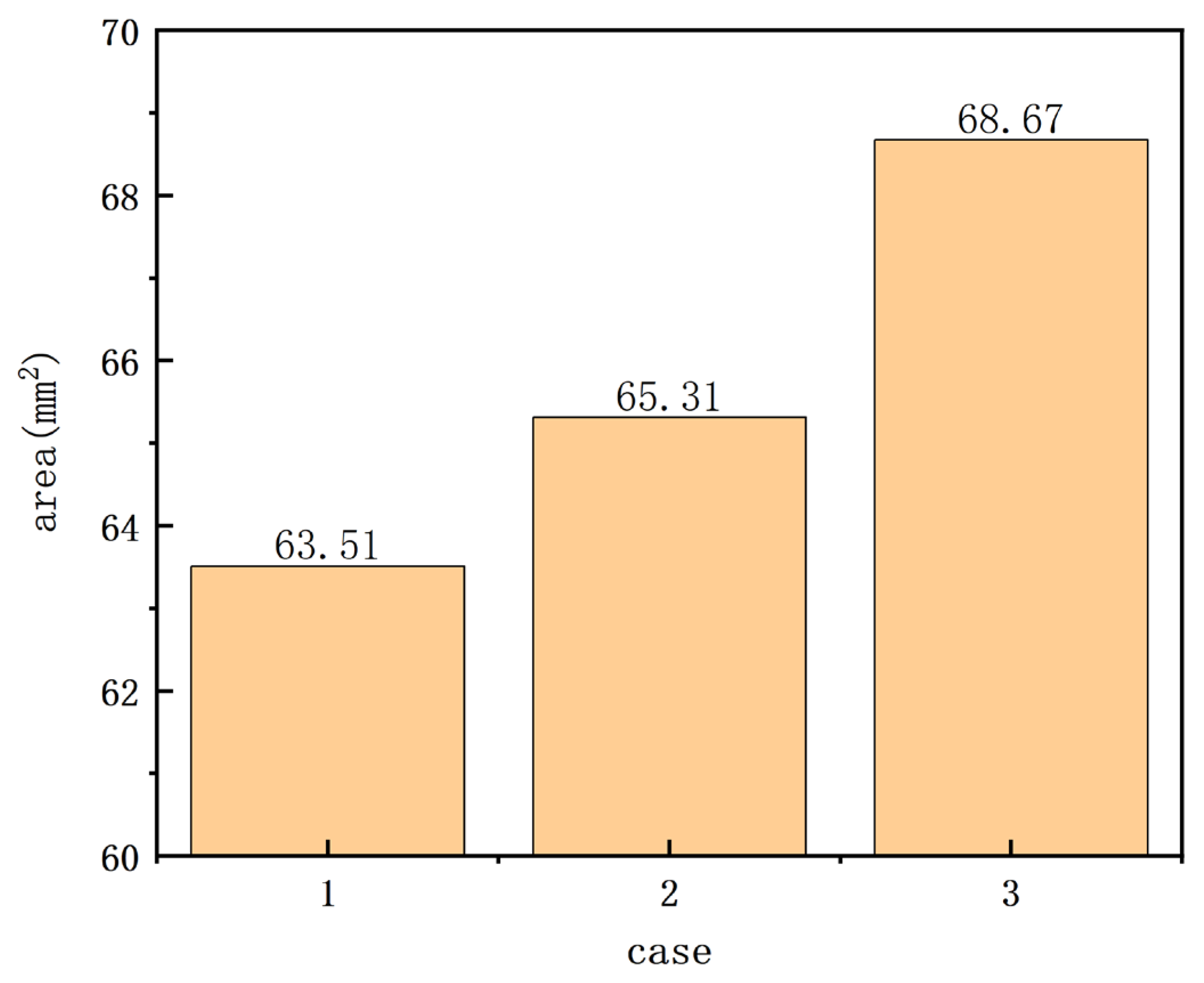
As time progresses, the brightness of both the internal and external regions of the flame increases, with the internal region of the flame showing a bright white color and the external region of the flame having traces of blue color. The combustion pressure was enhanced by 25% from Case 2 to Case 3, and the maximum thrust produced was increased by 508% compared to Case 2. Although the spectral intensity of the three conditions changed, the change rule of spectral intensity with wavelength was consistent.
In this study, we experimentally investigated the pulse operating characteristics of the water electrolysis chemical propulsion engine based on microwave ignition technology and verified the technological advantages of this propulsion system in terms of fast response, controlled combustion, and clean products. From the perspective of sustainability, water electrolysis propulsion technology takes water as the reaction medium, and its combustion products are only hydrogen, oxygen atoms, and trace nitrogen components, which completely avoids the emission of carbon-containing pollutants or greenhouse gases from traditional chemical propellants and is in line with the development trend of aerospace greening. The efficient energy utilization of microwave ignition technology further reduces the energy consumption of the system, and the renewable characteristics of water resources make this technology have the potential of closed-loop application. In the future, the combination of renewable power systems and material cycle design could build a whole-life low-carbon chain from energy input to propellant preparation, providing a power solution for small spacecraft that meets sustainable development goals. Subsequent research should focus on optimizing the system’s energy efficiency ratio and resource utilization in order to enhance its environmentally friendly characteristics in space missions.

Author Contributions

Conceptualization, Z.X. and Z.W.; methodology, Y.Y.; validation, S.W.; resources, Y.Y.; writing—original draft preparation, Z.X.; writing—review and editing, Z.X.; supervision, Y.Y. All authors have read and agreed to the published version of the manuscript.

Funding

Project Experimental Study on the Pulsed Operating Characteristics of a Hydrogen-Oxygen Engine Based on Microwave Ignition Technology supported by National Training Program of Innovation and Entrepreneurship for Undergraduates, No.202510004170. Beijing Engineering Research Center of Efficient and Green Aerospace Propulsion Technology and Advanced Space Propulsion Laboratory of BICE, No: LabASP-2023-08.

Institutional Review Board Statement

Not applicable.

Informed Consent Statement

Not applicable.

Data Availability Statement

Data is contained within the article.

Conflicts of Interest

The authors declare no conflicts of interest.

References

  1. Haeseler, D.; Haidinger, F.; Brummer, L.; Haberle, J.; Luger, P. Development and testing status of the Vinci thrust chamber. In Proceedings of the 48th AIAA/ASME/SAE/ASEE Joint Propulsion Conference & Exhibit, Atlanta, GA, USA, 30 July–1 August 2012. [Google Scholar]
  2. Hurlbert, E.A.; Moreland, R.J.; Candel, S. Propellant Ignition and Flame Propagation; AIAA: Reston, VA, USA, 2004. [Google Scholar]
  3. Starikovskaia, S.M. Plasma-assisted ignition and combustion: Nanosecond discharges and development of kinetic mechanisms. J. Phys. D Appl. Phys. 2014, 47, 353001. [Google Scholar] [CrossRef]
  4. Woodward, R.D. Primary Atomization of Liquid Jets Issuing From Rocket Engine Coaxial Injectors. Ph.D. Thesis, The Pennsylvania State University, University Park, PA, USA, 1993. [Google Scholar]
  5. Khan, M.F.; Quadri, Z.A.; Kulkarni, P.S.; Guven, U.; Bhat, S.P.; Sundarraj, K. CFD simulation of a liquid rocket propellant (LH2\LOx) combustion chamber. In Proceedings of the 15th Annual CFD Symposium, Indian Institute of Science, Bangalore, India, 9–10 August 2013. [Google Scholar]
  6. Filimonova, E.A.; Dobrovolskaya, A.S.; Bocharov, A.N.; Bityurin, V.A.; Naidis, G.V. Formation of combustion wave in lean propane-air mixture with a non-uniform chemical reactivity initiated by nanosecond streamer discharges in the HCCI engine. Combust. Flame 2020, 215, 401–416. [Google Scholar] [CrossRef]
  7. Bogdanov, S.; Gorbachev, A.; Vikharev, A.; Radishev, D.; Lobaev, M. Study of microwave discharge at high power density conditions in diamond chemical vapor deposition reactor by optical emission spectroscopy. Diam. Relat. Mater. 2019, 97, 107407. [Google Scholar] [CrossRef]
  8. Assadi, A.A.; Loganathan, S.; Tri, P.N.; Ghaida, S.G.-A.; Bouzaza, A.; Tuan, A.N.; Wolbert, D. Pilot scale degradation of mono and multi volatile organic compounds by surface discharge plasma/TiO2 reactor: Investigation of competition and synergism. J. Hazard. Mater. 2018, 357, 305–313. [Google Scholar] [CrossRef]
  9. Bechane, Y.; Fiorina, B. Numerical investigations of turbulent premixed flame ignition by a series of Nanosecond Repetitively Pulsed discharges. Proc. Combust. Inst. 2021, 38, 6575–6582. [Google Scholar] [CrossRef]
  10. He, W.; Sun, C.; Zhang, Z.; Zhao, H.; Yang, B. Study on the influence of hydrogen injector flow rate in hydrogen-oxygen engine thrust chamber. J. Phys. Conf. Ser. 2024, 2820, 012086. [Google Scholar] [CrossRef]
  11. Oschwald, M.; Schik, A. Supercritical nitrogen free jet investigated by spontaneous Raman scattering. Exp. Fluids 1999, 27, 497–506. [Google Scholar] [CrossRef]
  12. Stevens, C.A.; Pertl, F.A.; Hoke, J.L.; Schauer, F.R.; Smith, J.E. Comparative testing of a novel microwave ignition source, the quarter wave coaxial cavity igniter. Proc. Inst. Mech. Eng. Part D J. Automob. Eng. 2011, 225, 1633–1640. [Google Scholar] [CrossRef]
  13. Zhongli, W.; Yaoyao, W.; Liang, Z.; Yunying, T.; Wendong, M.; Jiafang, S. A Simulation Study on Plasma Discharge of Microwave Spark Plug. In Proceedings of the 2018 11th UK-Europe-China Workshop on Millimeter Waves and Terahertz Technologies (UCMMT), HangZhou, China, 5–7 September 2018; pp. 1–3. [Google Scholar]
  14. Wang, Z.; Huang, J.; Wang, Q.; Hou, L.; Zhang, G. Experimental study of microwave resonance plasma ignition of methane–air mixture in a constant volume cylinder. Combust. Flame 2015, 162, 2561–2568. [Google Scholar] [CrossRef]
  15. Wolk, B.; DeFilippo, A.; Chen, J.Y.; Dibble, R.; Nishiyama, A.; Ikeda, Y. Enhancement of flame development by microwave-assisted spark ignition in constant volume combustion chamber. Combust. Flame 2013, 160, 1225–1234. [Google Scholar] [CrossRef]
  16. Cheng, J.; Zhang, Z.; Li, F.; Ouyang, K.; Xu, J.; Ye, Y.; Shen, R. Microwave ignition characteristics and distinction of typical nanothermites under different electromagnetic radiation. Combust. Flame 2024, 260, 113217. [Google Scholar] [CrossRef]
  17. Kumari, S.; Dalal, J.; Kumar, A.; Pal, R.; Chahal, R.; Ohlan, A. Enhanced microwave absorption properties of conducting polymer@graphene composite to counteract electromagnetic radiation pollution: Green EMI shielding. RSC Adv. 2024, 14, 662–676. [Google Scholar] [CrossRef] [PubMed]
  18. Hwang, J.; Bae, C.; Park, J.; Choe, W.; Cha, J.; Woo, S. Microwave-assisted plasma ignition in a constant volume combustion chamber. Combust. Flame 2016, 167, 86–96. [Google Scholar] [CrossRef]
  19. Zhang, X.; Wang, Z.; Zhou, D.; Wu, H.; Cheng, X.; Jin, B.; Chen, J.-Y. Strengthening effect of microwave on spark ignited spherical expanding flames of methane-air mixture. Energy Convers. Manag. 2020, 224, 113368. [Google Scholar] [CrossRef]
  20. Zhang, X.H.; Wang, Z.W.; Wu, H.M. Energy deposition and plasma propulsion during the time window of microwave-assisted CH4-O2 spark ignition with Ar/N2/CO2 dilution. Combust. Flame 2022, 246, 112424. [Google Scholar] [CrossRef]
  21. Wu, H.; Wang, Z.; Cheng, X.; Huang, Y.; Chen, J.-Y.; Liu, C.; Wang, Z.; Xu, J.; Zhang, X. Effect of microwave pulse parameters on energy coupling and enhancement of microwave assisted ignition. Proc. Combust. Inst. 2023, 39, 553l–5539. [Google Scholar] [CrossRef]
  22. DeFilippo, A.; Saxena, S.; Rapp, V.; Dibble, R.; Chen, J.-Y.; Nishiyama, A.; Ikeda, Y. Extending the Lean Stability Limits of Gasoline Using a Microwave-Assisted SAE Technical Paper 2011-01-0663. Available online: https://www.sae.org/publications/technical-papers/content/2011-01-0663/ (accessed on 3 April 2025).
  23. Available online: https://physics.nist.gov/PhysRefData/ASD/lines_form.html (accessed on 3 April 2025).
  24. Sun, X.; Bao, J.; Li, K.; Argyle, M.D.; Tan, G.; Adidharma, H.; Zhang, K.; Fan, M.; Ning, P. Advance in using plasma technology for modification or fabrication of carbon-based materials and their applications in environmental, material, and energy fields. Adv. Funct. Mater. 2021, 31, 2006287. [Google Scholar] [CrossRef]
  25. Dias, T.C.; Fromentin, C.; Alves, L.L.; Tejero-Del-Caz, A.; Silva, T.; Guerra, V. A reaction mechanism for oxygen plasmas. Plasma Sources Sci. Technol. 2023, 32, 84003. [Google Scholar] [CrossRef]
Figure 10. Intake pressure, combustion pressure, and generated thrust for Case 3.
Sustainability 17 05549 g010aSustainability 17 05549 g010b
Disclaimer/Publisher’s Note: The statements, opinions and data contained in all publications are solely those of the individual author(s) and contributor(s) and not of MDPI and/or the editor(s). MDPI and/or the editor(s) disclaim responsibility for any injury to people or property resulting from any ideas, methods, instructions or products referred to in the content.

