1. Introduction
With the intensification of global energy consumption, the challenges of fossil fuel shortages and environmental pollution have become increasingly prominent [
1,
2]. To tackle this crisis, nations globally are expediting energy transitions by advancing renewable and clean energy development [
3,
4]. Among these, wind power generation, with its advantages of cleanliness, abundant resources, and technological maturity, has rapidly gained traction and become a core component of renewable energy systems [
5,
6]. However, as the share of wind power in the energy grid continues to rise, its inherent output volatility and intermittency pose significant challenges to the stable operation of power grids [
7,
8,
9]. Against this backdrop, pumped storage units, with their flexible regulation capabilities and advanced energy storage technology, have emerged as a critical solution for mitigating the fluctuations of renewable energy [
10,
11,
12]. By flexibly switching between energy storage and generation modes, pumped storage effectively enhances the grid adaptability to renewable energy sources, thereby improving its capacity to accommodate a high penetration of renewable energy [
13,
14,
15].
The current mainstream wind power systems predominantly employ doubly fed induction generators (DFIGs) [
16,
17], which offer advantages such as low manufacturing costs, high wind energy utilization efficiency, and enhanced reliability [
18]. DFIGs achieve precise control of active and reactive power through back-to-back converters [
19], enabling dynamic response capabilities across the sub-synchronous to super-synchronous frequency range. In contrast, pumped storage units with synchronous machines focus on low-frequency regulation due to mechanical–hydraulic inertia. The wide-bandwidth response of wind turbines and narrow-bandwidth regulation of pumped storage complement each other but also increase the risk of complex oscillations in hybrid systems. For instance, when DFIG-based wind turbines are connected to the grid via series-compensated transmission lines, the interaction between converter controls and the line’s capacitive reactance may induce sub-synchronous oscillations (SSOs) [
20,
21]. Such incidents have been reported in real cases, including in Texas, USA [
22], Minnesota, USA [
23], and northwest China [
24]. Consequently, exploring the impact of synchronous pumped storage integration on the oscillatory behavior of wind-pumped hybrid systems is crucial. Developing small-signal models considering the coupling of wind power, pumped storage, and transmission systems, as well as uncovering multi-timescale dynamic interactions, is essential for the stability of high-penetration renewable energy grids.
In recent years, the oscillatory stability of DFIG-based renewable energy systems and corresponding suppression methods have become a focal point of research for experts and scholars worldwide. Vijay et al. [
25] summarized the impact of fixed-/variable-speed hydro, wind, and photovoltaic systems on SSOs. Koushal et al. [
26] studied the methods for evaluating and analyzing SSOs in wind energy systems using a DFIG and a hybrid photovoltaic/battery energy storage system in a series-compensated grid and analyzed the impact of different parameters on grid stability. Ezzeddine et al. [
27] proposed a new method that combines a resonant controller with the DFIG control loop to mitigate SSOs in series-compensated transmission lines. Xue et al. [
28] conducted an in-depth analysis of the instability mechanism of DFIGs using impedance-based stability assessment and identified the key parameters affecting resonance. Meng et al. [
29] developed a mathematical model of the DFIG system to investigate the causes of SSOs and proposed an improved phase-locked loop (PLL), addressing the performance degradation of the latter under SSOs. Zhang et al. [
30] proposed a grid-side sub-synchronous damping controller (SSDC) that uses bus voltage and line current as feedback signals. The controller injects current into the system at the sub-synchronous frequency to provide active damping, effectively mitigating SSOs under a wide range of operating conditions. Perera et al. [
31] analyzed the influence of solar and wind energy variability on the SSO frequency characteristics of parallel-connected PV and wind farms with series-compensated transmission lines. The results indicate that in DFIG-based wind farms, lower average wind speeds exacerbate SSOs, while variations in solar radiation have a negligible impact. Wang et al. [
32] investigated the impact of voltage control parameters, series compensation levels, and different power outputs on SSO behavior in hybrid wind farms composed of DFIGs and permanent magnet synchronous generators (PMSGs) and proposed a robust SSO suppression controller that effectively mitigates SSO issues.
It is worth noting that previous studies often had certain shortcomings in methods or models. They did not investigate the potential coupling between different systems, did not consider the oscillation behavior of multi-agent renewable energy systems, and did not account for the impact of synchronous machines on SSOs dominated by a DFIG under different operating modes. To address the aforementioned limitations, this paper considers a renewable energy system with a doubly fed wind farm and synchronous pumped storage, connected in parallel to a series-compensated grid. To investigate the oscillatory behavior of a complete hybrid system under grid-connected operations in both generation and pumping modes, this study adopts a modular modeling approach. The modular modeling approach decomposes complex systems into independent modules, enhancing system variability and scalability and making development, testing, and debugging more efficient and flexible. Compared to traditional methods, it offers significant advantages in handling complex systems. A comprehensive state–space model is developed, and the oscillatory characteristics of the model are analyzed, with a particular focus on the properties and influencing factors of the SSO modes. Based on relative participation analysis, this study proposes a simplified modeling method that neglects the dynamic characteristics of the synchronous machine and considers only its steady-state effects on the system. Furthermore, the study emphasizes the feasibility and effectiveness of introducing a supplementary SSDC on the rotor side of the wind turbine to mitigate SSOs. This research is crucial for analyzing the small-signal stability of hybrid systems with DFIGs and synchronous machines, offering theoretical support for oscillation analysis and suppression strategies.
The remainder of this paper is organized as follows:
Section 2 establishes the complete state–space model of the hybrid system combining wind power and pumped storage units;
Section 3 verifies the accuracy of the proposed model through time-domain simulations, performs eigenvalue analysis and relative participation analysis based on the mathematical model, investigates the impact of series compensation on oscillations, identifies the dominant state variables of each oscillation mode, and proposes a simplified modeling method accordingly;
Section 4 examines the effectiveness of adding an SSDC on the rotor side of the wind turbine to suppress SSO in the hybrid system; and finally,
Section 5 summarizes the key conclusions of this paper and discusses future research directions.
2. Mathematical Model of the Hybrid System
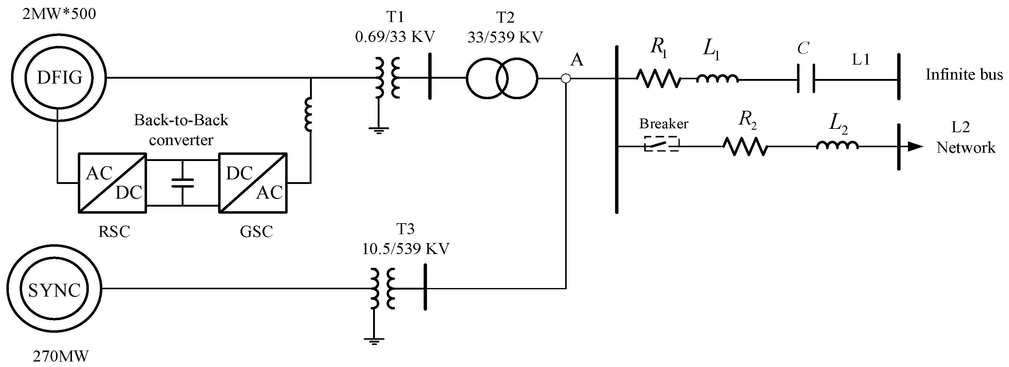
This study focuses on a hybrid system composed of DFIG-based wind turbines and a synchronous pumped storage unit, connected in parallel to an infinite bus via a series-compensated transmission line. The model includes the wind turbine’s shaft system, the DFIG with its converter control system, and the synchronous pumped storage unit consisting of a synchronous machine, an excitation system, and a PSS, as well as the series-compensated transmission line.
The SSO characteristics of the hybrid system were analyzed using a modified IEEE first benchmark model [
33]. The configuration of the hybrid system is illustrated in
Figure 1. It comprises 500 DFIG-based wind turbines, each with a rated capacity of 2 MW, which are stepped up by transformers T1 and T2. These wind turbines are paralleled at point A by a synchronous pumped storage unit rated at 270 MW, which is stepped up by transformer T3. Once the system stabilizes, at a specific time t, series compensation is achieved by disconnecting the L2 branch, simulating the system’s connection to the grid via a series-compensated transmission line. The detailed parameters are provided in
Appendix A.
2.1. Model of the DFIG-Based Wind Turbine
2.1.1. Aerodynamic and Two-Mass Shaft System Model of the Wind Turbine
The aerodynamic model calculates the mechanical torque based on the airflow impacting the blades of the variable-speed wind turbine, allowing the wind power captured by the impeller to be determined. The wind speed is assumed to be the average wind speed acting on the swept area of the blades. The mechanical power
generated by the impeller can be expressed as [
34]:
where
is the radius of the wind turbine blades,
is the pitch angle of the variable-speed wind turbine,
is the tip-speed ratio,
is the air density,
is the average wind speed, and
is the power coefficient, which characterizes the efficiency of the variable-speed wind turbine in converting kinetic energy into mechanical energy.
The two-mass model was adopted to simulate the shaft dynamics of the doubly fed wind turbine. The dynamic equations are as follows:
where
and
are the inertia time constants of the wind turbine-side mass and the rotor-side mass, respectively,
and
are the rotational speeds of the wind turbine-side mass and the rotor-side mass, respectively,
is the relative angular displacement between the two mass blocks,
and
are the shaft stiffness coefficient and damping coefficient, respectively,
and
are the mechanical torque of the wind turbine and the electromagnetic torque of the rotor, respectively, and
is the reference value of the grid angular velocity.
2.1.2. Model of the DFIG
The DFIG is composed of two sets of windings: the stator and the rotor windings. While the stator winding is directly connected to the power grid, the rotor winding interfaces with the grid through a back-to-back converter. The dynamic model of the DFIG, formulated in the
d-q rotational reference frame, is as follows:
where
where
and
are the components of the transient electromotive force along the
d-axis and
q-axis, respectively,
is the stator reactance,
is the stator transient reactance,
is the rotor circuit time constant,
is the mutual inductance,
is the stator self-inductance,
is the rotor self-inductance,
is the stator leakage inductance,
is the rotor leakage inductance,
is the stator resistance,
is the rotor resistance,
and
are the
d- and
q-axis stator terminal voltages, respectively,
and
are the
d- and
q-axis rotor terminal voltages,
and
are the
d- and
q-axis stator currents,
is the synchronous angular speed, and
is the rotor slip.
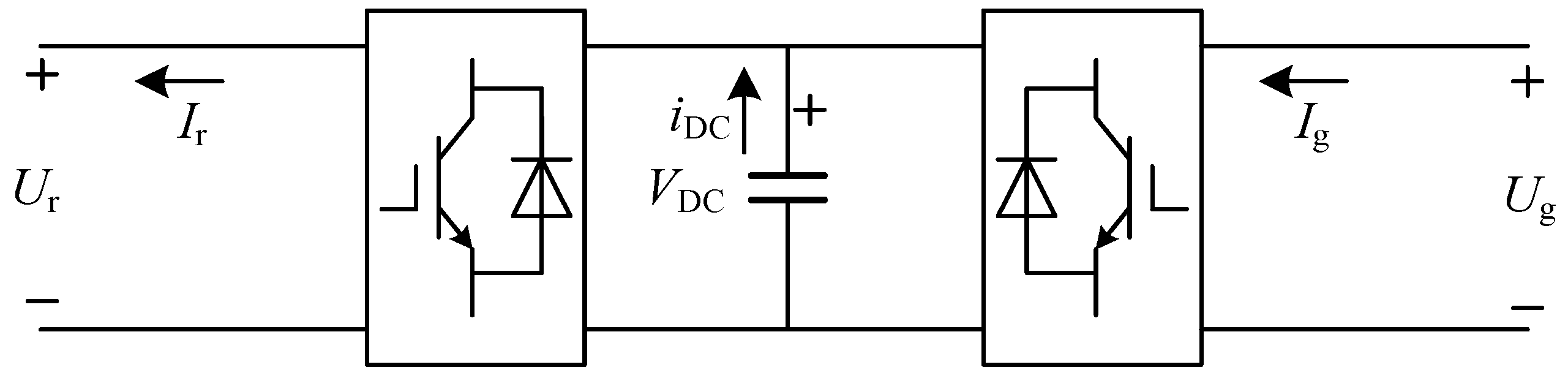
2.1.3. Model of Back-to-Back Rotor Converters
As shown in
Figure 2, the back-to-back rotor converters comprise a rotor-side converter, a grid-side converter, and a DC capacitor. The rotor-side converter excites the rotor with AC current, enabling adjustments to the rotor current frequency and phase to regulate rotor speed and power factor. The grid-side converter ensures the unity power factor and maintains the DC link voltage, balancing input and output power and ensuring reliable rotor excitation. A detailed modeling of the rotor-side converter, grid-side converter control system, and DC capacitor is included.
The model of the converters can be written as [
35]:
where
is the capacitance of the capacitor,
is the capacitor DC voltage,
is the active power at the AC terminal of the gird side converter,
and
are the
d- and
q-axis currents of the grid side converter, respectively,
and
are the
d- and
q-axis voltages of the grid side converter,
is the active power at the AC terminal of the rotor side converter, and
and
are the
d- and
q-axis currents of the rotor side converter.
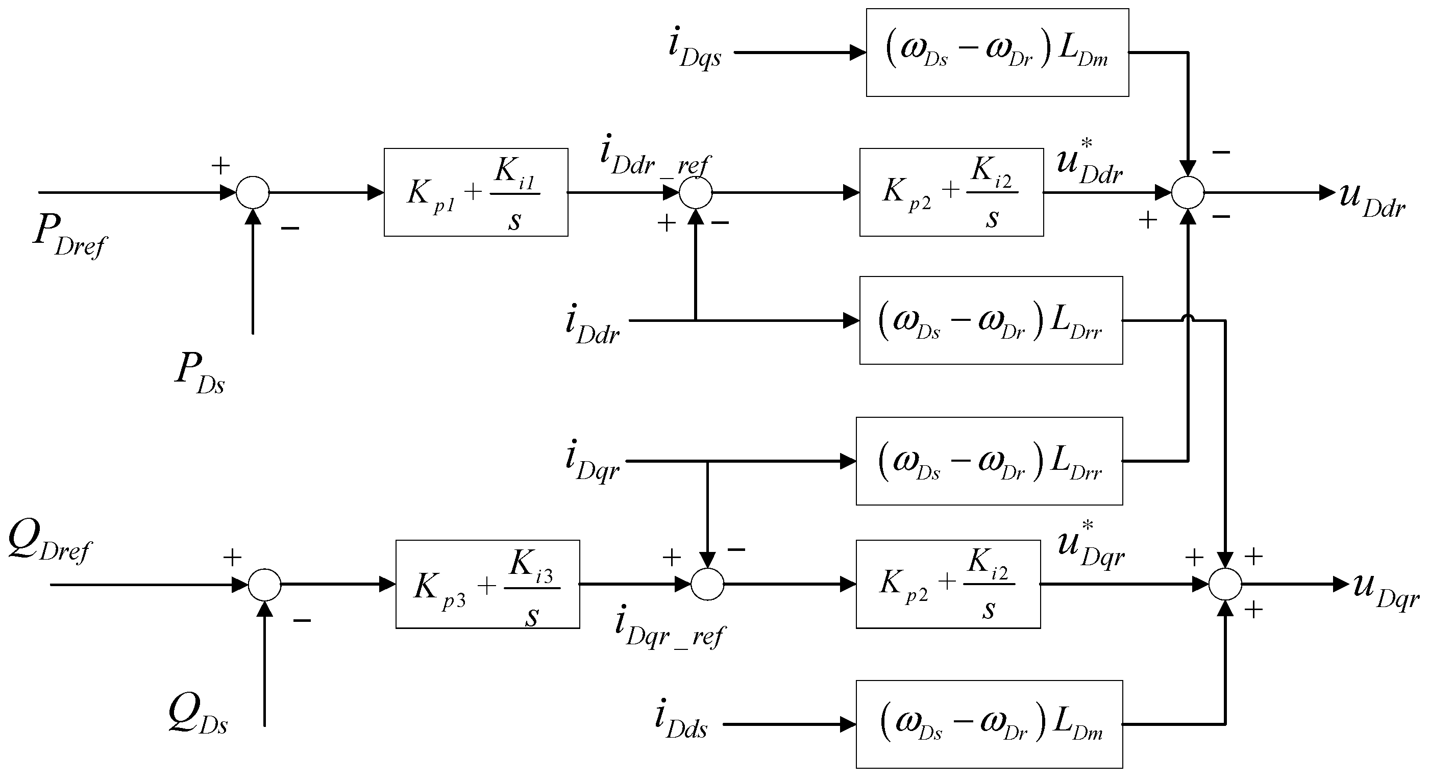
The control block diagram of the rotor side of the DFIG-based wind turbine is shown in
Figure 3.
Based on the control diagram, the controller can be modelled as [
35]:
where
,
,
,
are the intermediate variables,
and
are the proportional and integrating gains of the power regulator, respectively,
and
are the proportional and integrating gains of the rotor-side converter current regulator, respectively,
and
are the proportional and integrating gains of the grid voltage regulator, respectively,
and
are the control reference of the active and reactive power of the DFIG, and
and
are the stator active and reactive power.
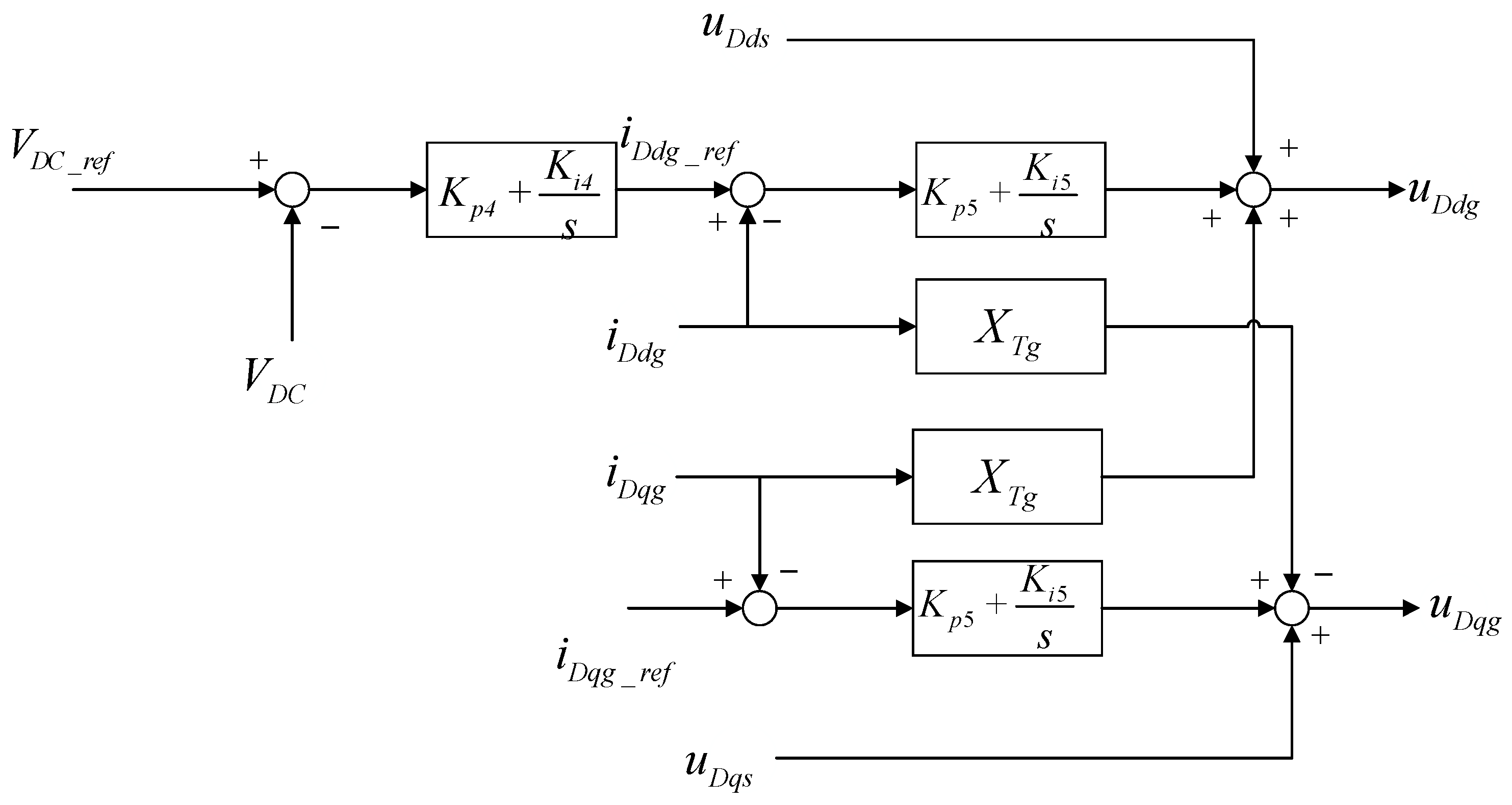
The control block diagram of the stator side of the DFIG-based wind turbine is shown in
Figure 4.
By introducing the intermediate variables
,
, and
, the model of the grid side converter can be obtained as follows:
where
and
are the proportional and integrating gains of the DC bus voltage regulator, respectively,
and
are the proportional and integrating gains of the grid-side converter current regulator,
is the voltage control reference of the DC link, and
is the reactance of the fed back transformer.
2.2. Model of the Synchronous Pumped Storage Unit
2.2.1. Model of the Synchronous Machine
For the synchronous machine, under the assumption of neglecting the stator resistance, the following relationships hold in the
d-
q-axis coordinate system:
where
and
are the stator voltage components of the synchronous machine along the
d- and
q-axis, respectively,
and
are the stator current components of the synchronous machine along the
d and
q axis, respectively,
is the synchronous reactance along the
q-axis of the synchronous machine,
is the transient reactance along the
d-axis of the synchronous machine, and
is the component of the transient electromotive force along the
q-axis of the synchronous machine.
The equation of motion for the rotor of the synchronous machine is
where
is the electrical angular position of the synchronous machine,
is the synchronous angular velocity of the system,
is the relative angular velocity of the synchronous machine,
is the input mechanical power of the synchronous machine,
is the damping coefficient of the synchronous machine,
is the moment of the inertia constant of the synchronous machine, and
is the electromagnetic power of the synchronous machine.
The differential equation of the excitation winding of the synchronous machine is
where
is the
q-axis electromotive force of the synchronous machine,
is the excitation electromotive force of the synchronous machine, and
is the
d-axis transient time constant of the synchronous machine.
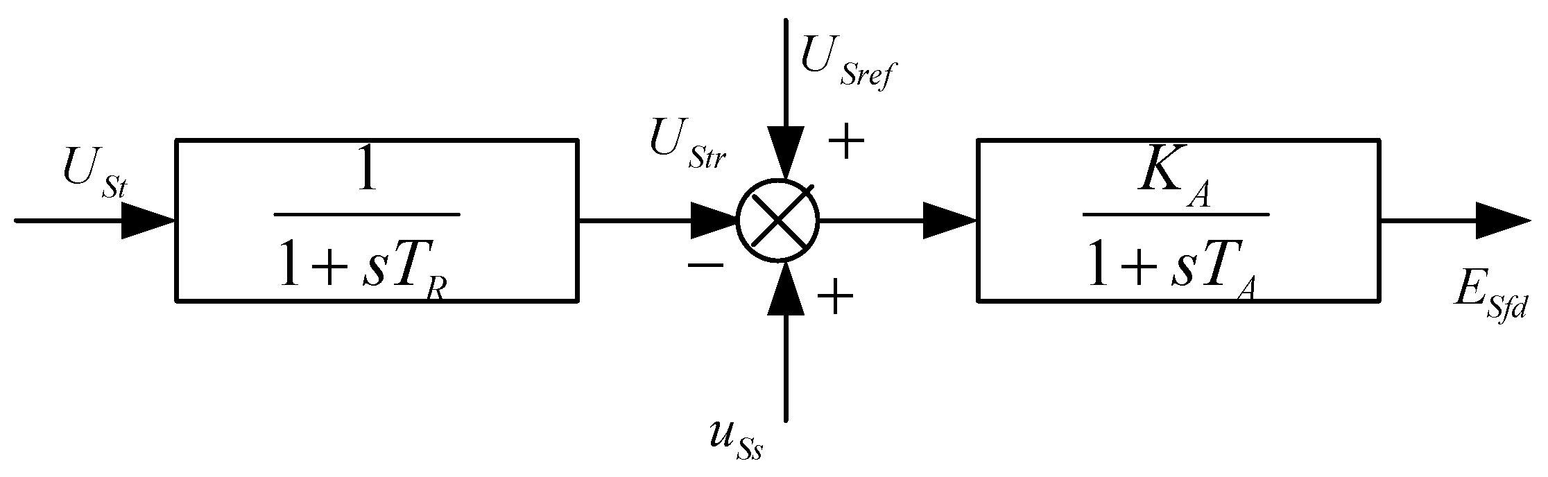
2.2.2. Model of the Synchronous Machine Excitation Control System
The transfer function of the excitation control system of the synchronous machine is shown in
Figure 5.
The linearized equations of the measurement loop and the excitation regulator are as follows:
where
is the terminal voltage of the synchronous machine,
is the output signal of the PSS system,
is the gain variable in the transfer function,
and
are the time constants in the transfer function.
2.2.3. Model of the Power System Stabilizer System
The PSS system shown in
Figure 6 was used, with the input signal being the synchronous machine’s own rotational speed.
The linearized equations of the synchronous machine PSS system are as follows:
where
,
,
are the intermediate variables, and
~
are the time constants in the transfer function.
2.3. Model of the Series-Compensated Line
First, through coordinate transformation, the d-q coordinate systems of the DFIG and synchronous machine were unified into a common d-q coordinate system synchronized with the infinite bus voltage in order to achieve accurate superposition of the grid current and consistency in the dynamic analysis of the system.
The actual level of series compensation in the grid was determined by the equivalent inductance and capacitance of the entire system. It can be modeled as:
where
is the series compensation level,
is the total capacitance of the entire system,
is the total inductive reactance of the entire system when only the compensation level of the line needs to be calculated, and
can be replaced by the inductive reactance value of the line.
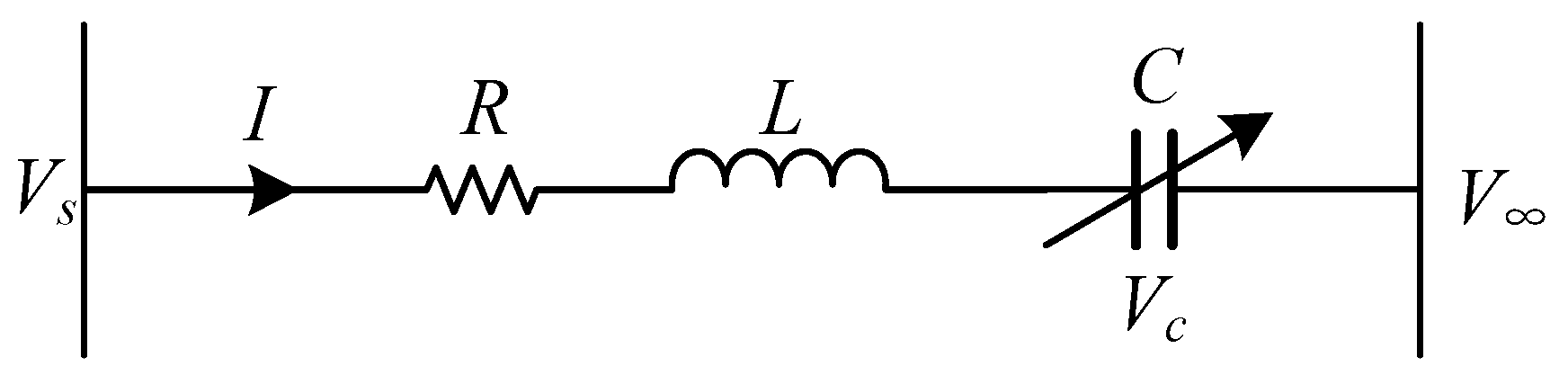
Neglecting the saturation effects of the transformers T1, T2, and T3 in
Figure 1 and combining their equivalent reactance with the reactance of the transmission line, the equivalent model of the series-compensated line could be obtained, as shown in
Figure 7.
The dynamic equations of the series-compensated transmission line in the
d-q reference frame are as follows [
36]:
where
is the equivalent reactance value obtained by combining the reactance of the transformer and the reactance of the line,
is the capacitance of the series-compensated line,
is the resistance of the series-compensated line,
and
are the
d- and
q-axis voltages of the series capacitor,
and
are the -
d and
q-axis voltages of the infinite bus, and
and
are the
d- and
q-axis currents of the series-compensated line.
2.4. State–Space Model of the Hybrid System
Equations (1) through (17) characterize the dynamic behavior of the hybrid system. By coupling these equations and linearizing the nonlinear differential equations of each individual component around the stable operating point, the system’s dynamics can be expressed in matrix form. This approach facilitates the derivation of a small-signal stability analysis model, which can be further utilized for stability analysis and performance evaluation under small perturbations. We considered
where
and
are column vectors that represent the state and algebraic variables of the entire system, respectively. The state variables consisted of 27 orders, including a 3th-order two-mass shaft system model, i.e.,
, a 4th-order DFIG model, i.e.,
, an 8th-order back-to-back rotor converters model, i.e.,
, an 8th-order synchronous machine model, i.e.,
, and a 4th-order series-compensated line model, i.e.,
. The algebraic variables, consisting of 12 orders, served as the input variables and can be expressed as follows:
.
Drawing from the hybrid system’s topology and the interrelations among its internal electrical parameters, the system’s algebraic equations can be linearized and represented in the following matrix form:
The simultaneous solution of Equations (18) and (19), along with the elimination of the algebraic variable
, led to the derivation of the characteristic matrix equation for the entire system as follows:
where
.
3. Analysis of the System Oscillation Characteristics and Case Study
3.1. Analysis of the Hybrid System Oscillation Characteristics
When a nonlinear system experiences small disturbances, its stability can be approximated by analyzing the linearized system. According to Lyapunov’s stability criterion, the stability of a linear system is determined by the eigenvalues of its state matrix. Hence, the stability of the wind power and pumped storage hybrid system constructed in this paper could be assessed by calculating the eigenvalues of its characteristic matrix . The criteria for the evaluation are as follows:
When the eigenvalue of the matrix is a real number, it corresponds to a non-oscillatory mode. A negative real eigenvalue indicates a decaying mode, with a larger absolute value resulting in faster decay. Conversely, a positive real eigenvalue represents a non-periodic unstable mode, and the larger its absolute value, the faster the divergence of the mode.
When the eigenvalue is complex and appears in conjugate pairs, such as
, it indicates a set of oscillatory modes. The damping of the oscillation is determined by the real part of the eigenvalue, while the frequency is related to the imaginary part. If the real part is negative, the oscillatory mode will gradually converge and stabilize; if the real part is positive, the oscillation will diverge, and the amplitude will increase over time. The frequency
and damping ratio
of the oscillation can be defined as:
Assuming a wind speed of 9 m/s, the actual active power of the DFIG system is approximately 307 MW. By calculating the eigenvalues of the state–space matrix, the oscillatory behavior of the wind power and pumped storage hybrid system under small disturbances can be analyzed. The system’s series compensation levels of the line were chosen as 25%, 40%, and 50%, and the operation of the synchronous pumped storage units under both generation and pumping modes was considered for the eigenvalue calculations of the matrix
. The results are shown in
Table 1, which lists six pairs of conjugate eigenvalues. The remaining eigenvalues were real and belonged to non-oscillatory modes, with negative values and relatively large magnitudes, indicating that these modes decayed rapidly and stabilized, and thus, further discussion is omitted.
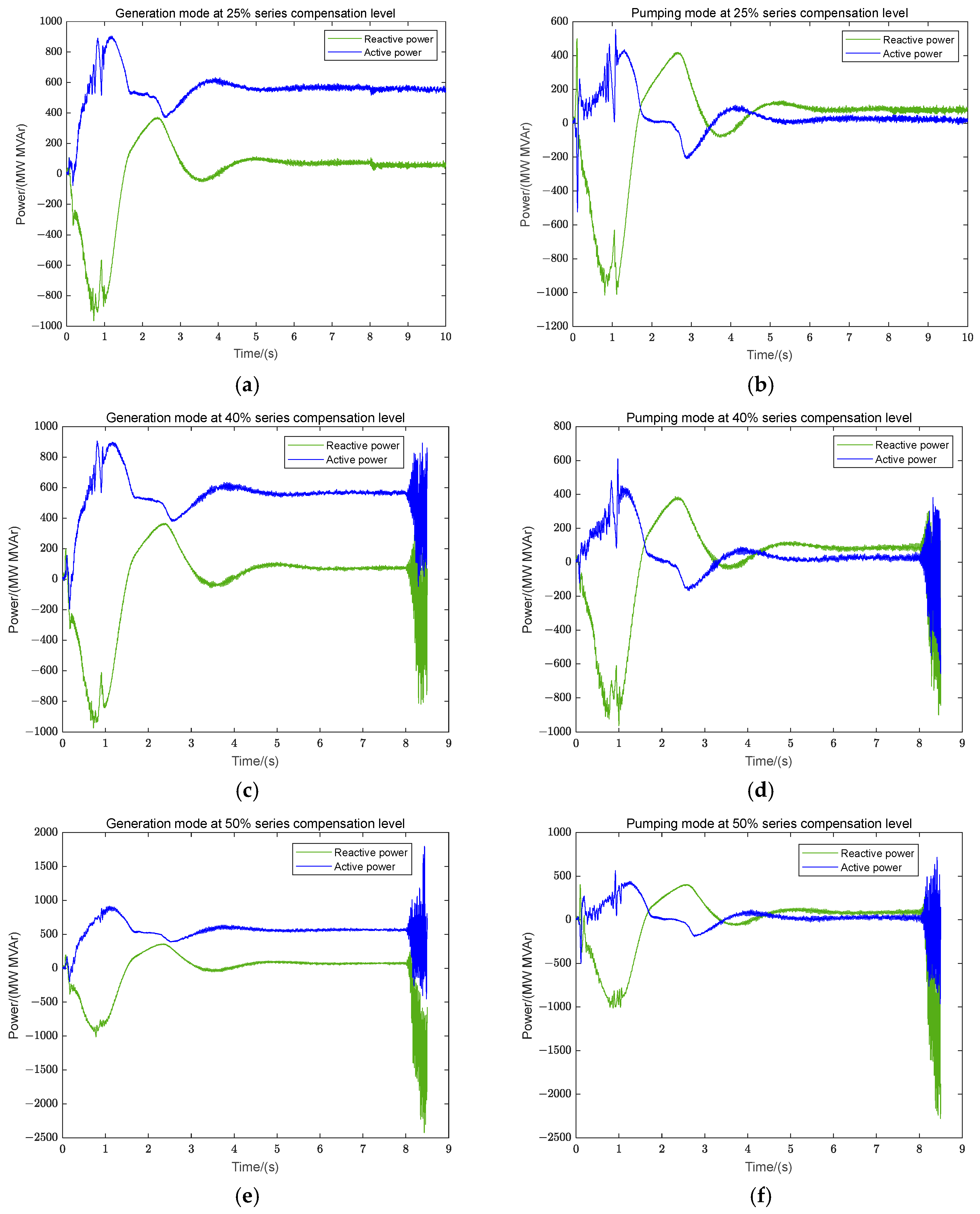
To verify the accuracy of the constructed state–space model, a corresponding PSCAD simulation model was established. After the system was started and reached a steady state, the L2 branch in
Figure 1 was disconnected at the 8th second, resulting in a series-compensated transmission line. In the simulation, the series compensation levels were set to 25%, 40%, and 50%, and the characteristics of the synchronous machine operating in both generation and pumping modes were considered to obtain the output power curves of the hybrid system at point A. The results are shown in
Figure 8.
As shown in
Table 1 and
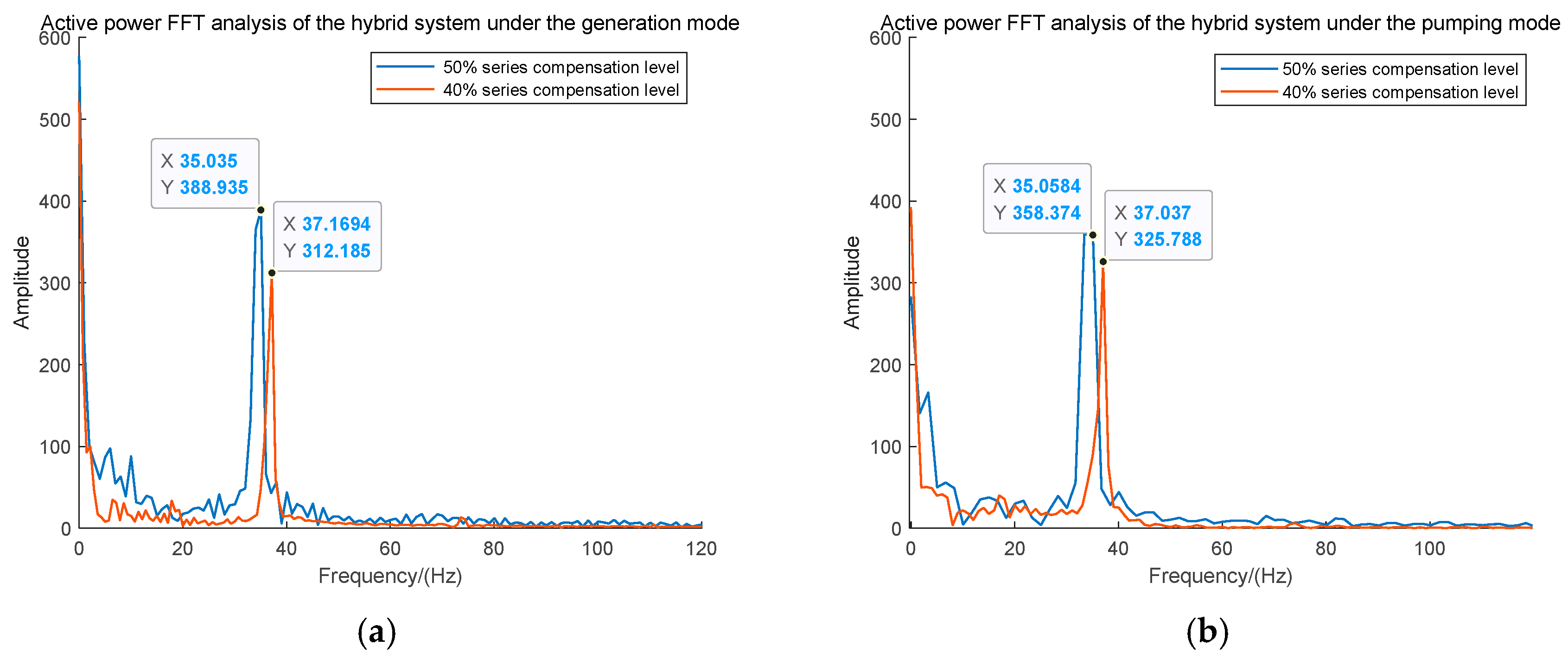
Figure 8, when the hybrid system of wind power and pumped storage experienced small disturbances under a low level of series compensation, the resulting oscillatory modes converged and stabilized. However, as the series compensation level increased, the oscillations gradually diverged. Therefore, a fast Fourier transform (FFT) was performed on the active power output of the hybrid system under these four divergent oscillation conditions to obtain the corresponding oscillation frequencies and amplitudes. The analysis results are shown in
Figure 9.
As shown in
Table 1, based on the eigenvalue corresponding to oscillation modes 3, 4, when the hybrid system’s synchronous pumped storage unit operated in generation mode, SSOs occurred under 50% and 40% series compensation levels, with oscillation frequencies of 36.51 Hz and 38.86 Hz, respectively. Additionally, as the series compensation level increased, the real part of the eigenvalues became larger, leading to more divergent oscillations. Compared to the results in
Figure 9, the FFT analysis of the power output curves from the PSCAD (version number 4.6.2) simulation model yielded oscillation frequencies of 35.04 Hz and 37.17 Hz, respectively, with the oscillation amplitude at the 50% series compensation level being greater than that at the 40% level. Similarly, when the synchronous pumped storage unit operated in pumping mode, the theoretically calculated oscillation frequencies were 36.50 Hz and 38.33 Hz, while the simulated frequencies were 35.06 Hz and 37.04 Hz. In both operating scenarios, the simulation results were consistent with the theoretical calculations, validating the accuracy of the developed model presented in this study.
In
Table 1, it is observed that under different operating modes and series compensation levels, the frequencies of modes 1,2 were always higher than the synchronous frequency, while the frequencies of modes 3,4 were always lower than the synchronous frequency. Moreover, the frequencies of these modes were symmetric with respect to the synchronous frequency, as their sum consistently approached
. Therefore, modes 1 and 2 were categorized as super-synchronous modes, while modes 3,4 were classified as sub-synchronous modes.
As also observed in
Table 1 and
Figure 9, under both operating modes, when the series compensation level was low, the real part of the eigenvalue for modes 3,4 was negative, indicating that the SSOs could converge, and the system could maintain stability. However, as the series compensation level increased, the oscillations associated with modes 3,4 began to diverge, while those associated with other modes remained convergent. Additionally, with higher series compensation levels, the real part of the eigenvalue for modes 3,4 gradually increased, while the imaginary part decreased. This indicates that higher series compensation levels significantly reduced the ability of SSOs to converge, leading to greater divergence and a gradual reduction in the corresponding SSO frequency. This dual effect exacerbates the risk of SSOs in highly series-compensated systems, highlighting the urgent need for targeted mitigation measures.
3.2. Model Simplification Method Based on Relative Participation Analysis
It can also be observed in
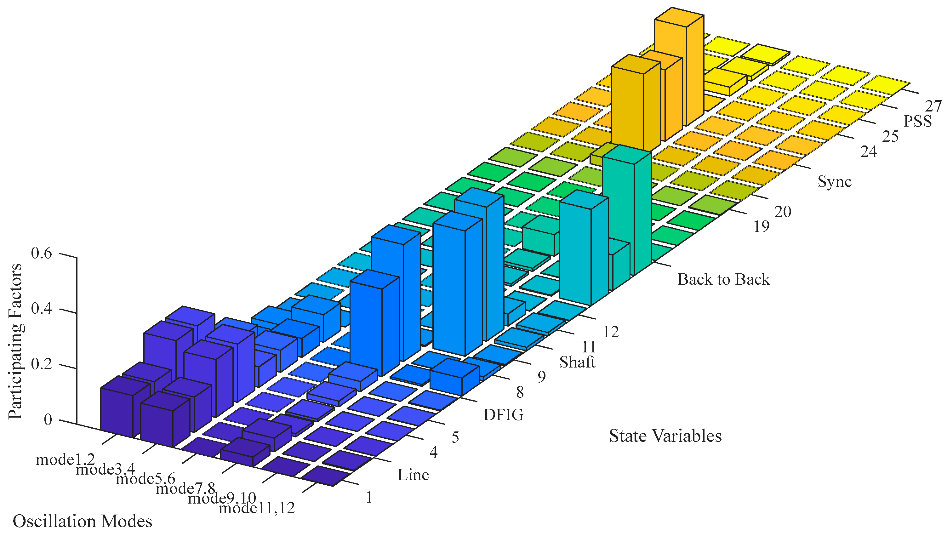
Table 1 that, except for modes 5,6, the eigenvalues of the other oscillation modes were essentially unaffected by the operating mode of the synchronous pumped storage unit, suggesting that they were unrelated to the state variables of the pumped storage unit. On the other hand, the eigenvalues of modes 5,6 remained largely unchanged with increasing levels of series compensation in the system, indicating that they were independent of the system parameters. This study focused on SSO issues, and relative participation analysis was performed only on the state–space matrix under the generation mode. The results are shown in
Figure 10.
As is shown
Figure 10, in this bar chart, the height of each bar represents the strength of the correlation between a state variable and each oscillation mode. The higher the bar, the stronger the correlation. The state variables 1 to 4 represent the variables associated with the transmission line, the state variables 5 to 8 represent the variables associated with the DFIG, the state variables 9 to 11 represent the variables associated with the wind turbine shaft system, and the state variables 12 to 19 represent the variables associated with the back-to-back converter. Furthermore, the state variables 20 to 24 represent the variables associated with the synchronous machine, whereas the state variables 25 to 27 represent the variables associated with the PSS.
As illustrated in
Figure 10, modes 1,2 and 3,4 were strongly correlated with the state variables of the transmission line and the DFIG. Since the state variables of the DFIG are governed by the rotor flux linkage, which is influenced by the rotor-side excitation controller, these oscillation modes are categorized as electrical oscillation modes. This suggests that the dynamic behaviors of the series-compensated line, the DFIG, and the rotor-side controller have significant impacts on both sub-synchronous and super-synchronous oscillation modes. Modes 7,8 were closely associated with the state variables of the DFIG but showed weak correlations with the back-to-back converter. Conversely, modes 11,12 exhibited strong correlations with the back-to-back converter and weaker associations with the DFIG parameters. Modes 9,10 depended heavily on the state variables of the wind turbine shaft system and were classified as mechanical oscillation modes. Meanwhile, modes 5,6 were only influenced by the state variables of the synchronous machine, with no significant interactions with the wind turbine or the transmission line. This observation aligns with the eigenvalue analysis results and validated the decoupled relationship among different machine types within the system.
In summary, the SSO phenomenon observed in the hybrid system with series-compensated transmission lines primarily arose from the coupling between the parameters of the DFIG and its controllers with the transmission line parameters, while it was unrelated to the synchronous machine. Therefore, SSO can be mitigated effectively by adjusting the rotor-side controller of the DFIG.
Since the SSO was unrelated to the state variables of the synchronous machine, and the synchronous machine was decoupled from the transmission line and DFIG model, a simplified modeling method suitable for SSO analysis can be proposed. When the focus of a study is solely on analyzing the SSO characteristics of a hybrid system, and the oscillation characteristics of the synchronous machine are not considered, the dynamic model of the synchronous machine can be omitted. Specifically, in Equation (18), the state and algebraic variables related to the synchronous machine can be excluded. However, the steady-state effects of the synchronous machine must still be accounted for, including the following aspects:
- (1)
The influence of the synchronous machine on the voltage magnitude and phase under steady-state conditions;
- (2)
Adjustments to the initial power flow conditions;
- (3)
Corrections to the initial steady-state parameters of the DFIG;
- (4)
The impact of the transformer T3 associated with the synchronous machine on the overall system impedance.
These adjustments to the initial steady-state conditions will directly affect the equilibrium point and impedance characteristics of the system, thereby influencing the small-signal model of the wind turbine and transmission line. Therefore, even if the dynamic model of the synchronous machine is simplified, it is essential to consider its steady-state effects on the overall system during the modeling process to ensure the reliability and accuracy of the final results.
5. Conclusions
This study investigated the SSO characteristics and mitigation strategies in a hybrid power system, where a wind farm based on a DFIG was interconnected with a synchronous pumped storage unit via a series-compensated transmission line. A modular modeling approach was adopted to integrate the dynamic interactions of key components, resulting in a state–space small-signal model for the hybrid system. This model includes the wind turbine shaft system, the DFIG, back-to-back converters, a synchronous machine, an excitation control system, a PSS system, and a series-compensated transmission line. The small-signal stability analysis, based on eigenvalue analysis and relative participation analysis, was employed to identify the dominant oscillation modes. Time-domain simulations were carried out using PSCAD, and the results were compared with theoretical calculations to verify the accuracy of the model. Moreover, based on the analysis of the oscillation characteristics, a simplified modeling method that excludes the dynamic model of the synchronous machine is proposed to enhance computational efficiency. Additionally, an SSDC was designed for the rotor-side converter of the DFIG. This study provides new methods and insights into addressing SSO issues in hybrid renewable energy power systems dominated by doubly fed wind turbines. The main conclusions of this study are as follows:
- (1)
The SSO modes induced by connecting the hybrid system to the grid via a series-compensated transmission line are strongly correlated with the electrical state variables of the line capacitance, inductance, the DFIG, and its rotor-side control system. In contrast, the state variables of the synchronous pumped storage unit showed negligible participation in the dominant SSO modes and have no significant correlation with the internal oscillation modes of wind turbines. This indicates that the DFIG and the synchronous machine are essentially decoupled and do not influence each other.
- (2)
The series compensation level has a critical impact on SSO stability. When the series compensation level is low, the system can remain stable even after a fault. However, as the compensation level increases, SSO becomes progressively more pronounced, eventually driving the system toward instability.
- (3)
Given the weak correlation between SSO and the synchronous machine, the dynamic model of the synchronous machine can be omitted when constructing a small-signal model. However, it is essential to consider the effects of the synchronous machine’s integration on the system’s steady-state magnitude, phase, initial power flow conditions, and line impedance. These parameters can significantly influence the system’s dynamic characteristics and affect the accuracy of the wind turbine small-signal model, which is critical for accurately predicting the SSO behavior.
- (4)
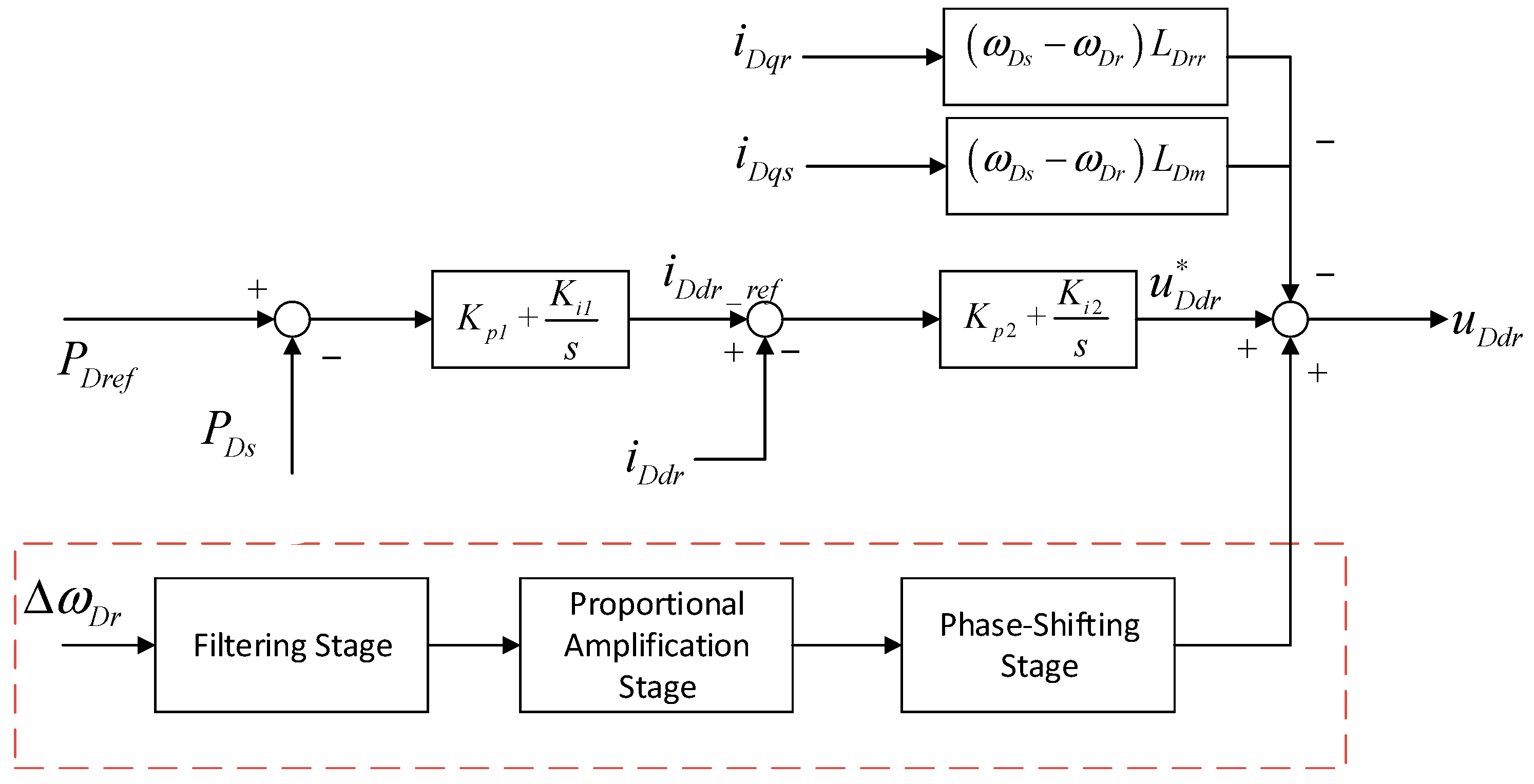
Through the relative participation analysis, it was determined that the rotor-side converter control dominated the SSO mode. By introducing an SSDC into the rotor voltage regulation loop, the controller can effectively suppress the SSO without affecting the primary power regulation functionalities of the DFIG.
At the same time, this paper also has certain limitations, such as being restricted to the analysis of small-signal model small-disturbance stability, with input wind speed and controller parameters set at constant values over short time scales. However, this paper provides a theoretical basis for similar hybrid wind power and synchronous pumped storage systems, to effectively prevent the harm caused by sub-synchronous oscillations in the system. Based on the above conclusions, future research should focus on developing real-time oscillation detection algorithms and data-driven control frameworks to enhance the identification and mitigation of SSO, advancing coordinated damping control strategies between DFIG-based SSDCs and other energy storage devices, and improving the scalability and adaptability of these methods in ultra-high renewable penetration grids with hybrid AC/DC transmission systems.


