
A New Methodology to Fabricate Polymer–Metal Parts Through Hybrid Fused Filament Fabrication

 , ,
, ,  ,
,  , and
, and 
Abstract
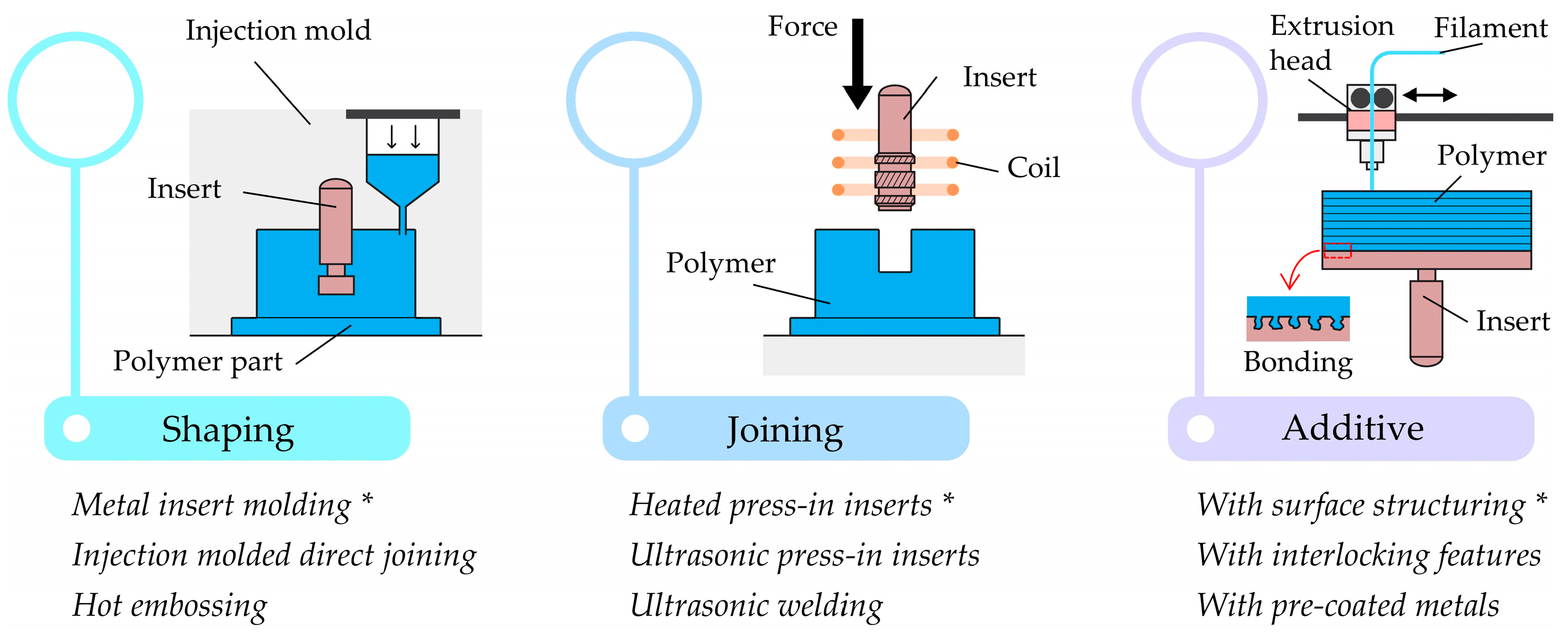
1. Introduction
2. Materials and Methods
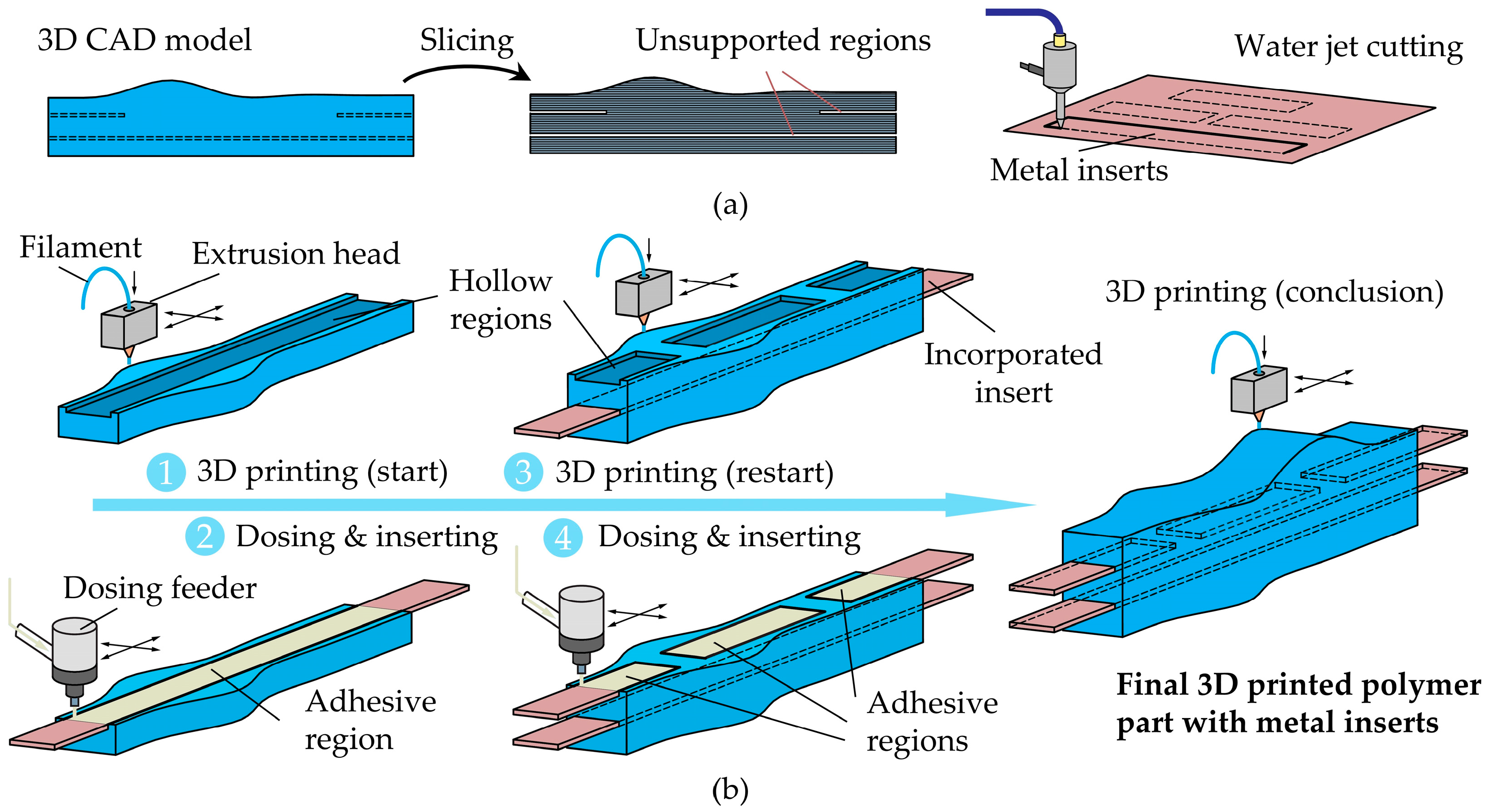
2.1. Hybrid Additive Manufacturing Sequence
2.2. Additive Manufacturing and Adhesive Bonding
2.3. Experimental Workplan
2.4. Fabrication and Testing of Prototypes
3. Results and Discussion
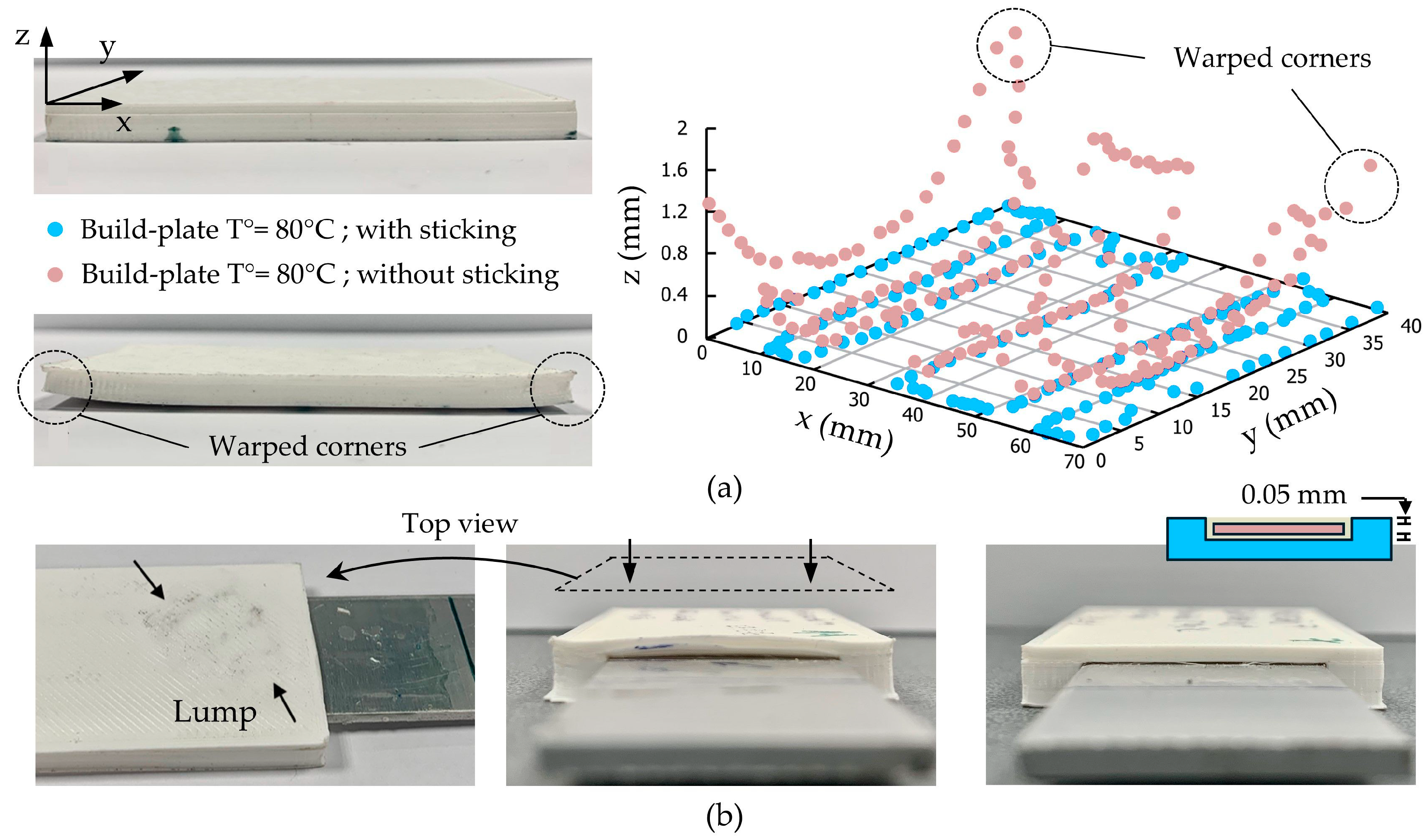
3.1. Build Quality
3.2. Tensile Lap-Shear Tests
3.3. Three-Point Bending Tests
3.4. Corner Connectors with Metal Inserts
4. Conclusions
Author Contributions
Funding
Institutional Review Board Statement
Informed Consent Statement
Data Availability Statement
Acknowledgments
Conflicts of Interest
Appendix A

| ID | Build-Plate Temperature (°C) | Metal Temperature (°C) | Surface Quality | ID | Build-Plate Temperature (°C) | Metal Temperature (°C) | Surface Quality |
|---|---|---|---|---|---|---|---|
| 1 | 60 | RT 1 | AS 2 | 13 | 80 | RT | AS |
| 2 | 60 | RT | #80 | 14 | 80 | RT | #80 |
| 3 | 60 | RT | #500 | 15 | 80 | RT | #500 |
| 4 | 60 | 70 | AS | 16 | 80 | 70 | AS |
| 5 | 60 | 70 | #80 | 17 | 80 | 70 | #80 |
| 6 | 60 | 70 | #500 | 18 | 80 | 70 | #500 |
| 7 | 60 | 90 | AS | 19 | 80 | 90 | AS |
| 8 | 60 | 90 | #80 | 20 | 80 | 90 | #80 |
| 9 | 60 | 90 | #500 | 21 | 80 | 90 | #500 |
| 10 | 60 | 160 | AS | 22 | 80 | 160 | AS |
| 11 | 60 | 160 | #80 | 23 | 80 | 160 | #80 |
| 12 | 60 | 160 | #500 | 24 | 80 | 160 | #500 |
| ID | Adherend | Mixed | Adhesive | ID | Adherend | Mixed | Adhesive |
|---|---|---|---|---|---|---|---|
| 1 | ⬤ | 13 | ⬤ | ||||
| 2 | ⬤ | 14 | ⬤ | ||||
| 3 | ⬤ | 15 | ⬤ | ||||
| 4 | ⬤ | 16 | ⬤ | ||||
| 5 | ⬤ | 17 | ⬤ | ||||
| 6 | ⬤ | 18 | ⬤ | ||||
| 7 | ⬤ | 19 | ⬤ | ||||
| 8 | ⬤ | 20 | ⬤ | ||||
| 9 | ⬤ | 21 | ⬤ | ||||
| 10 | ⬤ | 22 | ⬤ | ||||
| 11 | ⬤ | 23 | ⬤ | ||||
| 12 | ⬤ | 24 | ⬤ |
References
- Rezvani Ghomi, E.; Khosravi, F.; Saedi Ardahaei, A.; Dai, Y.; Neisiany, R.E.; Foroughi, F.; Wu, M.; Das, O.; Ramakrishna, S. The Life Cycle Assessment for Polylactic Acid (PLA) to Make It a Low-Carbon Material. Polymers 2021, 13, 1854. [Google Scholar] [CrossRef]
- Liu, G.; Zhang, X.; Chen, X.; He, Y.; Cheng, L.; Huo, M.; Yin, J.; Hao, F.; Chen, S.; Wang, P.; et al. Additive manufacturing of structural materials. Mater. Sci. Eng. R Rep. 2021, 145, 100596. [Google Scholar] [CrossRef]
- Carradò, A.; Faerber, J.; Niemeyer, S.; Ziegmann, G.; Palkowski, H. Metal/Polymer/Metal Hybrid Systems: Towards Potential Formability Applications. Compos. Struct. 2011, 93, 715–721. [Google Scholar] [CrossRef]
- Pragana, J.P.M.; Contreiras, T.R.; Bragança, I.M.F.; Silva, C.M.A.; Alves, L.M.; Martins, P.A.F. Joining by Forming of Metal–Polymer Sandwich Composite Panels. Proc. Inst. Mech. Eng. Part B J. Eng. Manuf. 2019, 233, 2089–2098. [Google Scholar] [CrossRef]
- Zhao, S.; Kimura, F.; Kadoya, S.; Kajihara, Y. Experimental analysis on mechanical interlocking of metal–polymer direct joining. Precis. Eng. 2020, 61, 120–125. [Google Scholar] [CrossRef]
- Kimura, F.; Kadoya, S.; Kajihara, Y. Effects of molding conditions on injection molded direct joining under various surface fine-structuring. Int. J. Adv. Manuf. Technol. 2019, 101, 2703–2712. [Google Scholar] [CrossRef]
- Kolew, A.; Münch, D.; Sikora, K.; Worgull, M. Hot embossing of micro and sub-micro structured inserts for polymer replication. Microsyst. Technol. 2011, 17, 609–618. [Google Scholar] [CrossRef]
- Sollogoub, C.; Felder, E.; Demay, Y.; Agassant, J.F.; Deparis, P.; Mikler, N. Thermomechanical analysis and modeling of the extrusion coating process. Polym. Eng. Sci. 2008, 48, 1634–1648. [Google Scholar] [CrossRef]
- Kastner, T.; Troschitz, J.; Vogel, C.; Behnisch, T.; Gude, M.; Modler, N. Investigation of the Pull-Out Behaviour of Metal Threaded Inserts in Thermoplastic Fused-Layer Modelling (FLM) Components. J. Manuf. Mater. Process. 2023, 7, 42. [Google Scholar] [CrossRef]
- Groschitz, J.; Gröger, B.; Würfel, V.; Kupfer, R.; Gude, M. Joining Processes for Fibre-Reinforced Thermoplastics: Phenomena and Characterisation. Materials 2022, 15, 5454. [Google Scholar] [CrossRef]
- Novák, L.; Fojtl, L.; Kadlečková, M.; Maňas, L.; Smolková, I.; Musilová, L.; Minařík, A.; Mráček, A.; Sedláček, T.; Smolka, P. Surface Modification of Metallic Inserts for Enhancing Adhesion at the Metal–Polymer Interface. Polymers 2021, 13, 4015. [Google Scholar] [CrossRef] [PubMed]
- Ribeiro, I.; Matos, F.; Jacinto, C.; Salman, H.; Cardeal, G.; Carvalho, H.; Godina, R.; Peças, P. Framework for Life Cycle Sustainability Assessment of Additive Manufacturing. Sustainability 2020, 12, 929. [Google Scholar] [CrossRef]
- Hoehr, L.; Bavendiek, J.; Sackmann, J.; Schomburg, W.K. Ultrasonic welding of polymer micro fluidic devices by inserting metal parts. Microsyst. Technol. 2018, 25, 673–681. [Google Scholar] [CrossRef]
- Pragana, J.P.M.; Braganca, I.M.F.; Silva, C.M.A.; Martins, P.A.F. Hybrid wire-arc additive manufacturing of conformal cooling channels: A feasibility study. Int. J. Precis. Eng. Manuf. Green Technol. 2023, 10, 45–57. [Google Scholar] [CrossRef]
- Butt, J.; Shirvani, H. Experimental analysis of metal/plastic composites made by a new hybrid method. Addit. Manuf. 2018, 22, 216–222. [Google Scholar] [CrossRef]
- Falck, R.; Goushegir, S.M.; dos Santos, J.F.; Amancio-Filho, S.T. AddJoining: A novel additive manufacturing approach for layered metal-polymer hybrid structures. Mater. Lett. 2018, 217, 211–214. [Google Scholar] [CrossRef]
- Alhmoudi, A.; Sheikh-Ahmad, J.; Almaskari, F.; Bojanampati, S. Joining of polymer to metal using material extrusion additive manufacturing. Int. J. Adv. Manuf. Technol. 2023, 129, 3303–3319. [Google Scholar] [CrossRef]
- Ozlati, A.; Movahedi, M.; Tamizi, M.; Tartifzadeh, Z.; Alipour, S. An alternative additive manufacturing-based joining method to make Metal/Polymer hybrid structures. J. Manuf. Process. 2019, 45, 217–226. [Google Scholar] [CrossRef]
- Cheng, P.; Wang, K.; Le Duigou, A.; Liu, J.; Liu, Z.; Peng, Y.; Ahzi, S. A Novel Dual-Nozzle 3D Printing Method for Continuous Fiber Reinforced Composite Cellular Structures. Compos. Commun. 2023, 37, 101448. [Google Scholar] [CrossRef]
- Dikshit, V.; Goh, G.D.; Nagalingam, A.P.; Goh, G.L.; Yeong, W.Y. Recent Progress in 3D Printing of Fiber-Reinforced Composite and Nanocomposites. In Fiber-Reinforced Nanocomposites: Fundamentals and Applications; Elsevier: Amsterdam, The Netherlands, 2020; pp. 371–394. [Google Scholar]
- Ben Said, L.; Karray, S.; Zghal, W.; Hentati, H.; Ayadi, B.; Chabir, A.; Alhadri, M. Investigation of Short Carbon Fiber-Reinforced Polylactic Acid Composites Blades for Horizontal Axis Wind Turbines: Mechanical Strength and Energy Efficiency of Fused Filament Fabrication-Printed Blades. J. Compos. Sci. 2025, 9, 118. [Google Scholar] [CrossRef]
- Bikas, H.; Lianos, A.K.; Stavropoulos, P. A design framework for additive manufacturing. Int. J. Adv. Manuf. Technol. 2019, 103, 3769–3783. [Google Scholar] [CrossRef]
- Pragana, J.P.M.; Sampaio, R.F.V.; Bragança, I.M.F.; Silva, C.M.A.; Martins, P.A.F. Hybrid metal additive manufacturing: A state–of–the-art review. Adv. Ind. Manuf. Eng. 2021, 2, 100032. [Google Scholar] [CrossRef]
- Li, X.; Liu, F.; Gong, N.; Huang, P.; Yang, C. Enhancing the joining strength of injection-molded polymer-metal hybrids by rapid heating and cooling. J. Mater. Process. Technol. 2017, 249, 386–393. [Google Scholar] [CrossRef]
- Ingeo™ Biopolymer 4043D Technical Data Sheet. Available online: https://www.natureworksllc.com/~/media/Files/NatureWorks/Technical-Documents/Technical-Data-Sheets/TechnicalDataSheet_4043D_3D-monofilament_pdf.pdf (accessed on 25 April 2025).
- Pragana, J.P.M.; Sampaio, R.F.V.; Bragança, I.M.F.; Silva, C.M.A.; Nielsen, C.V.; Martins, P.A.F. Macro-Scale Finite Element Simulation of Wire-Arc Additive Manufacturing. Proc. Inst. Mech. Eng. Part L J. Mater. Des. Appl. 2025, 239, 1013–1022. [Google Scholar] [CrossRef]
- ISO 4587:2003; Adhesives—Determination of Tensile Lap-Shear Strength of Rigid-to-Rigid Bonded Assemblies. International Organization for Standardization: Geneva, Switzerland, 2003.
- ISO 7438:2016; Metallic Materials—Bend Test. International Organization for Standardization: Geneva, Switzerland, 2016.
- R2u Modular Systems: New Solutions for the Modular Construction Industry. 2023. Available online: https://r2utechnologies.pt/ (accessed on 25 April 2025).
- Ramli, F.R.; Nazan, M.A.; Alkahari, M.R.; Abdullah, M.A.; Sudin, M.N.; Herawan, S.G. Dimensional Accuracy of Fused Filament Fabrication by Cassava Adhesion on Printing Platform. J. Adv. Manuf. Technol. 2020, 14, 2. [Google Scholar]
- ISO 10365:2022; Adhesives—Designation of Main Failure Patterns. International Organization for Standardization: Geneva, Switzerland, 2022.


| ID | Build-Plate Temperature (°C) | Metal Temperature (°C) | Surface Quality |
|---|---|---|---|
| 1–24 | 60; 80 | RT 1; 70; 90; 160 | AS 2; #80; #500 |
Disclaimer/Publisher’s Note: The statements, opinions and data contained in all publications are solely those of the individual author(s) and contributor(s) and not of MDPI and/or the editor(s). MDPI and/or the editor(s) disclaim responsibility for any injury to people or property resulting from any ideas, methods, instructions or products referred to in the content. |
© 2025 by the authors. Licensee MDPI, Basel, Switzerland. This article is an open access article distributed under the terms and conditions of the Creative Commons Attribution (CC BY) license (https://creativecommons.org/licenses/by/4.0/).
Share and Cite
Silva, S.F.; Rosado, P.M.S.; Sampaio, R.F.V.; Pragana, J.P.M.; Bragança, I.M.F.; Assunção, E.; Silva, C.M.A. A New Methodology to Fabricate Polymer–Metal Parts Through Hybrid Fused Filament Fabrication. Sustainability 2025, 17, 4254. https://doi.org/10.3390/su17104254
Silva SF, Rosado PMS, Sampaio RFV, Pragana JPM, Bragança IMF, Assunção E, Silva CMA. A New Methodology to Fabricate Polymer–Metal Parts Through Hybrid Fused Filament Fabrication. Sustainability. 2025; 17(10):4254. https://doi.org/10.3390/su17104254
Chicago/Turabian StyleSilva, Sofia F., Pedro M. S. Rosado, Rui F. V. Sampaio, João P. M. Pragana, Ivo M. F. Bragança, Eurico Assunção, and Carlos M. A. Silva. 2025. "A New Methodology to Fabricate Polymer–Metal Parts Through Hybrid Fused Filament Fabrication" Sustainability 17, no. 10: 4254. https://doi.org/10.3390/su17104254
APA StyleSilva, S. F., Rosado, P. M. S., Sampaio, R. F. V., Pragana, J. P. M., Bragança, I. M. F., Assunção, E., & Silva, C. M. A. (2025). A New Methodology to Fabricate Polymer–Metal Parts Through Hybrid Fused Filament Fabrication. Sustainability, 17(10), 4254. https://doi.org/10.3390/su17104254