1. Introduction
Harnessing the potential of solar energy for fuel production can be achieved through the use of concentrated solar power to drive chemical reactions. This method offers a promising option for utilizing the abundant solar energy available and converting it into a reliable source of fuel. Several researchers have conducted a thorough investigation of a solar-driven thermochemical redox cycle that utilizes metal oxide (MO) in the process of splitting H
2O/CO
2. The main objective of this cycle is to produce H
2 gas through the thermochemical H
2O-splitting (WS) reaction, which is driven by solar power. The H
2 produced from this reaction can be used directly as a fuel with ease. One alternative approach to producing energy is through the use of solar CO generated via the thermochemical CO
2-splitting (CDS) reaction. This approach involves the combination of solar CO with H
2 to synthesize solar syngas [
1]. One of the key benefits of this method is that it helps to reduce the dangerous consequences of CO
2 emissions [
2] by recycling it into a chemical fuel. In addition, the use of solar thermochemical CDS can provide a more sustainable and eco-friendly solution to energy production. Extensive research has been conducted on various MOs for solar thermochemical cycles, including Fe
3O
4/FeO [
3,
4], ZnO/Zn [
5], SnO
2/SnO [
6], ferrites [
7], doped ceria [
8,
9], and perovskite [
10,
11] materials. Two prestigious European institutions from Switzerland and France have paid special attention to the ZnO/Zn and SnO
2/SnO cycles. The ZnO/Zn-based redox system has been studied extensively by the Paul Scherrer Institute in Switzerland [
12], whereas the SnO
2/SnO-based redox cycle has been considerably investigated by PROMES-CNRS in France [
13].
During the early years of the ZnO/Zn cycle (before 2005), the main focus was on (a) using solar thermal energy to decompose ZnO [
14], (b) studying the crystallization and condensation of Zn with variations in O
2 concentration [
15], (c) analyzing the kinetics of the thermal reduction (TR) of ZnO [
16], (d) evaluating the economics of the ZnO/Zn cycle [
17], and (e) designing solar reactors suitable for this process [
18]. After 2005, application of an aerosol reactor for the Zn hydrolysis [
19,
20], thermal decomposition of ZnO in a fluid wall reactor [
21], the kinetics of the WS and combined WS + CDS using a thermogravimetric analyzer [
22,
23], and application of a 10 kW solar reactor for the TR of ZnO [
24] were investigated. A team of researchers from ETH Zurich and the Paul Scherrer Institute recently conducted two experimental campaigns to test a pilot-scale 100 kW solar reactor for the thermal decomposition of ZnO [
25,
26]. The tests were conducted using a 1 MW solar furnace at PROMES-CNRS, France.
In the case of the SnO
2/SnO redox cycle, Abanades et al. [
27] reported that SnO
2 needs to be heated to a temperature above 1873 K at atmospheric pressure to undergo thermal decomposition into SnO. Charvin et al. [
13] estimated the activation energy of SnO
2 thermal decomposition as 394.8 kJ/mol using thermogravimetry. Chambon et al. [
28] studied the kinetics of SnO
2/SnO-driven WS and determined the order to be one and the activation energy to be 122 kJ/mol. Chambon et al. [
29] conducted an in-depth analysis of the recombination process of SnO and O
2, which occurs during the quenching step. Abanades et al. [
30] conducted a study to investigate the effectiveness of utilizing the SnO
2/SnO redox cycle for a combined WS and CDS process by using a thermogravimetric analyzer.
Although the redox cycles of ZnO/Zn and SnO
2/SnO have been extensively investigated, researchers in the solar thermochemical community are seeking a more energy-efficient redox cycle. There is an option available in this category called the GeO
2/GeO redox cycle. In 2009, Kang et al. [
31] investigated the GeO
2/GeO WS cycle and found that the requirement of the TR temperature (
) was lower for the GeO
2/GeO cycle than for the ZnO/Zn and SnO
2/SnO cycles. The authors further reported that the process efficiency associated with the GeO
2/GeO WS cycle was higher compared to the ZnO/Zn and SnO
2/SnO WS cycles. Recently, Bhosale [
32] conducted a thermodynamic study of the GeO
2/GeO WS cycle. He estimated process parameters as a function of O
2 partial pressure, TR, and WS temperatures.
In this study, Bhosale and his team of undergraduate researchers develop a thermodynamic model for the CDS redox cycle based on GeO2/GeO. Various process parameters are calculated by considering different temperatures, molar flow rates of inert sweep gas (), and the inclusion of gas separators, heat exchangers, heaters, coolers, and fuel cell for determining the solar-to-fuel energy conversion efficiency (). At the end of the study, a detailed comparison is provided between three redox CDS cycles: GeO2/GeO, ZnO/Zn, and SnO2/SnO. The comparison is based on .
2. Thermodynamic Model
The process of generating CO through the solar-driven GeO
2/GeO-based CDS redox cycle involves two steps, as described in the following reactions.
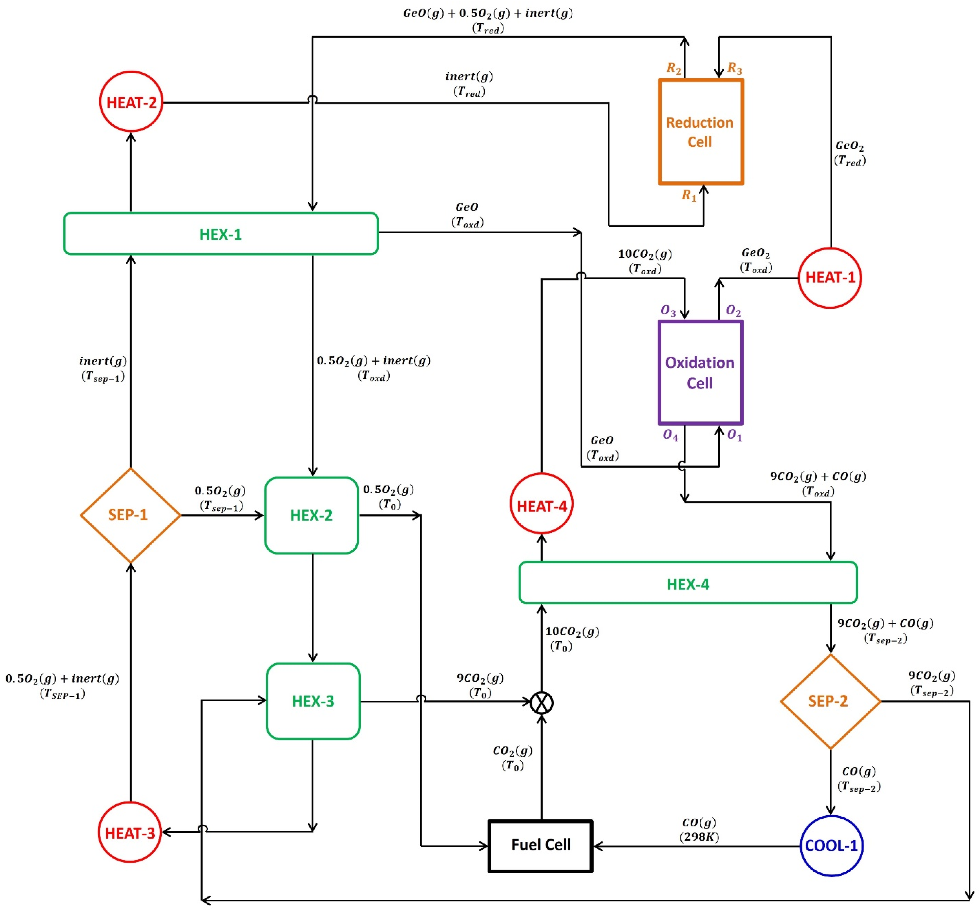
The model presented in
Figure 1 was used to examine the thermodynamic feasibility of the GeO
2/GeO-based CDS redox cycle. The thermodynamic model operates under the assumption that the gas behaves ideally and the system is in a steady state. The processes of thermal reduction and CDS reaction are carried out in two separate cells, one for reduction and the other for oxidation. Both cells are operated at a constant temperature, i.e., thermal reduction (
) and CDS temperature (
). The reduction cell operates at a higher temperature compared to the oxidation cell. During the GeO
2 decomposition process, a continuous
(N
2) is employed to facilitate a reduction at
. The thermodynamic evaluation is carried out by maintaining a consistent flow of GeO
2, with a rate of 1 mole per second.
After exiting from separator-1 and passing through heater-2, the recycled inert sweep gas stream and GeO
2 from the oxidation cell after CDS reaction enter the reduction cell where GeO
2 undergoes thermal decomposition. This results in the production of gaseous GeO and O
2. It is assumed that GeO
2 and the gaseous species have reached equilibrium. Equation (3) is utilized to estimate the amount of energy needed for the thermal reduction of GeO
2.
To facilitate the removal of gaseous products, namely, GeO and O2, from the reduction cell, an inert sweep gas is employed. The gas mixture, containing GeO, O2, and inert sweep gas, is cooled below the melting point of GeO by using a gas-to-gas heat exchanger, HEX-1, to avoid the recombination of gaseous products at higher temperatures. The solid GeO is transferred from HEX-1 to the oxidation cell, where it is re-oxidized to GeO2 at through a CDS reaction. It is assumed that 100% conversion occurs during thermal reduction and CDS when evaluating the presented thermodynamic model.
To simulate the practical operation of an oxidation cell, CDS reactions use an excess of CO
2 of 10 times the stoichiometric requirement. As shown in
Figure 1, CO
2 enters the oxidation cell at state O
3, while GeO enters at state O
1. After the re-oxidation reaction, GeO exits the oxidation cell as state O
2, while any remaining CO
2 and produced CO gases exit as a mixture at state O
4. As the CDS reaction is exothermic, the energy released by the oxidation cell is estimated using the following formula:
Furthermore, Equation (5) is applied to calculate the energy required to heat the GeO
2 from
to
with the help of heater-1.
Separator-2, which is operated at
= 400 K, separates CO from unreacted CO
2. The operating efficiency of separator-2 is assumed to be 15%, with a 99.9% separation of CO from CO
2 [
33]. Before entering separator-2, the CO
2/CO gas mixture is cooled from 1000 K to 400 K by passing through HEX-4. The required energy for achieving the desired separation is determined using the following equations:
The model incorporates a prototypical fuel cell that operates with 100% efficiency by utilizing CO and O
2 to complete the cycle. For the operation of this fuel cell, cooler-1 decreases the temperature of CO exiting separator-2 from 400 K to 298 K. The CO is consumed in the fuel cell, producing CO
2 that combines with unreacted CO
2 from HEX-3. This combined CO
2 stream is conveyed to the oxidation cell by passing through HEX-4 and heater-4. To find out the amount of energy needed to heat the CO
2, we use an energy balance calculation, which is presented below.
For the reduction and fuel cells to function smoothly, there needs to be a continuous and uninterrupted supply of inert gas and O
2. Recycling the inert gas that exits the reduction cell is crucial to improve the process’s economics. Therefore, separator-1 is installed in the cycle to separate the inert gas and O
2, which exit the reduction cell as a gas mixture, after performing the thermal decomposition of GeO
2. To achieve this gas separation, it is assumed that the ion transport membrane technology will be applied [
34]. For the presented cycle, separator-1 is assumed to be operated at 1123 K with an efficiency of 15%. By passing the inert gas and O
2 mixture through HEX-2, HEX-3, and heater-3, it is heated because the operating temperature of separator-1 is higher than the CDS temperature. Below is the energy balance associated with these three units.
According to the second law of thermodynamics, the thermal energy required for separating the inert sweep gas and O
2 is computed using the entropy of mixing for each stream as follows [
33]:
The O
2 that has been separated from the inert gas at 1123 K is cooled in HEX-2 to 298 K before being transferred to the fuel cell. In contrast, the inert sweep gas is heated from 1123 K up to
by passing through HEX-1 and heater-2. In HEX-1, the energy released during cooling of a gas mixture containing inert gas/O
2/GeO is used to heat the inert sweep gas. The heater-2 provides the additional energy required for the inert gas heating.
The efficiency of converting solar energy into fuel using the GeO
2/GeO CDS cycle can be calculated using the following equation:
where
In order to determine the complete solar energy necessary for powering the cycle, it is essential to calculate the overall thermal energy required for performing the reactions as well as running the supplementary units, utilizing the following equation.
The re-radiation losses associated with the cycle are estimated as per the following equation:
The values of the constant parameters used in this study are listed in
Table 1.
3. Results and Discussion
According to the published literature [
22,
29], achieving a cavity temperature in the range of 1600 K to 2000 K is feasible using concentrated solar power for a 100 kW solar reactor. The research teams from Switzerland [
25,
26] and Germany [
35] have successfully demonstrated solar thermochemical reactions with reasonable energy efficiency despite the high temperatures required. Therefore, in this study, the thermodynamic model presented in
Figure 1 is evaluated by varying the
from 1600 K to 2000 K, and by keeping
and
steady at 0.5 and 1000 K.
As a first step towards the estimation of the
, it is crucial to estimate the
needed for the complete thermal dissociation of GeO
2 in the temperature range selected for the
. By performing the equilibrium composition analysis using the HSC Chemistry software and its database, the variation in the
as a function of the change in the
is estimated. The results obtained are reported in
Figure 2. According to the results obtained, the need for
to achieve 100% thermal reduction of GeO
2 reduces as the
increase from 1600 K to 2000 K. As the
increases from 1600 K to 1800 K and 2000 K, the
needed decreases from 100 mol/s to 44 mol/s and 4 mol/s, respectively.
Equation (3) is utilized for the determination of
at various
. The energy used to preheat the inert sweep gas and GeO
2 is not considered when calculating
. This is because both streams are preheated before entering the reduction cell. Because of the exclusion of the preheating of the inert sweep gas and GeO
2, the enthalpies of the individual components involved in the reduction step determine the
. With the rise in the
from 1600 to 2000 K, the enthalpies of GeO
2 (reactant) and GeO and O
2 (products) increase by 31.4 kJ/mol, 15.91 kJ/mol, and 15.9 kJ/mol, respectively.
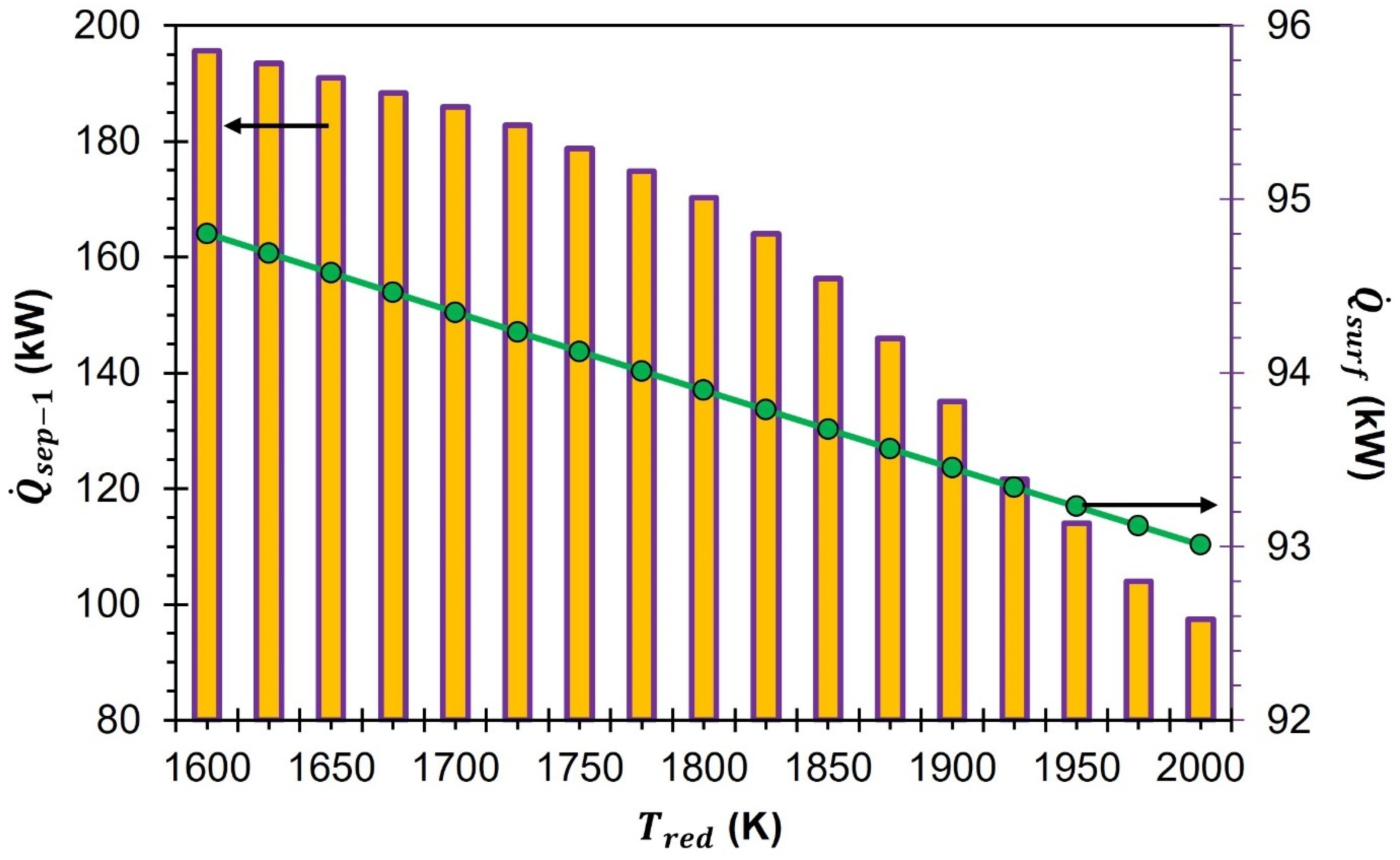
Figure 3 shows the impact of increasing
from 1600 to 2000 K on
. The results presented show that
at 2000 K is 9.0 kW lower than at 1600 K.
decreases when
increases from 1600 to 2000 K. This happens because the enthalpy of the reactant GeO
2 increases more than the enthalpies of the products GeO and O
2.
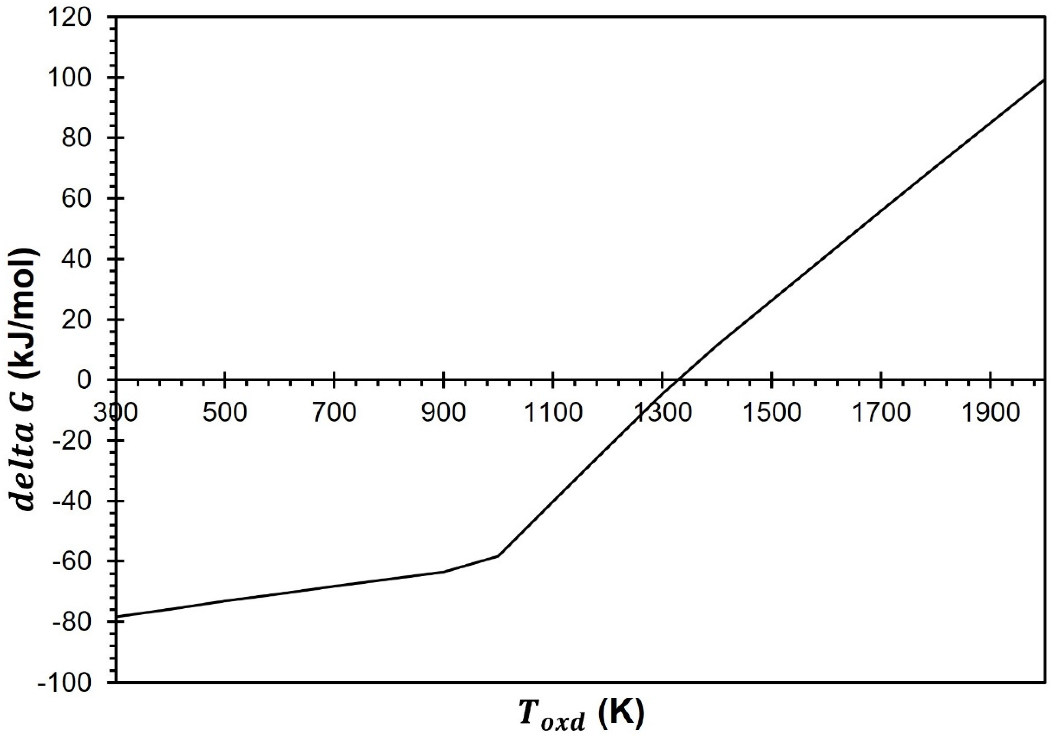
Most studies conduct the CDS at 1000 K, according to the published literature. In addition, as per the delta G analysis (
Figure 4), the CDS for the GeO
2/GeO redox cycle is feasible below 1300 K. Therefore, in this investigation the production of CO is also conducted at
= 1000 K via re-oxidation of GeO. With the help of HEX-1, the inert/O
2/GeO gas mixture (which exits the reduction cell) is cooled from
to
. This cooling process also helps to alleviate the recombination of the gaseous products O
2 and GeO. With the help of the cooling set, gaseous GeO is converted into solid GeO and separates from the mixture of inert and O
2 gases. The energy released during the cooling process is then harnessed to preheat the inert sweep gas, which helps to optimize the overall efficiency of the system. The solid GeO is transported to the oxidation cell where it undergoes a reaction with a surplus amount of CO
2, which is ten times higher than the required amount. This reaction results in the re-oxidation of GeO to GeO
2 and the production of CO through the CDS reaction. Although
varies from 1600 to 2000 K, a constant temperature of 1000 K is applied during the CDS step. Therefore,
remains constant at 239.7 kW.
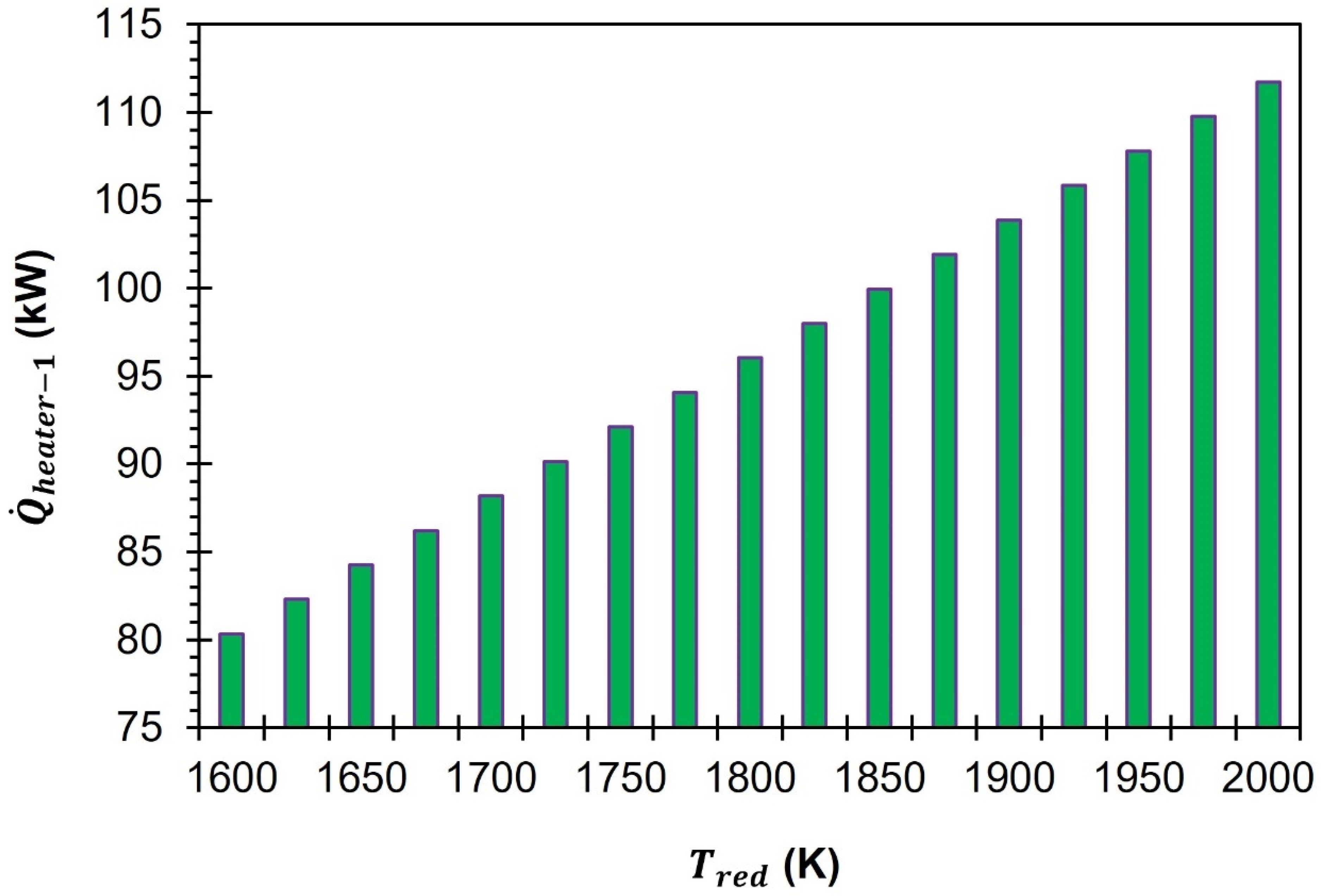
In order to ensure the around-the-clock operation of the GeO
2/GeO-based CDS cycle, it is imperative to recycle the GeO
2 generated in the oxidation cell as the feed to the reduction cell. During the re-oxidation process of GeO, it is maintained at a constant temperature of 1000 K. The resulting GeO
2 is subsequently heated to
with the aid of heater-1. This process ensures that the GeO
2 is adequately heated to the desired temperature to perform the TR step. The data presented in
Figure 5 demonstrate that an increase in
from 1500 K to 2000 K results in a corresponding increase in the heat supply required from heater-1. As the
increases from 1500 K to 2000 K,
rises from 80.3 kW to 113.7 kW.
The oxidation cell generates a gas mixture consisting of unreacted CO2 and CO. This gas mixture is then transferred to separator-2 for further processing. In order to reuse the unreacted CO2 for the CDS reaction, it is necessary to separate it from CO. After separating the CO2 from the CO, the latter is transferred to the fuel cell for the completion of the cycle. Separator-2 is operated at = 400 K. To reach the target temperature of 400 K, the mixture of CO2 and CO gases is cooled down from 1000 K. This cooling process is made possible by HEX-4, which regulates the temperature of the gas mixture before it enters separator-2. is estimated by using Equations (6) to (8) and by using the assumption already mentioned in the previous section. At all , the energy required to separate CO2 and CO remains constant at 71.8 kW. This is because changes to and do not change .
To prepare for the fuel cell, the temperature of the CO is first lowered from 400 K to 298 K. This is achieved by using cooler-1, which releases heat to the ambient environment. As part of the process, the unreacted CO2 (separated from the inert gas) also undergoes cooling, from an initial temperature of 1123 K down to 298 K. This cooling is achieved by passing the CO2 through HEX-3. The fuel cell is a device where a chemical reaction occurs between CO and O2. This reaction is responsible for completing the GeO2/GeO-based CDS cycle, which ultimately leads to the production of CO2.
The CO2 that is generated during the operation of the fuel cell, along with the CO2 separated from the CO, are combined and then moved to the oxidation cell. To ensure the proper functioning of the oxidation cell at 1000 K, a gas-to-gas heat exchanger, HEX-4, and an auxiliary heater, heater-4, are installed in the process. These components work together to effectively heat the CO2 from 298 K to 1000 K, thereby facilitating the oxidation process. In the context of HEX-4, it is noteworthy that the energy that is released during the cooling process of the CO2–CO mixture is effectively harnessed and utilized for the purpose of heating CO2 ( = 0.5). To heat CO2 from 298 K to 1000 K, more energy is required than the energy released during the cooling of a mixture of CO2 and CO gas from 1000 K to 400 K. Therefore, an additional energy of 192.5 kW is provided by heater-4.
To keep the fuel cell running smoothly, it is crucial to maintain a constant flow of O
2. Additionally, the reduction of GeO
2 requires the presence of an inert sweep gas. The mixture of inert gas and O
2, which has been separated from GeO, requires additional separation in order to meet the aforementioned goals. To separate the O
2 from the inert sweep gas, a device called separator-1 (which is explained in detail in
Section 2) is incorporated into the cycle. To separate the high-temperature stream of the inert/O
2 gas mixture, a specialized arrangement similar to an ion transport membrane separation technology is employed in the real process [
36]. As per the findings published in previous studies, the most effective range for the separation of gaseous components through ion transport membranes lies in the temperature range of 1050 K to 1200 K. Therefore, in this study, separator-1 operates at 1123 K. According to the process model illustrated in
Figure 1, in order to achieve
of 1123 K, a mixture of inert gas and O
2 is heated with the aid of three different heating mechanisms: HEX-2, HEX-3, and heater-3 (if necessary).
In the HEX-2 and HEX-3 processes, the energy that is released during the cooling of O
2 and CO
2 is harnessed to heat up the inert/O
2 gas mixture (
= 0.5). According to the calculations, the amount of energy needed to heat the mixture of inert gas and O
2 is significantly greater than the sum of the energy released in the process of cooling O
2 and CO
2. To elevate the temperature of the inert/O
2 gas mixture from 1000 K to 1123 K, it is imperative to have an additional heat energy supply, which can be fulfilled by incorporating heater-3 into the system.
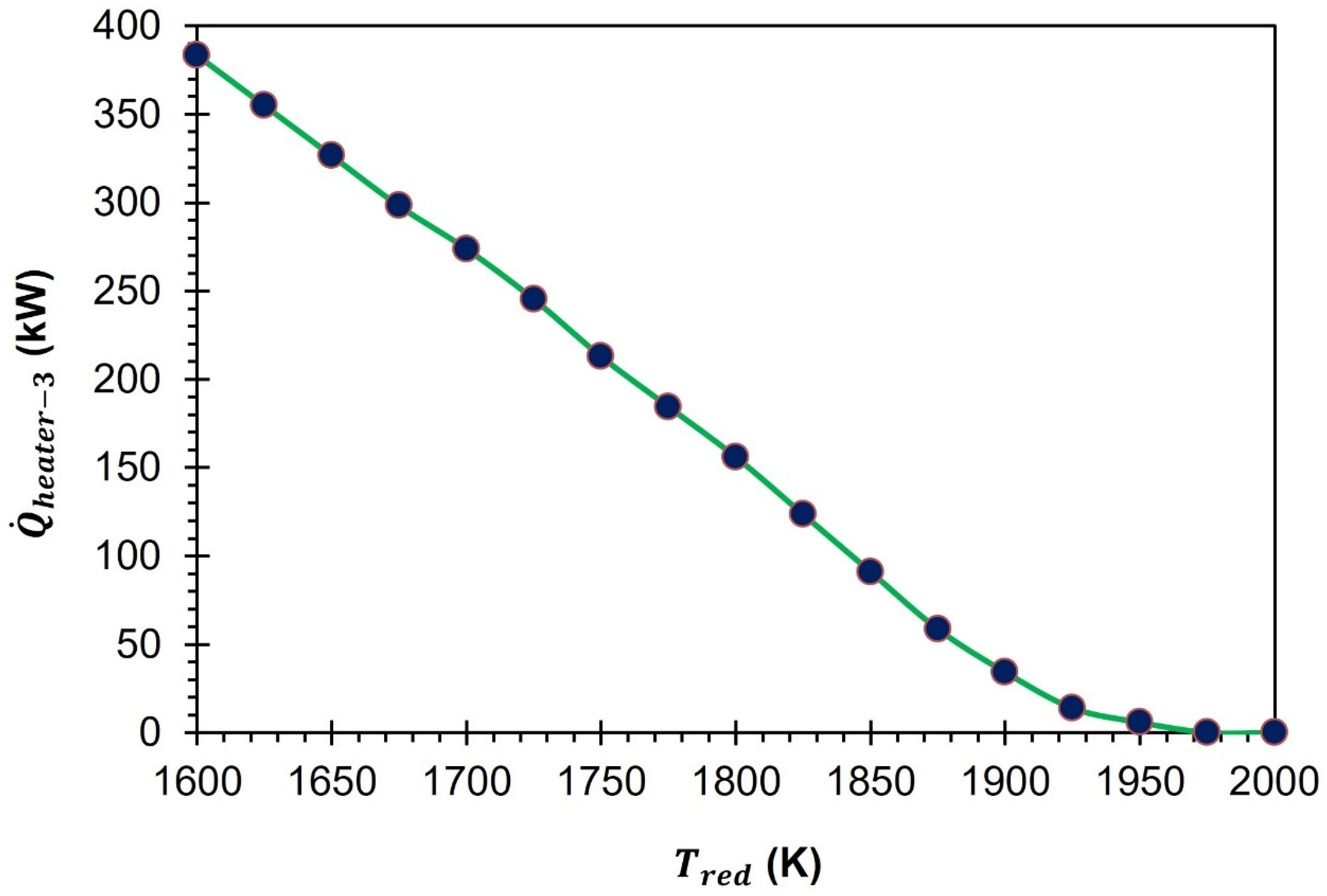
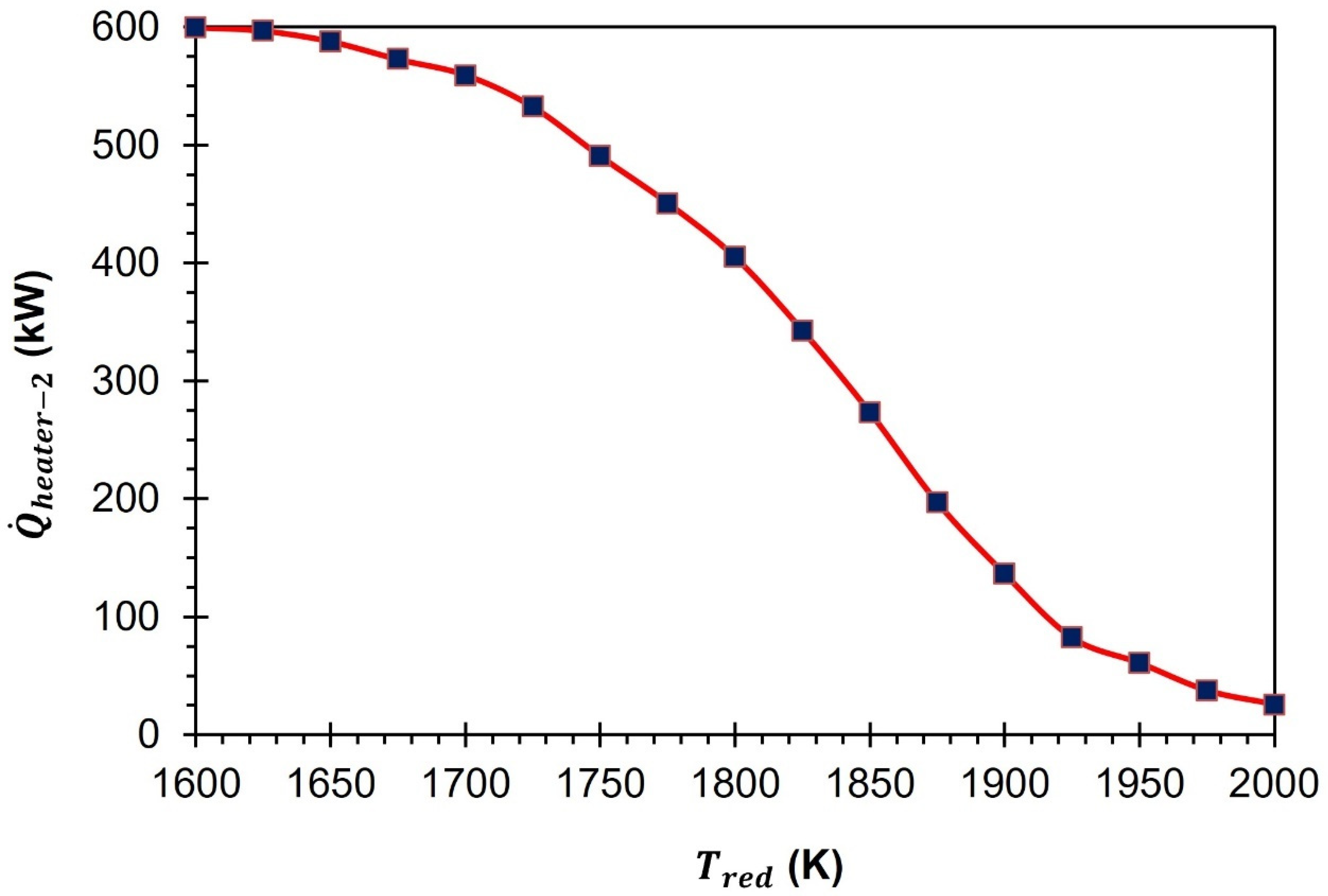
Figure 6 displays the changes in
in response to the increase in
. It is anticipated that a particular pattern will emerge as a higher
will be necessary to attain the full dissociation of GeO at a lower
. To achieve complete dissociation of GeO
2 at a temperature of 1600 K, it is necessary to maintain an
of 100 mol/s, along with
= 383.5 kW. As the
is raised from 1600 K to 1700 K, 1800 K, 1900 K, and 2000 K,
required to achieve 100% reduction of GeO
2 decreases. Specifically,
is reduced to 73 mol/s, 44 mol/s, 14 mol/s, and 4 mol/s, respectively. As a result of the reduced demand for inert gas supply,
drops to 273.8 kW, 156.1 kW, 34.2 kW, and 0 kW, respectively.
Upon reaching a temperature of 1123 K, the gas mixture containing inert gas and O
2 is directed towards separator-1 for further processing. By taking into account the enthalpy of mixing and applying the principles of the second law of thermodynamics,
can be estimated using Equations (16) to (18). Based on the calculations, it appears that
is significantly affected by the quantity of inert sweep gas utilized during the TR step (
Figure 7). In the given scenario, it is observed that at
= 1600 K and
= 100 mol/s, the value of
is recorded as 97.4 kW. However, as
increases to 1800 K and 2000 K,
decreases to 170.3 kW and 97.4 kW. This decrease can be attributed to the reduction in
to 44 mol/s and 4 mol/s, respectively.
Once the process of separating O
2 from the inert sweep gas has been carried out successfully, the purified O
2 is directed towards the fuel cell where it engages in a chemical reaction with CO. In contrast, the inert sweep gas is subjected to further heating until it reaches
and subsequently recycled back into the reduction cell to maintain a continuous process. Within the cycle, there are two components designed to facilitate the heating of the inert sweep gas. Firstly, there is a gas-to-gas heat exchanger, also known as HEX-1. Secondly, there is a supplementary heater, aptly named heater-2, which is ready to provide additional heat to the gas if required. When the amount of energy that is recovered exceeds the amount of energy that is needed, the value for
is considered to be zero. Together, these two components enable efficient and effective heating of the inert sweep gas. The energy released during the cooling of the gaseous mixture of inert gas, O
2, and GeO is repurposed by HEX-1 to heat the inert sweep gas (
= 0.5). As shown in
Figure 8, it can be observed that the highest
is registered at the lowest
. This is due to the requirement of using a substantial amount of inert sweep gas. It is noteworthy that the value of
is reduced by 573.9 kW when
is increased from 1600 K to 2000 K due to the reduction in
from 100 mol/s to 4 mol/s.
It is a well-known fact that heat energy tends to escape from hot surfaces through both conduction and convection. Despite the use of top-notch insulation, such losses cannot be entirely avoided. This implies that a certain amount of heat will always dissipate into the surroundings. In order to ensure accurate analysis in this study, we have taken into account the effects of conduction and convection losses. To do so, as per Equation (26), we have factored in a 20% heat loss from the surface of the reduction cell. This estimation has been derived from the findings of previously published studies on the subject [
37]. As shown in
Figure 7,
decreases from 94.8 kW to 93.0 kW when the
increases from 1600 K to 2000 K.
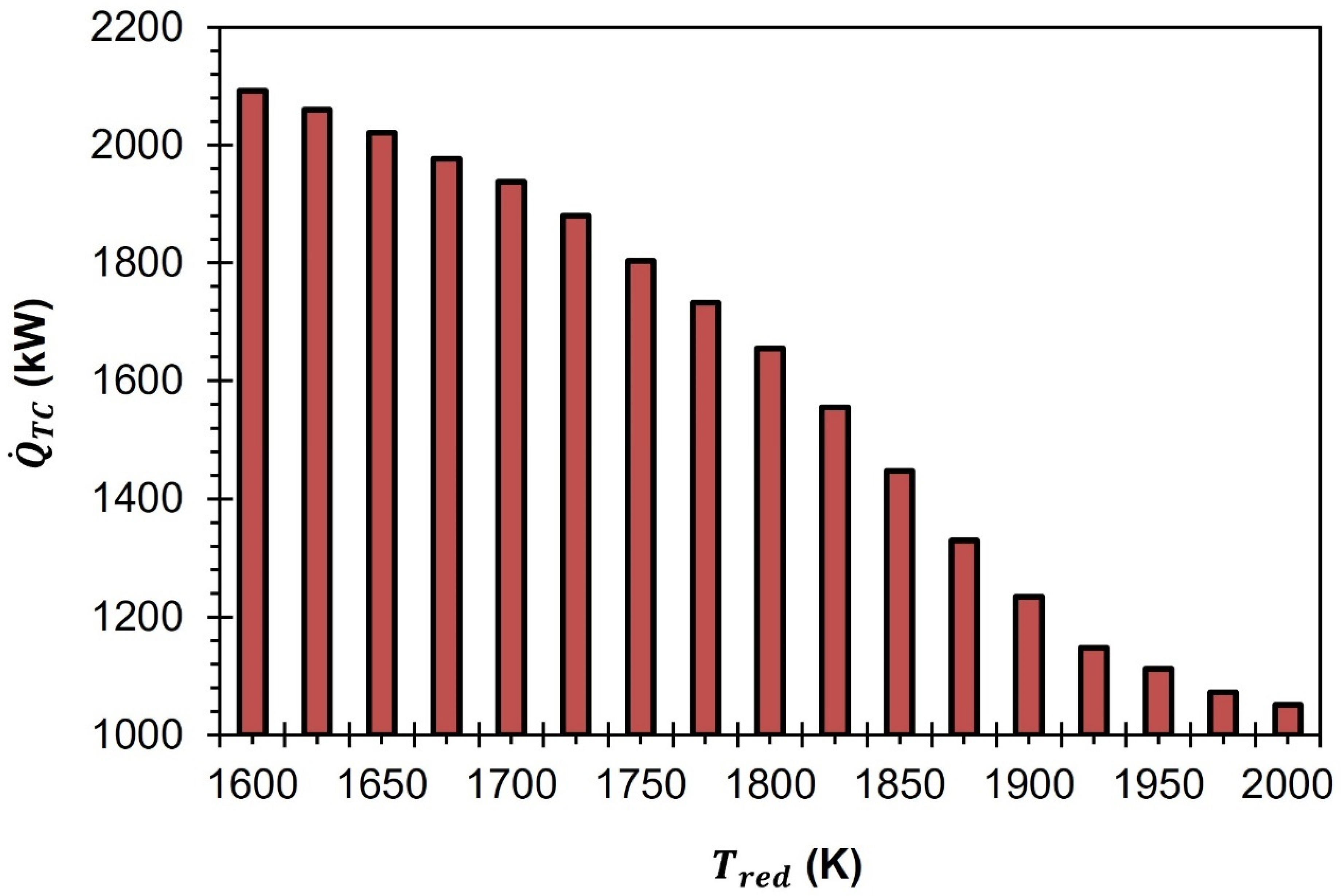
The amount of thermal energy needed to operate the GeO
2/GeO-based CDS cycle (
) can be calculated using Equation (25). This equation takes into account several factors such as the energy required for the reduction reaction, as well as the heaters and separators used in the process. Additionally, any heat losses from the surface of the reduction cell are also considered in the calculation. As per the trends reported in
Figure 9,
decreases as a function of the rise in
. At
= 1600 K,
is equal to 2092.5 kW. As the
increases to 1700 K, 1800 K, 1900 K, and 2000 K,
reduces to 1937.8 kW, 1655.1 kW, 1234.5 kW, and 1050.9 kW, respectively.
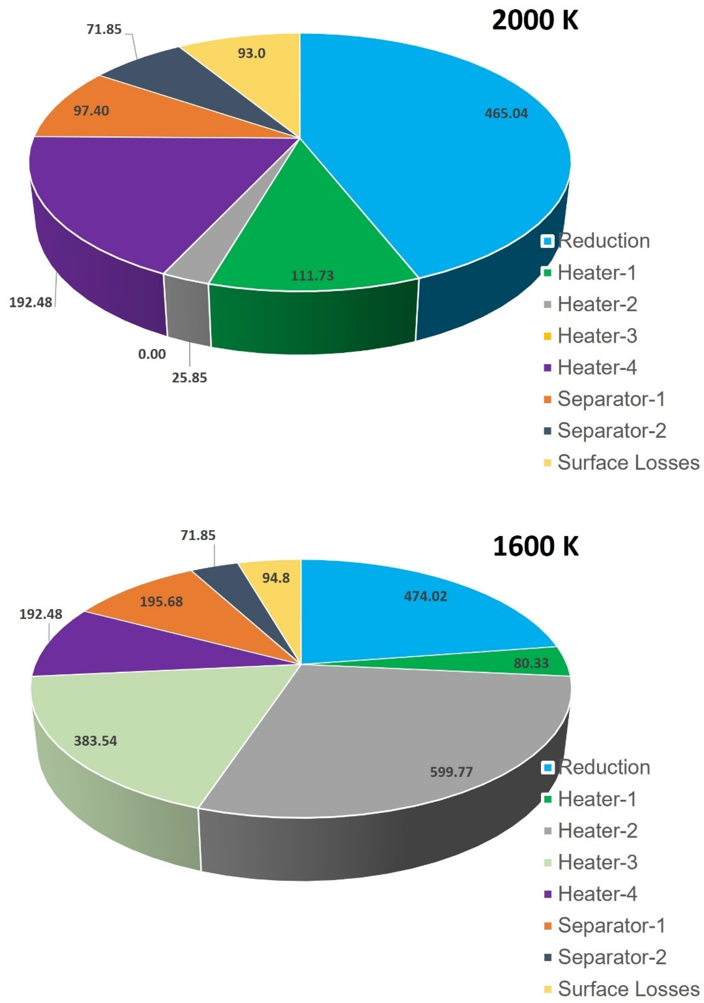
In order to understand why
is higher at lower
, we conducted a comparison of the total thermal energy needed for the GeO
2/GeO-based CDS cycle at two different temperatures: 1600 K and 2000 K (as shown in
Figure 10). The presented results indicate that the higher
at 1600 K than 2000 K is mainly due to the rise in
,
, and
. For instance,
,
, and
are recorded to be higher by 573.9 kW, 383.5 kW, and 98.3 kW, respectively, at 1600 K compared to at 2000 K. As previously noted, in order to sustain the operation of the cycle at a temperature of 1600 K, a considerable amount of 100 mol/s of inert sweep gas is required. This is markedly higher than the
needed at 2000 K, which stands at 4 mol/s. The functions of heater-2 and heater-3 are to increase the temperature of the inert sweep gas in the system. On the other hand, separator-1 is responsible for separating the inert sweep gas and O
2. As, all three units heavily depend upon the inert sweep gas flow rate, the values of
,
, and
are recorded to be higher at 1600 K as compared to 2000 K. In summary, it can be inferred that the primary cause for a higher value of
at lower
is the requirement of an excess inert sweep gas flow rate.
To accurately estimate the total solar energy needed for the GeO2/GeO CDS cycle (), it is important to calculate the efficiency of solar energy absorption (). This efficiency is highly influenced by the , making it a critical factor to consider in the estimation process. Equation (24) is used for the estimation of by keeping = 5.6705 × 10⁻⁸ W/m2·K4, I = 1000 W/m2, and C = 3000 suns constant. The calculations performed indicate that is higher at lower values and as the increases, decreases. For instance, at = 1600 K, = 87.6% and as the increases to 1800 K and 2000 K, reduces to 80.2% and 69.8%, respectively.
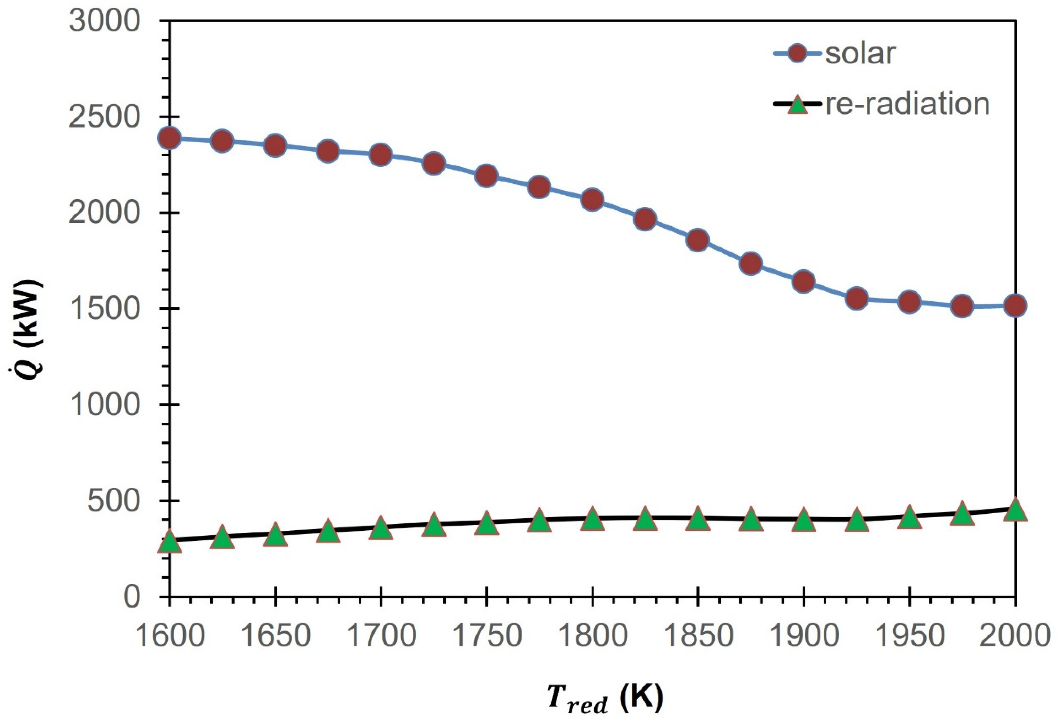
Equations (23) to (27) are used to estimate the total solar energy requirements (
) and re-radiation losses (
) for the GeO
2/GeO CDS cycle. Due to the variations in
as a function of the
,
is observed to be different from
. To put it differently, the
required to achieve a desired outcome must exceed the actual amount needed, as a portion of the energy is lost to the surrounding environment through re-radiation (
Figure 11). At 2000 K,
is equal to 1506.6 kW, which is 455.6 kW higher than
. As
decreases to 1600 K, similar to
,
is also increased to 2388.3 kW due to the rise in
. As shown in
Figure 11,
also increases from 295.8 kW to 432.7 kW due to the rise in
from 1600 K to 2000 K.
The
of the GeO
2/GeO-based CDS cycle is estimated using Equation (22) and presented as a function of
in
Figure 12. The efficiency of converting solar energy into fuel is influenced by several factors. These factors include the quantity of produced fuel, the heating value of the fuel, and the amount of solar energy required to initiate and drive the necessary chemical reactions. The production of CO and its heating value remain constant at 1 mol/s and 283.24 kJ/mol, respectively. However,
can vary due to the change in
as a function of
. The findings presented in
Figure 12 demonstrate that
is 11.9% when
is equal to 1600 K. However, this value increases significantly as the temperature rises. Specifically,
rises to 12.3%, 13.7%, 17.4%, and 19.2%, respectively, when
is raised to 1700 K, 1800 K, 1900 K, and 2000 K. It is interesting to note that
remains steady (19.2%) at 1975 K and 2000 K.
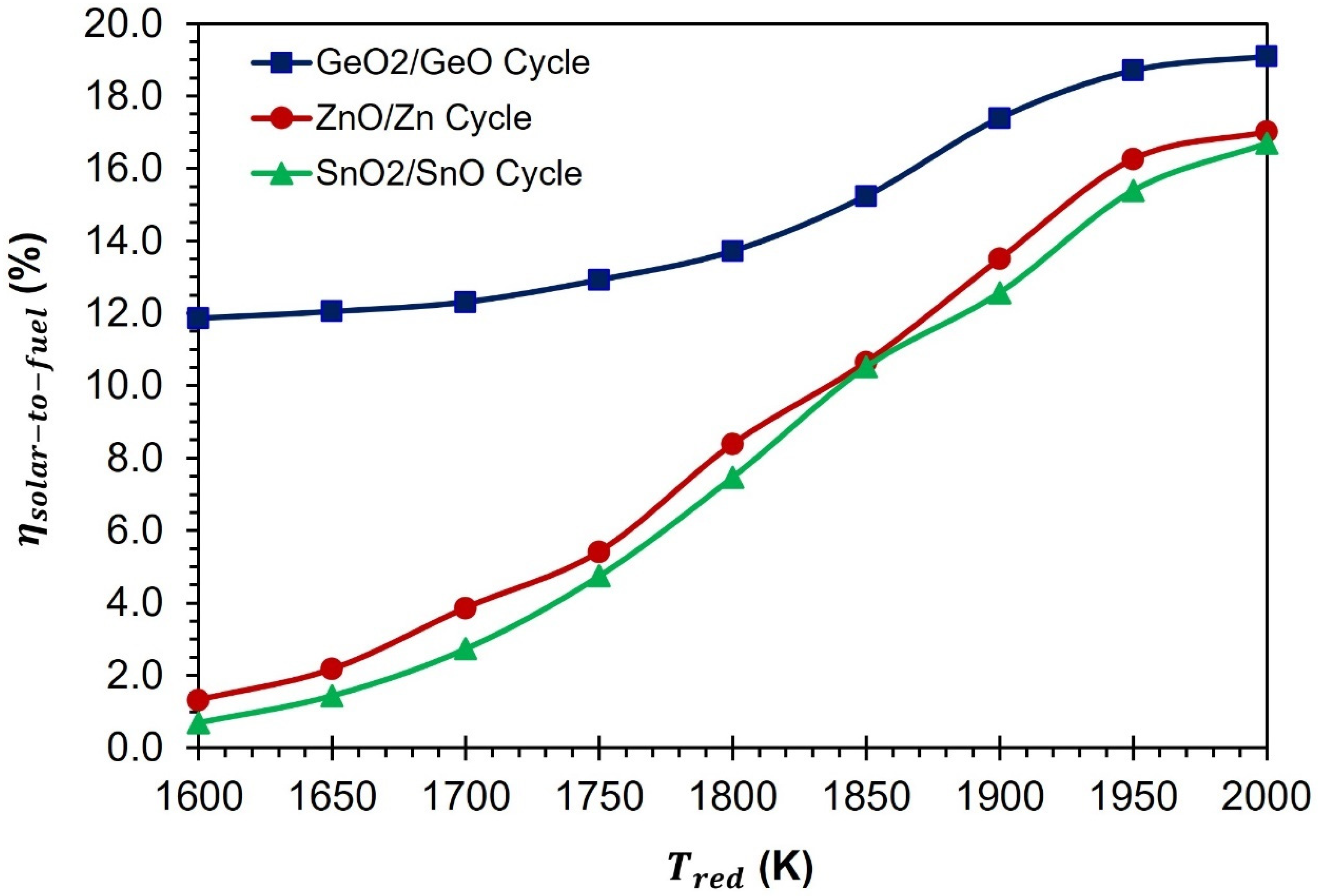
In
Figure 13, a comparison is presented between the CDS cycles of GeO
2/GeO-based, ZnO/Zn-based [
38], and SnO
2/SnO-based materials [
39]. The comparison is based on the values of
. According to the results presented, the
of the GeO
2/GeO cycle is higher than that of the ZnO/Zn and SnO
2/SnO cycles, at all temperatures of TR. At a temperature of 1600 K, the
of the GeO
2/GeO CDS cycle is higher than that of the ZnO/Zn and SnO
2/SnO CDS cycles by 10.5% and 11.2%, respectively. As
increases from 1600 K to 1800 K and 2000 K, the difference between the
of the GeO
2/GeO and ZnO/Zn CDS cycles reduces to 5.3% and 2.1%, respectively. In the case of the SnO
2/SnO CDS cycle, a similar trend was observed. At 1800 K, the difference between the
of the GeO
2/GeO and SnO
2/SnO CDS cycles decreases to 6.2%, and at 2000 K, it decreases to 2.4%. These results confirm that the GeO
2/GeO CDS cycle is more promising than the ZnO/Zn and SnO
2/SnO CDS cycles. The GeO
2/GeO CDS cycle is capable of achieving a reasonably high
of 10% at a temperature of less than 1600 K. On the other hand, the ZnO/Zn and SnO
2/SnO CDS cycles require a higher operating temperature of more than 1850 K to achieve the same level of efficiency.
The impressive performance of the GeO2/GeO CDS cycle can be attributed to the lower requirement of the inert gas supply when compared to the ZnO/Zn and SnO2/SnO CDS cycles. At 1800 K, the inert gas requirement for the GeO2/GeO CDS cycle is lower than that of the ZnO/Zn and SnO2/SnO CDS cycles by 51 mol/s and 89 mol/s, respectively. This reduction in inert gas flow requirement leads to a decrease in heating duty and solar energy requirements, which is reflected in a higher .


 ,
, 


