
Experimental Study on the Flexural Properties of Steel-Fibre-Reinforced Concrete Specimens with Different Heights

Abstract
1. Introduction
2. Three-Point Bending Test
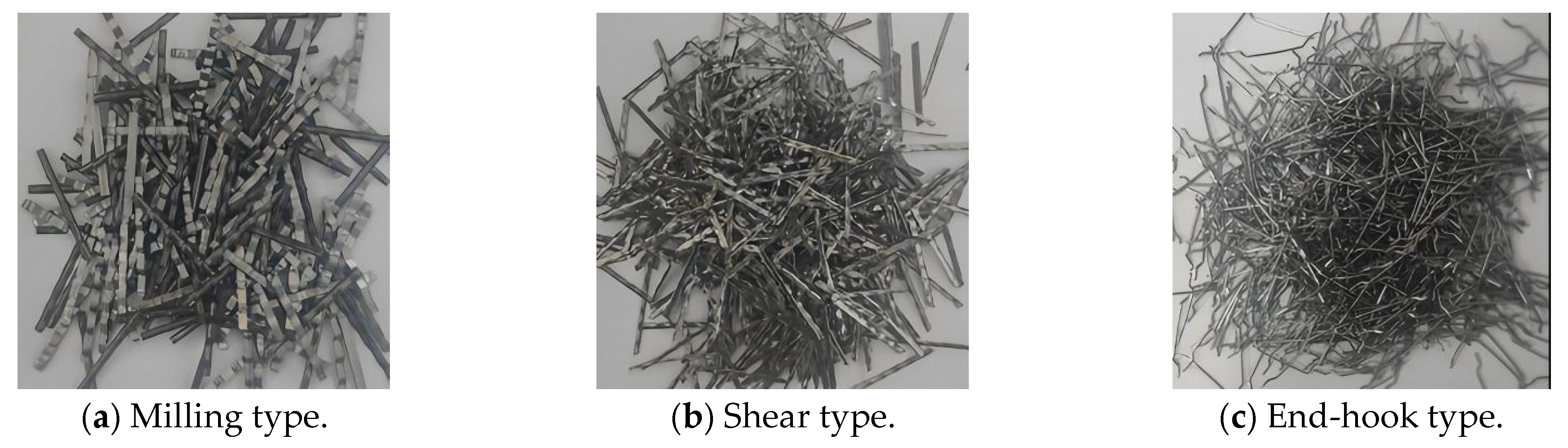
2.1. Specimen Preparation
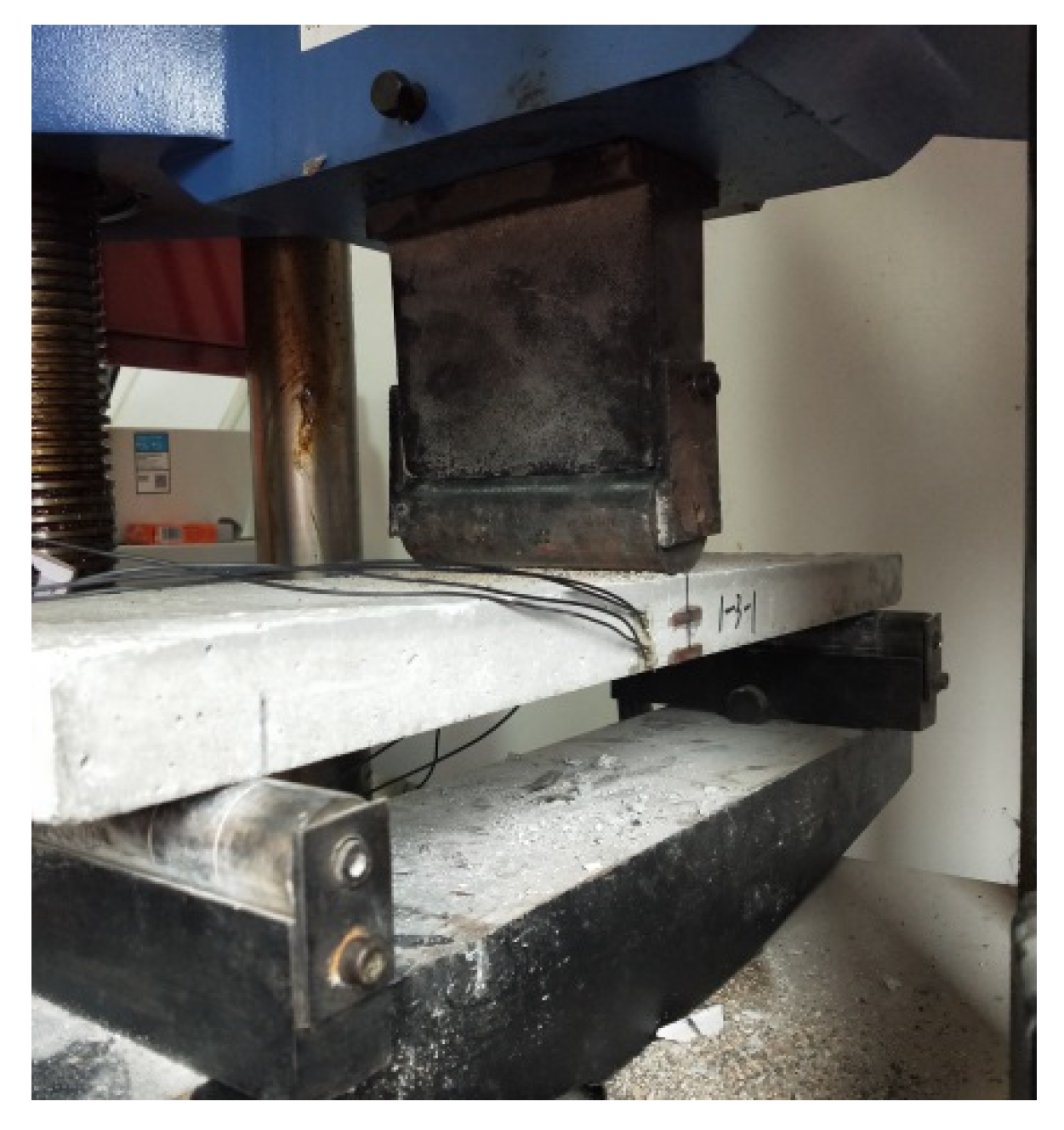
2.2. Bending Test
3. Analysis of the Results
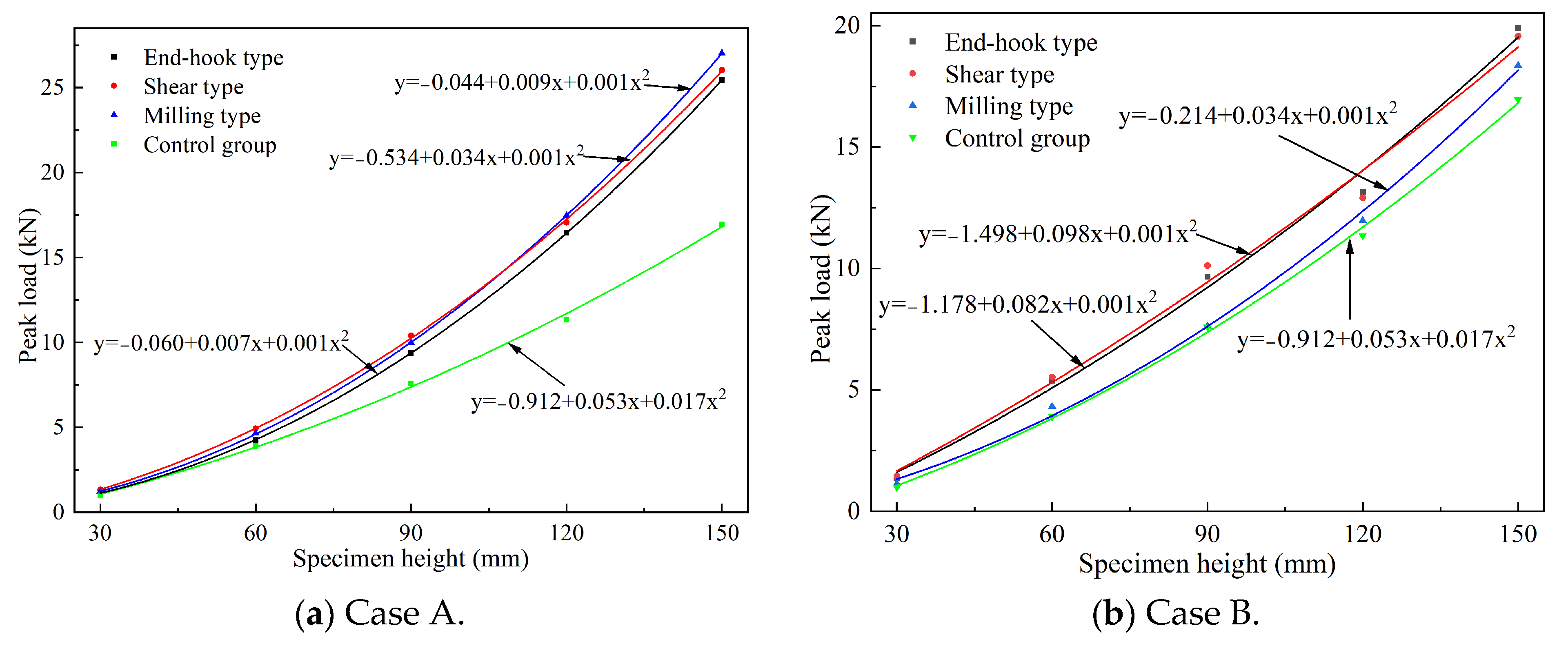
3.1. Peak Load
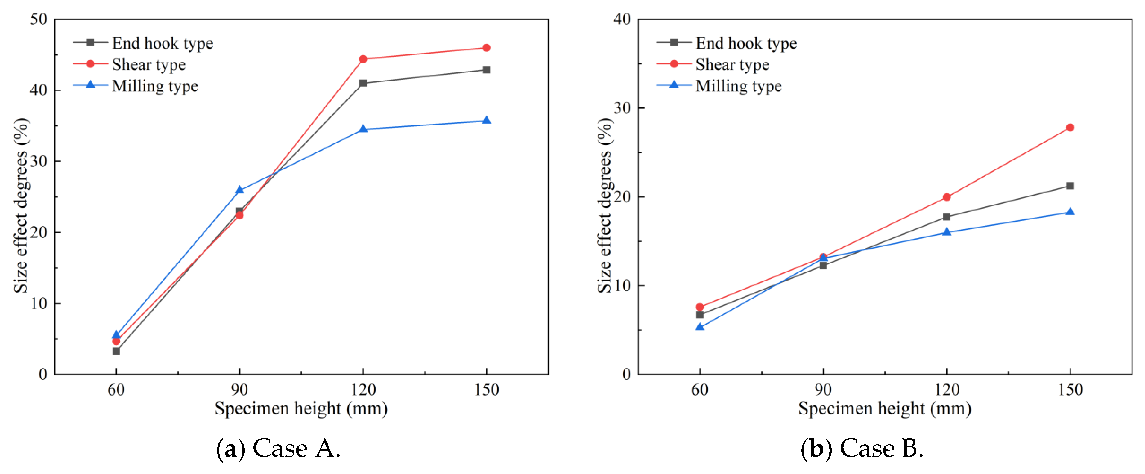
3.2. Effect of Size
3.3. Characteristics of the Load–Displacement Curve
3.4. Strain Characteristics
4. Section Characteristics
4.1. Number of Cross-Section Fibres
4.2. Section Characteristics
5. Conclusions
- (1)
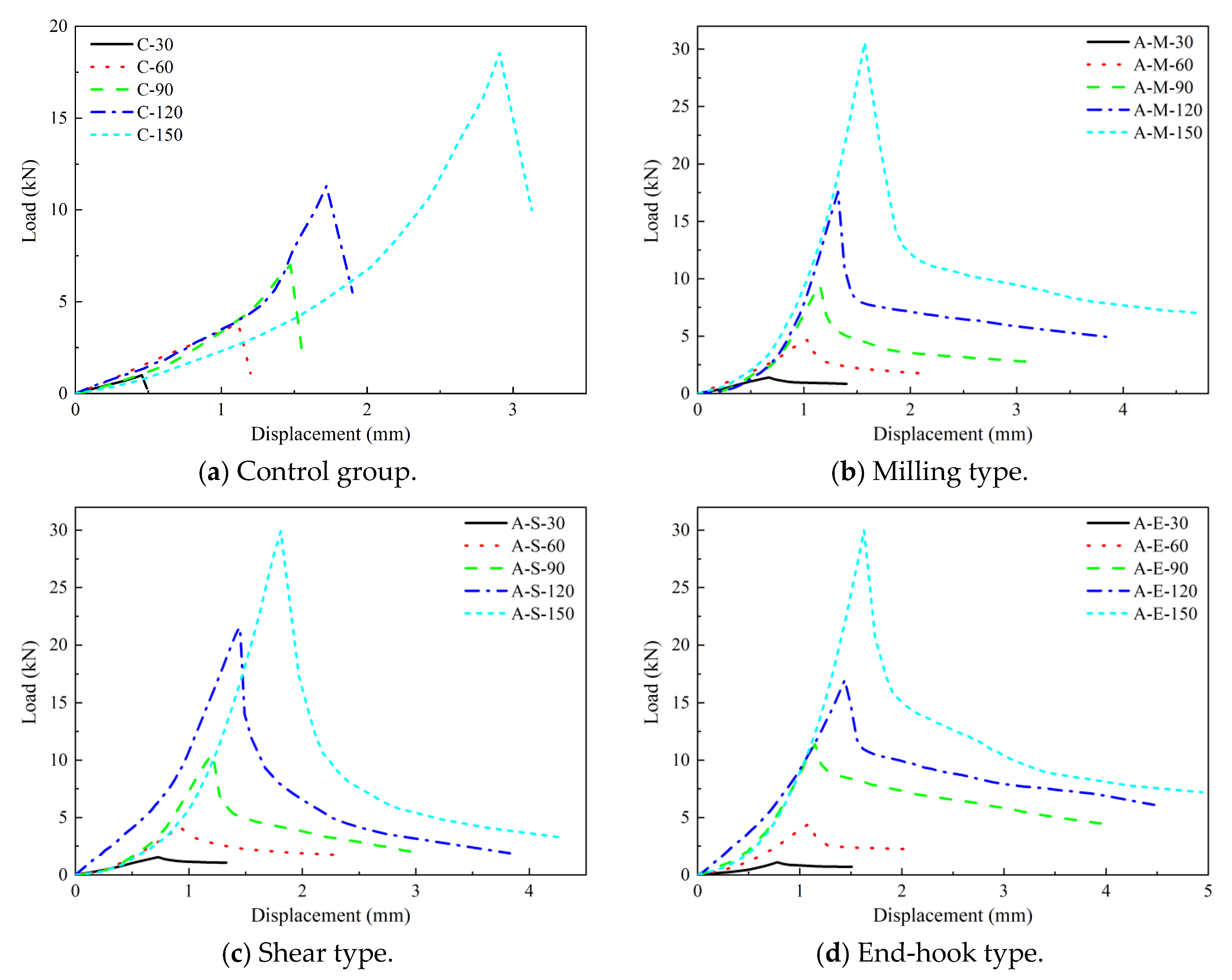
- The addition of three types of steel fibres enhances the peak load of concrete specimens in both case A and case B. In case A, the peak load increases proportionally with the specimen height, exhibiting a linear relationship in the control group. The peak load of specimens with added steel fibres surpasses that of the control group at equivalent specimen heights. The impact of concrete specimen size on flexural strength becomes more pronounced as the specimen height increases in both cases, highlighting the close correlation between peak load and specimen height as well as the method of fibre addition;
- (2)
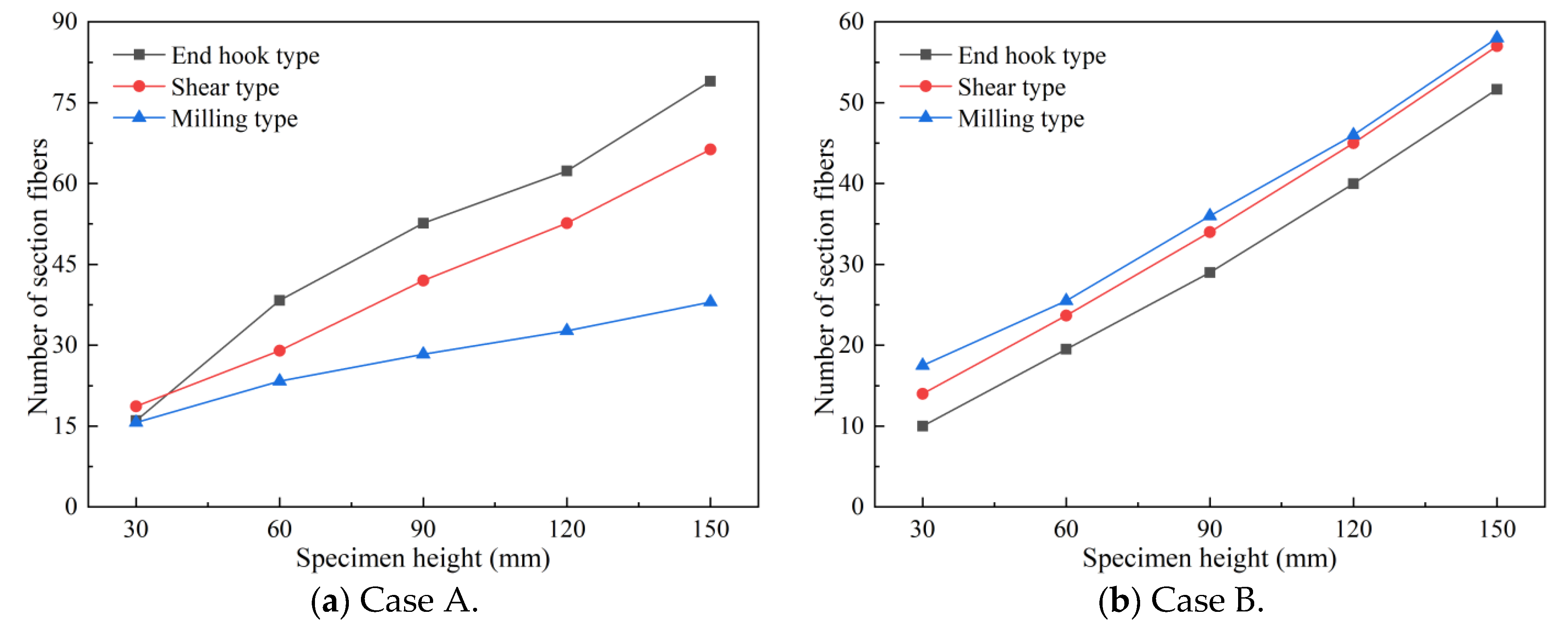
- In case A, the quantity of cross-sectional fibres exhibits a linear increase with the rise in specimen height. Notably, the milling type demonstrates the smallest slope in the linear relationship between the number of cross-sectional fibres and specimen height, followed by the shear type, while the end-hook type exhibits the largest slope. Similarly, in case B, the number of cross-sectional fibres also experiences a linear growth with increasing specimen height, and this linear characteristic is more pronounced than in case A. Furthermore, the three types of steel fibres share a consistent slope in the linear relationship between the number of cross-sectional fibres and specimen height;
- (3)
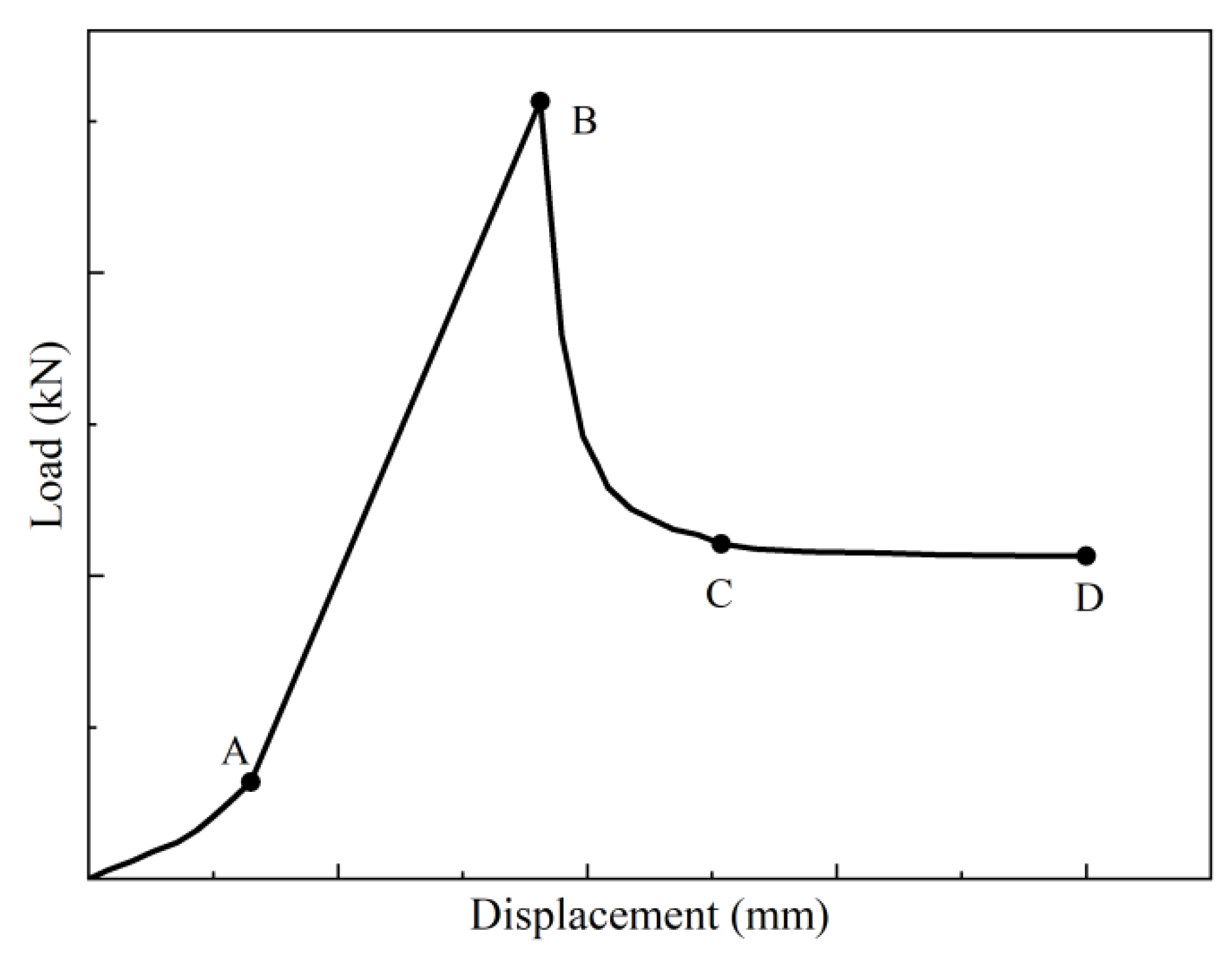
- The load–displacement curve of the specimen can be divided into a slow growth stage (OA stage), a nearly linear growth stage (AB stage), a sharp drop stage (BC stage), and a residual stage (CD stage). The load–displacement curves of the three types of steel fibres at different specimen heights show differences in the CD stage of the load–displacement curve, which basically shows that as the height of the specimen increases, the fluctuation increases. In addition, the load on the CD section in case A first decreases sharply and then gradually slows, while the load on the CD section in case B first decreases sharply and then gradually stabilizes;
- (4)
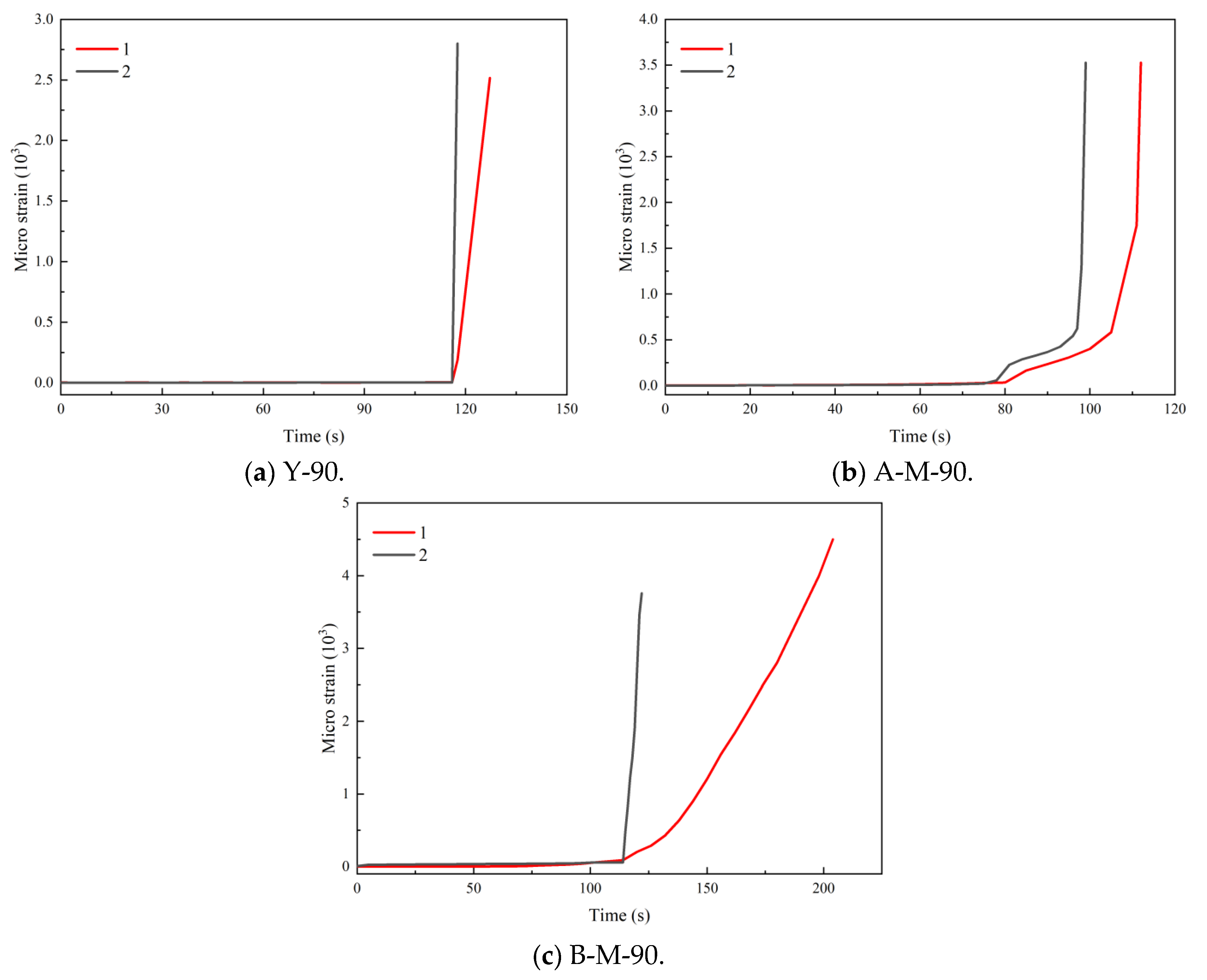
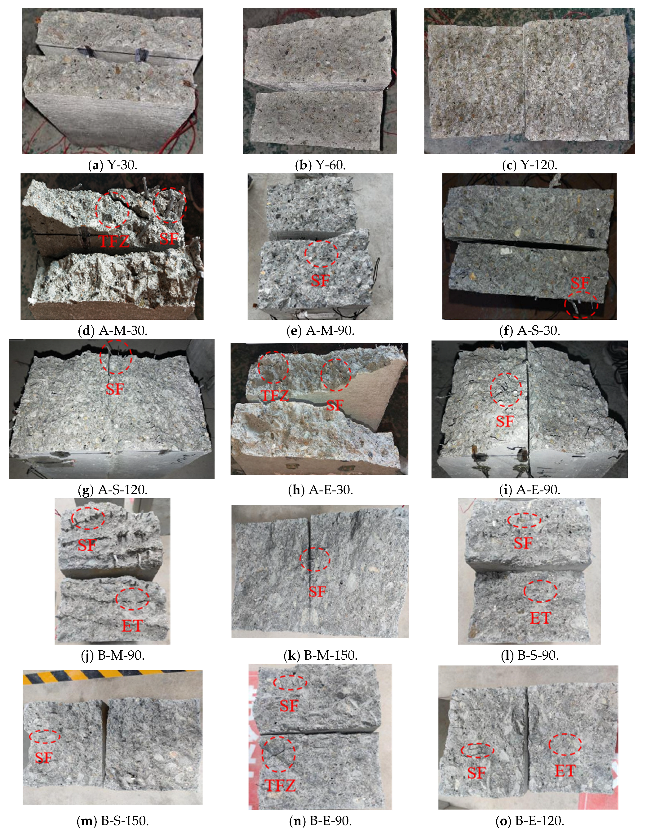
- The control group exhibits distinct brittle failure characteristics, characterized by a flatter failed section and reduced fluctuation as the specimen height increases. In contrast, the specimens with three types of steel fibres in both methodological cases demonstrate a more tortuous development of cracks compared to those without steel fibres. In flexural concrete specimens with lower heights, macroscopic cracks initially emerge in the tensile zone at the bottom, gradually extending to the loading surface with increasing load. Tensile failure areas, densely populated with fibres, may still experience secondary cracks or debris shedding.
Author Contributions
Funding
Institutional Review Board Statement
Informed Consent Statement
Data Availability Statement
Conflicts of Interest
References
- Siddika, A.; Al Mamun, M.A.; Alyousef, R.; Mugahed Amran, Y.H. Strengthening of reinforced concrete beams by using fibre-reinforced polymer composites: A review. J. Build. Eng. 2019, 25, 100798. [Google Scholar] [CrossRef]
- Nili, M.; Azarioon, A.; Danesh, A.; Deihimi, A. Experimental study and modeling of fibre volume effects on frost resistance of fibre reinforced concrete. Int. J. Civ. Eng. 2018, 16, 263–272. [Google Scholar] [CrossRef]
- Yoo, D.Y.; Moon, D.Y. Effect of steel fibres on the flexural behavior of RC beams with very low reinforcement ratios. Constr. Build. Mater. 2018, 188, 237–254. [Google Scholar] [CrossRef]
- Ghanbarpour, S.; Mazaheripour, H.; Mirmoradi, S.H.; Barari, A. The effect of type and volume fraction (VF) of steel fibre on the mechanical properties of self-compacting concrete. J. Eng. Des. Technol. 2010, 8, 247–256. [Google Scholar]
- Zhang, Y.C.; Gao, L.L. Influence of tire-recycled steel fibres on strength and flexural behavior of reinforced concrete. Adv. Mater. Sci. Eng. 2020, 2020, 6363105. [Google Scholar]
- Lee, S.W.; Hassan, R.; Saari, N.; Mohamad, N.M.; Noor, N.I.M. Flexural behaviour of RC beams with steel and polypropylene fibres. J. Phys. Conf. Ser. 2019, 1349, 012071. [Google Scholar] [CrossRef]
- Ni, K.; Shi, Y.X.; Ding, Y.N.; Zhang, Y.G. Influence of Aspect Ratio of Hooked End Steel Fibre on Flexural Behavior of Fibre Reinforced Concrete. Key Eng. Mater. 2015, 629, 560–564. [Google Scholar]
- Jang, S.J.; Yun, Y.J.; Yun, H.D. Influence of fibre volume fraction and aggregate size on flexural behavior of high strength steel fibre-reinforced concrete (SFRC). Appl. Mech. Mater. 2013, 372, 223–226. [Google Scholar]
- Yun, Y.J.; Ahn, K.L.; Lim, W.G.; Yun, H.D. Effects of Steel Fibre Volume Fraction on Compressive and Flexural Behaviors of Alkali-Activated Slag (AAS) Concrete. Appl. Mech. Mater. 2014, 525, 469–472. [Google Scholar]
- Maglad, A.M.; Mansour, W.; Tayeh, B.A.; Elmasry, M.; Yosri, A.M.; Fayed, S. Experimental and Analytical Investigation of Fracture Characteristics of Steel Fibre-Reinforced Recycled Aggregate Concrete. Int. J. Concr. Struct. Mater. 2023, 17, 74. [Google Scholar] [CrossRef]
- Niu, J.G.; Bao, J.; Guo, Y.Z. Experimental Study on the Flexural Tensile Properties of Fibre Reinforced Light-weight Aggregate Concrete. Appl. Mech. Mater. 2013, 341, 1458–1462. [Google Scholar]
- Bawa, S.; Singh, S.P. Flexural performance and toughness evaluation of hybrid steel-polypropylene fibre reinforced self compacting concrete. J. Mater. Eng. Struct. JMES 2018, 5, 333–346. [Google Scholar]
- Visage, E.-T.; Weldon, B.-D.; Jauregui, D.-V.; Newtson, C.-M. Flexural Performance of Ultrahigh-Performance Concrete Developed Using Local Materials. J. Mater. Civ. Eng. 2019, 31, 04019050.1–04019050.12. [Google Scholar] [CrossRef]
- Wang, Y.; Liu, H.; Xi, C.; Dou, G.; Qian, L. Static Analysis of Properties of a Composite Slab Made from Steel Fibres and a Reinforced Foam Concrete. Mech. Compos. Mater. 2019, 55, 535–546. [Google Scholar] [CrossRef]
- Bernal, S.; De Gutierrez, R.; Delvasto, S.; Rodríguez, E.D. Performance of an alkali-activated slag concrete reinforced with steel fibres. Constr. Build. Mater. 2010, 24, 208–214. [Google Scholar] [CrossRef]
- Lee, M.G.; Wang, W.C.; Wang, Y.C.; Hsieh, Y.-C.; Lin, Y.-C. Mechanical properties of high-strength pervious concrete with steel fibre or glass fibre. Buildings 2022, 12, 620. [Google Scholar] [CrossRef]
- Mo, K.H.; Yap, K.K.Q.; Alengaram, U.J.; Jumaat, M.Z. The effect of steel fibres on the enhancement of flexural and compressive toughness and fracture characteristics of oil palm shell concrete. Constr. Build. Mater. 2014, 55, 20–28. [Google Scholar] [CrossRef]
- Mpalaskas, A.C.; Matikas, T.E.; Aggelis, D.G.; Alver, N. Acoustic Emission for Evaluating the Reinforcement Effectiveness in Steel Fibre Reinforced Concrete. Appl. Sci. 2021, 11, 3850. [Google Scholar] [CrossRef]
- Chalioris, C.E. Cracking Diagnosis in Fibre-Reinforced Concrete with Synthetic Fibres Using Piezoelectric Transducers. Fibres 2022, 10, 5. [Google Scholar] [CrossRef]
- Wang, J.; Zhang, M.Z.; Fan, X.C. Experimental Study on the Flexural Fatigue Damage Evolution of Layered Fibre Reinforced Concrete. Key Eng. Mater. 2008, 385, 673–676. [Google Scholar]
- Menna, D.W.; Genikomsou, A.S.; Green, M.F. Compressive and cyclic flexural response of double-hooked-end steel fibre reinforced concrete. Front. Struct. Civ. Eng. 2022, 16, 1104–1126. [Google Scholar] [CrossRef]
- Yun, H.D.; Choi, K.B.; Choi, W.C. Comparative Evaluation of Flexural Toughness of Steel Fibre-Reinforced Concrete Beams. Materials 2023, 16, 3789. [Google Scholar] [CrossRef]
- Yoo, D.Y.; Gohil, U.; Gries, T.; Yoon, Y.-S. Comparative low-velocity impact response of textile-reinforced concrete and steel-fibre-reinforced concrete beams. J. Compos. Mater. 2016, 50, 2421–2431. [Google Scholar] [CrossRef]
- Carrillo, J.; Vargas, J.D.; Arroyo, O. Correlation between flexural-tensile performance of concrete reinforced with hooked-end steel fibres using US and European standards. J. Mater. Civ. Eng. 2021, 33, 04021211. [Google Scholar] [CrossRef]
- Shin, H.O.; Kim, K.; Oh, T.; Yoo, D.-Y. Effects of fibre type and specimen thickness on flexural behavior of ultra-high-performance fibre-reinforced concrete subjected to uniaxial and biaxial stresses. Case Stud. Constr. Mater. 2021, 15, e00726. [Google Scholar]
- Boulekbache, B.; Hamrat, M.; Chemrouk, M.; Amziane, S. Flexural behaviour of steel fibre-reinforced concrete under cyclic loading. Constr. Build. Mater. 2016, 126, 253–262. [Google Scholar] [CrossRef]
- Qiang, Y.; Li, L.; He, Z.P. Experiment research on the steel fibre reinforced concrete in the acid environment. Adv. Mater. Res. 2011, 224, 224–228. [Google Scholar]
- Li, H.Y.; Chen, B.G.; Zhu, K.C.; Gong, X. Flexural Toughness Test and Inversion Research on a Thermal Conductivity Formula on Steel Fibre-Reinforced Concrete Components Post-Fire. Materials 2022, 15, 5103. [Google Scholar] [CrossRef]
- Li, Y.; Yang, E.H.; Tan, K.H. Flexural behavior of ultra-high performance hybrid fibre reinforced concrete at the ambient and elevated temperature. Constr. Build. Mater. 2020, 250, 118487. [Google Scholar] [CrossRef]
- Hakeem, I.Y.; Amin, M.; Abdelsalam, B.A.; Tayeh, B. Effects of nano-silica and micro-steel fibre on the engineering properties of ultra-high performance concrete. Struct. Eng. Mech. 2022, 82, 295–312. [Google Scholar]
- Li, Y.; Li, Y.Q. Experimental study on performance of rubber particle and steel fibre composite toughening concrete. Constr. Build. Mater. 2017, 146, 267–275. [Google Scholar] [CrossRef]
- Teng, S.; Afroughsabet, V.; Ostertag, C.P. Flexural behavior and durability properties of high performance hybrid-fibre-reinforced concrete. Constr. Build. Mater. 2018, 182, 504–515. [Google Scholar] [CrossRef]
- Farhan, N.A.; Sheikh, M.N.; Hadi, M.N.S. Engineering properties of ambient cured alkali-activated fly ash-slag concrete reinforced with different types of steel fibre. J. Mater. Civ. Eng. 2018, 30, 04018142. [Google Scholar] [CrossRef]
- Setiawan, Y.; Tiyani, L.; Murdiyoto, A. Effect of rice husk ash and steel fibres on self-compacting concrte properties. Geomate J. 2023, 25, 130–137. [Google Scholar]
- Caetano, H.; Rodrigues, J.P.C.; Pimienta, P. Flexural strength at high temperatures of a high strength steel and polypropylene fibre concrete. Constr. Build. Mater. 2019, 227, 116721. [Google Scholar] [CrossRef]
- Zhu, H.; Li, C.; Wu, M.; Yan, M.; Jiang, Z. Persistence of strength/toughness in modified-olefin-fibre-and hybrid-fibre-reinforced concrete. J. Test. Eval. 2017, 45, 2071–2082. [Google Scholar] [CrossRef]
- Yuan, T.F.; Lee, J.Y.; Min, K.H.; Yoon, Y.S. Experimental investigation on mechanical properties of hybrid steel and polyethylene fibre-reinforced no-slump high-strength concrete. Int. J. Polym. Sci. 2019, 2019, 4737384. [Google Scholar] [CrossRef]
- Aslani, F.; Liu, Y.N.; Wang, Y. Flexural and toughness properties of NiTi shape memory alloy, polypropylene and steel fibres in self-compacting concrete. J. Intell. Mater. Syst. Struct. 2020, 31, 3–16. [Google Scholar] [CrossRef]
- Islam, S.M.; Hussain, R.R.; Morshed, M.A.Z. Fibre-reinforced concrete incorporating locally available natural fibres in normal-and high-strength concrete and a performance analysis with steel fibre-reinforced composite concrete. J. Compos. Mater. 2012, 46, 111–122. [Google Scholar] [CrossRef]
- Akbari, J.; Abed, A. Experimental evaluation of effects of steel and glass fibres on engineering properties of concrete: Engineering properties of concrete. Frat. Integrità Strutt. 2020, 14, 116–127. [Google Scholar] [CrossRef]
- Yavaş, A.; Birol, T.; Türker, K.; Hasgül, U.; Yazıcı, H. Improvement on Flexural Performance of UHPFRC with Hybrid Steel Fibre. Tek. Dergi 2020, 31, 10379–10397. [Google Scholar] [CrossRef]
- Bajaj, V.; Singh, S.P.; Singh, A.P.; Kaushik, S.K. Flexural fatigue analysis of hybrid fibre-reinforced concrete. Mag. Concr. Res. 2012, 64, 361–373. [Google Scholar] [CrossRef]
- Yoo, D.Y.; Banthia, N.; Kang, S.T.; Yoon, Y.-S. Size effect in ultra-high-performance concrete beams. Eng. Fract. Mech. 2016, 157, 86–106. [Google Scholar] [CrossRef]
- Su, J. The Research on the Size Effect of Concrete Behavior in Compression and Tension; Hunan University: Changsha, China, 2013; pp. 29–34. (In Chinese) [Google Scholar]
- JGJ 55: 2011; Specification for Mix Proportion Design of Ordinary Concrete. China Architecture and Building Press: Beijing, China, 2011. (In Chinese)
- CECS 13: 2009; Standard Test Methods for Fibre Reinforced Concrete. China Plan Press: Beijing, China, 2009. (In Chinese)


| Name of the Material | Cement/kg | Sand/kg | Aggregate/kg | Water/kg |
|---|---|---|---|---|
| Numerical value | 460 | 800 | 915 | 220 |
| Case A | Y | A-E | A-S | A-M | B-E | B-S | B-M | |
|---|---|---|---|---|---|---|---|---|
| Specimen Height | ||||||||
| 30 | 3.33 | 3.80 | 4.44 | 4.08 | 4.64 | 4.83 | 3.81 | |
| 60 | 3.25 | 3.54 | 4.10 | 3.87 | 4.49 | 4.60 | 3.60 | |
| 90 | 3.04 | 3.33 | 3.85 | 3.55 | 3.69 | 3.86 | 3.27 | |
| 120 | 2.39 | 3.13 | 3.55 | 3.43 | 2.84 | 2.79 | 2.60 | |
| 150 | 2.26 | 2.99 | 3.21 | 3.34 | 2.73 | 2.70 | 2.50 | |
| Specimen Failure Diagram | Failure Characteristics | Annotation |
|---|---|---|
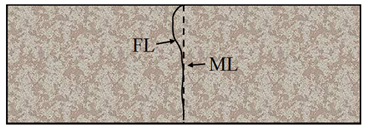 | There are depressions in the upper or lower part of the failure section, and the other end of the failure line is close to the middle line. | FL: Failure line ML: Midline TFZ: Tensile failure zone SF: Steel fibre ET: Extract trace |
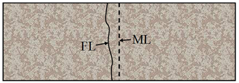 | The failure line is approximately parallel to the midline and has different distances from the midline. | |
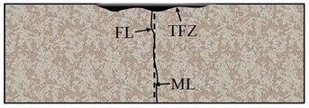 | The failure line is approximately coincident with the midline, and there is a tensile failure zone at the loading end. |
Disclaimer/Publisher’s Note: The statements, opinions and data contained in all publications are solely those of the individual author(s) and contributor(s) and not of MDPI and/or the editor(s). MDPI and/or the editor(s) disclaim responsibility for any injury to people or property resulting from any ideas, methods, instructions or products referred to in the content. |
© 2024 by the authors. Licensee MDPI, Basel, Switzerland. This article is an open access article distributed under the terms and conditions of the Creative Commons Attribution (CC BY) license (https://creativecommons.org/licenses/by/4.0/).
Share and Cite
Yuan, P.; Ren, X.; Xie, Y. Experimental Study on the Flexural Properties of Steel-Fibre-Reinforced Concrete Specimens with Different Heights. Sustainability 2024, 16, 1900. https://doi.org/10.3390/su16051900
Yuan P, Ren X, Xie Y. Experimental Study on the Flexural Properties of Steel-Fibre-Reinforced Concrete Specimens with Different Heights. Sustainability. 2024; 16(5):1900. https://doi.org/10.3390/su16051900
Chicago/Turabian StyleYuan, Peilong, Xianda Ren, and Yongli Xie. 2024. "Experimental Study on the Flexural Properties of Steel-Fibre-Reinforced Concrete Specimens with Different Heights" Sustainability 16, no. 5: 1900. https://doi.org/10.3390/su16051900
APA StyleYuan, P., Ren, X., & Xie, Y. (2024). Experimental Study on the Flexural Properties of Steel-Fibre-Reinforced Concrete Specimens with Different Heights. Sustainability, 16(5), 1900. https://doi.org/10.3390/su16051900