Article

Proactive Emergency Response Strategies for First Responders to Hydrogen Gas Leakages in Vehicles

1
Department of Fire Safety Research, Korea Institute of Civil Engineering and Building Technology, Goyang 18544, Republic of Korea
2
Onstream, Seolleung-ro 112-gil 65, Seoul 06096, Republic of Korea
3
Department of Police Science, Dong-A University, Busan 49236, Republic of Korea
*
Author to whom correspondence should be addressed.
Sustainability 2024, 16(5), 1859; https://doi.org/10.3390/su16051859
Submission received: 8 January 2024 / Revised: 21 February 2024 / Accepted: 21 February 2024 / Published: 23 February 2024
(This article belongs to the Section Sustainable Transportation)

Abstract

:
The widespread use of fossil fuels in automobiles has become a concern, particularly in light of recent frequent natural disasters, prompting a shift towards eco-friendly vehicles to mitigate greenhouse gas emissions. This shift is evident in the rapidly increasing registration rates of hydrogen vehicles. However, with the growing presence of hydrogen vehicles on roads, a corresponding rise in related accidents is anticipated, posing new challenges for first responders. In this study, computational fluid dynamics analysis was performed to develop effective response strategies for first responders dealing with high-pressure hydrogen gas leaks in vehicle accidents. The analysis revealed that in the absence of blower intervention, a vapor cloud explosion from leaked hydrogen gas could generate overpressure exceeding 13.8 kPa, potentially causing direct harm to first responders. In the event of a hydrogen vehicle accident requiring urgent rescue activities, the appropriate response strategy must be selected. The use of blowers can aid in developing a variety of strategies by reducing the risk of a vapor cloud explosion. Consequently, this study offers a tailored response strategy for first responders in hydrogen vehicle leak scenarios, emphasizing the importance of situational assessment at the incident site.

1. Introduction

Amidst the global climate crisis, increasing emphasis is being placed on adopting eco-friendly energy sources. Notably, the transportation sector has been identified as the primary contributor to greenhouse gas emissions, responsible for 28% of emissions that exacerbate global warming [1]. In nations such as the United States and the Republic of Korea, over 90% of automobiles currently operate on fossil fuels, such as gasoline and diesel. Consequently, the promotion of eco-friendly vehicles, including electric, hybrid, and hydrogen models, has gained momentum, leading to significant growth in related industries. For instance, in the Republic of Korea, the registration of eco-friendly vehicles surged from 0.7% in 2014 to 8% by November 2023 [2], with electric and hybrid vehicles dominating this increase. Despite the relatively low penetration rate of hydrogen vehicles, their growth rate is among the steepest. The increasing registration of these vehicles implies that first responders are likely to encounter accidents involving hydrogen vehicles, which present unique challenges compared to traditional internal combustion engine or electric vehicles. According to Korean traffic accident statistics, vehicle-to-vehicle collisions constitute the majority of accidents at 78.8%, followed by vehicle-to-person incidents at 17.3% and single-vehicle accidents at 4.2% [
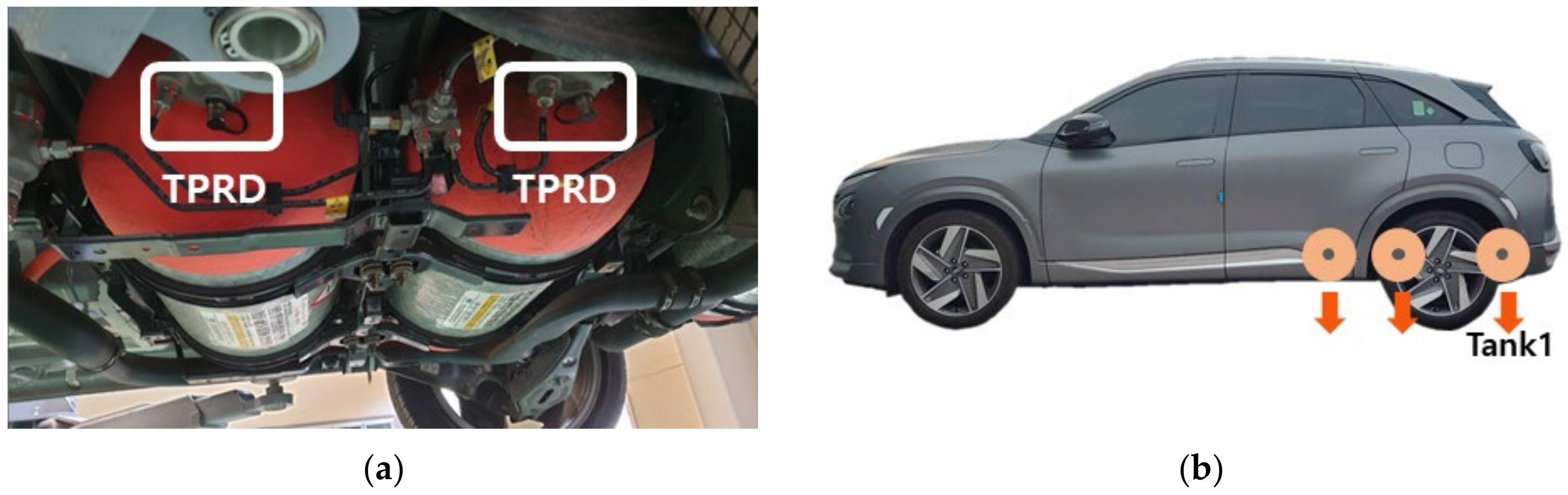
3]. Among vehicle-to-vehicle accidents, side collisions are predominant, accounting for 44.6%, with rear-end collisions being the second most common at 22.9%. Scenarios involving hydrogen vehicles on roads encompass a range of incidents, such as collisions with internal combustion engine vehicles, hydrogen pipe damage leading to leaks, thermally activated pressure relief device (TPRD)-triggered leaks or jet flames due to fires in internal combustion engine vehicles, and container explosions resulting from traffic accidents impacting the TPRD [4].
Regarding the safety of hydrogen as a fuel, several types of accidents involving flammable gases like hydrogen have been documented, including gas leaks, high-pressure jet flames, and explosions resulting from delayed ignition of leaked gas. Gas leaks are particularly critical as they often precede explosions or jet flames [5,6]. Yu et al. delved into the risks associated with hydrogen gas leaking into the interior of a vehicle from a 70 MPa storage container [7]. Their findings indicated that the amount of gas entering the vehicle is significantly influenced by external wind conditions, particularly when sunroofs and windows are open. They observed that at vehicle speeds below 60 km/h, evacuation of occupants is necessary due to insufficient natural diffusion of hydrogen gas to the exterior. Another study investigating vapor cloud formation at hydrogen refueling stations revealed that higher wind speeds increase potential risks by causing rapid and widespread diffusion of hydrogen clouds at lower altitudes [8]. Li et al. also reported that the diffusion length of hydrogen gas leaking from a charging station varies with wind height, noting an increased risk in areas with slower wind speeds near the ground [9]. Cui et al. conducted a numerical analysis to assess the variations in the size of flammable vapor clouds resulting from hydrogen gas leaks in tunnel accidents [10]. The tunnel dimensions were 7.5 m wide, 6.4 m high, and 60 m long. Their study revealed that larger flammable areas were formed when the leak was directed towards the bottom of the tunnel. Notably, ventilation along the length of the tunnel had a significant influence on the formation of vapor clouds. Han et al. found that if hydrogen gas leaks at high pressure inside a tunnel with installed jet fans, the danger zone is smaller when it is discharged at 45° rather than vertically from the floor [11]. Another article indicated that inside a tunnel, the size of the flammable vapor cloud decreases with increasing wind strength yet remains unchanged beyond a certain wind speed [12]. Furthermore, a study investigating the risks in indoor spaces following jet flame generation due to the operation of a TPRD in hydrogen vehicles parked in compartmentalized underground spaces indicated that maintaining the TPRD outlet angle at 45° or less was safer [13]. This orientation minimizes the risk to passengers during rescue operations, as jet flames discharged perpendicular to the floor pose greater hazards. In the case of a leak from a 1/4 inch tube fitting in the hydrogen piping of a hydrogen vehicle, the hydrogen concentration distribution was low at 1–2% vol and highly dependent on the ambient wind [14].
Although research is actively being conducted on the risks associated with hydrogen gas leaks due to accidents or malfunctions in hydrogen vehicles, studies focusing on the effective and safe response strategies for initial responders to such incidents are limited. Experiments on the diffusion extent of hydrogen gas leaking at low pressure from a hydrogen vehicle under varying wind intensities demonstrated that the combustion range exceeded the limit when the wind speed was 10 m/s or higher [15]. Liu and Christopher investigated the optimal approach direction for first responders in the event of a gas leak from a hydrogen vehicle, noting the impact of the wind direction on gas dispersion [16]. Their findings indicated that gas leaked from the lower center of a vehicle dispersed more effectively when the wind blew from the front rather than the side. This characteristic was attributed to the broader side surface of the vehicle, which facilitated the formation of vortices, leading to denser vapor clouds.
In Europe, a perception survey revealed that the general public considers hydrogen energy as safe as other energy sources [17]. A UK survey among first responders about hydrogen vehicle accident response strategies showed that although 60% were aware of the possibility of invisible jet flames, 70% had no experience in responding to hydrogen car accidents [18]. In terms of road safety for hydrogen vehicles, hydrogen storage containers have been identified as presenting a greater danger than fuel cell and piping systems [6]. However, research focusing on leakage scenarios involving the high-pressure vessels commonly used in hydrogen vehicles remains scarce. Section 2 of this paper describes the computational fluid dynamics method and the hydrogen vehicle used in the analysis, and the results of the numerical analysis are presented in Section 3. Section 4 discusses the dangers of flammable vapor clouds and safe accident response strategies based on these results.
In the Republic of Korea, firefighters are tasked with initial rescue and first aid operations. Their responsibilities extend beyond these primary duties to include various site-specific rescue tasks, such as in fire accidents. One of the tools used by firefighters is a portable blower, which helps evacuate smoke from compartments during fire incidents. This study explores the potential application of blowers and suppression methods as safe and effective responses to hydrogen vehicle leaks. This type of investigation is crucial to enhancing the preparedness and safety protocols for first responders in the context of increasing hydrogen vehicle use.

2. Hydrogen Vehicle Gas Leak Model

2.1. Accident Scenarios

The N-Model, a leading hydrogen car in the Korean market, features three type IV hydrogen storage containers, each with a 52.2 L capacity, positioned at the base of the vehicle. These containers collectively hold approximately 6.3 kg of hydrogen, with a total volume of 156.6 L. Arranged in parallel, they extend from the luggage compartment at the rear of the vehicle to beneath the rear seats, with an approximate distance of 500 mm between them. As depicted in Figure 1a, each hydrogen storage vessel is equipped with a TPRD that activates at approximately 110 °C. The design ensures that the discharged hydrogen gas is expelled perpendicular to the ground, as illustrated in Figure 1b.
A hypothetical scenario involving the N-Model was modeled in this study to evaluate effective response strategies to high-pressure hydrogen leaks through the TPRD from the storage container of the vehicle. This vehicle measures 4.67 m in length, 1.86 m in width, and 1.64 m in height. The leak flow rate was calculated using HyRAM, a comprehensive hydrogen safety assessment toolkit. As detailed in Table 1, the calculations were based on a temperature of 20 °C, a container pressure of 70 MPa, a storage capacity of 52.2 L, and a TPRD leak diameter of 1.8 mm. The initial flow rate at the onset of the leak was estimated to be 0.102 kg/s.
In cases where a jet flame emanates from a 1.8 mm diameter nozzle during TPRD operation in a hydrogen vehicle accident, the area posing a direct danger to first responders or evacuees extends to a radius of approximately 5 m from the leak point. Notably, the rear of a vehicle equipped with a hydrogen storage container can experience a severe heat flow rate of 37.5 kW/m2 or higher, leading to significant damage [19]. Consequently, first responders should approach the front of the vehicle from a diagonal direction in accident situations. In accordance with this safety consideration, a blower was positioned at 5 m in this study, diagonally from the hydrogen leak site, to evaluate its effectiveness in mitigating risk in such scenarios.
Smoke is the primary cause of casualties in building fires, necessitating the inclusion of blowers in firefighters’ equipment to expel smoke from buildings. These blowers play a crucial role in smoke management at fire sites, either by increasing internal pressure to force smoke out or by directly extracting it. According to Korean firefighting equipment standards, the flow rate of blowers varies between 16,000 m3/h and 48,000 m3/h, depending on the manufacturer [20]. For this study, a blower with a flow rate of 40,000 m3/h was selected, specifically the ESV230 NEO model, which is a portable electric blower with a 420 mm propeller diameter.

2.2. Numerical Methods

In scenarios where gas leaks from a high-pressure tank into the atmosphere, complex shock waves arise due to the pressure differential between the interior of the tank and the external environment, leading to a choking effect in which the flow rate becomes independent of external atmospheric pressure. This concept has been widely used since Birch et al. first proposed a pseudo-diameter analysis method [21]. Due to the complexity of these phenomena, general numerical analysis methods often fail to converge. Thus, many studies have adopted a pseudo-diameter approach, which simplifies the analysis of choking flow by using principles of mass and momentum conservation. This approach is widely used to analyze leaks and jet flames of various high-pressure gases, including hydrogen and hydrocarbons. Park et al. analyzed the risk by comparing the jet flame behavior at different TPRD installation angles and applied a pseudo-diameter approach to approximate the high-pressure hydrogen leaking from the TPRD [19]. Li et al. proposed a new notional nozzle model and suggested the suitability of the proposed model by comparing its experimental results with those of other hypothetical nozzle models. The Spalart–Allmaras model was used as a turbulence model for computational fluid dynamics (CFD) simulation; the CFD simulations that directly considered the choked flow and the notional nozzle models yielded results analogous to those obtained experimentally [22]. Houf and Schefer suggested a numerical model that can predict leakage patterns not only in existing high-pressure hydrogen leaks but also in regions in which the influence of buoyancy is relatively strong due to leakage at relatively low pressure and compared its results with experimental findings. To simplify the supercritical choked-flow releases, an effective source diameter approach was used [23]. Yu et al. compared the effect of the flame propagation distance of hydrogen jet flames for different heights of barrier walls. To reduce the computational complexity for high-pressure hydrogen leakage of 90 MPa, a notional nozzle approach based on mass and momentum conservation was considered [24].
In this study, we employed CFD techniques to quantitatively analyze the dispersion range of hydrogen gas and vapor clouds leaking at high pressure through the TPRD. To simplify the analysis of the choked flow of leaked high-pressure hydrogen gas, the study utilizes the pseudo-diameter approach. Commercial software ANSYS Fluent 2023 R2 [25] was employed for the CFD analysis, which involves solving nonlinear simultaneous partial differential equations for mass, momentum, energy conservation, and chemical species transport. The general forms of these equations are as follows:
ρ t + · u = S m
Equation (1) represents the mass conservation equation, where ρ denotes the fluid density, u signifies the velocity vector of the fluid, and S m corresponds to the mass generation term [25].
t ( ρ u ) + · ( ρ u u ) = p + · ( τ ) + ρ g + F
Equation (2) articulates the momentum conservation equation [25]. In this context, t symbolizes time, p stands for pressure, and ρ g represents the gravity term. Additionally, F is the generation term due to external forces and τ denotes the stress tensor term.
t ρ E + · u ρ E + p = · ( k e f f T j h j J j + ( τ e f f · u ) ) + S h
Equation (3) outlines the energy conservation equation [25]. Here, k e f f is defined as the sum of k (conductivity) and kt (turbulent thermal conductivity). J j represents the mass diffusion flux of component j, and S h is the generation term attributed to chemical reactions. To analyze turbulence numerically, the study employs the Reynolds averaged Navier–Stokes (RANS) equations. These equations simulate turbulence by decomposing fluid velocity and scalar quantities into average components and turbulence variance components. The governing equations are then formulated for the average components, and the effects of turbulence variance components are computed. In scenarios involving density variations, the RANS equations are interpreted as the Favre averaged Navier–Stokes equations, where density is averaged over time, and velocity and scalar quantities are mass-weighted averages. This analysis utilized the validated SST k ω turbulence model, widely recognized for its application in turbulent flow phenomena. To simulate the flow dynamics through the blower, momentum equivalent to a flow rate of 40,000 m3/h was applied to the area corresponding to the blower fan. This step was performed for each analysis condition, varying according to the orientation of the blower angle.
Figure 2 illustrates the shape and grid structure of a hydrogen vehicle used for the analysis. To examine the distribution of hydrogen gas leaked into the surrounding environment, a numerical analysis space was configured in the form of a rectangular parallelepiped. This space is 100 m in length, 60 m in width, and 25 m in height, originating from the location of the TPRD on the hydrogen container. To focus on the risk as a function of the proximity to the vehicle, an internal area encompassing a radius of 5 m and a height of 3 m from the TPRD nozzle was defined. For computational convergence, the maximum and average skewness values of the generated grids were maintained at 0.84 and 0.16, respectively. Additionally, approximately 1.2 to 1.64 million grids were created in the vicinity of the vehicle using the sweep method.
The study set different conditions for each installation angle of the blower to assess how variations in the position of the blower affect the flammable area during a hydrogen vehicle leak accident. As depicted in Figure 3, the blower angle was defined as clockwise with respect to the leak point and the left side of the vehicle, and the tilt angle was defined as the counterclockwise rotation between the blower and the leak point. The first scenario, Case 1, was established to evaluate the risk in situations where no blower is installed. Given that the safest access point during a jet flame accident is diagonally in front of the vehicle [19], the blower was located at 15° intervals, ranging from 30° to 75° relative to the side of the vehicle; these configurations were designed as Cases 3 to 6. Additionally, Case 2 was introduced to examine scenarios where the blower is not directly aimed at the leak point, involving a 5° counterclockwise bias in the direction of the blower. The specific conditions for these analyses are summarized in Table 2.

3. Modeling Result

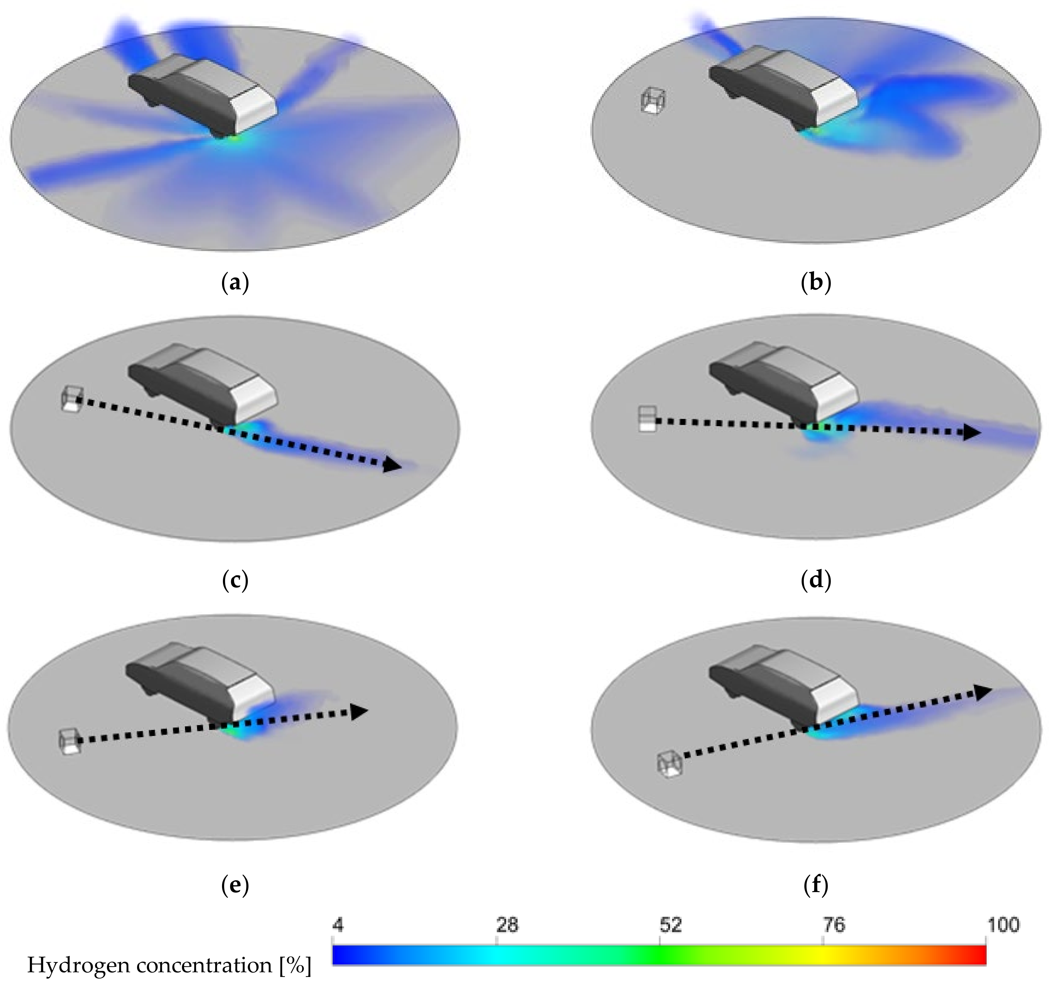
Upon the leakage of high-pressure hydrogen gas, a flammable area is formed around the vehicle as the hydrogen gas, due to its strong linear trajectory, collides with the floor rather than rising buoyantly, as illustrated in 
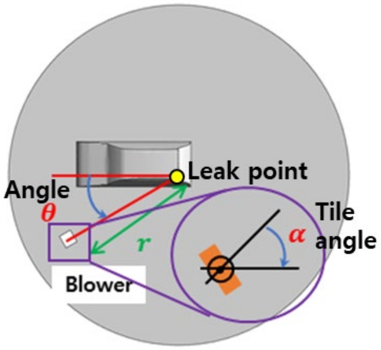
Figure 4a. Given the low specific gravity of hydrogen gas, the concentration is predominantly high near the floor and then gradually diffuses upwards, becoming less dense in the upper layers. If the blower is not pointed directly at the leak point, as depicted in Figure 4b, a relatively large flammable area is formed on the opposite side of the vehicle. As presented in Figure 4c–f, when the blower angle is varied from 30° to 75° at 15° intervals, the flammable area decreases rapidly and spreads in the direction of the wind from the blower. When the blower angle is 45°, as shown in Figure 4d, the diffusion of hydrogen gas is relatively slow. This phenomenon is attributed to the vortex created by the blower wind hitting the wheels of the vehicle.
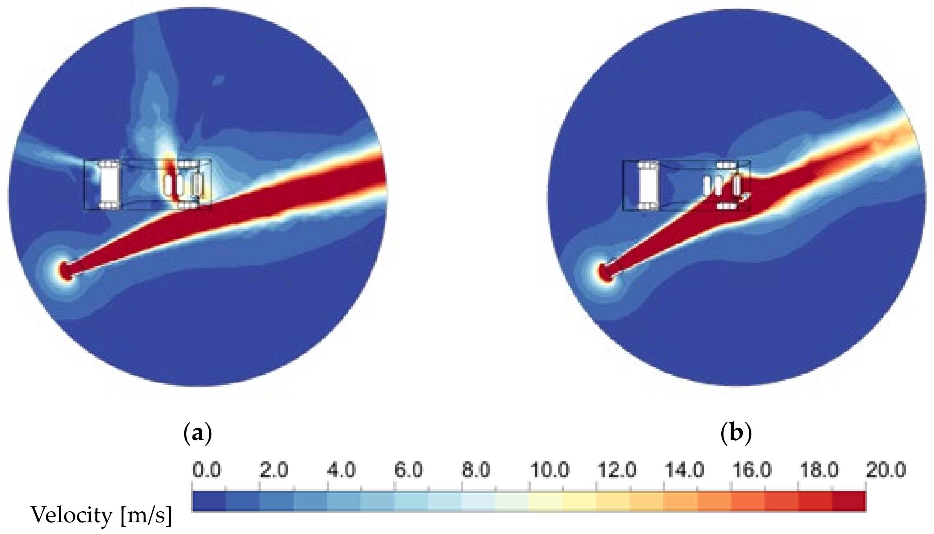
Figure 5 shows the velocity field of the center section of the blower for Cases 2 and 3. Due to a difference in the blower tilt angle of 5°, Case 3 exhibits a high-velocity field of more than 20 m/s around the TPRD, whereas Case 2 shows a high-velocity field outside the vehicle. The difference in the blower angle and the geometric effect caused by the tires mean that the hydrogen gas released from the TPRD in Case 2 is not effectively dispersed by the blower. Consequently, Case 2 exhibits a flammable area approximately 10 times larger than that in Case 3.
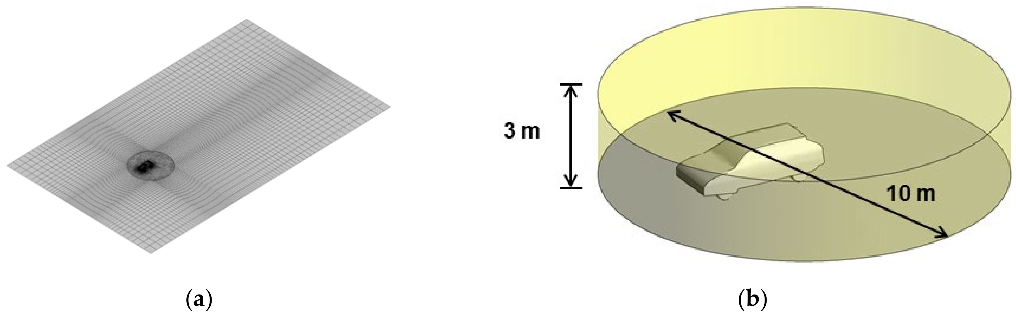
Table 3 presents the size of the flammable vapor cloud for different cases involving the blower, within the specified internal area (radius of 5 m and height of 3 m from the TPRD nozzle). The diffusion of hydrogen gas is the most extensive when the blower angle is 30°, followed by 60°, 75°, and 45°. Marginal differences exist between these angles, with the reduction in diffusion being approximately 90% compared to not using the blower. In contrast, Case 2, where the direction of the blower is misaligned by 5° from the leak point, exhibits a flammable area 10 times larger than that in Case 3 with the same blower angle, and 43% less than that in Case 1, where no blower was used. Therefore, accurately identifying the leak point is crucial when employing a blower in response to a hydrogen gas leak incident.

4. Discussion

4.1. Risks at Hydrogen Leak Sites Posed by Flammable Vapor Clouds

Hydrogen gas is characterized by a broad combustion range and a low ignition energy threshold, significantly elevating the risk of vapor cloud explosions (VCEs). The threshold for eardrum rupture, a critical marker for direct human injury in explosion incidents, is 13.8 kPa [26]. Utilizing a fitting model derived from experimental data on open-air hydrogen explosions [27], the pressure at a distance of 0.5 m was calculated, considering a 4% hydrogen gas concentration, which is the minimal flammable level, and the proximity of first responders to an accident vehicle.
In Case 1, where no blower was used and the vapor cloud volume reached 17.7 m3, a VCE would generate a pressure of 27.1 kPa, posing a substantial risk of bodily harm. Similarly, in Case 2, with a vapor cloud of 10.13 m3, overpressure of 18.9 kPa was predicted, which could also lead to human injury. However, in scenarios where the vapor cloud volume was approximately 1 m3, the resulting pressure was approximately 9.9 kPa, remaining below the human injury threshold. These findings suggest that the use of blowers in early response to hydrogen leaks can effectively mitigate direct harm to humans, emphasizing the importance of such equipment in managing the risks associated with hydrogen vehicle accidents.

4.2. Accident Response Measures for First Responders

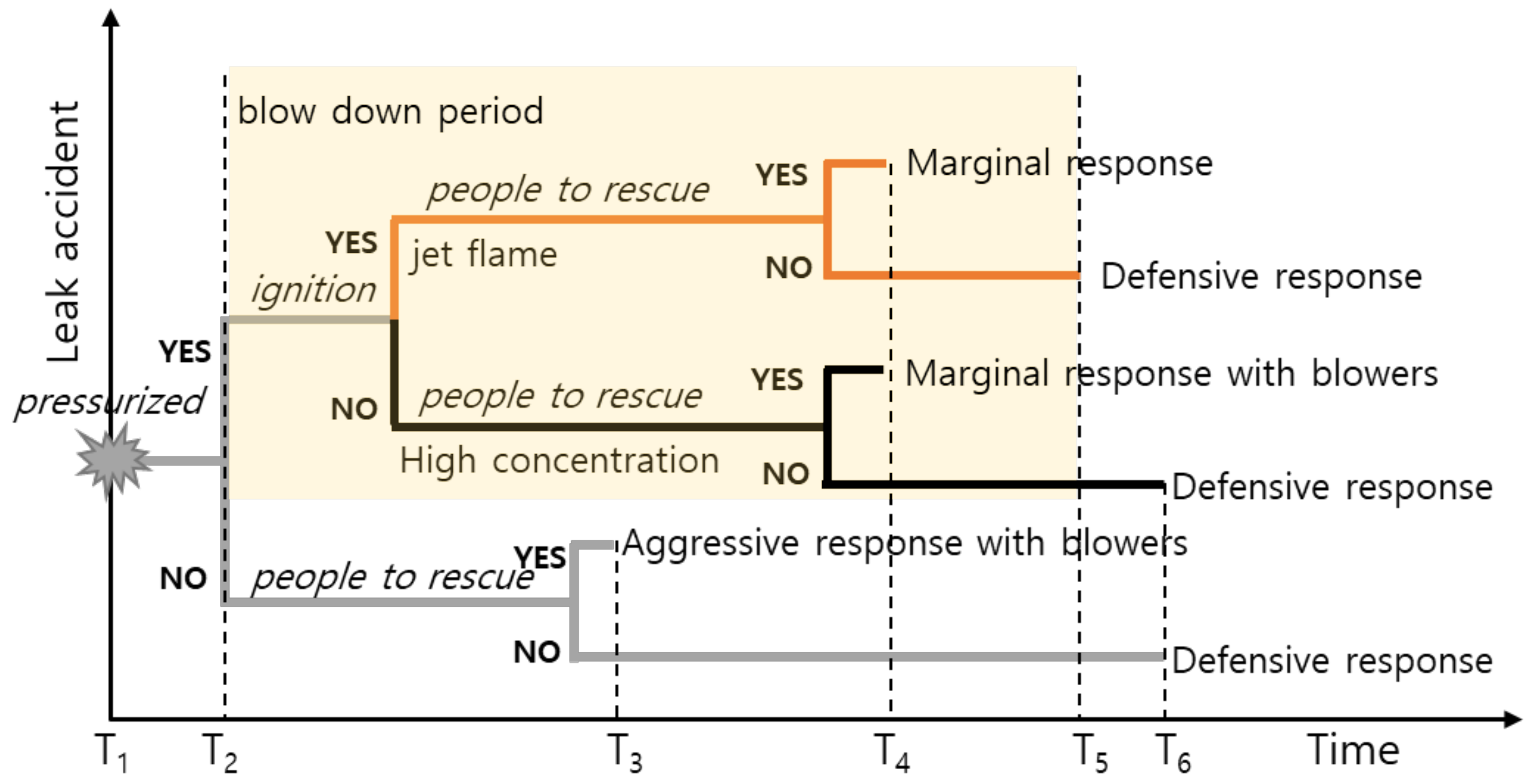
At an accident scene, determining the appropriate response strategy necessitates careful consideration of various factors, including site safety, the presence of individuals requiring rescue, and the potential that the incident will spread to surrounding areas. The response strategies for hydrogen vehicle leaks should be adapted to the specific circumstances encountered at the site, and they can be categorized into aggressive, marginal, and defensive responses. The aggressive strategy is suitable when rescue is urgently necessary at the expense of the first responder, or when the risk of the incident is relatively high, necessitating immediate rescue. The marginal strategy is adopted in situations where a strong fire extends to nearby combustibles or when access is hindered, necessitating some damage acceptance while effectively mitigating risk factors. The defensive strategy is applicable when no additional rescue targets exist, such as in scenarios where the driver autonomously exits the vehicle immediately after a hydrogen car accident. Additionally, this approach is suitable when the risk of the incident spreading to nearby areas is low due to light traffic. It involves safely approaching the site to clear debris once the hydrogen has been completely discharged or burned while simultaneously controlling the accident site and monitoring air gas concentrations.
In cases where hydrogen gas leaks under high pressure following a hydrogen vehicle accident, a large amount of hydrogen gas will discharge at high pressure or ignite into a jet flame, as shown in Figure 6. When hydrogen gas leaks from a 52.2 L storage tank at 70 MPa through 1.8 mm nozzles, the emission rate decreases to 50% within 10 s and 10% within 40 s. Although the discharge duration extends with larger tank capacities, a 50 L hydrogen storage container typically requires no more than 150 s for complete gas discharge [6]. After the rapid release of hydrogen gas, depicted from T2 to T5 in Figure 6, during which the risk is significantly reduced, a defensive strategy can be employed to respond while preventing secondary damage; however, if an urgent need to save lives exists, a marginal response is required.
In a jet flame incident, first responders should take additional insulation measures to complement a fireproof suit, considering the brief duration of intense jet flames. As multiple hydrogen storage vessels are usually involved, rescue operations should be conducted considering the sequentially activated flames. In the case of a high-pressure hydrogen gas leak, the marginal strategy can only be selected when using blowers, as it creates a vapor cloud that can pose a risk to first responders. As indicated by the modeling results, utilizing a blower can mitigate the risk during the blow-down phase of high-pressure hydrogen leakage. Therefore, using a blower actively starting from T2 is crucial. Responding after the hydrogen gas has sufficiently dispersed is safer (T6 in Figure 6) when blowers are not available. As a low-pressure hydrogen gas leak does not produce a damaging vapor cloud [14], an aggressive strategy can be employed if rescuers are present. However, in semi-enclosed spaces, such as tunnels or underground parking garages, where the risk increases, a blower should be used.
In situations where hydrogen gas leaks at high pressure from a storage container, noise levels exceeding 100 dB are generated, increasing with storage pressure [28]. At accident sites with high-pressure gas leaks, excessive noise can hinder the determination of the location of the leak. Visualization can be performed with an acoustic imaging device that shows the high noise area, indicating the point of origin of the leak. The modeling results demonstrate that if the blower is not directed towards the leak, effective diffusion of hydrogen gas is challenging, potentially resulting in vapor cloud formation on the opposite side of the vehicle. To respond safely to hydrogen vehicle accidents, the active use of innovative equipment, such as acoustic imaging devices, is essential.

5. Conclusions

The transportation sector has been identified as a major contributor to global greenhouse gas emissions, with fossil fuels powering over 90% of the current automotive fleet. This has led to increased promotion of eco-friendly vehicles, particularly hydrogen cars, whose numbers have seen a significant rise. However, most first responders are not experienced in handling hydrogen vehicle accidents, highlighting the necessity for safe and effective response strategies. In this study, we examined the effectiveness of blowers in mitigating high-pressure gas leaks from hydrogen vehicles. The results revealed that despite hydrogen gas rapidly dispersing due to its low vapor density, leaked gas under high pressure can still form vapor clouds significant enough to pose a risk to human safety. The study demonstrated that positioning the blower 5 m from the leak point, a distance that shields first responders from unexpected jet flames, is effective. To enhance the diffusion of hydrogen gas, aligning the blowing direction with the leak point rather than adjusting the blower angle is crucial. In less congested areas or situations without additional rescue requirements, the study recommends adopting a defensive strategy to minimize damage spread and protect the surrounding area. Conversely, in scenarios requiring immediate rescue efforts, measures such as using blowers or additional insulation are suggested, taking into account the duration of high-pressure gas or jet flame leaks. Future research will need to continue exploring the types of vehicles and assessing the applicability of blowers in semi-enclosed spaces, such as tunnels and underground parking garages, to develop protocols for safely and effectively responding to hydrogen vehicle accidents.

Author Contributions

Conceptualization, B.P. and O.K.L.; methodology, O.K.L.; software, J.W.K.; validation, J.W.K., Y.K. and B.P.; formal analysis, B.P.; investigation, J.W.K.; data curation, Y.K.; writing—original draft preparation, B.P.; writing—review and editing, O.K.L.; visualization, B.P.; supervision, O.K.L.; project administration, B.P.; funding acquisition, B.P. All authors have read and agreed to the published version of the manuscript.

Funding

This research was funded by the National Fire Agency, grant number 20019150.

Institutional Review Board Statement

This study did not require ethical approval.

Informed Consent Statement

Not applicable.

Data Availability Statement

Data are contained within the article.

Conflicts of Interest

Author J. W. Kim was employed by the company Onstream. The remaining authors declare that the research was conducted in the absence of any commercial or financial relationships that could be construed as a potential conflict of interest.

References

  1. United States Environmental Protection Agency (EPA). Sources of Greenhouse Gas Emissions. Available online: https://www.epa.gov/ghgemissions/sources-greenhouse-gas-emissions (accessed on 20 November 2023).
  2. Ministry of Land, Infrastructure and Transport (MOLIT). Total Registered Motor Vehicles, MOLIT Statistics System. Available online: https://stat.molit.go.kr/portal/cate/statView.do?hRsId=58 (accessed on 3 December 2023).
  3. Korea Road Traffic Authority (KoROAD). Traffic Accident Analysis System. Available online: https://taas.koroad.or.kr/ (accessed on 2 December 2023).
  4. Park, B.; Kim, Y.; Lim, O.K. Development of Accident Scenarios for Hydrogen Refueling Station and Fuel Cell Vehicle. J. Auto-Vehicle Saf. Assoc. 2023, 15, 27–34. [Google Scholar] [CrossRef]
  5. Zhang, X.; Qiu, G.; Wang, S.; Wu, J.; Peng, Y. Hydrogen Leakage Simulation and Risk Analysis of Hydrogen Fueling Station in China. Sustainability 2022, 14, 12420. [Google Scholar] [CrossRef]
  6. Sun, K.; Li, Z. Development of Emergency Response Strategies for Typical Accidents of Hydrogen Fuel Cell Electric Vehicles. Int. J. Hydrogen Energy 2021, 46, 37679–37696. [Google Scholar] [CrossRef]
  7. Yu, X.; Wang, C.; He, Q. Numerical Study of Hydrogen Dispersion in a Fuel Cell Vehicle under the Effect of Ambient Wind. Int. J. Hydrogen Energy 2019, 44, 22671–22680. [Google Scholar] [CrossRef]
  8. Xie, L.; Rong, Y.; Chen, J.; Yuan, F.; Long, R. Impacts of Wind Conditions on Hydrogen Leakage during Refilling Hydrogen-Powered Vehicles. Energy Storage Sav. 2023, 2, 449–458. [Google Scholar] [CrossRef]
  9. Li, X.-J.; Xu, Y.-X.; Li, X.; Jin, Z.-J.; Qian, J.-Y. Effect of Wind Condition on Unintended Hydrogen Release in a Hydrogen Refueling Station. Int. J. Hydrogen Energy 2021, 46, 5537–5547. [Google Scholar] [CrossRef]
  10. Cui, S.; Zhu, G.; He, L.; Wang, X.; Zhang, X. Analysis of the Fire Hazard and Leakage Explosion Simulation of Hydrogen Fuel Cell Vehicles. Therm. Sci. Eng. Prog. 2023, 41, 101754. [Google Scholar] [CrossRef]
  11. Han, H.; Kim, S.; Park, J.; Kim, G.; Jung, S. Risk mitigation study for hydrogen releases from hydrogen fuel cell vehicles. Int. J. Hydrogen Energy 2024, 54, 1593–1602. [Google Scholar] [CrossRef]
  12. Lee, H.-Y.; Ryu, J.-O. Risk Analysis of Flammable Range According to Hydrogen Vehicle Leakage Scenario in Road Tunnel. J. Korean Tunn. Undergr. Space Assoc. 2022, 24, 305–316. [Google Scholar] [CrossRef]
  13. Hussein, H.; Brennan, S.; Molkov, V. Hydrogen Jet Fire from a Thermally Activated Pressure Relief Device (TPRD) from Onboard Storage in a Naturally Ventilated Covered Car Park. Hydrogen 2021, 2, 343–361. [Google Scholar] [CrossRef]
  14. Shen, Y.; Lv, H.; Zheng, T.; Liu, Y.; Zhou, W.; Zhang, C. Temporal and spatial evolution of hydrogen leakage and diffusion from tube fittings on fuel cell vehicles under the effect of ambient wind. Renew. Sustain. Energ. Rev. 2023, 185, 113596. [Google Scholar] [CrossRef]
  15. Tamura, Y.; Takeuchi, M.; Sato, K. Effectiveness of a Blower in Reducing the Hazard of Hydrogen Leaking from a Hydrogen-Fueled Vehicle. Int. J. Hydrogen Energy 2014, 39, 20339–20349. [Google Scholar] [CrossRef]
  16. Liu, W.; Christopher, D.M. Dispersion of Hydrogen Leaking from a Hydrogen Fuel Cell Vehicle. Int. J. Hydrogen Energy 2015, 40, 16673–16682. [Google Scholar] [CrossRef]
  17. Ates, E.B.; Calik, E. Public Awareness of Hydrogen Energy: A Comprehensive Evaluation Based on Statistical Approach. Int. J. Hydrogen Energy 2023, 48, 8756–8767. [Google Scholar] [CrossRef]
  18. Li, H.; Welsh, R.; Morris, A. Emergency Responders’ Perceptions of Hydrogen Fuel Cell Vehicle: A Qualitative Study on the U.K. Fire and Rescue Services. Int. J. Hydrogen Energy 2021, 46, 32750–32761. [Google Scholar] [CrossRef]
  19. Park, B.; Kim, Y.; Park, J.O.; Lim, O.K. Jet Flame Risk Analysis for Safe Response to Hydrogen Vehicle Accidents. Sustainability 2023, 15, 9884. [Google Scholar] [CrossRef]
  20. National Fire Agency. Portable Fan for Fire-Fighting Vehicle. KFS-1-0034-2020-02. Available online: https://www.nfsa.go.kr/nfa/releaseinformation/0010/0001/?mode=view&cntId=91 (accessed on 22 December 2023).
  21. Birch, A.D.; Brown, D.R.; Dodson, M.G.; Swaffield, F. The Structure and Concentration Decay of High Pressure Jets of Natural Gas. Combust. Sci. Technol. 1984, 36, 249–261. [Google Scholar] [CrossRef]
  22. Li, X.; Christopher, D.M.; Hecht, E.S.; Ekoto, I.W. Comparison of Two-Layer Model for Hydrogen and Helium Jets with Notional Nozzle Model Predictions and Experimental Data for Pressures up to 35 MPa. Int. J. Hydrogen Energy 2017, 42, 7457–7466. [Google Scholar] [CrossRef]
  23. Houf, W.; Schefer, R. Analytical and Experimental Investigation of Small-Scale Unintended Releases of Hydrogen. Int. J. Hydrogen Energy 2008, 33, 1435–1444. [Google Scholar] [CrossRef]
  24. Yu, X.; Yan, W.; Liu, Y.; Zhou, P.; Li, B.; Wang, C. The Flame Mitigation Effect of Vertical Barrier Wall in Hydrogen Refueling Stations. Fuel 2022, 315, 123265. [Google Scholar] [CrossRef]
  25. ANSYS Co. ANSYS FLUENT Theory Guide Release; 2022 R2; ANSYS Inc.: Canonsburg, PA, USA, 2022. [Google Scholar]
  26. LaChance, J.; Tchouvelev, A.; Engebo, A. Development of Uniform Harm Criteria for Use in Quantitative Risk Analysis of the Hydrogen Infrastructure. Int. J. Hydrogen Energy 2011, 36, 2381–2388. [Google Scholar] [CrossRef]
  27. Mukhim, E.D.; Abbasi, T.; Tauseef, S.M.; Abbasi, S.A. A Method for the Estimation of Overpressure Generated by Open Air Hydrogen Explosions. J. Loss Prev. Process Ind. 2018, 52, 99–107. [Google Scholar] [CrossRef]
  28. Lee, K.-M.; Kwon, M.; Kang, S.; Choi, J.-Y.; Kim, Y.-K.; Lim, O.K. The Safety of Hydrogen Jet-Flame Suppression Training. Fire Sci. Eng. 2022, 36, 31–36. [Google Scholar] [CrossRef]
Figure 1. Hydrogen tank and TPRD venting direction: (a) the installed TPRD near the hydrogen tank and (b) the hydrogen tank position in the fuel cell electric vehicle (FCEV).
Sustainability 16 01859 g001
Figure 2. Schematic diagram of the FCEV: (a) calculation grid and (b) hydrogen vapor cloud calculation area.
Sustainability 16 01859 g002
Figure 3. Definitions of the blower position parameters.
Sustainability 16 01859 g003
Figure 4. Hydrogen gas concentration with respect to the blower positions: (a) Case 1; (b) Case 2; (c) Case 3; (d) Case 4; (e) Case 5; (f) Case 6.
Sustainability 16 01859 g004
Figure 5. Wind velocity around the vehicle: (a) Case 2 and (b) Case 3.
Sustainability 16 01859 g005
Figure 6. Emergency response strategies for first responders.
Sustainability 16 01859 g006
Table 1. Hydrogen tank model parameters.
VolumePressureNozzle SizeFlow RateLengthDiameter
52.2 L70 MPa1.8 mm0.102 kg/s870 mm363 mm
Table 2. Hydrogen gas leak models.
CaseBlower Location
r [m]
Blower Angle
θ [°]
Blower Tilt Angle
α [°]
Blowing Flow Rate
Q [m3/h]
1----
2530540,000
3530-40,000
4545-40,000
5560-40,000
6575-40,000
Table 3. Flammable hydrogen gas concentration around the vehicle.
CaseFlammable Area [m3]Ratio of Flammable Area to That in Case 1 [%]
117.77100
210.1357.0
30.965.4
41.9210.8
51.076.0
61.478.3
Disclaimer/Publisher’s Note: The statements, opinions and data contained in all publications are solely those of the individual author(s) and contributor(s) and not of MDPI and/or the editor(s). MDPI and/or the editor(s) disclaim responsibility for any injury to people or property resulting from any ideas, methods, instructions or products referred to in the content.

