Abstract
For the exploitation of offshore wind resources in areas with intermediate water depths, a novel semi-spar floating foundation is introduced to combine the superiority of the conventional semisubmersible and spar-type floater. It consists of an upper floater and a hanging weight, which are connected through 12 suspension ropes. Such a floating foundation can be wet-towed as a semisubmersible floater, which features a large waterplane moment of inertia to increase stability and reduce transportation costs. After being anchored on site, it behaves as a spar floater with moderate draft and superior hydrodynamic characteristics. The stability of the proposed semi-spar platform during wet towage is analyzed. Afterward, a fully coupled aero-hydro-servo-elastic simulation is conducted to evaluate its hydrodynamic responses in comparison with the responses of the well-acknowledged OC3-spar and OC4-semisubmersible platforms. Then, the ultimate strength of the mooring lines and suspension ropes under extreme conditions was numerically investigated, as well as the relationship between the ropes’ tension and wave direction. Eventually, a cost-effectiveness analysis is conducted in terms of power generation and steel mass. The results demonstrate that the proposed semi-spar design meets the safety criteria in transportation and exhibits a smaller response in surge and pitch motions. In addition, the ultimate strength of mooring lines and suspension ropes satisfies the safety requirements, and simulation reveals that the lateral suspension ropes parallel to the propagation direction are sensitive to the environmental conditions of winds and waves. This study confirms that the newly proposed floating wind turbine exhibits excellent hydrodynamic and power generation performance, which is of great significance for the sustainability of the energy and electricity industry.
1. Introduction
The consumption of conventional energy, such as fossil fuels, in the past has supported the growth of the economy but also introduced severe pollution to the environment. Consequently, both the academic side and industrial sides keep looking for an alternative energy source to replace conventional fuels [1,2]. Wind energy, as a renewable energy source with abundant reserves, has been identified as a promising source to work with, or even to partially replace, oil and gas in providing the necessary support for economic growth [3]. From a long-term perspective, the exploitation of wind energy can help to alleviate the energy crisis, achieve carbon neutrality, and contribute to the sustainable development of human society.
Following the rapid growth of both the generation capability of wind turbines and the size of wind energy farms, as well as the improvement in the installation and maintenance technologies. etc., the offshore wind turbines with bottom-fixed foundations have successfully reached their commercial operation stage since the end of last decade in Europe. According to the report prepared by the Global Wind Energy Council [4], the installed capacity of offshore wind energy reached nearly 64.3 GW by the end of 2022 worldwide, compared to the total 906 GW installed capacity of wind energy. This achievement has stimulated a new wave of government planning and investment in offshore wind energy. However, bottom-fixed foundations are only economically viable for shallow water depth, typically less than 70 m. According to the 66.85 GW offshore wind planning of Guangdong province in China, the installed capacity of offshore wind turbines in shallow water areas is only 9.85 GW (about 15%). Such a division is common among the major countries in the offshore wind energy market, which highlights the need to develop floating wind turbines that are capable of exploiting wind resources outside of shallow water areas.
The unique challenge associated with the application of a floating wind turbine is the innovative structural design of the floating foundation to survive and maintain the necessary stability required by wind turbines operated under violent ocean and weather conditions. Although various designs of floating foundations have already been developed, which leads to a countable number of successful pilot projects for offshore wind resource exploitation over deep water areas, the currently mature designs of the floating foundation are mainly applicable for water depths exceeding 100 m. In order to smooth the transition from using the bottom-fixed wind turbine to the floating wind turbine, a floating foundation design targeting water depths in the range of 70~150 m is beneficial since the distance from the shore—and hence the installation and maintenance cost—increases exponentially with the water depth. Although the sea state is milder in intermediate waters, with water depths in the range of 70~150 m, compared to the deep waters [5], the nonlinear effect of waves intensifies and the stability of winds reduces significantly when the water depth decreases, resulting in a more complicated sea environment [6,7]. Furthermore, a higher demand is placed on the design of mooring lines in intermediate water depths, as the layout of catenary mooring lines needs to be expanded to compensate for the loss of restoring forces due to the shortened vertical length. In addition, issues concerning vibration and the structural control of wind turbines also deserve much attention [8,9,10]. Despite its importance and complexity, only a few studies have suggested a conceptual design of a floating foundation applicable for intermediate water depths. Cao et al. [11,12] proposed a 10 MW semisubmersible floating wind turbine for medium water depths with partially tilted-sided columns to increase stability. Both numerical and experimental studies have been carried out to investigate the second-order effect of its dynamic response. Cutler et al. [13] proposed a barge-type catamaran floating wind turbine and confirmed its dynamic behavior in an intermediate water depth of 150 m through numerical simulation. Jiang et al. [5] performed an experimental study of a stepped spar floating wind turbine applied for moderate water depths. The present study constitutes the first attempt of the authors to address such an issue by introducing a new semi-spar-type floating foundation design.
At present, the floating platform is mainly categorized based on its mechanisms to restore stability. In detail, the spar, semisubmersible, barge, and tension leg types of floating platforms are introduced [14,15]. Among them, the spar type acquires a lower gravity center than the buoyancy center by filling the bottom of the platform with the quantities of the ballast, which leads to unconditional stability. However, a large vertical dimension of the spar platform not only limits the application of the foundation in intermediate or shallow waters but also increases the installation cost. Therefore, the major floating platform designs of either pilot or pre-commercial projects currently constructed are in the category of semisubmersible, as they provide good stability at an acceptable cost [16]. More specifically, the relatively large waterplane area associated with the semisubmersible floater provides the necessary restoring moment without costly manufacturing. In addition, the relatively shallow draft makes it convenient to transport and install at a distance from the shore. With the hope of combining the superiority of semisubmersible and spar-type floaters, the floating foundation design connecting an upper floater with a counterweight to lower the gravitational center of the entire system is achieved. For example, Stiesdal [17] developed a fully modularized floating wind turbine named TetraSpar that contains a platform of two bodies [18,19]. In December 2021, a 3.6 MW full-scale demonstration model of TetraSpar was put into operation in METCentre, which enables it to be inspected and tested in real sea states. Similarly, ESTEYCO [20,21] proposed a floating wind turbine system, named TELWIND, with a much simpler two-body configuration approximating the conventional spar-type floating platform in which both the upper body and lower body are cylindric concrete tanks [22]. In addition, Hexafloat, a pendular floating platform, was proposed by Saipem [23]. It is comprised of a hexagonal upper floater and a steel basket counterweight hung below the upper body through synthetic fiber tendons. Besides these above-mentioned two-body floating platform designs, Ward et al. [24,25] designed a two-body spar foundation made of concrete. In their design, there are eight suspension tendons connecting the lower tank from the cross-shaped hull, providing the necessary redundancy and safety in case of tendon failure.
Although a number of previous studies have suggested connecting an upper floater with a lower counterweight for use in an offshore floating wind turbine, these designs previously reported in the literature could be improved with regard to (a) the hydrodynamic geometric shape of the upper floater; (b) the number and structural characteristics of the tendons connecting the upper floater and the lower counterweight and (c) the mass of the lower counterweight. With the above-mentioned factors preliminarily optimized and targeting its application in intermediate water depth, a new two-body floating foundation design is introduced in the present study. Such a design, like another two-body floating platform, is easily towed and installed at the designated sea area. Compared with the existing designs of the two-body floating foundation, the semi-spar design exhibits the following:
- (a)
- The foundation in the wet-towing process is presented as a real semisubmersible foundation with the counterweight attached to the bottom of the floater;
- (b)
- The counterweight is suspended 26 m below the floater, which enables a lower gravitational center than the buoyancy center while maintaining a relatively shallow draft, thus reducing the resistance of towing and allowing it to be applied in areas with an intermediate water depth;
- (c)
- The multi-column structure of the upper floater increases the moment of inertia of the waterplane, which compensates for the loss of restoring moment due to the reduced draught depth. With a smaller static angle, its stability during wet towage and operation is greatly improved.
Through numerical simulations of its hydrodynamic responses, the advantages and shortcomings of the proposed design are investigated, and the assessment mostly concerns its hydrodynamic performance. More specifically, the dynamic responses of the platform are simulated using the widely adopted numerical code of OrcaFlex version 11.1 under the excitation of wind–wave environments in the South China Sea, and the advantages and shortages are discussed by comparing its hydrodynamic behavior with the well-acknowledged design of OC3-spar and OC4-semisubmersible platforms [26,27].
After the introduction, Section 2 thoroughly describes the design of the semi-spar platform proposed in the present study, including the specification of the wind turbine and the tower, the design of the two-body floater, and the mooring system. Section 3 articulates the numerical model used in the present study in the investigation of the hydrodynamic performance of the proposed semi-spar floating platform. Based on the numerical simulation results, the hydrodynamic characteristics of the new floating platform are analyzed and compared to the results corresponding to the design of the OC3-spar and OC4-semisubmersible in Section 4. In addition, the hydrostatic stability of the floating platform in the wet-towing process is also evaluated in Section 4. Section 5 presents the concluding remarks.
2. The Design of the Semi-Spar Floating Wind Turbine
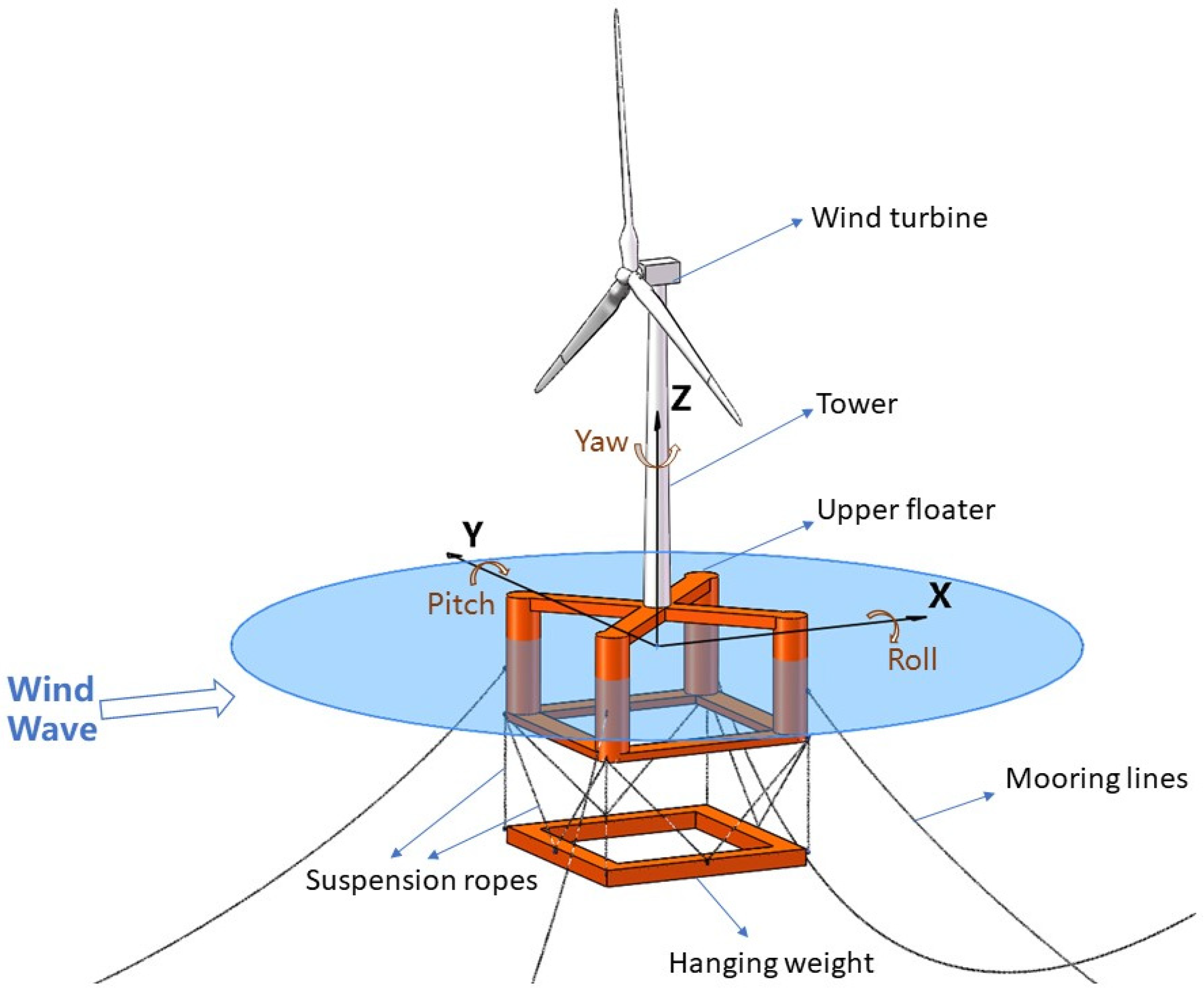
The proposed semi-spar floating wind turbine system is designed to be installed at a site with a medium water depth. In the present study, a water depth of 150 m is considered. According to the design, the floating wind turbine is composed of a 5 MW wind turbine, a tower, a two-body floating platform, and a mooring system. Figure 1 shows the conceptual design and the associated coordinate system employed in the present study. The coordinate system contains the origin fixed on the intersection of the tower centerline and the still water surface. While the z-axis is specified in the vertical direction pointing upwards, the x-axis is perpendicular to the rotor plane and pointing in the downwind direction.

Figure 1.
Conceptual semi-spar floating wind turbine design and the coordinate system.
2.1. Wind Turbine and Tower
In order to make the hydrodynamic assessment of the new semi-spar floating wind turbine comparable to the well-studied results corresponding to the design of OC3-spar and OC4-semisubmersible, the National Renewable Energy Laboratory (NREL) 5 MW baseline wind turbine is employed for installation on the new semi-spar floating platform. The baseline wind turbine is a three-bladed, upwind, horizontal-axis, variable-speed wind turbine. The detailed configurations of this baseline wind turbine can be found in the specifications [28] and repeated here in Table 1. It is noted that such a baseline turbine is also used in the studies concerning the evaluation of widely acknowledged floating platforms, such as the OC3-spar and OC4-semisubmersible platforms. In the present study, the hub height of the turbine is set as 90 m when measuring from the mean sea level since the deck height is 10 m for this innovative semi-spar platform, which is the same configuration for OC3-spar and OC4-semisubmersible wind turbine.

Table 1.
Properties of NREL 5 MW wind turbine.
2.2. Two-Body Floating Platform
The semi-spar floating platform proposed in the present study comprises an upper floater, a hanging weight, and several suspension ropes. The upper floater is a semisubmersible buoy that provides sufficient buoyancy. The hanging weight that lowers the center of gravity, on the other hand, is suspended below the upper floater through 12 suspension ropes. Figure 2 illustrates the structural configuration of the proposed floating foundation.
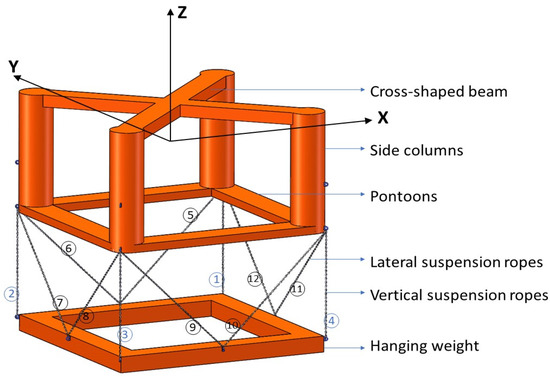
Figure 2.
Semi-spar platform.
The upper floater is a box-shaped body that consists of four side columns, four pontoons, and a top beam. In detail, the bases of the side columns are connected by four rectangular pontoons, and a cross-shaped beam links the tops of the side columns. The watertight compartments of the pontoons accommodate ballast water. The tower is mounted on the center of the cross-shaped beam. The draft of the upper floater is designed to be 20 m. Located beneath the upper floater, the hanging weight is a square-shaped ring, with concrete and seawater ballast filled inside. The ring is positioned at 50 m beneath the sea level to lower the center of gravity for the entire floating wind turbine. The geometric design of the platform is illustrated in Figure 3, and the main parameters are listed in Table 2. The large cross-section of the pontoon and counterweight highly increases the added mass of the substructure for translations in the vertical direction. In fact, such a configuration plays a similar role as the heave plate, raising the heave natural period away from the period range of energy-contained waves.
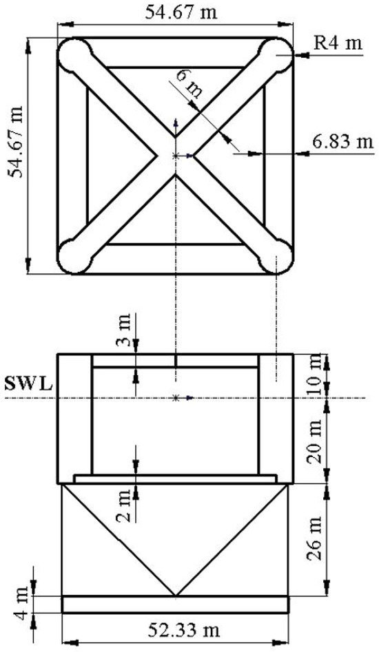
Figure 3.
Configuration of the semi-spar platform.
Table 2.
Main properties of the semi-spar platform (wind turbine, tower, mooring, and suspension system are excluded).
The floater and the hanging weight are arranged coaxially, connected by 12 suspension ropes, and the label of each rope is given in Figure 2. Among the suspension ropes, four are placed in the vertical direction at the corners of the substructure. The remaining right lateral ropes are placed evenly on all sides of the substructure. In other words, two ropes are arranged symmetrically on one side of the hanging ring. The vertical ropes at the corners undertake the bulk of the gravity load coming from the counterweight, while the lateral ropes are designed to reduce the relative motion between the floater and the hanging weight. Considering that the suspension ropes have to stand long-term fluctuating internal forces during service, and, hence, should keep in tension during service, both the material and the cross-section characteristics should be carefully designed. It is suggested that the rope could be made of steel chains, high-strength steel cables, or synthetic fiber, and both the strength and durability of the rope should be taken into consideration in the design. In the present study, 12 suspension ropes are assumed to be steel chains with a stiffness of 493.3 × 10³ kN, as shown in Table 3.
Table 3.
Properties of the mooring system and suspension system.
2.3. Mooring System
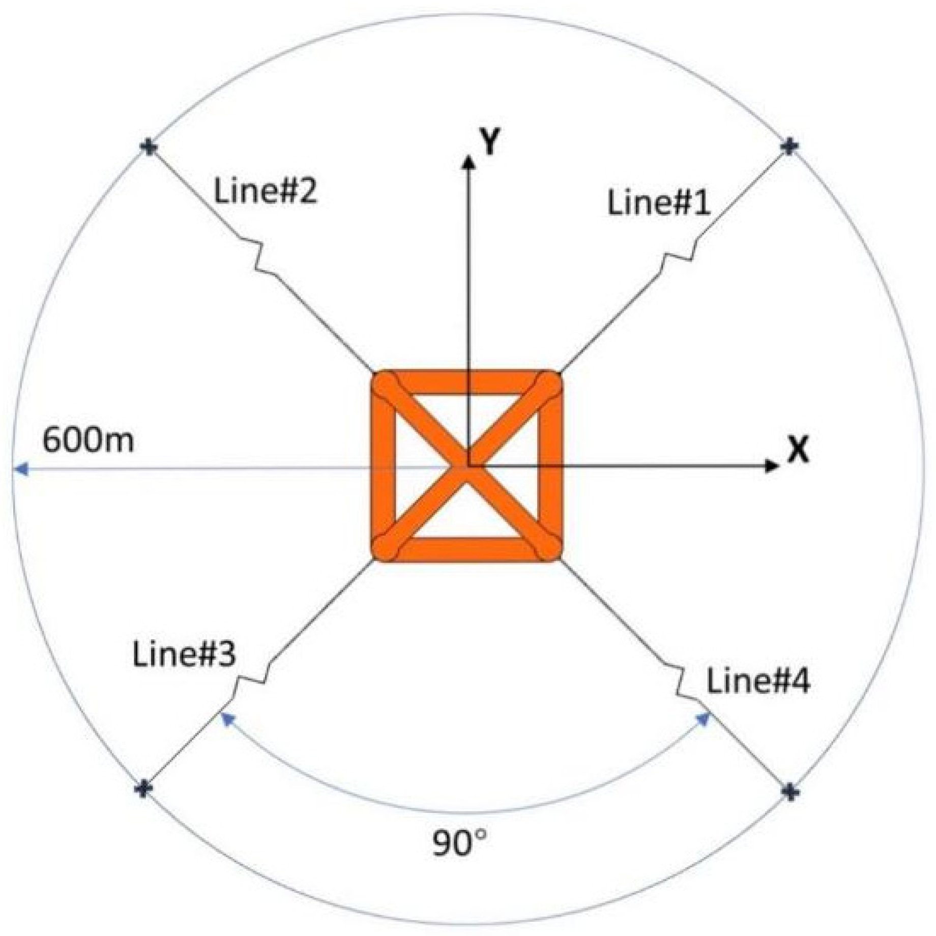
Four identical centenary mooring lines are used to moor the floating platform. The fairleads are fixed at the side columns of the upper floater, 8 m beneath the water. The anchors are assumed to be located at 150 m deep (seabed) and keep 600 m distance from the central axis. Figure 4 shows the layout of the mooring system, in which the four mooring lines are spread out symmetrically from the center of the floating wind turbine, and the angle between two adjacent mooring lines is designed to be 90°. A more detailed description of the relevant parameters of the mooring system is given in Table 3.
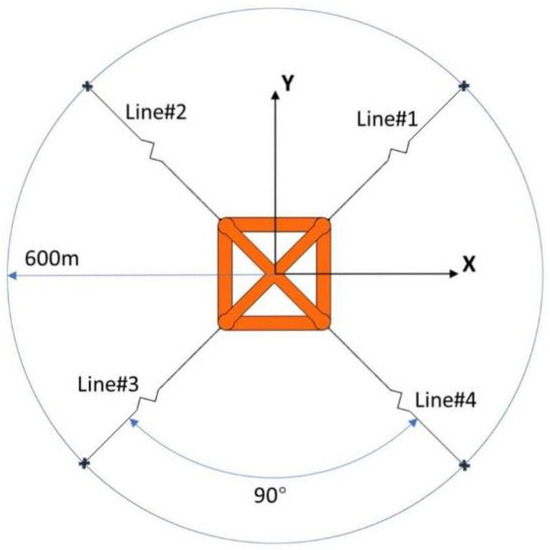
Figure 4.
Layout of mooring system.
2.4. Features and Performance
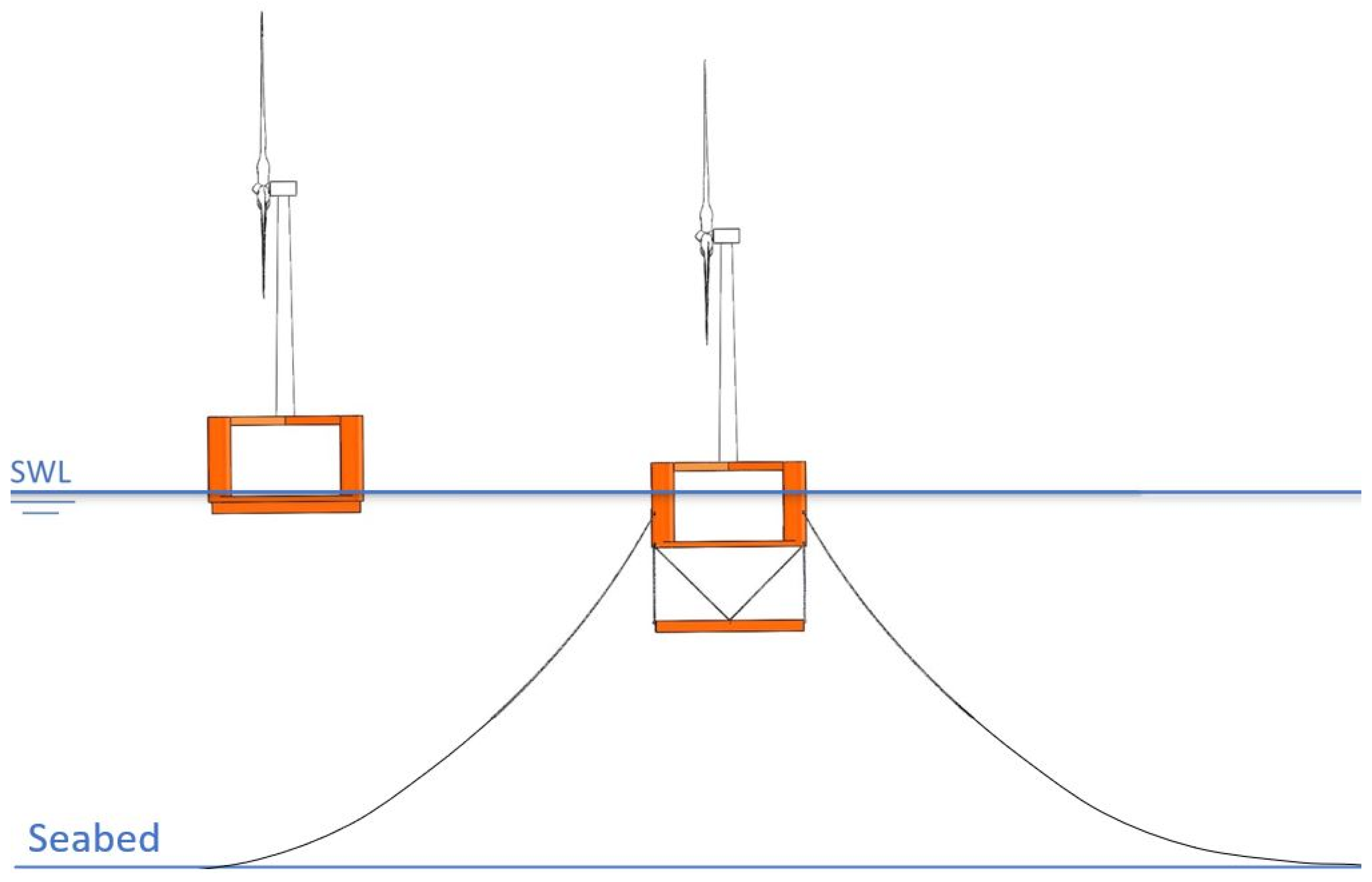
The innovative semi-spar floating wind turbine is designed for easy offshore transportation and installation. During the wet towage process, the hanging weight is partially ballasted; therefore, it is closely attached to the bottom of the floater under the action of buoyancy. Meanwhile, suspension ropes are hung slackly by the side of the substructure, with both ends fixed to the upper floater and hanging weight. Thus, it can be wet towed to the installation site as a conventional semisubmersible foundation, as shown in Figure 5. The floating system has a shallow draught of 7 m during towage, which significantly reduces hydraulic resistance.

Figure 5.
Wet towing and operational phase of semi-spar floating wind turbine (Left: wet towing, right: operation).
Once arriving at the designated location, the hanging weight will be filled with seawater and sink slowly until it reaches the predetermined depth. In this phase, the suspension ropes are gradually tensioned and pull the floater down to the designed draft. Finally, the floating system presents a spar-type structure with inherent stability.
3. Numerical Model
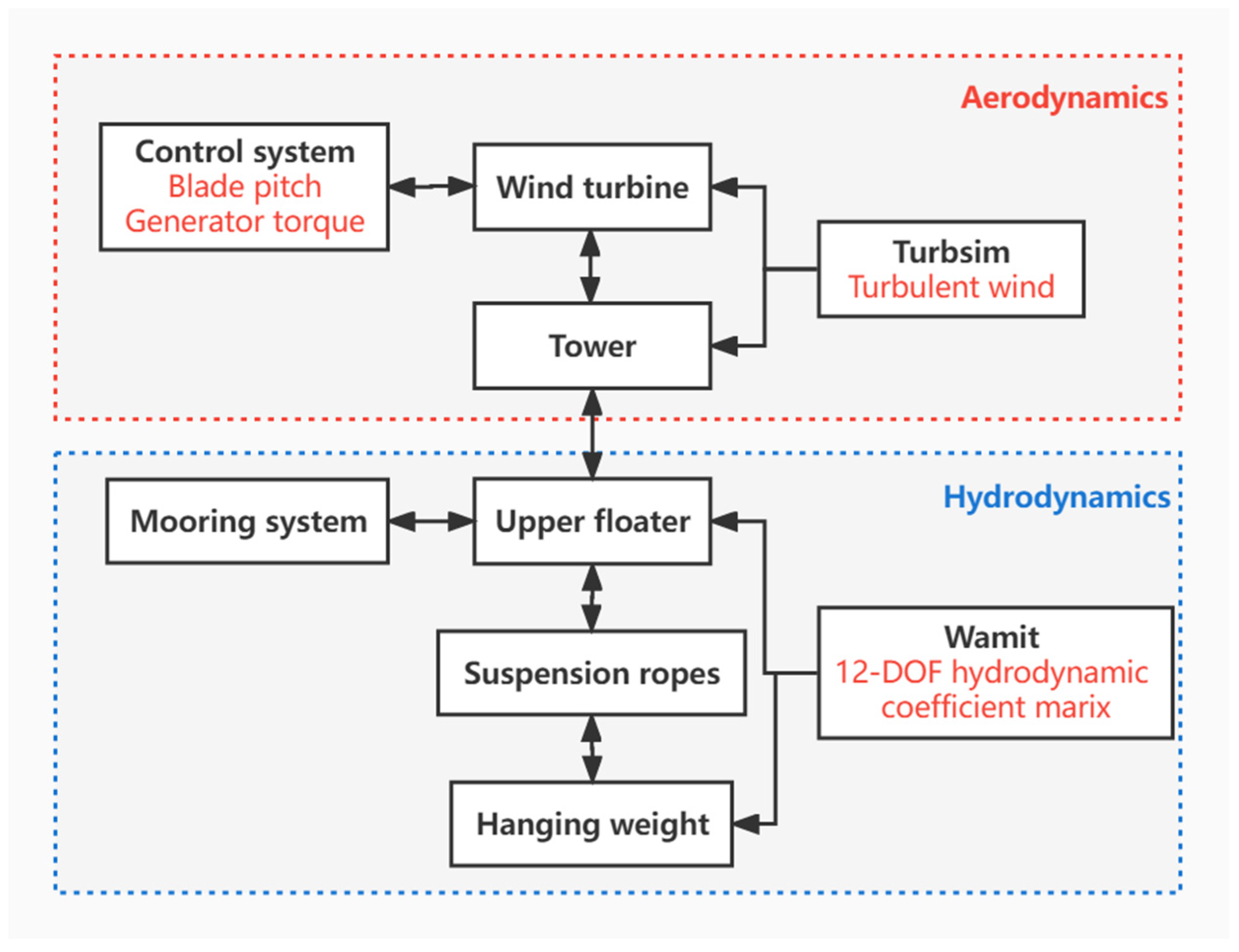
The floating wind turbine is a complicated multi-degree-of-freedom (DOF) system subjected to severe environmental loads, and the motion response of different components interact with each other. How to accurately predict the dynamic performance of each component is of great importance to the investigation of floating wind turbines. In this study, a numerical tool, namely, OrcaFlex version 11.1 [29] is used to perform a fully coupled aero-hydro-servo-elastic analysis for the proposed semi-spar floating wind turbine in the time domain. OrcaFlex is a nonlinear numerical simulation package in the time domain developed by Orcina that is mainly used for static and dynamic response simulations of offshore structures. Moreover, OrcaFlex is capable of simulating the rotating wind turbine under operation conditions and the dynamics of multi-floating bodies. In the OrcaFlex simulation, the aerodynamics of wind turbines and towers, the hydrodynamics of floating platforms and mooring lines, the control over the blade pitch angle and rotor torque, and the elastic deformation of towers, blades, mooring lines, and suspension ropes are all taken into account, and the response to each part is solved subsequently in the simulation time steps. Figure 6 shows the flow chart of the numerical simulation.
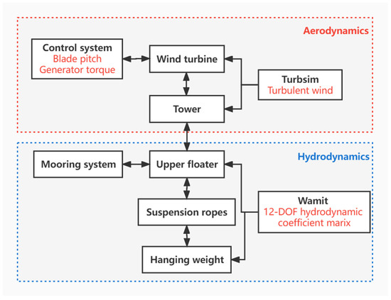
Figure 6.
A sketch of the numerical simulation flow.
3.1. Governing Equation of Motion
In most cases, the foundation of a floating platform is a 6-DOF rigid body, and the governing motion equation is established according to the Cummins equation [30] as follows:
In Equation (1), is the mass matrix of the foundation, is the added mass matrix at infinite frequency, is the hydrostatic restoring matrix, and is the summation of external forces acting on the floater. , d are the displacement, velocity, and acceleration vector in the time domain, respectively. is the retardation function matrix, which reflects the wave memory effects and can be solved based on the frequency-dependent added mass matrix or linear radiation damping matrix :
The semi-spar’s foundation is composed of two rigid bodies with 12 DOFs, and the external forces acting on the two bodies differ significantly. Both the wind turbine and mooring system are fixed on the upper floater; therefore, the upper body is exposed to a more severe environment, including not only the incident wave excitation force and nonlinear viscous drag force but also the aerodynamic load acting on the wind turbine and transferred to the floating platform, the mooring line restoring force, and the tension of the suspension rope. The hanging weight section is fully submerged in water; hence, it is only subjected to the incident wave excitation force and viscous drag force from the fluid, as well as the tension of the lanyard connected to the upper floater.
Therefore, by extending Equation (1) and taking into account the hydrodynamic coupling effects, the nonlinear time-domain equation of motion for the two-body floating foundation can be expressed as [31]:
where the subscripts 1 or 11 stand for variables in association with the upper floater, subscripts 2 or 22 stand for variables in association with the hanging weight, and subscripts 12 or 21 stand for the coupling terms.
3.2. Aerodynamic Loads
, shown in Equation (3), is the aerodynamic loads acting on the wind turbine and tower. The former is mainly manifested as the aerodynamic force on the blades, which is calculated based on element momentum theory, and corrections considering tip loss, hub loss, and skewed wake effects are made. The aerodynamic loads on the tower can be calculated as,
In Equation (4), is the air density, is the aerodynamic drag coefficient, is the tower projected area, and is the relative wind speed.
The vibration of the blades and the tower are solved through finite element analysis, and the control over the wind turbine generator torque and blade pitches are added through the external application programming interface.
3.3. Hydrodynamic Loads
The hydrodynamic forces are solved based on the combination of potential flow theory and Morison’s equation, and the hydrodynamic coefficients of the upper floater and the hanging weight are calculated in the frequency domain using the well-accepted tool WAMIT version 7.0 [32]. Specifically, the added mass and damping, the first-order wave force, and hydrostatic restoring matrices corresponding to the upper floater and the hanging weight are calculated using WAMIT, which shows the hydrodynamic performance of the semi-spar platform. In the numerical simulation, these hydrodynamic coefficients are then imported as the multi-body vessel element into the OrcaFlex simulation and converted to the time domain through convolution. As only the first-order wave force is considered in this study, the incident wave excitation force can be expressed as [11]:
In Equation (5), is the wave surface elevation; is the impulse response function obtained through Fourier transformation:
where is the first-order wave force transfer function calculated in the frequency domain.
It is noted that the hydrodynamic coefficients obtained using WAMIT are estimated based on the potential flow theory, which ignores the viscous effect in the interactions between the floating platform and the sea flow. Previous studies have found that the viscous drag force is not negligible for slender rods [33,34]. Therefore, the influence of viscous drag force is included in the OrcaFlex simulation by introducing Morison elements in the modeling of pontoons, columns, and hanging weight of the semi-spar platform. is the viscous drag force calculated through Morison’s equation, it complements the fluid viscous effect neglected in the potential flow theory:
In Equation (7), is the viscous drag coefficient, is the projection area, is the water density, and is the water particle velocity.
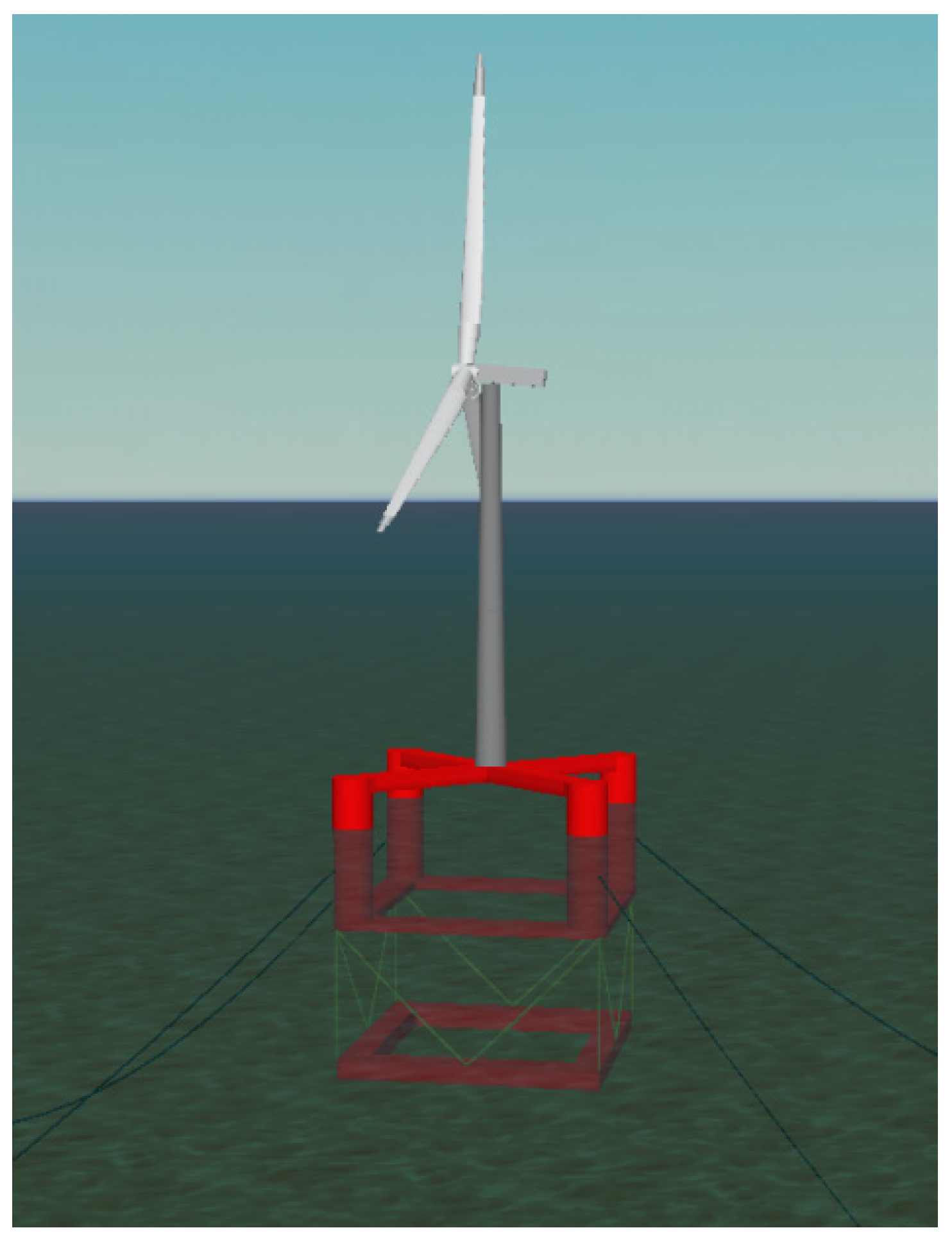
Figure 7 and Figure 8, respectively, show the model of the semi-spar floating wind turbine employed in the time domain simulation conducted using OrcaFlex and the panels of its wetted surface set up in the calculation of the hydrodynamic coefficients of the WAMIT simulation.
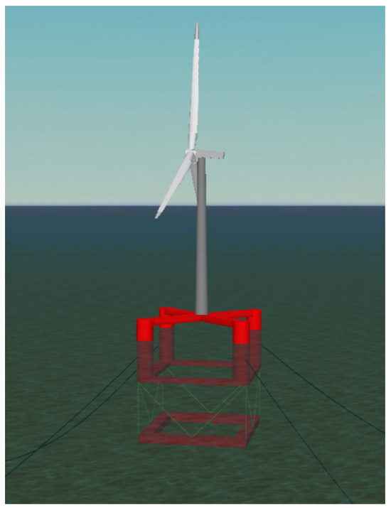
Figure 7.
A numerical model of the semi-spar foundation in the OrcaFlex simulation.

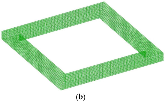
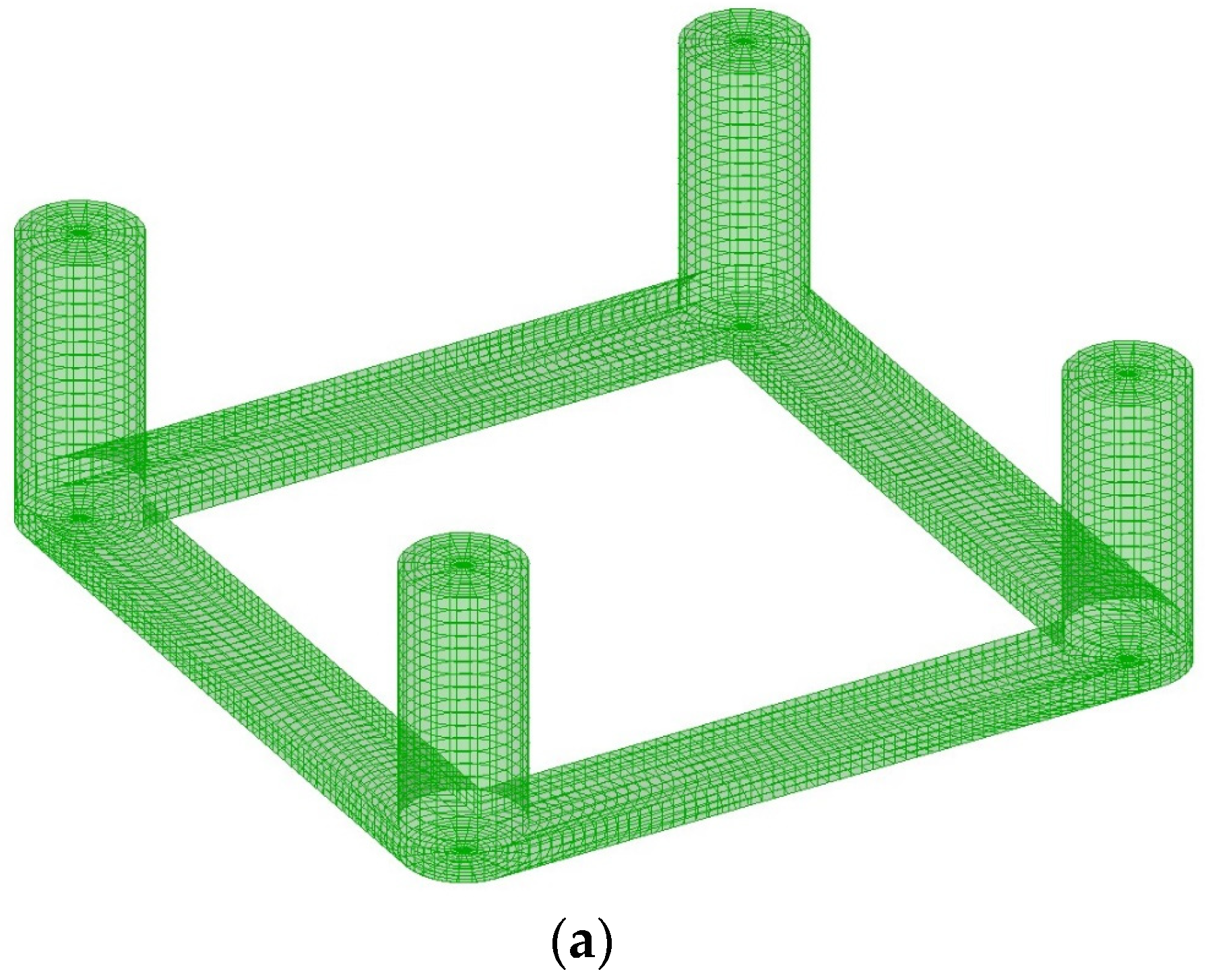
Figure 8.
Panel model of semi-spar foundation: (a) upper floater; (b) hanging weight.
3.4. Tension of Mooring Lines and Suspension Ropes
is the restoring force from mooring lines and is the tensile force of 12 suspension ropes; both are simulated as line elements in OrcaFlex. The line element is divided into a series of segments that are represented by a massless spring and a node at the end, and the mass of the segment is lumped at the node. The tensile force of a segment is calculated as:
In Equation (8), is the axial stiffness of the line, is the axial strain, is the length of the segment, is the unstretched length of the segment, and is the damping coefficient.
The hydrodynamic drag forces of the mooring lines and suspension ropes are also considered via the Morison model in Equation (7). It is assumed that tension and other external forces are applied to the node of the line element. The tension of mooring lines is mainly determined by the motion of the upper floater. Whereas, the tensile forces of the suspension ropes are mainly determined by the relative positions of the upper and lower body through solving Equation (3).
3.5. Environmental Conditions
The hydrodynamic performance of the proposed semi-spar floating wind turbine is assessed at a potential offshore wind farm site with a water depth of 150 m. The dynamic responses of the floating wind turbine are evaluated under (a) normal working conditions, (b) one-year, return-period wind–wave loads, and (c) fifty-year, return-period wind–wave loads. In the assessment, it is assumed that both the wind and wave attack the floating wind turbine from an angle of 0°. While the Pierson–Moskowitz (PM) spectrum model [35] is used to describe the attacking waves, the Kaimal spectrum model [36] is used for generating a pseudo stochastic wind field using TurbSim version 1.06 [37] shipped with the OpenFAST package. The pseudo stochastic wave field, on the other hand, is generated using OrcaFlex. Table 4 summarizes the key parameters defining the environmental loads acting on the floating wind turbine under different conditions.
Table 4.
Environmental conditions [38].
4. Results and Discussions
Based on the OrcaFlex simulation results concerning both the elastic responses of various components of the wind turbine and the motion of the floating platform, the dynamic characteristics of the proposed semi-spar platform are discerned. In detail, the dynamic characteristics in the discussion include the connections between the upper floater and hanging weight, the natural frequency, the Response Amplitude Operators (RAOs) of the entire floating platform, the hydrostatic assessment of the floating platform in the towing process, the dynamic responses of the proposed semi-spar floating wind turbine under the wind–wave excitation and the ultimate states of the mooring lines and suspension ropes, the tension of 12 suspension ropes with different wave directions, and the cost-effectiveness.
4.1. Motion Comparison of Upper Floater and Hanging Weight
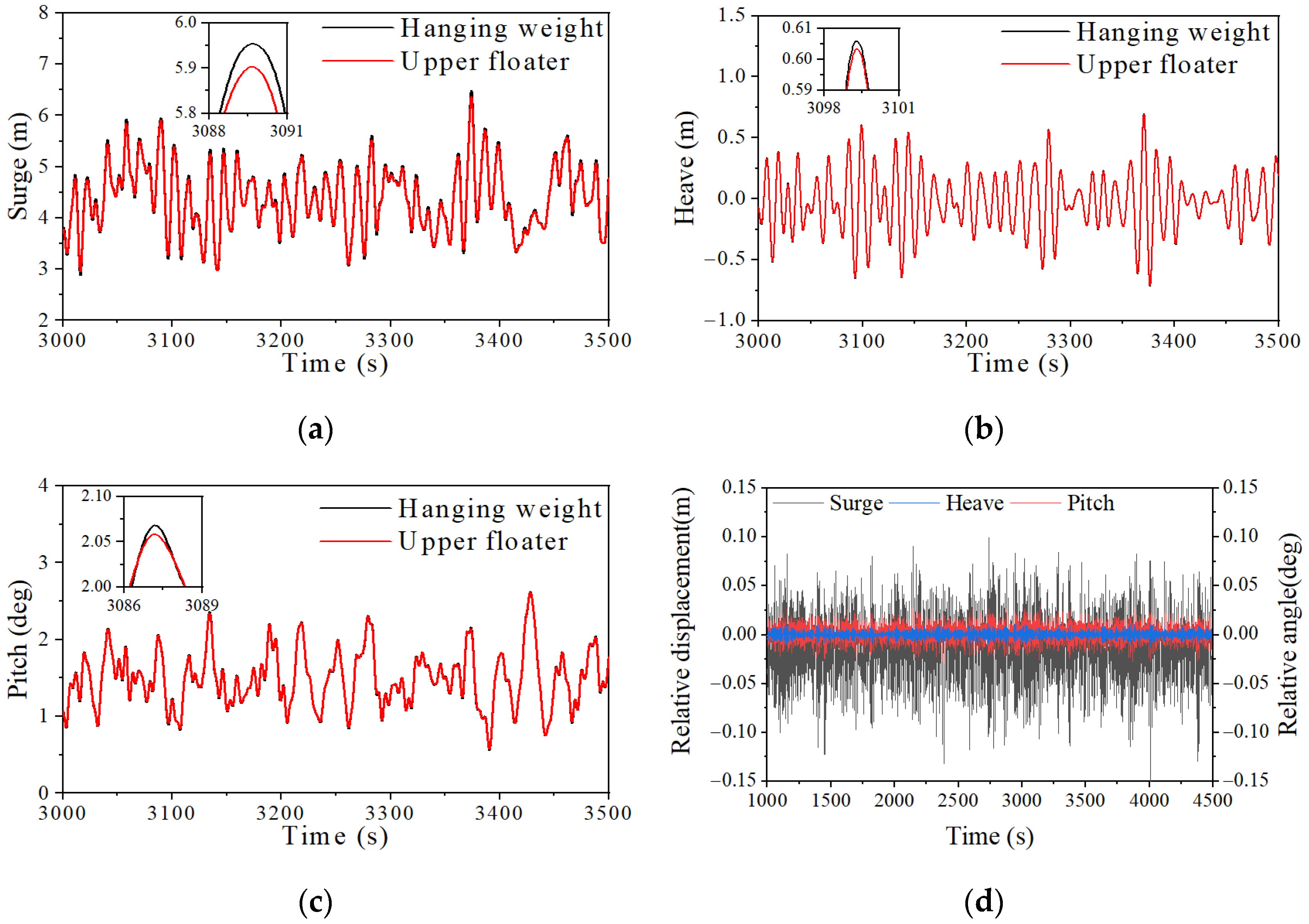
In the numerical simulation, the upper floater and hanging weight are modeled as two independent rigid bodies, and, hence, their motions are not completely synchronized. Figure 9 compares the movement of the upper floater and hanging weight under the load case of EC2 (Figure 9a–c) and shows the relative motion difference between them (Figure 9d). Only minor differences are observed in the motions of the upper floater and the hanging weight. In fact, the differences in their motions are less than 0.2 m for the surge, 0.025 m for the heave, and 0.05 deg for the pitch. This indicates that the two bodies are closely connected and that their motion difference can be neglected. Consequently, the focus of this study is on the movement of the upper floating body, where the wind turbine is installed. Unless otherwise specified, the motion of the upper floater is referred to as the motion of the entire floating platform in the following discussion.
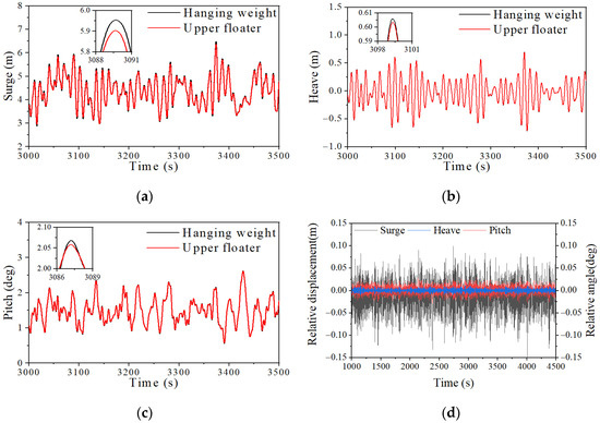
Figure 9.
Motion comparison between upper floater and hanging weight under EC2: (a) surge; (b) heave; (c) pitch, and (d) motion difference.
4.2. Natural Frequency and RAOs
The natural frequencies of the floating platform are estimated in still water without wind given an initial displacement in a specific direction. Based on the time histories of the floating platform motions produced using the numerical simulation, the natural frequencies are identified and shown in Table 5. To facilitate the following comparison with the well-accepted OC3-spar and OC4-semisubmersible floating wind turbines, their natural frequencies are also listed in the table. It can be seen that the natural frequencies of the proposed semi-spar floater are far away from the range of the energy-contained frequency range of waves as well as the 1P and 3P frequencies of the wind turbine, which are given in Table 6. In summary, the natural frequencies of the proposed design successfully avoid resonance induced by a first-order wave force and also the 1P and 3P effects of wind turbine rotating.
Table 5.
Natural frequencies.
Table 6.
1P and 3P frequency of NREL 5MW RWT.
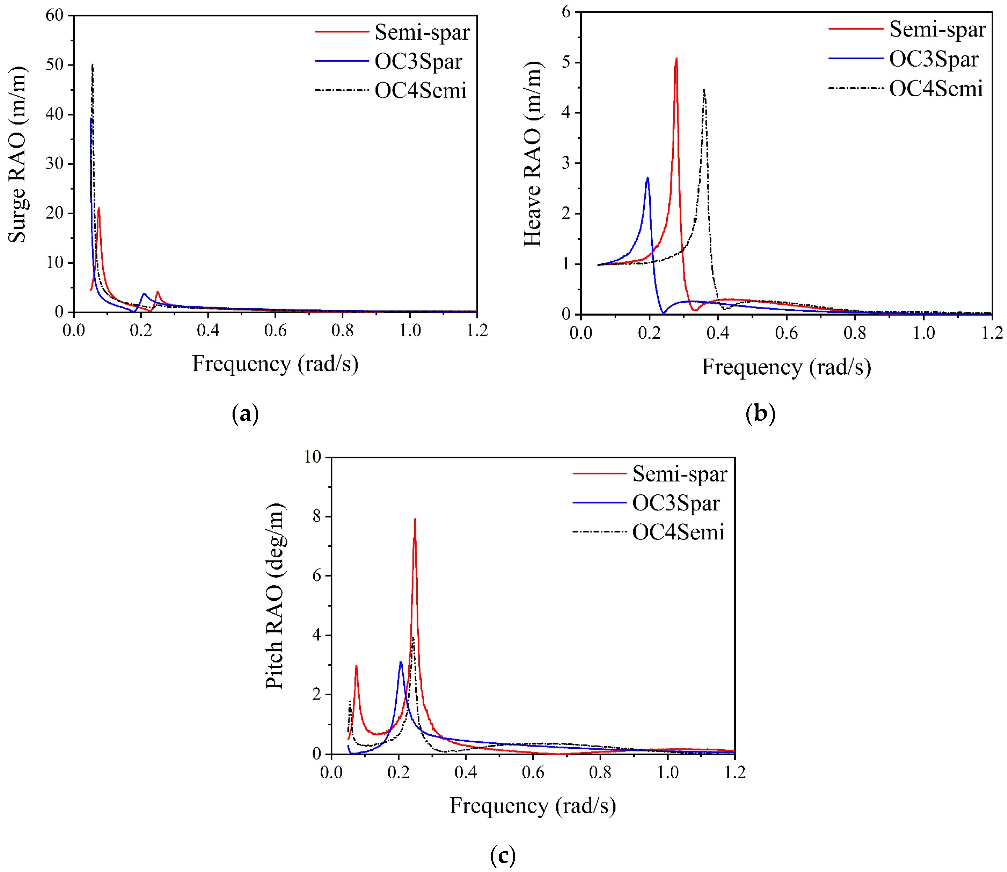
RAOs are important parameters, in addition to the natural frequency, that reflect the inherent behavior of the structure under the waves. In the present study, the white noise wave is used to excite the motion of the proposed semi-spar floating platform, which, in turn, derives the RAOs of the platform. The white noise waves, corresponding to the wave height of 2 m and frequencies in the range of 0.008–0.508 Hz, excite the motion of the floating wind turbine repeatedly with three different initial phases. The simulation duration of a single white noise test is 6500 s, with no wind and current, and the wind turbine is parked. The results of the three tests are averaged to minimize the random effect. Based on the white noise test results, RAOs are calculated as [39],
In Equation (9), and are the cross-spectral and auto-spectral densities of the wave elevation and the platform response , respectively. The RAOs calculated from the white noise tests are plotted in Figure 10 with the comparisons of RAOs corresponding to the OC3-spar and OC4-semisubmersible floating platforms.
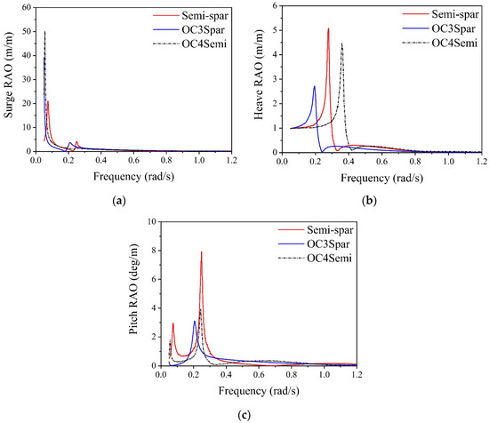
Figure 10.
Comparison of RAOs between semi-spar, OC3-spar, and OC4-semisubmersible: (a) surge; (b) heave; (c) pitch.
It can be seen in Figure 10 that the natural frequency of the proposed design in the heave direction lies between OC4-semisubmersible and OC3-spar, and the peak value corresponding to the proposed semi-spar design is higher than that of the other two platforms. The heave RAO of the proposed design is roughly the same as the OC4-semisubmersible platform at frequencies exceeding 0.48 rad/s, which is higher than the RAO of the OC3-spar platform, since the OC3-spar platform possesses a much deeper draft and much smaller waterplane area. The peak of the pitch RAO of the proposed semi-spar design is larger than the other two designs in the comparison; however, its RAO is the smallest in the energy-contained wave frequency range of 0.42–0.9 rad/s.
4.3. Hydrostatic Stability during Transportation Phase
The offshore floating wind turbine is subjected to a huge wind tilting moment due to its upper towering structure, which makes it prone to capsizing. The proposed design has a center of gravity lower than the buoyancy center; thus, it is inherently stable when finishing the installation. In the case of marine towage, the floating foundation is, essentially, a semisubmersible floater and needs to be calibrated for stability due to the shallow draft during the transportation phase.
Collu et al. [40] proposed non-operational stability requirements for semisubmersible floating wind turbines after synthesizing the existing stability guidelines and guidance on offshore floating platforms, which are applicable in the present study.
- the area under the righting moment curve to the second intercept or the angle of down flooding, whichever is smaller, should not be less than 130% of the area under the heeling moment curve to the same limiting angle [41];
- the righting moment curve should be positive over the entire range of angles from upright to the second intercept [41];
- the maximum tilt angle under the heeling moment should not exceed 15°;
- the metacentric height has to be 1 m at least;
- the static range of stability should not be less than 15° at the draught of wet-towing.
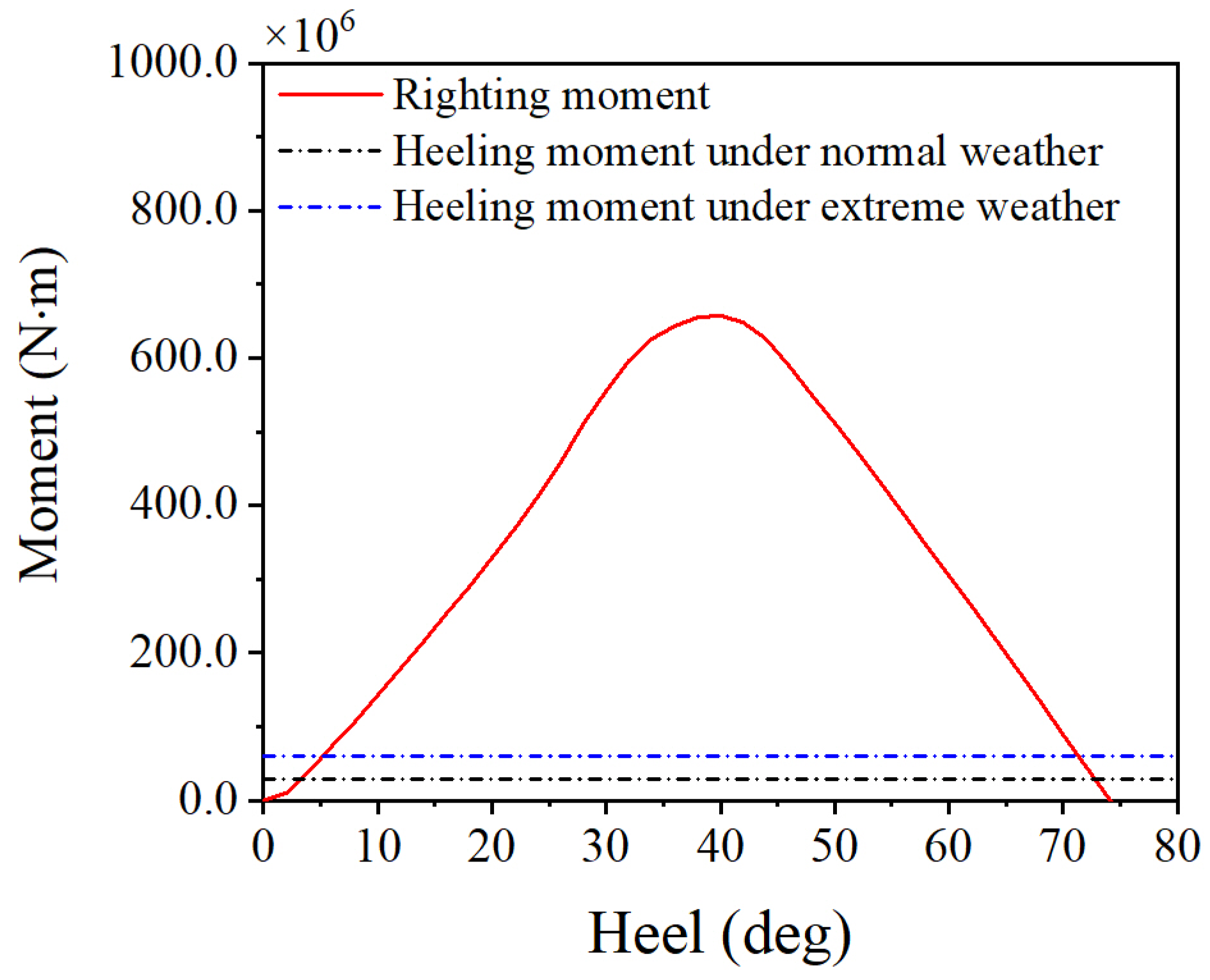
Usually, offshore wet towage is carried out under good weather; however, considering that the process may last for several weeks, extreme weather conditions should also be taken into account. The wind speed for tow stability assessment is chosen as 36 m/s under normal weather and 51.5 m/s under extreme weather, with the wind turbine blades feathered [40,42,43]. The heeling moments under different weather conditions are calculated and shown in Table 7, with the wind load acting on the floating platform neglected. It should be noted that the wind heeling moment is assumed to be a fixed value in the process of hull tilt. The assumption is conservative, as the real wind heeling moment decreases with the increase in the hull tilting angle. Figure 11 shows the heeling moment curve and the righting moment curve of the semi-spar during wet towing. It can be seen that the semi-spar has a large static stability range of 74°, and the first intersection of the heeling moment curve and the righting moment curve for two weather conditions is 3.5° and 5° respectively. The ratio between the area below the righting moment curve and the area below the wind heeling moment curve is obviously much larger than 1.3, with the righting moment staying positive in this range. In addition, the metacentric height at a heel angle of 0° is about 4.36 m.
Table 7.
Main parameters of wet towing stability analysis.

Figure 11.
Stability curve of semi-spar floating wind turbine during wet towing.
4.4. Responses under Combined Wind and Wave
To further investigate the responses of the proposed semi-spar design exposed to the predefined environment, the wind and wave parameters are set in the numerical simulation according to the environmental conditions listed in Table 4. Three different random seeds are used to generate the wind and wave time series in the simulation, and a single simulation duration is specified as 4600 s for a certain load case with a specific random seed. The first 1000 s of data are excluded from the frequency-domain analysis to discard transient effects.
4.4.1. Platform Motion
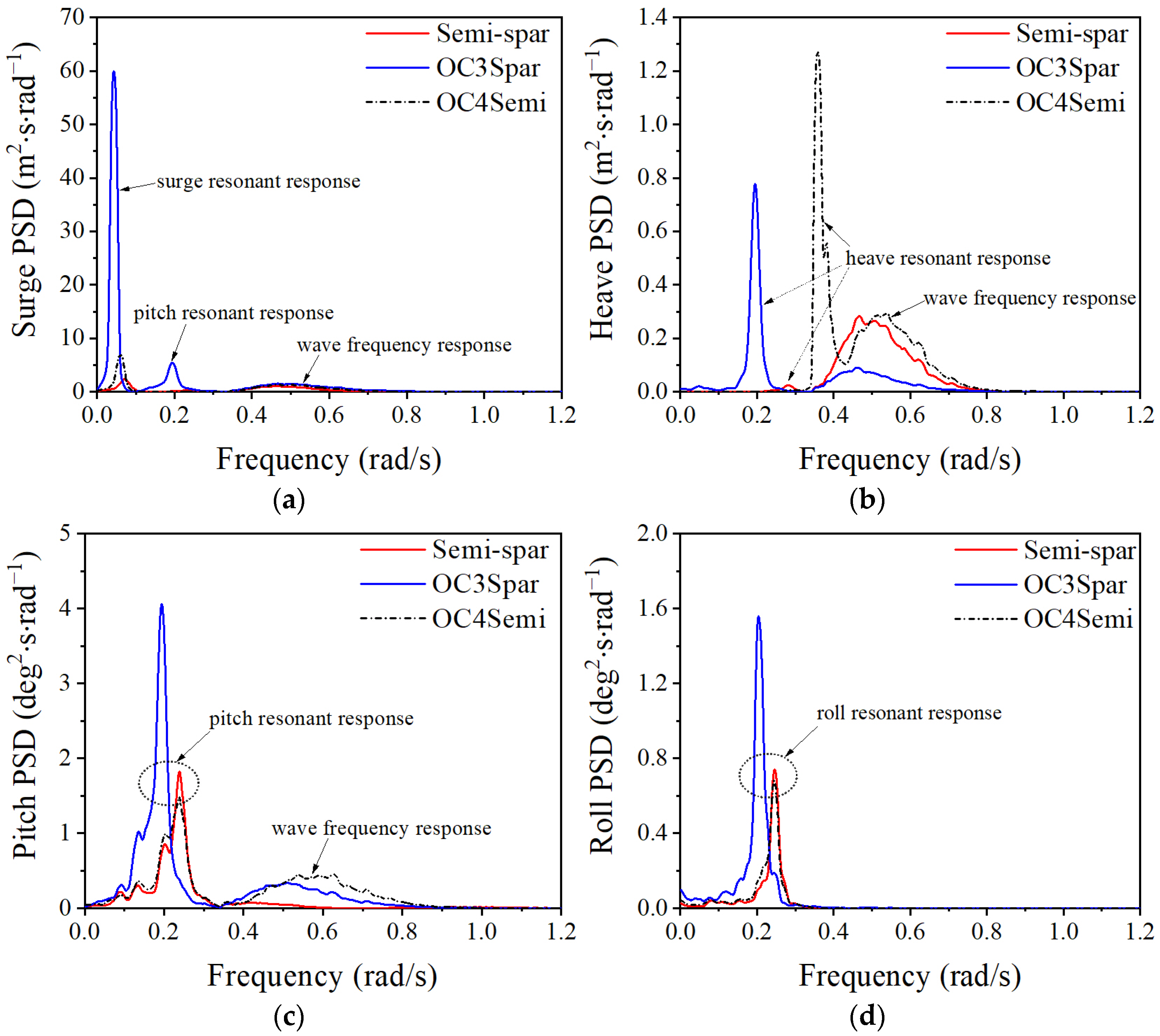
Figure 12 presents the power spectral density of motion responses for the three floating platforms under the load case of EC2. Regarding the surge spectrum, the three designs all have their first peak at the surge natural frequency and a wider peak at the energy-containing wave frequency. The power spectral density of the proposed semi-spar at these two intervals is smaller than that of the other two designs, indicating that the semi-spar design is less responsive to low-frequency wind excitation and wave excitation. Considering the heave motion, Figure 12 reveals that the heave motion of the semi-spar design is dominated by the wave excitation force, and it exhibits a much less significant response in its natural frequency compared to the other two designs. The power spectral density of the OC3-spar design is, on the other hand, less than half of the semi-spar design and the OC4-semisubmersible in the wave frequency range, which is mainly attributed to its relatively deeper draught and lower gravitational center. Regarding the pitch motion, a sharp peak corresponding to the natural frequency of the platform is observed for all three designs, indicating that the pitch resonant response is significant. In addition, the spectral density of the semi-spar design within the wave frequency range is much smaller than the other two designs, confirming its superior hydrodynamic characteristic in the pitch direction. A peak similar to the pitch spectrum is observed in the low-frequency region of the roll PSD spectra for all three floating wind turbines, while the response in the wave frequency region was small, mainly due to the fact that the wind and wave loads are all along the 0-degree direction.
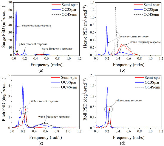
Figure 12.
Power spectral density of platform motion under EC2: (a) surge; (b) heave; (c) pitch; (d) roll.
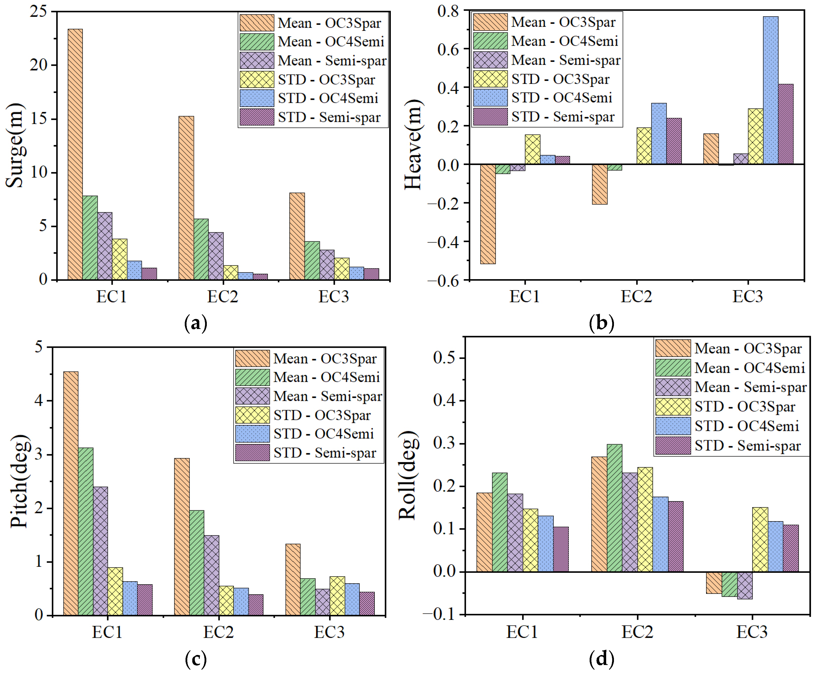
Subsequently, a statistical comparison of the hydrodynamic performance is given in Figure 13. It can be observed that the proposed semi-spar has a minimum mean and standard deviation of surge and pitch motion responses under all the load cases. More specifically, Figure 13 shows more than 50% and 30% reductions in surge and pitch responses, respectively, of the proposed semi-spar platform compared to the OC3-spar platform. The stability of the proposed semi-spar type in the surge direction is mainly attributed to the well-designed mooring system, while the small mean pitch angle is in association with the large waterplane moment of inertia. In fact, the mean pitch angle of the proposed semi-spar design does not exceed 3° under all load conditions. Moreover, it can also be found that the mean value of the surge and pitch becomes smaller from the load case of EC1 to EC3, while the standard deviation does not share the same trend. Moreover, the standard deviation of the semi-spar design in heave motions lies between the boundaries corresponding to the OC3-spar and OC4-semisubmersible platform. As for the roll motion, despite the small dynamic response, it can still be seen that the standard deviation of the semi-spar’s motion response is the smallest among the three floating wind turbines.
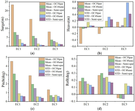
Figure 13.
Statistical results of platform motion: (a) surge; (b) heave; (c) pitch; (d) roll.
4.4.2. Tower Base Fore-Aft Bending Moment
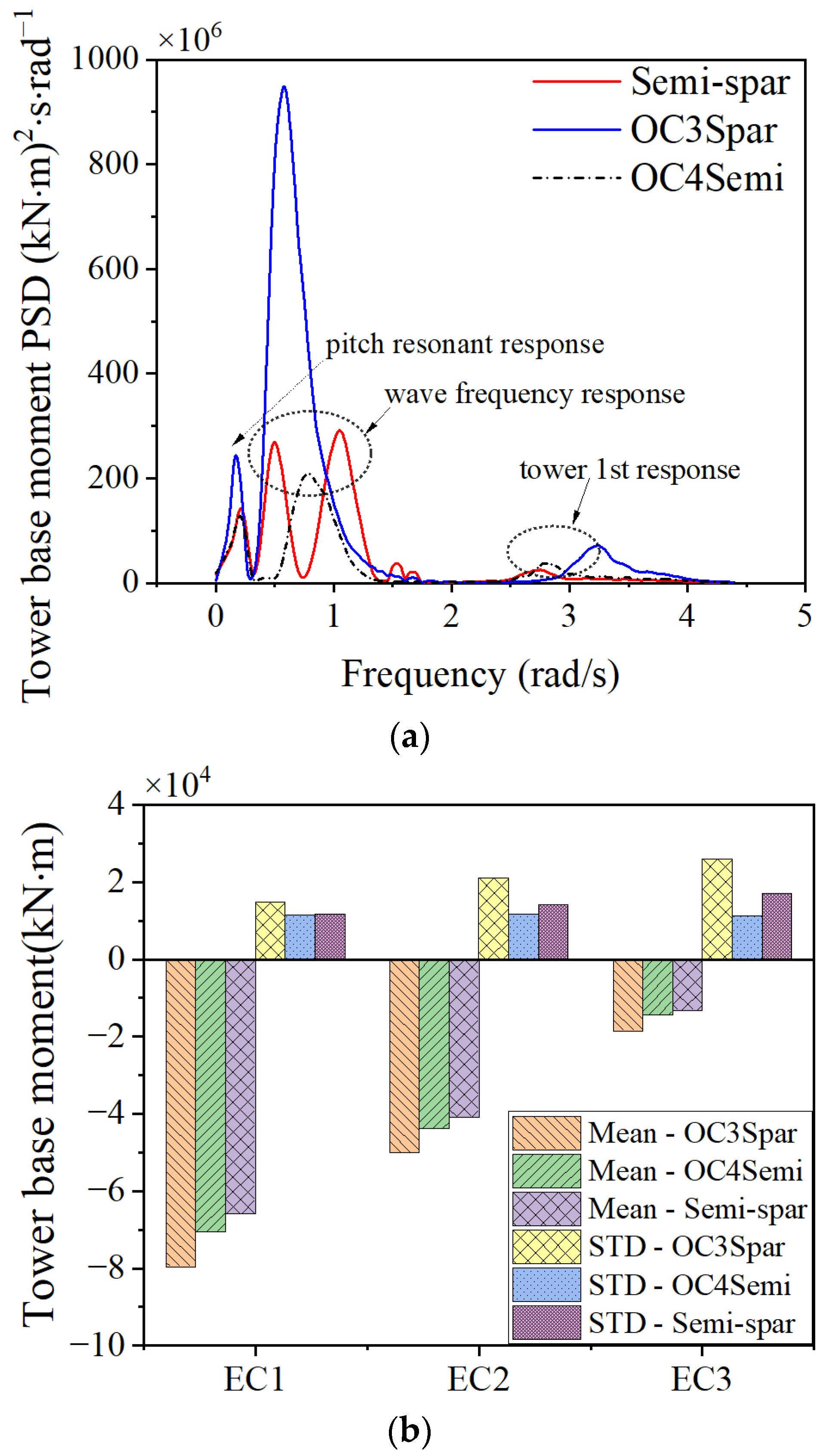
The tower is a crucial component connecting the top wind turbine to the bottom foundation. Owing to its height, the top-heavy assembly exerts a large bending moment on the tower base. The power spectral density of the tower base fore–aft bending moment under the load case of EC2 is plotted in Figure 14a, and the statistic results are presented in Figure 14b in order to assess the structural performance of the proposed semi-spar platform.
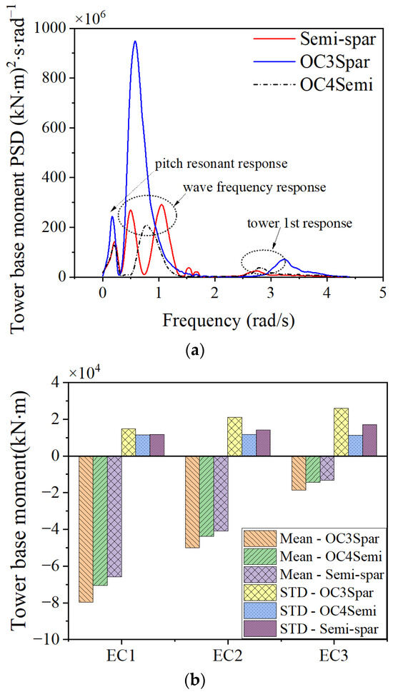
Figure 14.
(a) Power spectral density under EC2; (b) statistical values of tower base fore–aft bending moment.
Regarding the power spectral density, several peaks are observed within the frequency range of 0–5 rad/s for all three designs under investigation. For the semi-spar design, the peak at 0.22 rad/s corresponds to the pitch resonant response, and the peak amplitude is close to the OC4-semisubmersible platform; however, only half of the peak is associated with the OC3-spar platform. In the energy-containing frequency range of waves, two obvious peaks are observed for the proposed semi-spar design, while only one peak is observed for the other two designs. The difference is mainly caused by the shape of the submerged structure. As discussed by Cao et al. [11], the length of the column, pontoon, and rod that comprise the floater, as well as the way they are organized, have a significant impact on the wave diffraction forces. An additional peak appearing at the higher frequency of 2.75 rad/s is believed to be associated with the first tower fore–aft natural frequency, and the semi-spar design shows the smallest response in this frequency band among the three designs.
Concerning the statistical results, a similar trend, as indicated in Figure 13, is found in Figure 14, where the mean value of the tower base bending moment under the extreme load case of EC3 is smaller than that under the normal operating sea state of EC1. In addition, the average tower base bending moment of the semi-spar platform is smaller than that of the other two designs under all three different conditions. However, the standard deviation of the bending moment corresponding to the proposed semi-spar platform is slightly larger than that of the OC4-semisubmersible design.
4.5. Ultimate Strength of Mooring Lines and Suspension Ropes
Moorings and suspension ropes are components that are crucial to the safety of the proposed design of the floating platform; however, they are prone to fracture damage due to their flexibility and reciprocating load. In this section, their strength under extreme sea conditions is assessed.
DNV [44] offers guidelines for validating the design of the mooring lines in the ultimate state, and the method is taken for the mooring lines #2 and #3 as they are located upwind and, hence, endure greater tension than the other two moorings in the present study. In addition, these procedures are followed for the assessment of suspension ropes, considering that the mooring lines and suspension ropes share a similar chain structure. According to the guide, the mooring line strength shall meet the following requirements:
In Equation (10), is the utilization factor; is the characteristic strength, which is taken as the minimum breaking strength in the present study; is the pretension of the mooring line; is the characteristic environmental tension, ; is the maximum probability value of the mooring line tension during the 3 h simulation; and are the partial safety factors, chosen as 1.2 and 1.45 [44].
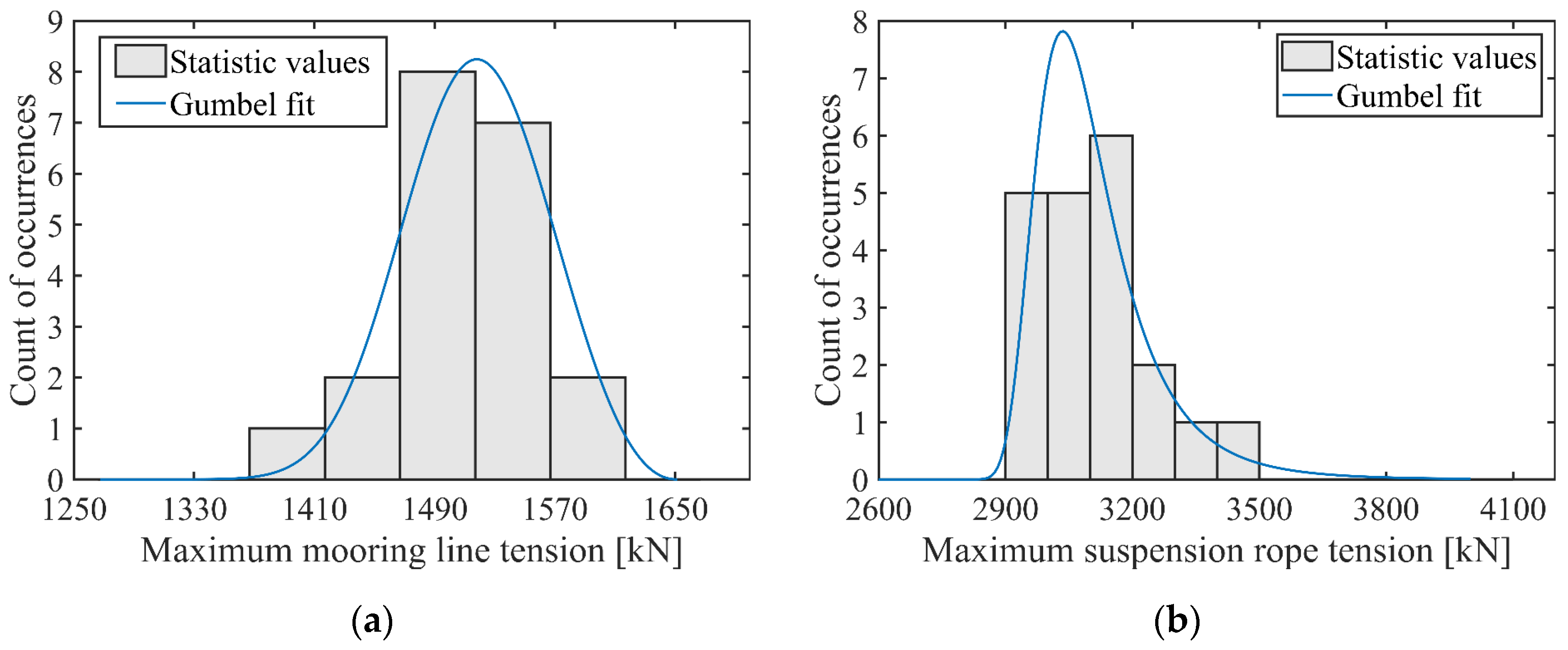
In solving for , 10–20 groups of simulations with a duration of 3 h are required, and the maximum value of each group is taken as a sample for subsequent analysis. Afterward, a probability analysis is performed on the series of extreme values obtained from all the groups. Assuming that the extreme value sequence conforms to the Gumbel extreme value distribution, the parameters are fitted to obtain . Figure 15 shows the results of the extreme value analysis corresponding to mooring line #2 and suspension rope #6. In addition, the calculation results of mooring line #2 and suspension ropes #1, #2, #5, #6, #7, and #8 are listed in Table 8, which shows that the suspension ropes and mooring lines all meet the requirements.
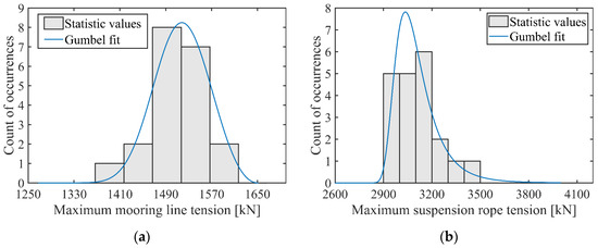
Figure 15.
Gumbel fit of the maximum mooring line and suspension rope tension: (a) mooring line #2; (b) suspension rope #6.
Table 8.
Ultimate strength calculation of mooring lines and suspension ropes.
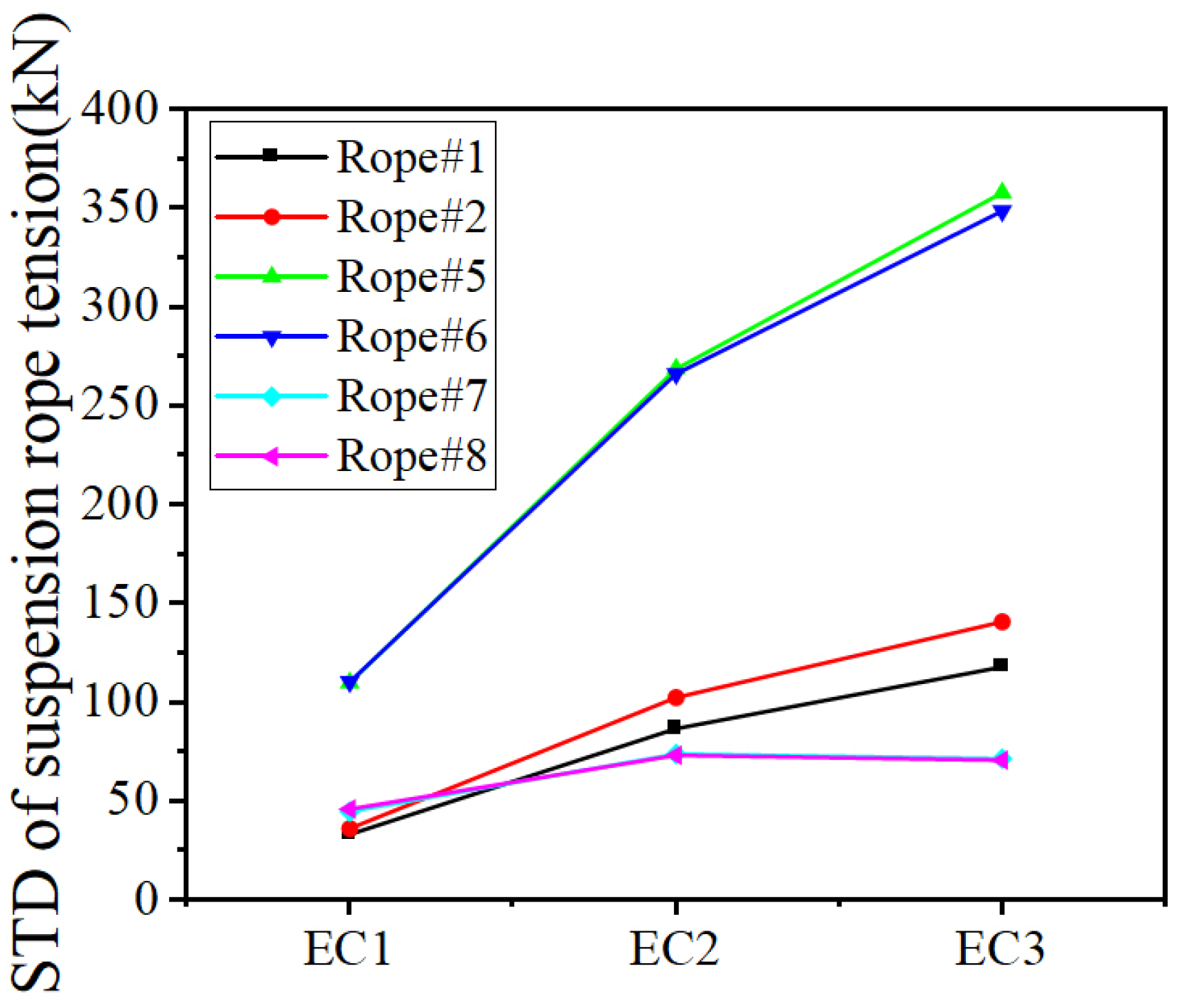
Comparing with , it can be found that the tension of the vertical suspension ropes (ropes #1, #2, #3, #4) maintains a high level with little fluctuation since they mainly endure the gravity of the hanging weight and are less affected by platform movement. The maximum tension of lateral suspension ropes #5, #6, #9, and #10 parallel to the wave direction is, on the other hand, far greater than that of suspension ropes #7, #8, #11, and #12 perpendicular to the wave direction. To further explore the relationship between the suspension ropes’ strength and sea conditions, a comparison of the standard deviations of their tensions under different load cases is shown in Figure 16. With the intensification of wind and waves, the tension standard deviation of lateral suspension ropes #5, #6, #9, and #10 shows a remarkable increase and is far greater than that of the other suspension ropes, which makes them more prone to fatigue damage. In fact, the lateral suspension ropes #5, #6, #9, and #10 are found to be more sensitive to wind and wave conditions. The calculation of the stresses indicates that different suspension ropes are at different stress levels.

Figure 16.
Standard deviations of suspension ropes tension under different ECs.
4.6. Tension of Suspension Ropes under Different Wave Directions
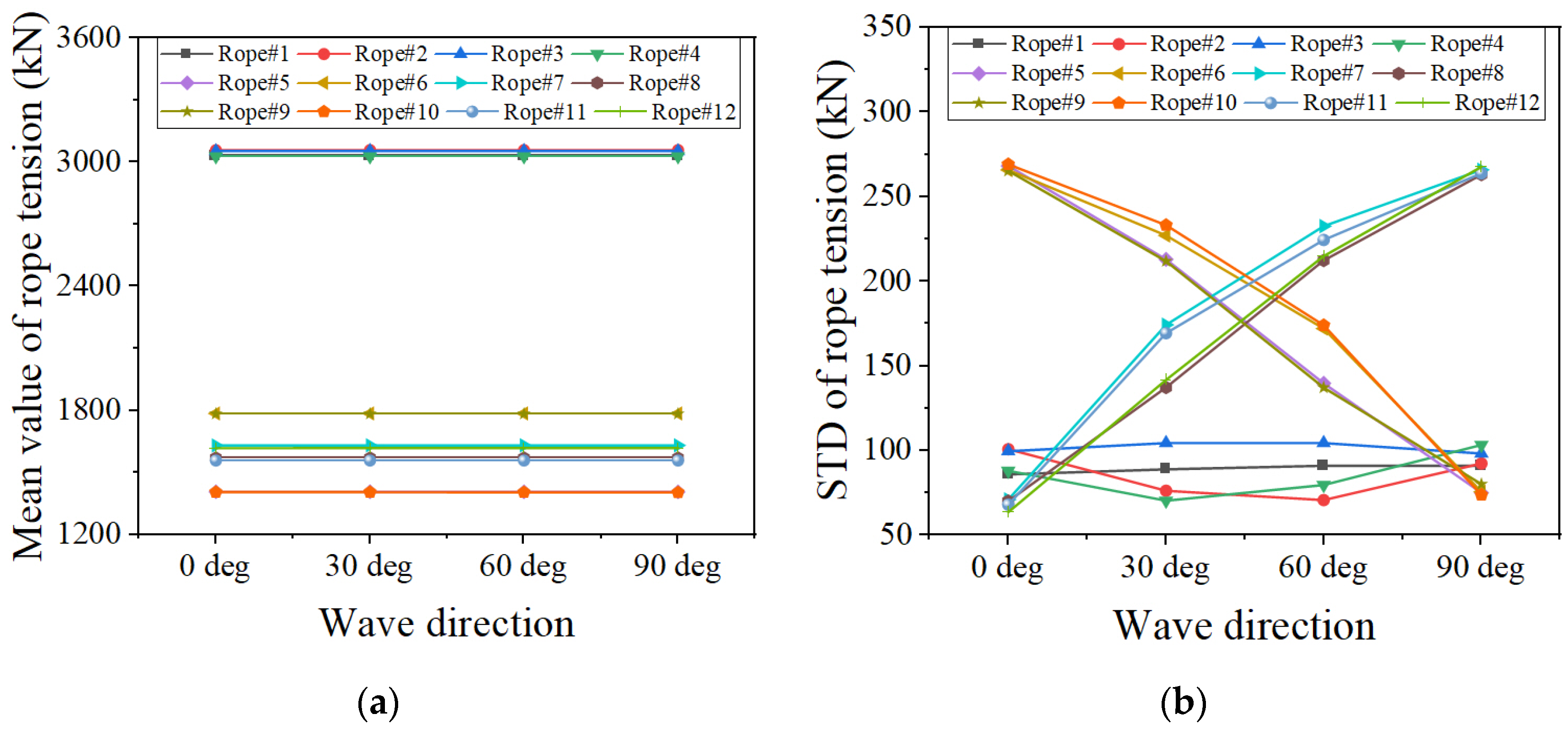
The analysis in the previous section shows that the tension of the lateral ropes is more sensitive to the wind and wave loads, among which, the tension of the four ropes along the wind and wave direction is more likely to change with the sea state. In order to further investigate the relationship between the ropes’ tension and waves, four different incident wave directions are selected in this section, namely 0 deg, 30 deg, 60 deg, and 90 deg, assuming that the wind keeps propagating along the +X direction. Figure 17 shows the statistical values of 12 suspension ropes tension with different wave directions under the load case of EC2.
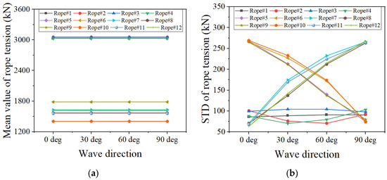
Figure 17.
Tension of suspension ropes under EC2: (a) mean value; (b) standard deviation.
First, the mean tension of each rope does not vary with the incident wave angle. Comparing the mean values among different ropes, it is observed that the mean tension of vertical ropes is much larger than that of the lateral ropes. The standard deviation diagram shows that the tension of different ropes varies at different magnitudes with the incident wave angle. For the vertical ropes, the standard deviation changes little with the wave direction. The standard deviation of the lateral ropes’ tension shows an obvious upward or downward trend with the increase in incident wave angle. It can be inferred from the above results that the mean value of the ropes’ tension is independent of the wave direction, whereas the magnitude of the tension variation is closely related to the direction of incident waves.
4.7. Cost-Effectiveness
The total steel mass of OC4-semisubmersible is 3852.2 t [26], and the semi-spar has a slightly smaller steel mass of 3337.3 t. Moreover, the semi-spar takes a braceless structure, while the OC4-semisubmersible is constituted by several columns and braces, which requires a more complicated fabrication, and the welded joints are more prone to fatigue damage.
In terms of power generation, Figure 18 compares the mean value and standard deviation of the power generated by the three floating wind turbines under the EC1 and EC2 conditions. It is observed that the semi-spar has a relatively higher average power generation with less fluctuation, which can be attributed to its satisfactory stability. The above comparison shows that the newly proposed floating wind turbine behaves better in power generation and presents superior overall economic benefits.
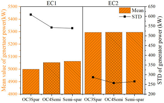
Figure 18.
Statistic values of generator power under EC2 and EC3.
5. Conclusions
In the present study, a novel semi-spar-type two-body floating platform applied for intermediate water depths is introduced. It consists of an upper floater and a hanging weight connected through 12 suspension ropes. It can be wet towed as a semisubmersible platform and has a large waterplane moment of inertia to increase stability and reduce transportation costs. After being anchored on site, the proposed semi-spar platform behaves as a spar platform with moderate draft and superior hydrodynamic characteristics. In the present study, the hydrostatic stability and motion responses of the proposed design are analyzed, and, hence, the design is systematically assessed. More specifically, the present study includes a stability check of the proposed design during wet towage and a fully coupled aero-hydro-servo-elastic simulation considering normal operation, 1-year recurrence, and 50-year recurrence sea conditions. Meanwhile, the motion responses of OC3-spar and OC4-semisubmersible under the same sea conditions are numerically simulated to provide a reference. The main conclusions from the numerical simulations are as follows:
- The proposed semi-spar design has sufficient restoring moments to maintain its balance during transportation. The static heeling angles of the design are 3.5° and 5° under normal and extreme conditions, respectively.
- The heave motion response and tower base fore–aft bending moment response of the semi-spar design are mainly dominated by waves, while the pitch motion response shows the influence of resonance; the proposed semi-spar design outperforms the OC3-spar and OC4-semisubmersible in surge and pitch under all load cases.
- The ultimate strength check indicates that the tension of the vertical suspension ropes is mainly determined by the hanging weight and has less fluctuation, while the tension of the lateral suspension ropes parallel with the propagation direction is highly sensitive to wind and wave conditions.
The present study highlights an innovative design of a semi-spar platform and shows its superior hydrodynamic performance and convenient offshore transportation. Considering this study is a preliminary effort for the authors to improve such an innovative design of the floating platform, further studies employing wave basin tests and prototype examinations are planned. As the offshore wind is moving toward larger capacities, the application of a semi-spar foundation to a 10 MW+ wind turbine is also being considered.
Author Contributions
Conceptualization, Q.C. and D.C.; methodology, Q.C. and N.Y.; software, Q.C.; writing—original draft preparation, Q.C.; writing—review and editing, D.C. and W.L.; supervision, D.C. All authors have read and agreed to the published version of the manuscript.
Funding
This research was funded by the Shenzhen Science and Technology Innovation Commission, grant number WDZC20200819174646001, and Guangdong Basic and Applied Basic Research Foundation, grant number 2022B1515130006.
Institutional Review Board Statement
Not applicable.
Informed Consent Statement
Not applicable.
Data Availability Statement
All data included in this study are available upon request.
Conflicts of Interest
Ni Yang was employed by the China Power Engineering Consulting Group Corporation Limited and Wei Li was employed by the Powerchina Huadong Engineering Corporation Limited. The remaining authors declare that the research was conducted in the absence of any commercial or financial relationships that could be construed as a potential conflict of interest.
References
- Bahaj, A.S.; Myers, L.E. Fundamentals applicable to the utilisation of marine current turbines for energy production. Renew. Energy 2003, 28, 2205–2211. [Google Scholar] [CrossRef]
- Rodríguez-Pérez, Á.M.; Rodríguez, C.A.; Márquez-Rodríguez, A.; Mancera, J.J.C. Viability Analysis of Tidal Turbine Installation Using Fuzzy Logic: Case Study and Design Considerations. Axioms 2023, 12, 778. [Google Scholar] [CrossRef]
- Timilsina, G.R.; Cornelis van Kooten, G.; Narbel, P.A. Global wind power development: Economics and policies. Energy Policy 2013, 61, 642–652. [Google Scholar] [CrossRef]
- GWEC. Global Offshore Wind Report 2022; Global Wind Energy Council: Brussels, Belgium, 2022. [Google Scholar]
- Jiang, Z.; Wen, B.; Chen, G.; Xiao, L.; Li, J.; Peng, Z.; Tian, X. Feasibility studies of a novel spar-type floating wind turbine for moderate water depths: Hydrodynamic perspective with model test. Ocean Eng. 2021, 233, 109070. [Google Scholar] [CrossRef]
- Cao, Q.; Xiao, L.; Cheng, Z.; Liu, M.; Wen, B. Operational and extreme responses of a new concept of 10MW semi-submersible wind turbine in intermediate water depth: An experimental study. Ocean Eng. 2020, 217, 108003. [Google Scholar] [CrossRef]
- Zhang, L.; Shi, W.; Karimirad, M.; Michailides, C.; Jiang, Z. Second-order hydrodynamic effects on the response of three semisubmersible floating offshore wind turbines. Ocean Eng. 2020, 207, 107371. [Google Scholar] [CrossRef]
- Rahman, M.; Ong, Z.C.; Chong, W.T.; Julai, S.; Khoo, S.Y. Performance enhancement of wind turbine systems with vibration control: A review. Renew. Sustain. Energy Rev. 2015, 51, 43–54. [Google Scholar] [CrossRef]
- Tüfekci, M.; Genel, Ö.E.; Tatar, A.; Tüfekci, E. Dynamic Analysis of Composite Wind Turbine Blades as Beams: An Analytical and Numerical Study. Vibration 2021, 4, 1–15. [Google Scholar] [CrossRef]
- Xie, F.; Aly, A.-M. Structural control and vibration issues in wind turbines: A review. Eng. Struct. 2020, 210, 110087. [Google Scholar] [CrossRef]
- Cao, Q.; Xiao, L.; Guo, X.; Liu, M. Second-order responses of a conceptual semi-submersible 10 MW wind turbine using full quadratic transfer functions. Renew. Energy 2020, 153, 653–668. [Google Scholar] [CrossRef]
- Cao, Q.; Xiao, L.; Cheng, Z.; Liu, M. Dynamic responses of a 10 MW semi-submersible wind turbine at an intermediate water depth: A comprehensive numerical and experimental comparison. Ocean Eng. 2021, 232, 109138. [Google Scholar] [CrossRef]
- Cutler, J.; Bashir, M.; Yang, Y.; Wang, J.; Loughney, S. Preliminary development of a novel catamaran floating offshore wind turbine platform and assessment of dynamic behaviours for intermediate water depth application. Ocean Eng. 2022, 258, 111769. [Google Scholar] [CrossRef]
- Jonkman, J.; Matha, D. Quantitative Comparison of the Responses of Three Floating Platforms; National Renewable Energy Lab. (NREL): Golden, CO, USA, 2010.
- Liu, Y.; Li, S.; Yi, Q.; Chen, D. Developments in semi-submersible floating foundations supporting wind turbines: A comprehensive review. Renew. Sustain. Energy Rev. 2016, 60, 433–449. [Google Scholar] [CrossRef]
- Zhao, Z.; Shi, W.; Wang, W.; Qi, S.; Li, X. Dynamic analysis of a novel semi-submersible platform for a 10 MW wind turbine in intermediate water depth. Ocean Eng. 2021, 237, 109688. [Google Scholar] [CrossRef]
- Stiesdal. The TetraSpar Full-Scale Demonstration Project. Available online: https://www.stiesdal.com/offshore/the-tetraspar-full-scale-demonstration-project/ (accessed on 28 April 2023).
- Bredmose, H.; Stolpe, M.; Pegalajar-Jurado, A.; Laugesen, K.; Jensen, B.; Borg, M.; Rønby, J.; Orszaghova, J. From pre-design to operation: Outlook and first results of the FloatStep project. In Proceedings of the EERA DeepWind 2020 Conference, Trondheim, Norway, 15–17 January 2020. [Google Scholar]
- Borg, M.; Walkusch Jensen, M.; Urquhart, S.; Andersen, M.T.; Thomsen, J.B.; Stiesdal, H. Technical Definition of the TetraSpar Demonstrator Floating Wind Turbine Foundation. Energies 2020, 13, 4911. [Google Scholar] [CrossRef]
- ESTEYCO. TELWIND Project. Available online: https://www.esteyco.com/projects/telwind/ (accessed on 10 December 2022).
- Dankelmann, S.; Visser, B.; Gupta, N.; Serna, J.; Counago, B.; Urruchi, Á.; Fernández, J.L.; Cortés, C.; Guanche García, R.; Jurado, A. TELWIND-Integrated Telescopic tower Combined with an Evolved Spar Floating Substructure for Low-Cost Deep Water Offshore Wind and Next Generation of 10 MW+ Wind Turbines. In Proceedings of the Wind Europe, Hamburg, Germany, 27–29 September 2016. [Google Scholar]
- Armesto, J.A.; Jurado, A.; Guanche, R.; Couñago, B.; Urbano, J.; Serna, J. TELWIND: Numerical analysis of a floating wind turbine supported by a two bodies platform. In Proceedings of the International Conference on Offshore Mechanics and Arctic Engineering, Madrid, Spain, 17–22 June 2018; p. V010T009A073. [Google Scholar]
- Delahaye, T.; Franc, P.; Colmard, C.; Gentil, F. New pendular floater for offshore wind commercial farms. In Proceedings of the Offshore Mediterranean Conference and Exhibition, Ravenna, Italy, 27–29 March 2019. [Google Scholar]
- Ward, J.C.; Goupee, A.J.; Viselli, A.M.; Dagher, H.J. Experimental investigation into the dynamic behavior of a floating offshore wind turbine stabilized via a suspended counterweight. Ocean Eng. 2021, 228, 108906. [Google Scholar] [CrossRef]
- Ward, J.C.; Goupee, A.J.; Viselli, A.M.; Dagher, H.J. The Effect of Counterweight Mass and Line Stiffness on the Global Dynamic Performance of a Hanging-Mass Floating Offshore Wind Turbine. J. Offshore Mech. Arct. Eng. 2021, 143, 052001. [Google Scholar] [CrossRef]
- Robertson, A.; Jonkman, J.; Masciola, M.; Song, H.; Goupee, A.; Coulling, A.; Luan, C. Definition of the Semisubmersible Floating System for Phase II of OC4; National Renewable Energy Lab. (NREL): Golden, CO, USA, 2014.
- Jonkman, J. Definition of the Floating System for Phase IV of OC3; National Renewable Energy Lab. (NREL): Golden, CO, USA, 2010.
- Jonkman, J.; Butterfield, S.; Musial, W.; Scott, G. Definition of a 5-MW Reference wind Turbine for Offshore System Development; National Renewable Energy Lab. (NREL): Golden, CO, USA, 2009.
- Orcina Ltd. OrcaFlex User Manual: OrcaFlex Version 10.2 c; Orcina Ltd.: Ulverston, UK, 2018. [Google Scholar]
- Cummins, W. The Impulse Response Function and Ship Motions; David Taylor Model Basin: Washington, DC, USA, 1962. [Google Scholar]
- Wan, L.; Gao, Z.; Moan, T.; Lugni, C. Experimental and numerical comparisons of hydrodynamic responses for a combined wind and wave energy converter concept under operational conditions. Renew. Energy 2016, 93, 87–100. [Google Scholar] [CrossRef]
- Lee, C.; Newman, J. WAMIT User Manual, Version 7.0; WAMIT Inc.: Chestnut Hill, MA, USA, 2013. [Google Scholar]
- Foulhoux, L.; Bernitsas, M.M. Forces and Moments on a Small Body Moving in a 3-D Unsteady Flow (With Applications to Slender Structures). J. Offshore Mech. Arct. Eng. 1993, 115, 91–104. [Google Scholar] [CrossRef]
- Ma, S.; Xu, D.-k.; Duan, W.-y.; Chen, J.-k.; Liao, K.-p.; Wang, H. The numerical study of viscous drag force influence on low-frequency surge motion of a semi-submersible in storm sea states. Ocean Eng. 2020, 213, 107511. [Google Scholar] [CrossRef]
- Pierson, W.J., Jr.; Moskowitz, L. A proposed spectral form for fully developed wind seas based on the similarity theory of S. A. Kitaigorodskii. J. Geophys. Res. 1964, 69, 5181–5190. [Google Scholar] [CrossRef]
- IEC 61400-1; Wind Turbines—Part 1: Design Requirement. IEC: Geneva, Switzerland, 2005.
- Jonkman, B. Turbsim User’s Guide: Version 2.00.00; NREL: Washington, DC, USA, 2016.
- Zheng, X.; Lei, Y. Stochastic Response Analysis for a Floating Offshore Wind Turbine Integrated with a Steel Fish Farming Cage. Appl. Sci. 2018, 8, 1229. [Google Scholar] [CrossRef]
- Ramachandran, G.K.V.; Robertson, A.; Jonkman, J.M.; Masciola, M.D. Investigation of Response Amplitude Operators for Floating Offshore Wind Turbines. In Proceedings of the The Twenty-Third International Offshore and Polar Engineering Conference, Anchorage, Alaska, 30 June–5 July 2013. [Google Scholar]
- Collu, M.; Maggi, A.; Gualeni, P.; Rizzo, C.M.; Brennan, F. Stability requirements for floating offshore wind turbine (FOWT) during assembly and temporary phases: Overview and application. Ocean Eng. 2014, 84, 164–175. [Google Scholar] [CrossRef]
- DNV-OS-J103; Design of Floating Wind Turbine Structures. DNV: Geneva, Switzerland, 2013.
- Han, Y.; Le, C.; Ding, H.; Cheng, Z.; Zhang, P. Stability and dynamic response analysis of a submerged tension leg platform for offshore wind turbines. Ocean Eng. 2017, 129, 68–82. [Google Scholar] [CrossRef]
- Bureau Veritas Marine & Offshore. Classification and Certification of Floating Offshore wind Turbines; Bureau Veritas Marine & Offshore: Paris, France, 2019. [Google Scholar]
- DNV-OS-E301; Position Mooring. DNV: Paris, France, 2021.


Disclaimer/Publisher’s Note: The statements, opinions and data contained in all publications are solely those of the individual author(s) and contributor(s) and not of MDPI and/or the editor(s). MDPI and/or the editor(s) disclaim responsibility for any injury to people or property resulting from any ideas, methods, instructions or products referred to in the content. |
© 2024 by the authors. Licensee MDPI, Basel, Switzerland. This article is an open access article distributed under the terms and conditions of the Creative Commons Attribution (CC BY) license (https://creativecommons.org/licenses/by/4.0/).