
The Physical Behavior of Protected Coal Seams Based on Triaxial Unloading Conditions

Abstract
1. Introduction
2. Experimental Process
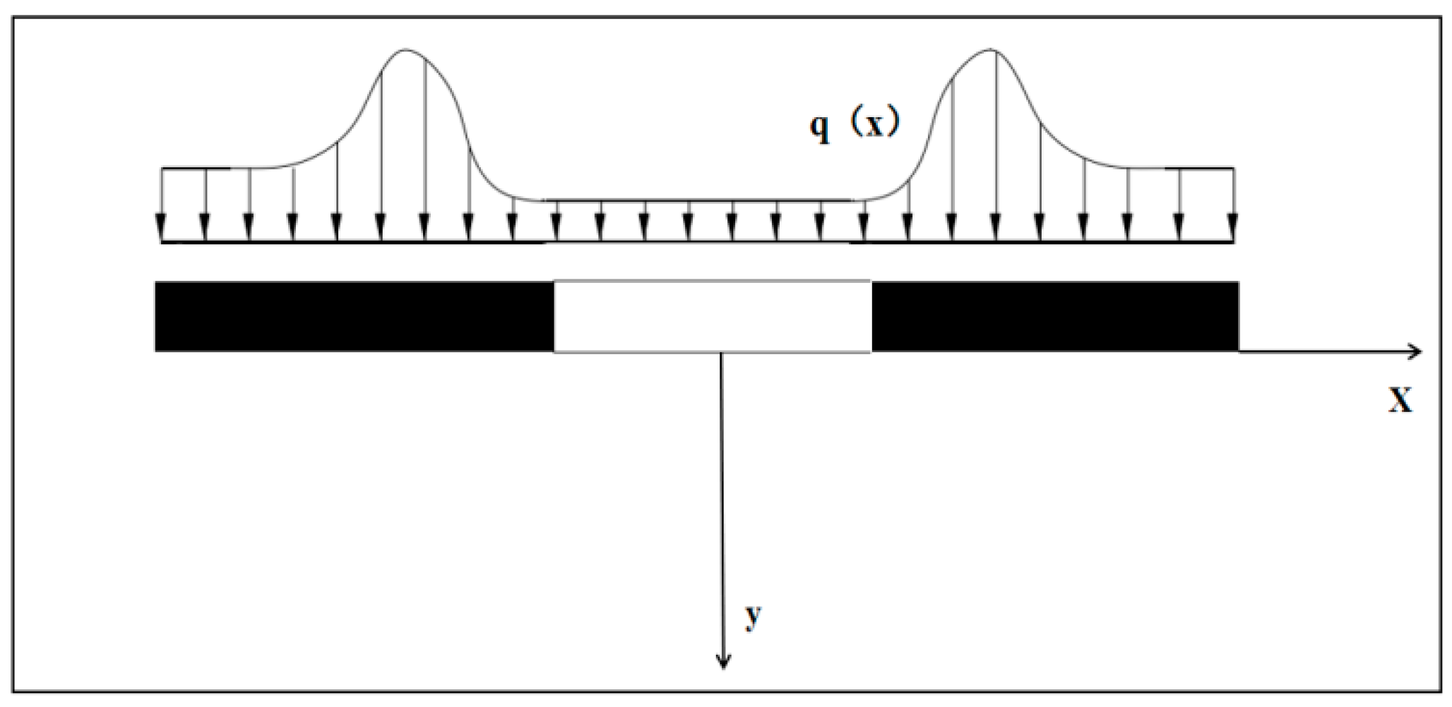
2.1. Theoretical Solution of Stress Distribution in the Bottom Plate of the Protective Layer Mining
2.2. Coal Sample Preparation
2.3. Test Scheme and Test Process
2.3.1. Test Scheme
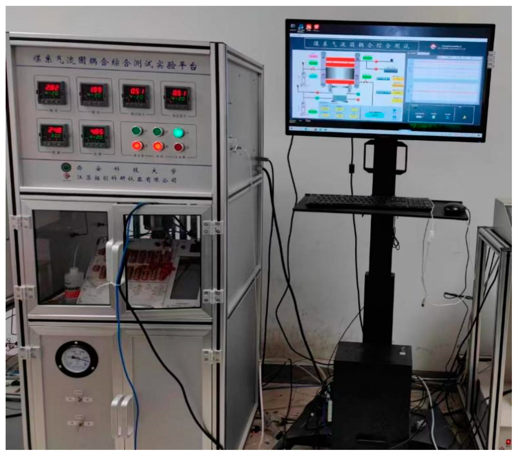
2.3.2. Test Process
3. Experimental Results
4. Discussion
4.1. Analysis of the Deformation Parameter Variation Characteristics
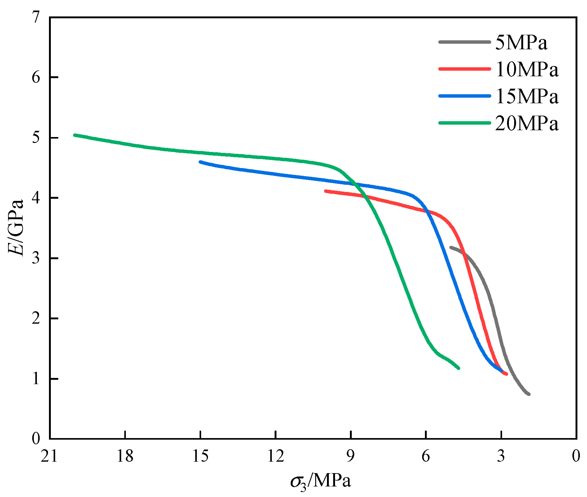
4.2. Deformation Modulus Analysis
4.3. Analysis of the Deterioration of the Deformation Modulus
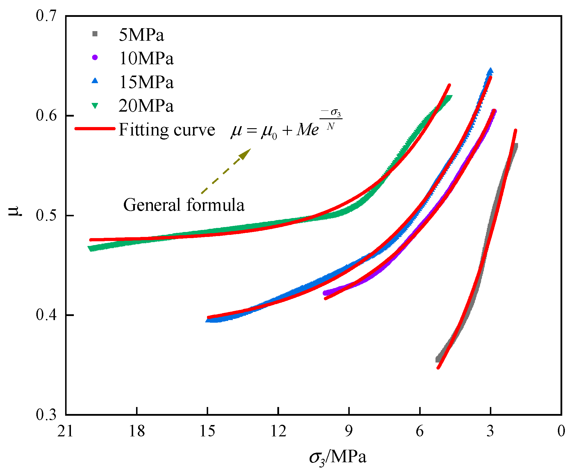
4.4. Analysis of Poisson’s Ratio Variation Characteristics
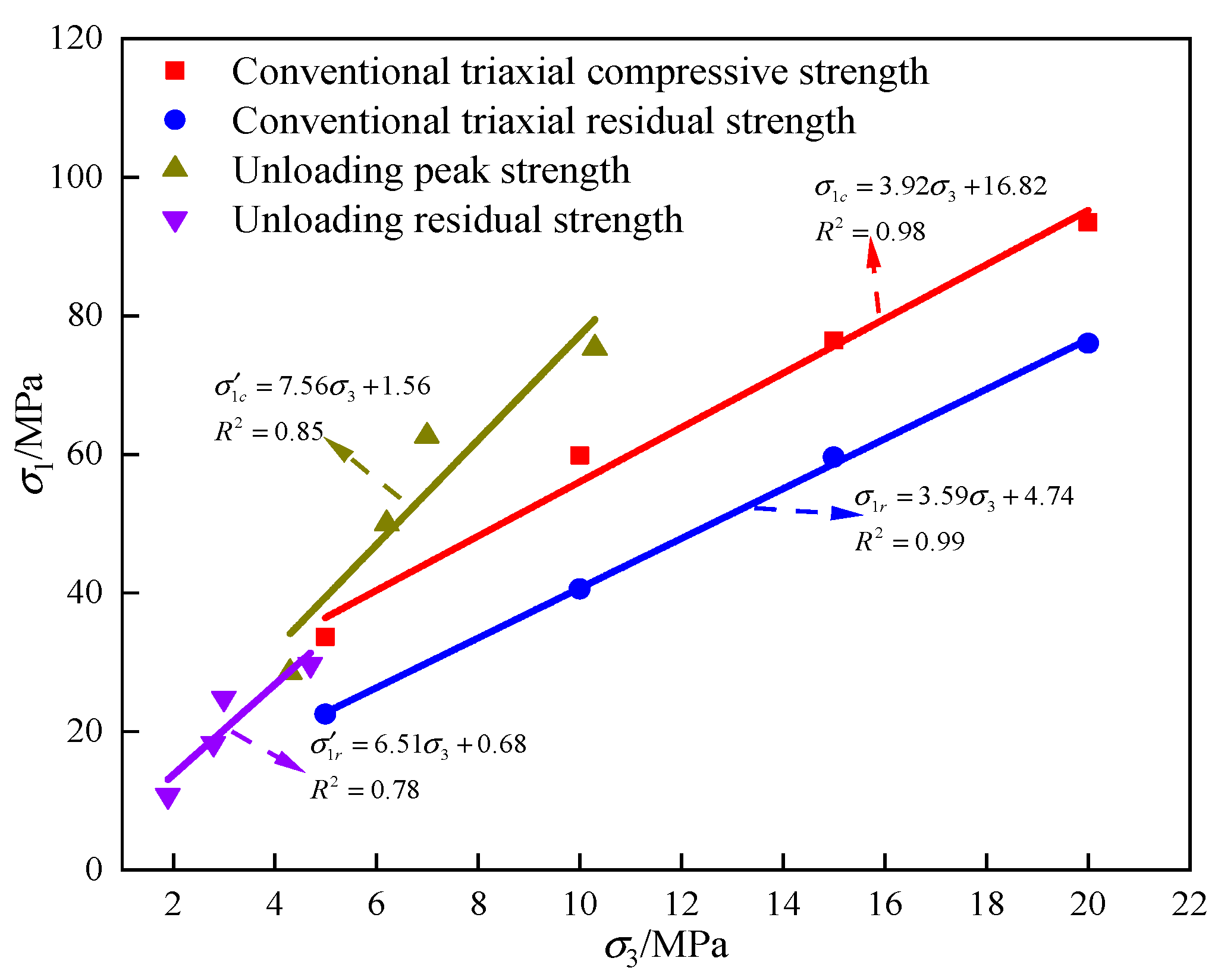
4.5. Analysis of the Strength Characteristics of Coal on the Unloading Path
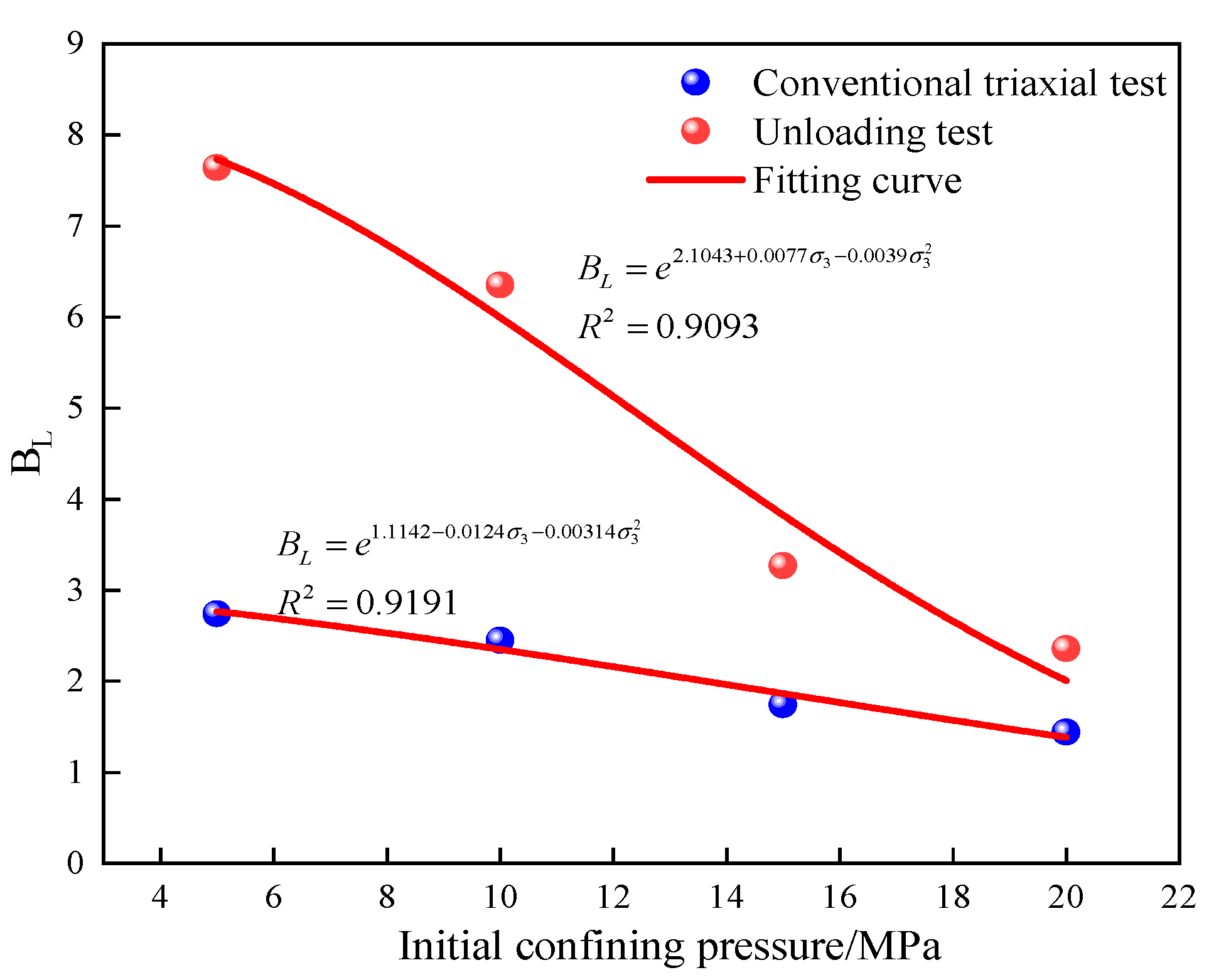
4.6. Analysis of the Brittleness and Ductility Transformation of the Coal Samples
5. Conclusions
- (i)
- Under the unloading path, the bias stress–axial strain curve showed a sudden upward trend after the beginning of unloading, and the slope of the curve increased suddenly, which was more obvious after the peripheral pressure exceeded 10 MPa, and the stress unloading before the peak accelerated the yielding of the specimen.
- (ii)
- Under the unloading test path, the deformation modulus of the coal samples decreased with decreasing enclosure pressure, while the damage factor and Poisson’s ratio increased with decreasing enclosure pressure.
- (iii)
- Compared to the conventional triaxial test, the cohesion at peak stress decreased by 93.41% and the angle of internal friction increased by 37.41% for the coal samples under unloading conditions. The residual cohesion decreased by 89.60% and the angle of internal friction increased by 37.44°.
- (iv)
- Compared to conventional triaxial test conditions, the brittleness indices of the coal samples under unloading conditions with an enclosing pressure of 5 MPa, 10 MPa, 15 MPa, and 20 MPa increased by 178.83%, 159.18%, 87.93%, and 63.89%, respectively. The results indicated that the larger the circumferential pressure, the smaller the difference in the brittleness index.
Author Contributions
Funding
Institutional Review Board Statement
Informed Consent Statement
Data Availability Statement
Conflicts of Interest
References
- Lin, H.; Ji, P.; Kong, X.; Li, S.; Long, H.; Xiao, T.; Li, B. Experimental study on the influence of gas pressure on CH4 adsorption-desorption-seepage and deformation characteristics of coal in the whole process under triaxial stress. Fuel 2023, 333, 126513. [Google Scholar] [CrossRef]
- Zhang, C.; Wang, P.; Wang, E.; Chen, D.; Li, C. Characteristics of coal resources in China and statistical analysis and preventive measures for coal mine accidents. Int. J. Coal Sci. Technol. 2023, 10, 22. [Google Scholar] [CrossRef]
- Liang, Y.; Yang, Y.; Guo, S.; Tian, F.; Wang, S. Combustion mechanism and control approaches of underground coal fires: A review. Int. J. Coal Sci. Technol. 2023, 10, 24. [Google Scholar] [CrossRef]
- Han, H.; Wang, H.; Zhang, Q.; Du, Y.; Wang, H.; Wang, H. Investigations of the effects of two typical jet crushing methods on the atomization and dust reduction performance of nozzles. Int. J. Coal Sci. Technol. 2023, 10, 50. [Google Scholar] [CrossRef]
- Wang, K.; Zhang, G.; Wang, Y.; Zhang, X.; Li, K.; Guo, W.; Du, F. A numerical investigation of hydraulic fracturing on coal seam permeability based on PFC-COMSOL coupling method. Int. J. Coal Sci. Technol. 2022, 9, 10. [Google Scholar] [CrossRef]
- Ranjith, P.; Zhao, J.; Ju, M.; De Silva, R.; Rathnaweera, T.; Bandara, A. Opportunities and Challenges in Deep Mining: A Brief Review. Engineering 2017, 3, 546–551. [Google Scholar] [CrossRef]
- Cheng, Z.; Qi, Q.; Li, H.; Zhang, L.; Liu, X. Evolution of the superimposed mining induced stress-fissure field under extracting of close distance coal seam group. J. China Coal Soc. 2016, 41, 367–375. [Google Scholar]
- Xie, H.; Zhao, X.; Liu, J.; Zhang, R.; Xue, D. Influence of different mining layouts on the mechanical properties of coal. Int. J. Min. Sci. Technol. 2012, 22, 749–755. [Google Scholar] [CrossRef]
- Zhang, L.; Huang, M.; Li, M.; Lu, S.; Yuan, X.; Li, J. Experimental Study on Evolution of Fracture Network and Permeability Characteristics of Bituminous Coal Under Repeated Mining Effect. Nat. Resour. Res. 2022, 31, 463–486. [Google Scholar] [CrossRef]
- Zhang, C.; Zhang, L. Permeability Characteristics of Broken Coal and Rock Under Cyclic Loading and Unloading. Nat. Resour. Res. 2019, 28, 1055–1069. [Google Scholar] [CrossRef]
- Zhao, T.; Zhang, P.; Xiao, Y.; Guo, W.; Zhang, Y.; Zhang, X. Master crack types and typical acoustic emission characteristics during rock failure. Int. J. Coal Sci. Technol. 2023, 10, 2. [Google Scholar] [CrossRef]
- Du, X.; Xue, J.; Ma, Q.; Chen, Z.; Zhan, K. Energy evolution characteristics of coal–rock composite bodies based on unidirectional load. Nat. Resour. Res. 2022, 31, 1647–1663. [Google Scholar] [CrossRef]
- Zhou, J.; Lin, H.; Jin, H.; Li, S.; Yan, Z.; Huang, S. Cooperative prediction method of gas emission from mining face based on feature selection and machine learning. Int. J. Coal Sci. Technol. 2022, 9, 51. [Google Scholar] [CrossRef]
- Ullah, B.; Cheng, Y.; Wang, L.; Yang, W.; Jiskani, M.; Hu, B. Experimental analysis of pore structure and fractal characteristics of soft and hard coals with same coalification. Int. J. Coal Sci. Technol. 2022, 9, 58. [Google Scholar] [CrossRef]
- Ji, P.; Lin, H.; Kong, X.; Li, S.; Hu, B.; Wang, P.; He, D.; Yang, S. Pore structure of low-permeability coal and its deformation characteristics during the adsorption–desorption of CH4/N2. Int. J. Coal Sci. Technol. 2023, 10, 51. [Google Scholar] [CrossRef]
- Wang, C.; Wang, H.; Elsworth, D.; Cui, G.; Li, B.; Zhou, M.; Li, W.; Zhang, J. Revaluating coal permeability-gas pressure relation under various gas pressure differential conditions. Int. J. Coal Sci. Technol. 2023, 10, 55. [Google Scholar] [CrossRef]
- Zou, Q.; Zhan, J.; Wang, X.; Huang, Z. Influence of nanosized magnesia on the hydration of borehole-sealing cements prepared using different methods. Int. J. Coal Sci. Technol. 2023, 10, 66. [Google Scholar] [CrossRef]
- Hou, P.; Xue, Y.; Gao, F.; Wang, S.; Jiao, X.; Zhu, C. Numerical Evaluation on Stress and Permeability Evolution of Overlying Coal Seams for Gas Drainage and Gas Disaster Elimination in Protective Layer Mining. Min. Metall. Explor. 2022, 39, 1027–1043. [Google Scholar] [CrossRef]
- Ren, S.; Tao, Z.; He, M.; Li, M.; Sui, Q. Numerical simulation study on shear resistance of anchorage joints considering tensile–shear fracture criterion of 2G-NPR bolt. Int. J. Coal Sci. Technol. 2023, 10, 58. [Google Scholar] [CrossRef]
- Yuan, Y.; Chen, Z.; Zhang, X.; Wang, Z. Intermediate coal pillar instability and permeability evolution in extremely thin protective seam by auger mining. Arab. J. Geosci. 2019, 12, 322. [Google Scholar] [CrossRef]
- Yu, S.; Zhu, W.; Niu, L. Experimental and numerical evaluation on debonding of fully grouted rockbolt under pull-out loading. Int. J. Coal Sci. Technol. 2022, 9, 8. [Google Scholar] [CrossRef]
- Jin, H.; Yang, Z. Study on Reasonable Layout of Upper Protective Layer for Prevention Rock Burst under Coal Seam Group with Close Quarters Conditions. Shock. Vib. 2021, 2021, 6139935. [Google Scholar] [CrossRef]
- Ji, P.; Lin, H.; Kong, X.; Li, S.; Cai, Y.; Wang, R.; Tian, Y.; Zhao, T. Experimental study on enhanced coal seam gas extraction by uniform pressure/pulse pressure N2 injection. Fuel 2023, 351, 128988. [Google Scholar] [CrossRef]
- Deng, D.; Wang, H.; Xie, L.; Wang, Z.; Song, J. Experimental study on the interrelation of multiple mechanical parameters in overburden rock caving process during coal mining in longwall panel. Int. J. Coal Sci. Technol. 2023, 10, 47. [Google Scholar] [CrossRef]
- Huo, B.; Fan, Z.; Lu, Y.; Duan, Z.; Jing, X.; Xie, Z. Similarity simulation study on permeability of protected coal seam volumetric strain during mining protective coal seam. Coal Sci. Technol. 2018, 46, 19–26. [Google Scholar]
- Qin, S.; Lin, H.; Yang, S.; Wei, Z. A mathematical model for parameter setting in discrete element numerical simulation. Int. J. Coal Sci. Technol. 2023, 10, 87. [Google Scholar] [CrossRef]
- Ma, D.; Duan, H.; Li, Q.; Wu, J.; Zhon, W.; Huang, Z. Water–rock two-phase flow model for water inrush and instability of fault rocks during mine tunnelling. Int. J. Coal Sci. Technol. 2023, 10, 77. [Google Scholar] [CrossRef]
- Liu, X.; Chen, H.; Liu, B.; Wang, S.; Liu, Q.; Luo, Y.; Luo, J. Experimental and numerical investigation on failure characteristics and mechanism of coal with different water contents. Int. J. Coal Sci. Technol. 2023, 10, 49. [Google Scholar] [CrossRef]
- Lei, W. Study on the effect and mechanism of rock burst prevention by pressure relief of underlying coal and rock in protective coal seam mining. Xi’an Univ. Sci. Technol. 2021, 58–81. [Google Scholar]
- Cheng, X. Mechanical effect and application of mining relief-pressure for soft rock protective layer mining in deep strong outburst coal seam. Anhui Univ. Sci. Technol. 2019, 64–90. [Google Scholar]
- Yin, G.; Li, M.; Wang, J.; Xu, J.; Li, W. Mechanical behavior and permeability evolution of gas infiltrated coals during protective layer mining. Int. J. Rock. Mech. Min. 2015, 80, 292–301. [Google Scholar] [CrossRef]
- Ding, K.; Wang, L.; Wang, W.; Li, Z.; Jiang, C.; Ren, B.; Wang, S. Experimental Study on Gas Seepage Characteristics of Axially Unloaded Coal under Different Confining Pressures and Gas Pressures. Processes 2022, 10, 1055. [Google Scholar] [CrossRef]
- Li, Q.; Liang, Y.; Zou, Q. Seepage and Damage Evolution Characteristics of Gas-Bearing Coal under Different Cyclic Loading-Unloading Stress Paths. Processes 2018, 6, 190. [Google Scholar] [CrossRef]
- Cheng, W.; Cui, G.; Tan, Y.; Elsworth, D.; Wang, C.; Yang, C.; Chen, T.; Jiang, C. A multi-layer nanocased model to explain the U-shaped evolution of shale gas permeability at constant confining pressure. Fuel 2024, 359, 130478. [Google Scholar] [CrossRef]
- Cui, G.; Tan, Y.; Chen, T.; Feng, X.; Elsworth, D.; Pan, Z.; Wang, C. Multidomain two-phase flow model to study the impacts of hydraulic fracturing on shale gas production. Energy Fuels 2020, 34, 4273–4288. [Google Scholar] [CrossRef]
- Cui, G.; Feng, X.; Pan, Z.; Chen, T.; Liu, J.; Elsworth, D.; Tan, Y.; Wang, C. Impact of shale matrix mechanical interactions on gas transport during production. J. Pet. Sci. Eng. 2020, 184, 106524. [Google Scholar] [CrossRef]
- Cui, G.; Liu, J.; Wei, M.; Shi, R.; Elsworth, D. Why shale permeability changes under variable effective stresses: New insights. Fuel 2018, 213, 55–71. [Google Scholar] [CrossRef]
- Xu, L.; Fan, C.; Luo, M.; Li, S.; Han, J.; Fu, X.; Xiao, B. Elimination mechanism of coal and gas outburst based on geo-dynamic system with stress–damage–seepage interactions. Int. J. Coal Sci. Technol. 2023, 10, 74. [Google Scholar] [CrossRef]
- Cheng, Z. Study on Crack Evolution and Permeability Characteristic of Protective Coal Seam Mining in Close Coal Seams Group; China University of Mining & Technology: Beijing, China, 2018. [Google Scholar]
- Huang, R.; Huang, D. Experimental research on affection laws of unloading rates on mechanical properties of Jinping marble under high geostress. Chin. J. Rock. Mech. Eng. 2010, 29, 21–33. [Google Scholar]
- Gao, C.; Xu, J.; He, P.; Liu, J. Study on mechanical properties of marble under loading and unloading conditions. Chin. J. Rock. Mech. Eng. 2005, 24, 456–460. [Google Scholar]
- Zhu, Z.; Wei, L.; Li, J.; Meng, Q.; Sui, B.; Zhang, Z. Deformation evolution and dissipated energy characteristics of marble under pre-peak unloading conditions. J. China Coal Soc. 2020, 45, 181–190. [Google Scholar]
- Liu, Q.; Liu, K.; Lu, X.; Zhu, J. Study of mechanical properties of raw coal under high stress with triaxial unloading. Chin. J. Rock. Mech. Eng. 2014, 33, 3429–3438. [Google Scholar]
- Xie, H.; Gao, M.; Fu, C.; Lu, Y.; Yang, M.; Hu, J.; Yang, B.G. Mechanical behavior of brittle-ductile transition in rocks at different depths. J. China Coal Soc. 2021, 46, 701–715. [Google Scholar]
- Zhang, C.; Yu, J.; Bai, Y.; Cao, W.; Zhang, S.; Guo, Z. Statistical damage constitutive model of rock brittle-ductile transition based on strength theory. Chin. J. Rock. Mech. Eng. 2023, 42, 1–10. [Google Scholar]
- Zhang, C.; Bai, Y.; An, Y.; Wang, H.; Zeng, X. A new method for evaluating rock brittle characteristics based on full stress-strain curve. J. Highw. Transp. Res. Dev. 2021, 38, 63–72. [Google Scholar]


| Fitting Equation | Initial Confining Pressure/MPa | A | B | D0 | R2 |
|---|---|---|---|---|---|
| 5 | 3.07038 | 5.60142 | −1.31807 | 0.97580 | |
| 10 | 6.12552 | 1.45330 | −0.00254 | 0.97893 | |
| 15 | 3.57130 | 2.13161 | 0.01971 | 0.97187 | |
| 20 | 5.02598 | 2.72875 | 0.01770 | 0.96784 |
| Fitting Equation | Initial Confining Pressure/MPa | M | N | μ0 | R2 |
|---|---|---|---|---|---|
| 5 | 0.68169 | 3.18992 | 0.21442 | 0.9913 | |
| 10 | 0.44648 | 4.52193 | 0.36765 | 0.9984 | |
| 15 | 0.51624 | 4.28636 | 0.38208 | 0.9979 | |
| 20 | 0.72289 | 3.10297 | 0.47438 | 0.9853 |
Disclaimer/Publisher’s Note: The statements, opinions and data contained in all publications are solely those of the individual author(s) and contributor(s) and not of MDPI and/or the editor(s). MDPI and/or the editor(s) disclaim responsibility for any injury to people or property resulting from any ideas, methods, instructions or products referred to in the content. |
© 2024 by the authors. Licensee MDPI, Basel, Switzerland. This article is an open access article distributed under the terms and conditions of the Creative Commons Attribution (CC BY) license (https://creativecommons.org/licenses/by/4.0/).
Share and Cite
Chen, Z.; Xue, J.; Guo, L.; Cheng, R.; Yang, Q.; Xiao, J. The Physical Behavior of Protected Coal Seams Based on Triaxial Unloading Conditions. Sustainability 2024, 16, 922. https://doi.org/10.3390/su16020922
Chen Z, Xue J, Guo L, Cheng R, Yang Q, Xiao J. The Physical Behavior of Protected Coal Seams Based on Triaxial Unloading Conditions. Sustainability. 2024; 16(2):922. https://doi.org/10.3390/su16020922
Chicago/Turabian StyleChen, Zhiheng, Junhua Xue, Lanlan Guo, Renhui Cheng, Quanlin Yang, and Jian Xiao. 2024. "The Physical Behavior of Protected Coal Seams Based on Triaxial Unloading Conditions" Sustainability 16, no. 2: 922. https://doi.org/10.3390/su16020922
APA StyleChen, Z., Xue, J., Guo, L., Cheng, R., Yang, Q., & Xiao, J. (2024). The Physical Behavior of Protected Coal Seams Based on Triaxial Unloading Conditions. Sustainability, 16(2), 922. https://doi.org/10.3390/su16020922