
Modular Open Chamber Stand for Biomass Densification Using the Example of Miscanthus × Giganteus Greef Et Deu


Abstract
1. Introduction
2. Materials and Methods
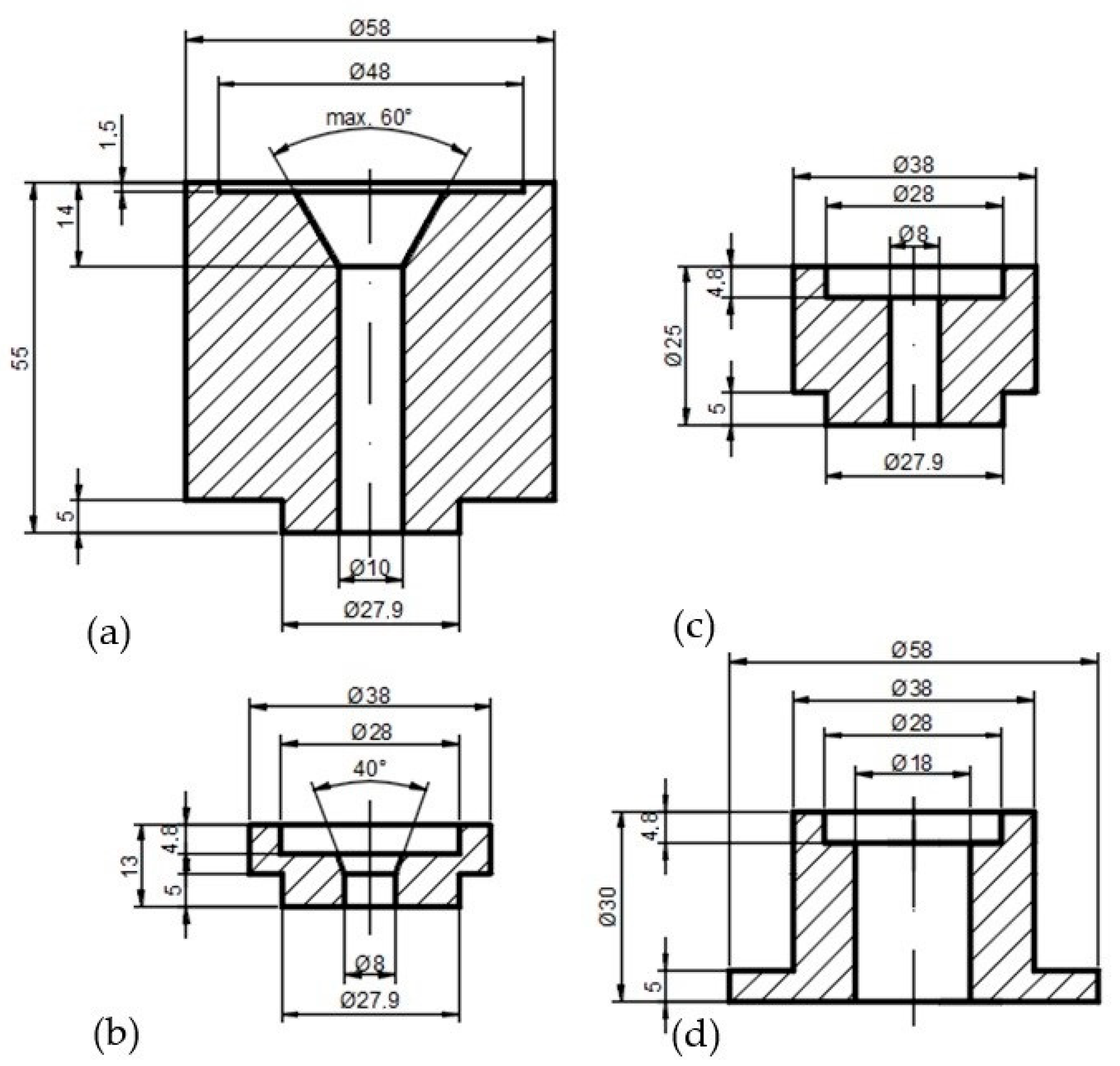
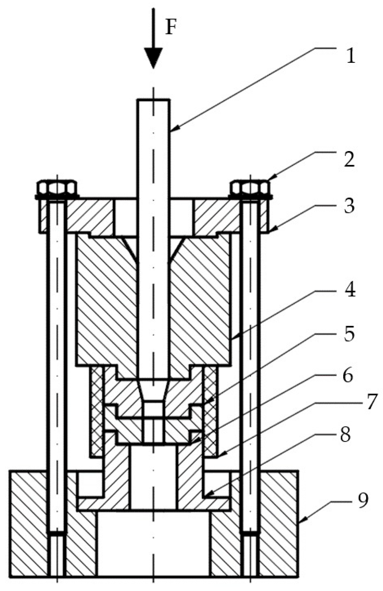
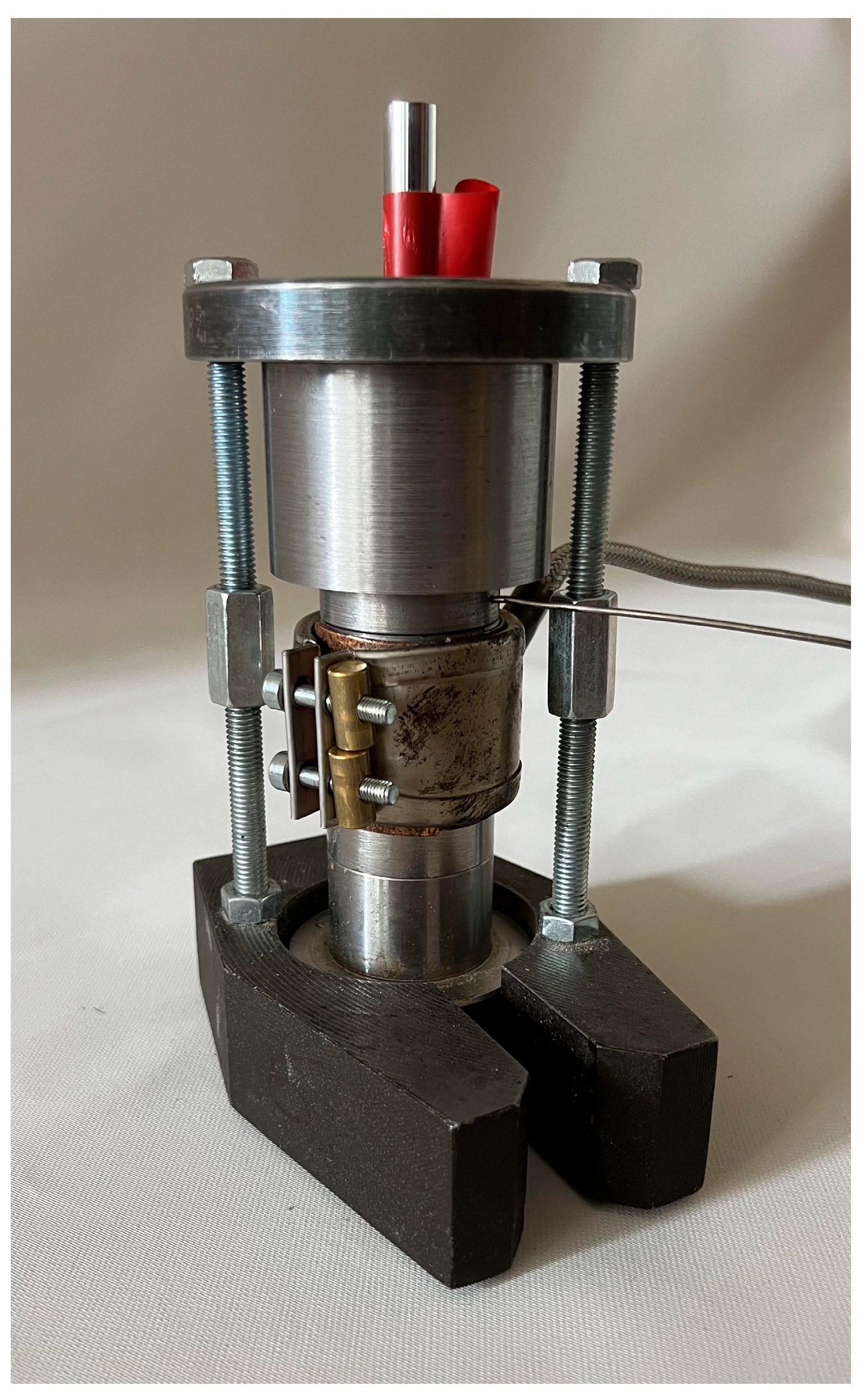
2.1. Conception of Open Chamber Test Stand
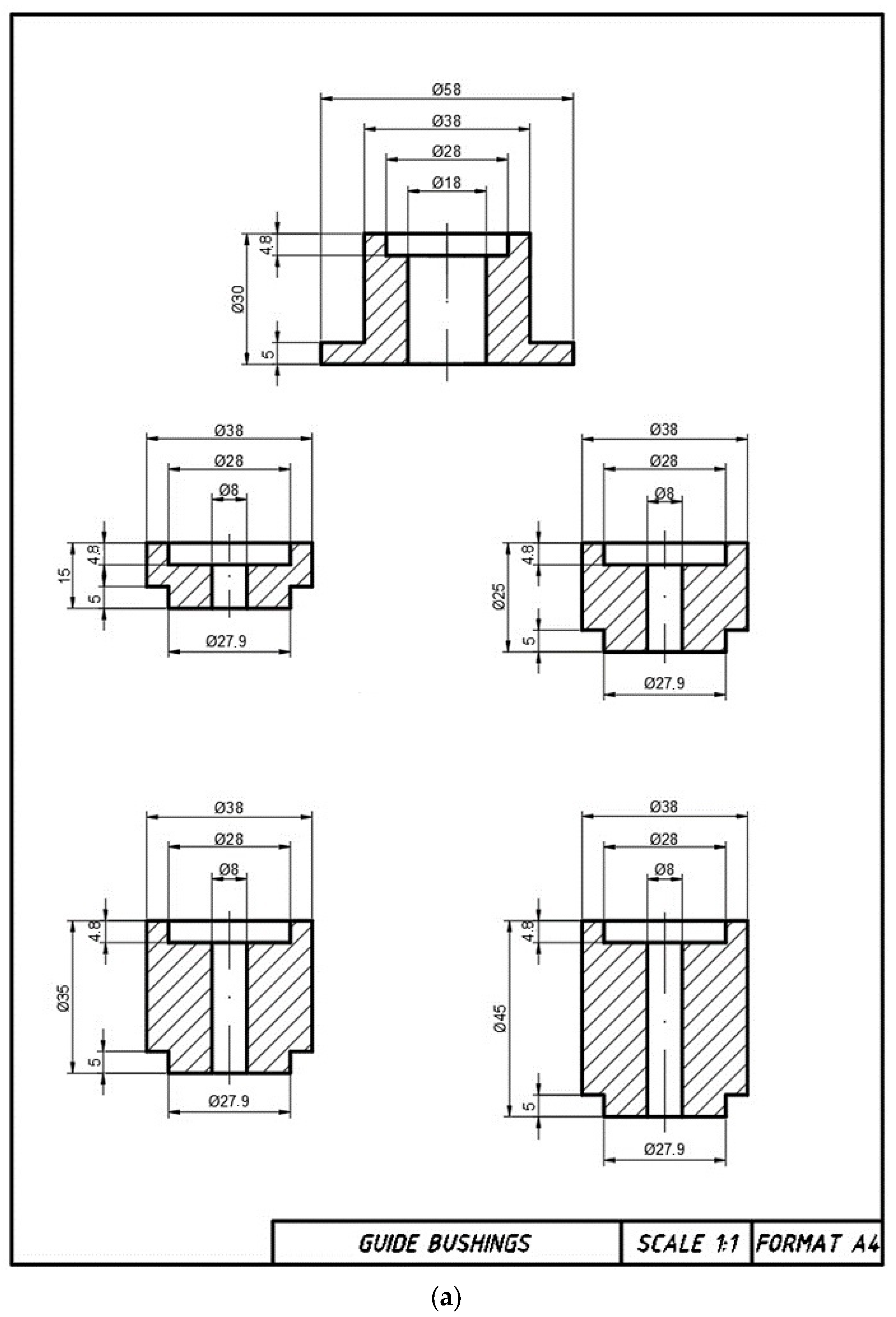
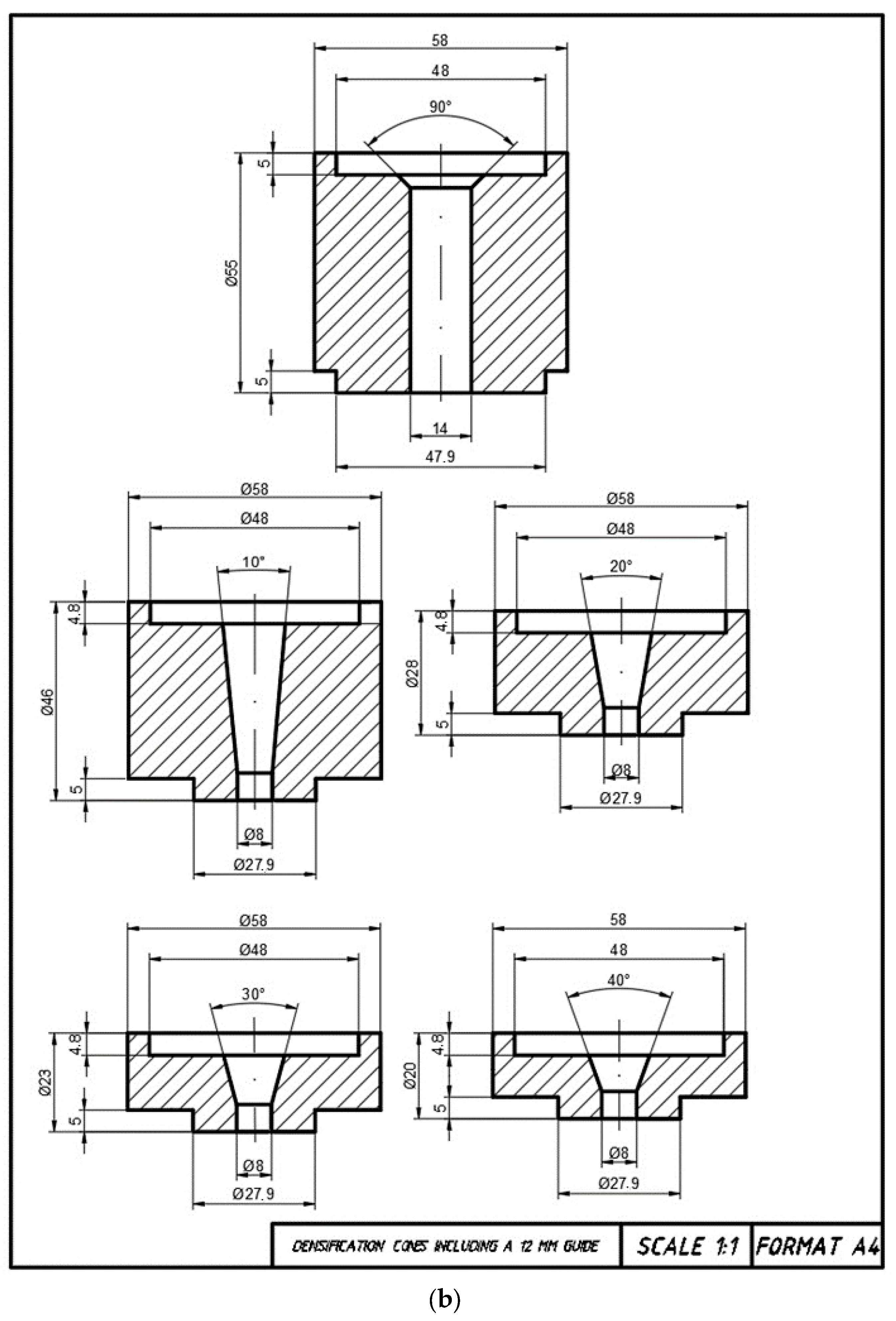
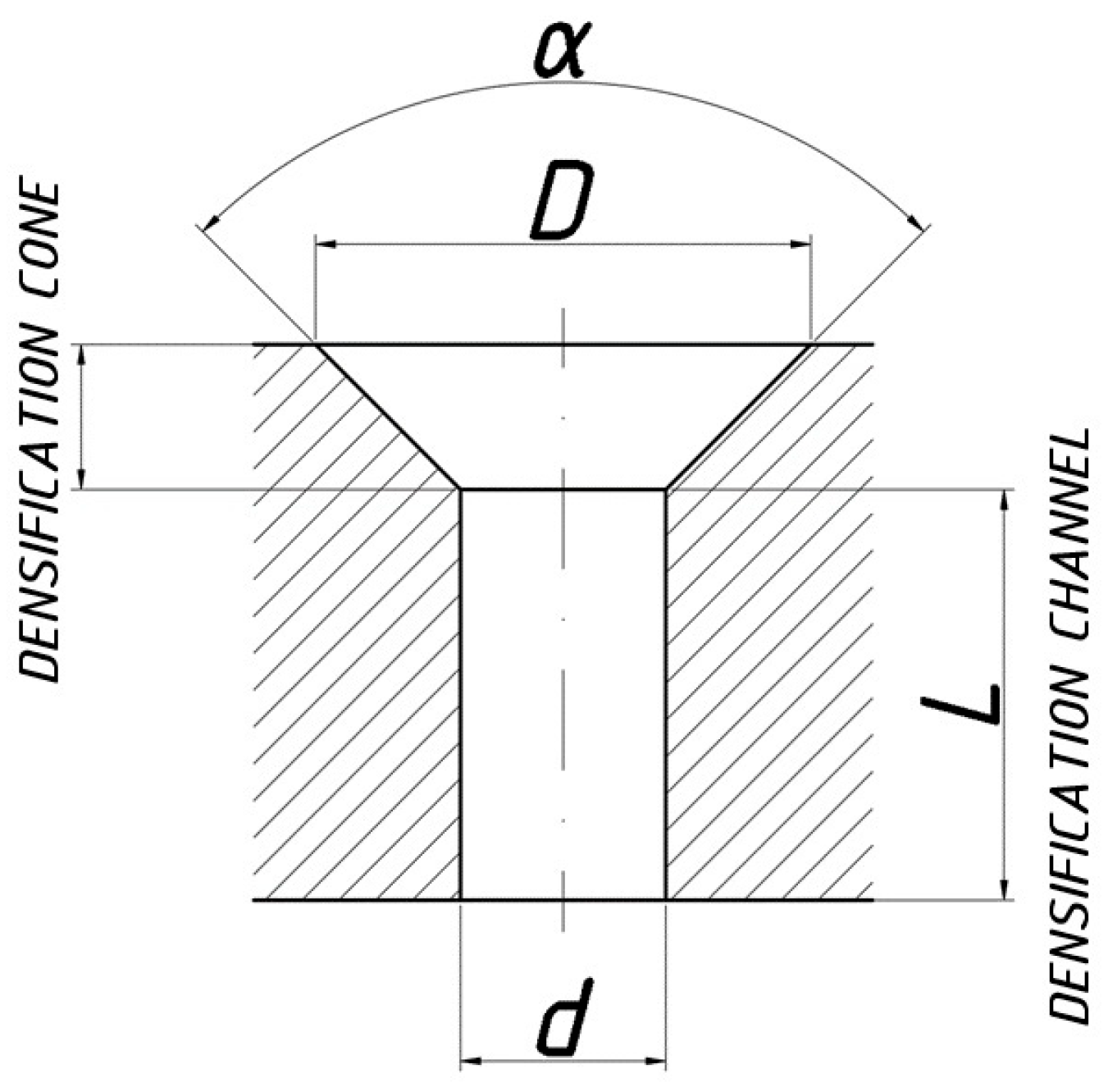
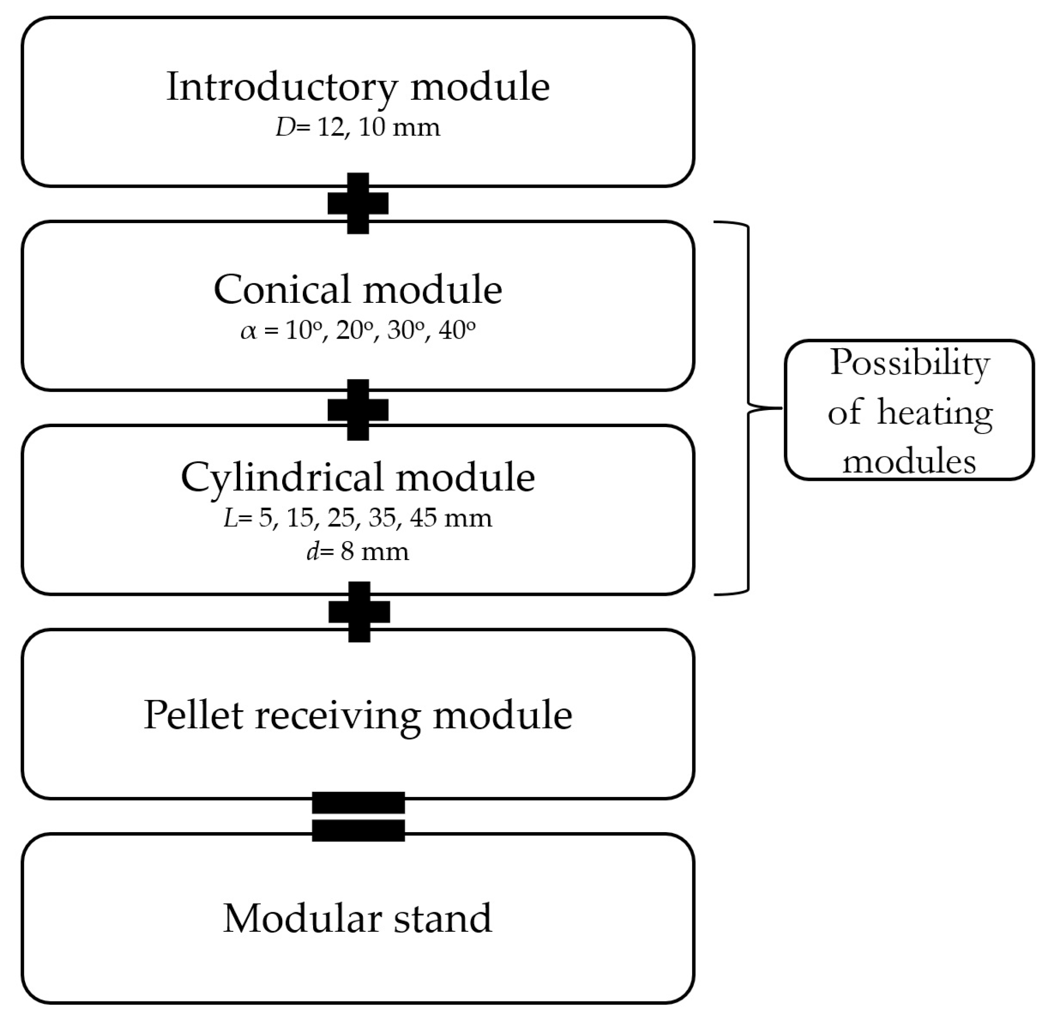
- An introduction module—a bushing into which a dose of material is introduced and in which a piston moves. The piston movement is caused by a testing machine. During densification of the material dose, the piston reaches the lower surface of the insertion bushing without entering the conical section (this approximates the real conditions of the pelletizing process, where the roller rolls on the die surface and forces the material dose into the conical sections of the densification channels). This bush has an inner diameter equal to the diameter D of the conical section;
- A pellet receiving module—a bushing with an inside diameter larger than the cylindrical section of the densification channel d, which is located directly below. The pellet exiting the channel undergoes a partial spring back and can be collected, described and forwarded for further testing;
- The case, which connects the above modules and is also mounted in the tester’s holder;
- A heater, thermocouple and temperature control module for the thickening channel.
2.2. Testing
2.2.1. Material
2.2.2. Test Parameters
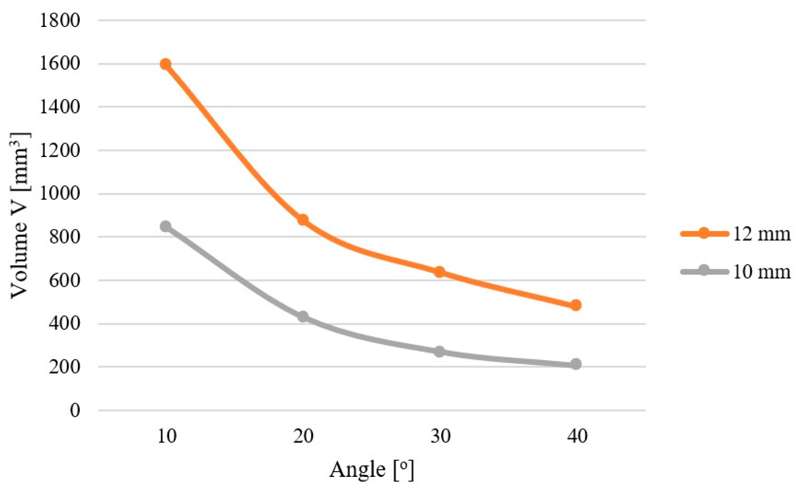
- 13% material moisture content, 100 °C process temperature, 12 mm inlet diameter conical section,
- 13% material moisture content, 100 °C process temperature, 10 mm inlet diameter conical section,
2.2.3. Determination of the Specific Density of the Test Pellet
2.2.4. Selection of Particle Size Composition PSD
2.2.5. Moisturisation and Moisture Content Measurement
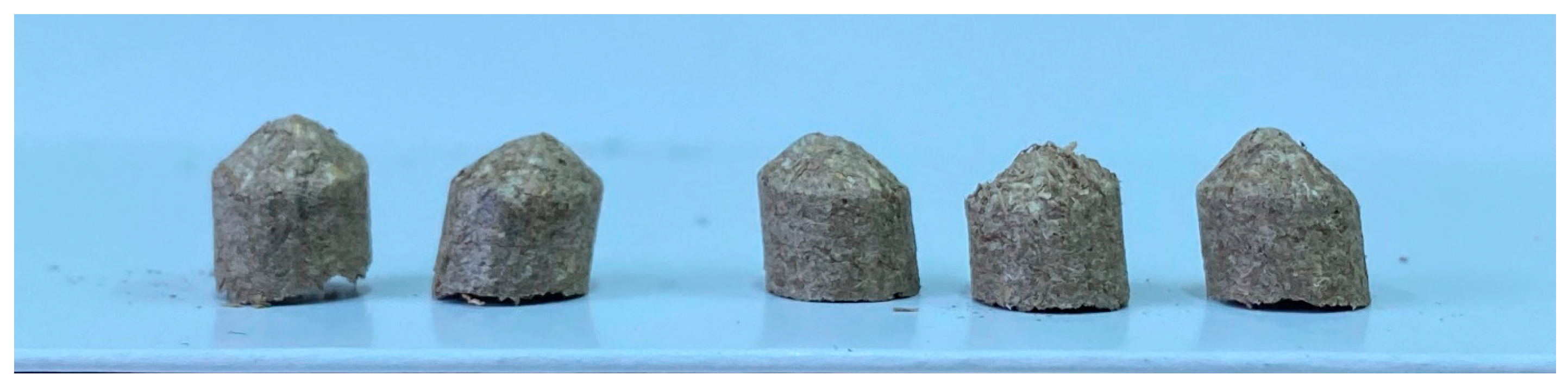
3. Results
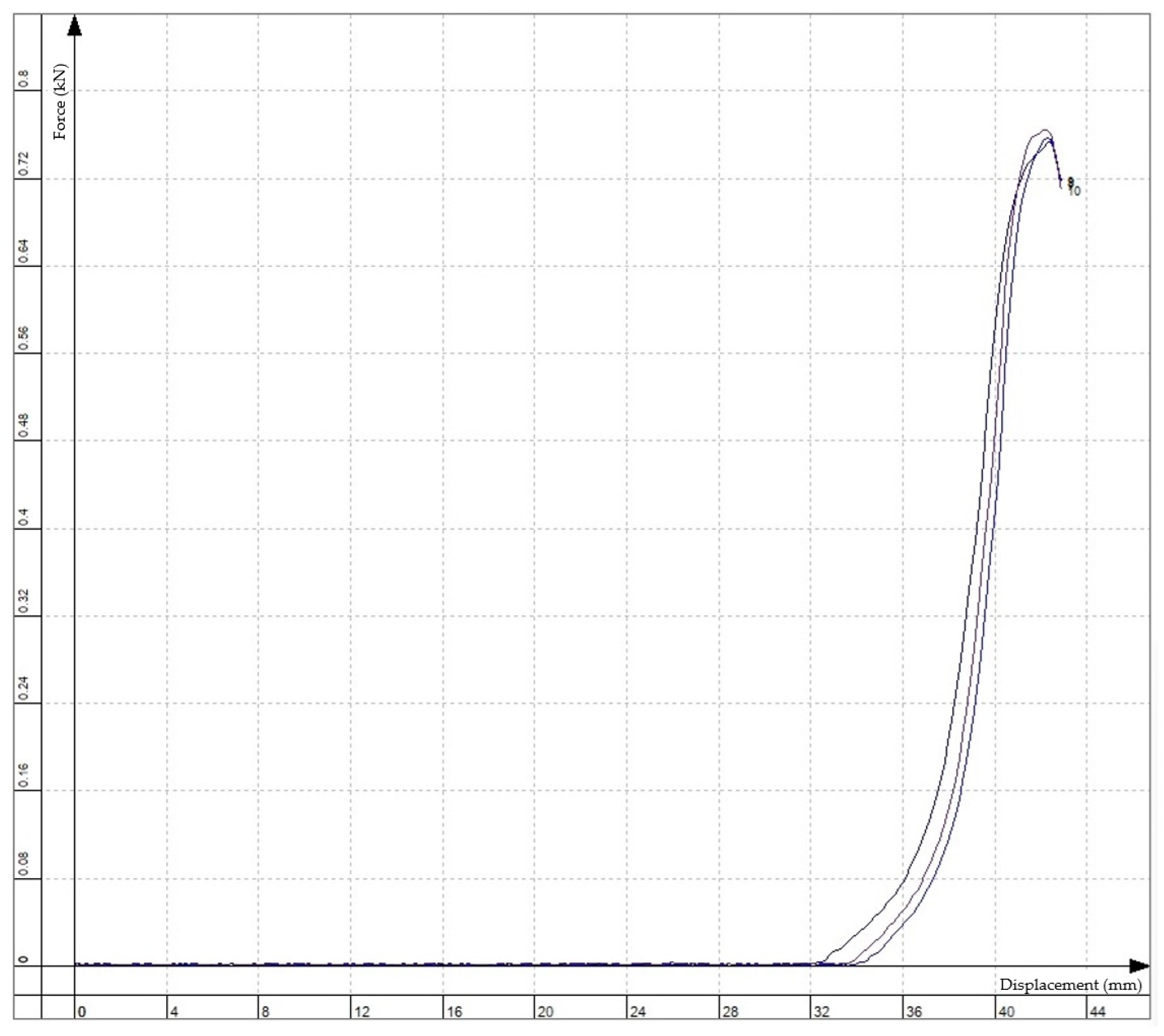
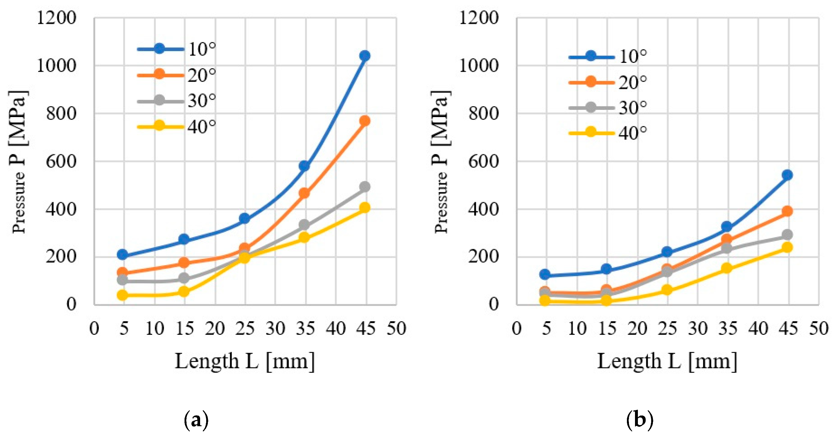
3.1. Pressure
3.2. Density
4. Discussion and Conclusions
Author Contributions
Funding
Institutional Review Board Statement
Informed Consent Statement
Data Availability Statement
Conflicts of Interest
Appendix A

References
- Mitrus, M.; Tydman, K.; Milanowski, M.; Soja, J.; Lewko, P.; Kupryaniuk, K.; Wójtowicz, A. Influence of the Forming Die Design on Processing and Physical Properties of Gluten-Free Crisps. Agric. Eng. 2024, 28, 87–96. [Google Scholar] [CrossRef]
- Paszkowski, J.; Domański, M.; Caban, J.; Zarajczyk, J.; Pristavka, M.; Findura, P. The Use of Refuse Derived Fuel (RDF) in the Power Industry. Agric. Eng. 2020, 24, 83–90. [Google Scholar] [CrossRef]
- Mani, S.; Sokhansanj, S.; Bi, X.; Turhollow, A. Economics of producing fuel pellets from biomass. Appl. Eng. Agric. 2006, 22, 421–426. [Google Scholar] [CrossRef]
- Jasiczek, F.; Kwaśniewski, D. Analysis of Production Technology of Wood Briquettes, Including Costs and Distribution. Agric. Eng. 2020, 24, 35–45. [Google Scholar] [CrossRef]
- Mykhailov, Y.; Zadosna, N.; Ihnatiev, Y.; Kutsenko, A.; Hutsol, T.; Grotkiewicz, K.; Firman, Y.; Horetska, I. Practical Potential of Grain Impurities in the Processing of Sunflower Oil Raw Materials in the Oil and Fat Industry. Agric. Eng. 2022, 26, 13–23. [Google Scholar] [CrossRef]
- Gendek, A.; Aniszewska, M.; Owoc, D.; Tamelová, B.; Malaťák, J.; Velebil, J.; Krilek, J. Physico-mechanical and energy properties of pellets made from ground walnut shells, coniferous tree cones and their mixtures. Renew. Energy 2023, 211, 248–258. [Google Scholar] [CrossRef]
- Križan, P.; Šooš, L.; Matúš, M.; Beniak, J.; Svátek, M. Research of significant densification parameters influence on final briquettes quality. Wood Res. 2015, 60, 301–316. [Google Scholar]
- Nurek, T.; Gendek, A.; Dąbrowska, M. Influence of the Die Height on the Density of the Briquette Produced from Shredded Logging Residues. Materials 2021, 14, 3698. [Google Scholar] [CrossRef] [PubMed]
- Taulbee, D.; Patil, D.P.; Honaker, R.Q.; Parekh, B.K. Briquetting of Coal Fines and Sawdust Part I: Binder and Briquetting-Parameters Evaluations. Int. J. Coal Prep. Util. 2009, 29, 1–22. [Google Scholar] [CrossRef]
- Križan, P. Research of factors influencing the quality of wood briquets. Acta Montan. Slovaca 2007, 12, 223–230. [Google Scholar]
- Križan, P.; Šooš, Ľ.; Matúš, M. Optimalisation of briquetting machine pressing chamber geometry. Mach. Des. 2010, 1259, 19–24. [Google Scholar]
- Smith, I.E.; Probert, S.D.; Stokes, R.E.; Hansford, R.J. The briquetting of wheat straw. J. Agric. Eng. Res. 1977, 22, 105–111. [Google Scholar] [CrossRef]
- Nielsen, S.; Mandø, M.; Rosenørn, A. Review of die design and process parameters in the biomass pelleting process. Powder Technol. 2020, 364, 971–985. [Google Scholar] [CrossRef]
- Nielsen, N.P.K.; Gardner, D.J.; Poulsen, T.; Felby, C. Importance of temperature, moisture content, and species for the conversion process of wood residues into fuel pellets. Wood Fiber Sci. 2009, 41, 414–425. [Google Scholar]
- Gendek, A.; Aniszewska, M.; Malaťák, J.; Velebil, J. Evaluation of selected physical and mechanical properties of briquettes produced from cones of three coniferous tree species. Biomass Bioenergy 2018, 117, 173–179. [Google Scholar] [CrossRef]
- Kraszkiewicz, A.; Niedziółka, I.; Parafiniuk, S.; Sprawka, M.; Dula, M. Assessment of Selected Physical Characteristics of the English Ryegrass (Lolium Perenne L.) Waste Biomass Briquettes. Agric. Eng. 2019, 23, 21–30. [Google Scholar] [CrossRef]
- Domański, M.; Paszkowski, J.; Sergey, O.; Zarajczyk, J.; Siłuch, D. Analysis of Energy Properties of Granulated Plastic Fuels and Selected Biofuels. Agric. Eng. 2020, 24, 1–9. [Google Scholar] [CrossRef]
- Puig-Arnavat, M.; Shang, L.; Sárossy, Z.; Ahrenfeldt, J.; Henriksen, U.B. From a single pellet press to a bench scale pellet mill—Pelletizing six different biomass feedstocks. Fuel Process. Technol. 2016, 142, 27–33. [Google Scholar] [CrossRef]
- Crawford, N.C.; Ray, A.E.; Yancey, N.A.; Nagle, N. Evaluating the pelletization of ‘pure’ and blended lignocellulosic biomass feedstocks. Fuel Process. Technol. 2015, 140, 46–56. [Google Scholar] [CrossRef]
- Križan, P. The Effects of the Pressing Chamber Design Parameters on the Quality of Extrusions. In Biomass Compaction; Springer International Publishing: Cham, Switzerland, 2022; pp. 65–87. [Google Scholar] [CrossRef]
- Winter, E. Fundamental Considerations for Preparing Densified Refuse-Derived Fuel; Municipal Environmental Research Laboratory: Cincinnati, OH, USA, 1981. [Google Scholar]
- Mišljenović, N.; Čolović, R.; Vukmirović, Đ.; Brlek, T.; Bringas, C.S. The effects of sugar beet molasses on wheat straw pelleting and pellet quality. A comparative study of pelleting by using a single pellet press and a pilot-scale pellet press. Fuel Process. Technol. 2016, 144, 220–229. [Google Scholar] [CrossRef]
- Hu, J.; Lei, T.; Shen, S.; Zhang, Q. Specific Energy Consumption Regression and Process Parameters Optimization in Wet-Briquetting of Rice Straw at Normal Temperature. Bioresources 2012, 8, 663–675. [Google Scholar] [CrossRef]
- Wu, K.; Shi, S.J.; Wang, Y.L.; Bin Peng, B. FEA Simulation of Extruding Feed through Die Hole in Pelleting Process. Appl. Mech. Mater. 2011, 109, 350–354. [Google Scholar] [CrossRef]
- Współczynnik Sprężu. Available online: http://pelet.atlibron.com/ (accessed on 5 May 2023).
- Holm, J.K.; Henriksen, U.B.; Hustad, J.E.; Sørensen, L.H. Toward an Understanding of Controlling Parameters in Softwood and Hardwood Pellets Production. Energy Fuels 2006, 20, 2686–2694. [Google Scholar] [CrossRef]
- Heffner, L.E.; Pfost, H.B. Gelatinization during pelleting. Tec.-Molit. 2012, 26, 102–104. [Google Scholar]
- Butler, J.L.; McColly, H.F. Factors Affecting the Pelleting of Hay; Michigan State University of Agriculture and Applied Science, Department of Agricultural Engineering: East Lansing, MI, USA, 1958. [Google Scholar]
- Tumuluru, J.S.; Sokhansanj, S.; Lim, C.J.; Bi, T.; Lau, A.; Melin, S.; Sowlati, T.; Oveisi, E. Quality of Wood Pellets Produced in British Columbia for Export. Appl. Eng. Agric. 2010, 26, 1013–1020. [Google Scholar] [CrossRef]
- Hill, B.; Pulkinen, D.A. A Study of Factors Affecting Pellet Durability and Pelleting Efficiency in the Production of Dehydrated Alfalfa Pellets; A Special Report; Agriculture Development Fund: Tisdale, SK, Canada, 1988. [Google Scholar]
- EN ISO 17225-1:2021; Biopaliwa Stałe—Specyfikacje Paliw i Klasy—Część 1: Wymagania Ogólne. ISO: Geneva, Switzerland, 2021.
- Moll, L.; Wever, C.; Völkering, G.; Pude, R. Increase of Miscanthus Cultivation with New Roles in Materials Production—A Review. Agronomy 2020, 10, 308. [Google Scholar] [CrossRef]
- Gubišová, M.; Gubiš, J.; Žofajová, A.; Mihálik, D.; Kraic, J. Enhanced in vitro propagation of Miscanthus × giganteus. Ind. Crops Prod. 2013, 41, 279–282. [Google Scholar] [CrossRef]
- Schwarz, H. Miscanthus sinensis ‘giganteus’ production on several sites in Austria. Biomass Bioenergy 1993, 5, 413–419. [Google Scholar] [CrossRef]
- Flaig, H.; Mohr, H. (Eds.) Energie aus Biomasse; Springer: Berlin/Heidelberg, Germany, 1993. [Google Scholar] [CrossRef]
- Osman, A.I.; Ahmed, A.T.; Johnston, C.R.; Rooney, D.W. Physicochemical characterization of miscanthus and its application in heavy metals removal from wastewaters. Environ. Prog. Sustain. Energy 2018, 37, 1058–1067. [Google Scholar] [CrossRef]
- Osman, A.I.; Abdelkader, A.; Johnston, C.R.; Morgan, K.; Rooney, D.W. Thermal Investigation and Kinetic Modeling of Lignocellulosic Biomass Combustion for Energy Production and Other Applications. Ind. Eng. Chem. Res. 2017, 56, 12119–12130. [Google Scholar] [CrossRef]
- Styks, J.; Wróbel, M.; Frączek, J.; Knapczyk, A. Effect of Compaction Pressure and Moisture Content on Quality Parameters of Perennial Biomass Pellets. Energies 2020, 13, 1859. [Google Scholar] [CrossRef]
- Styks, J.; Knapczyk, A.; Łapczyńska-Kordon, B. Effect of Compaction Pressure and Moisture Content on Post-Agglomeration Elastic Springback of Pellets. Materials 2021, 14, 879. [Google Scholar] [CrossRef]
- EN ISO 16559:2014-09; Biopaliwa Stałe—Terminologia, Definicje i Określenia. ISO: Geneva, Switzerland, 2014.
- EN ISO 17225-2:2021-10; Biopaliwa Stałe—Specyfikacje Paliw i Klasy—Część 2: Klasy Peletów Drzewnych. ISO: Geneva, Switzerland, 2021.
- EN ISO 17225-6:2021-12; Biopaliwa Stałe—Specyfikacje Paliw i Klasy—Część 6: Klasy Peletów Niedrzewnych. ISO: Geneva, Switzerland, 2021.
- Nielsen, S.K.; Mandø, M. Experimental and numerical investigation of die designs in biomass pelleting and the effect on layer formation in pellets. Biosyst. Eng. 2020, 198, 185–197. [Google Scholar] [CrossRef]
- Skonecki, S.; Kulig, R.; Łysiak, G.; Laskowski, J.; Różyło, R. The effect of material moisture content and chamber diameter on compaction parameters of meadow grass. J. Res. Appl. Agric. Eng. 2013, 58, 149–153. [Google Scholar]
- Larsson, S.H.; Rudolfsson, M.; Nordwaeger, M.; Olofsson, I.; Samuelsson, R. Effects of moisture content, torrefaction temperature, and die temperature in pilot scale pelletizing of torrefied Norway spruce. Appl. Energy 2013, 102, 827–832. [Google Scholar] [CrossRef]
- Rhén, C.; Gref, R.; Sjöström, M.; Wästerlund, I. Effects of raw material moisture content, densification pressure and temperature on some properties of Norway spruce pellets. Fuel Process. Technol. 2005, 87, 11–16. [Google Scholar] [CrossRef]
- Lisowski, A.; Dąbrowska-Salwin, M.; Ostrowska-Ligęza, E.; Nawrocka, A.; Stasiak, M.; Świętochowski, A.; Klonowski, J.; Sypuła, M.; Lisowska, B. Effects of the biomass moisture content and pelleting temperature on the pressure-induced agglomeration process. Biomass Bioenergy 2017, 107, 376–383. [Google Scholar] [CrossRef]
- Knapczyk, A.; Francik, S.; Wójcik, A.; Bednarz, G. Influence of Storing Miscanthus × gigantheus on Its Mechanical and Energetic Properties; Springer: Cham, Switzerland, 2018; pp. 651–660. [Google Scholar] [CrossRef]
- Wagner, M.; Mangold, A.; Lask, J.; Petig, E.; Kiesel, A.; Lewandowski, I. Economic and environmental performance of miscanthus cultivated on marginal land for biogas production. GCB Bioenergy 2019, 11, 34–49. [Google Scholar] [CrossRef]
- Moiceanu, G.; Voicu, P.; Paraschiv, G.; Voicu, G. Behaviour of miscanthus at cutting shear with straight knives with different edge angles. Environ. Eng. Manag. J. 2017, 16, 1203–1209. [Google Scholar] [CrossRef]
- Francik, S.; Knapik, P.; Łapczyńska-Kordon, B.; Francik, R.; Ślipek, Z. Values of Selected Strength Parameters of Miscanthus × Giganteus Stalk Depending on Water Content and Internode Number. Materials 2022, 15, 1480. [Google Scholar] [CrossRef] [PubMed]
- Czeczko, R. Uprawy wybranych roślin energetycznych. Energia odnawialna w nauce i praktyce. In Proceedings of the EKOENERGIA ‘2012: Energia odnawialna w Nauce i Praktyce, Lublin, Poland, 26–27 October 2012; pp. 170–172. [Google Scholar]
- Kieć, J. Wady i zalety roślin energetycznych. In Energetyka Alternatywna; Wydawnictwo Dolnośląskiej Wyższej Szkoły Przedsiębiorczości i Techniki w Polkowicach: Polkowice, Poland, 2011. [Google Scholar]
- Wróbel, M. Zagęszczalność i Kompaktowalność Biomasy Celulozowej; Polskie Towarzystwo Inzynierii Rolniczej: Kraków, Poland, 2019. [Google Scholar]
- Lewandowski, I.; Clifton-Brown, J.C.; Scurlock, J.M.O.; Huisman, W. Miscanthus: European experience with a novel energy crop. Biomass Bioenergy 2000, 19, 209–227. [Google Scholar] [CrossRef]
- Greef, J.M.; Deuter, M. Syntaxonomy of Miscanthus × giganteus Greef et Deu. Angew. Bot. 1993, 67, 87–90. [Google Scholar]
- Xue, S.; Lewandowski, I.; Wang, X.; Yi, Z. Assessment of the production potentials of Miscanthus on marginal land in China. Renew. Sustain. Energy Rev. 2016, 54, 932–943. [Google Scholar] [CrossRef]
- Feng, Q.; Chaubey, I.; Engel, B.; Cibin, R.; Sudheer, K.P.; Volenec, J. Marginal land suitability for switchgrass, Miscanthus and hybrid poplar in the Upper Mississippi River Basin (UMRB). Environ. Model. Softw. 2017, 93, 356–365. [Google Scholar] [CrossRef]
- Cudjoe, E.; Hunsen, M.; Xue, Z.; Way, A.E.; Barrios, E.; Olson, R.A.; Hore, M.J.; Rowan, S.J. Miscanthus Giganteus: A commercially viable sustainable source of cellulose nanocrystals. Carbohydr. Polym. 2017, 155, 230–241. [Google Scholar] [CrossRef]
- Tumuluru, J.S.; Wright, C.T.; Hess, J.R.; Kenney, K.L. A review of biomass densification systems to develop uniform feedstock commodities for bioenergy application. Biofuels Bioprod. Biorefining 2011, 5, 683–707. [Google Scholar] [CrossRef]
- Serrano, C.; Monedero, E.; Lapuerta, M.; Portero, H. Effect of moisture content, particle size and pine addition on quality parameters of barley straw pellets. Fuel Process. Technol. 2011, 92, 699–706. [Google Scholar] [CrossRef]
- Gageanu, I.; Cujbescu, D.; Persu, C.; Tudor, P.; Cardei, P.; Matache, M.; Vladut, V.; Biris, S.; Voicea, I.; Ungureanu, N. Influence of Input and Control Parameters on the Process of Pelleting Powdered Biomass. Energies 2021, 14, 4104. [Google Scholar] [CrossRef]
- Boryga, M.; Kołodziej, P. Reverse Engineering in Modeling Agricultural Products. Agric. Eng. 2022, 26, 105–117. [Google Scholar] [CrossRef]
- Jewiarz, M.; Mudryk, K.; Wróbel, M.; Frączek, J.; Dziedzic, K. Parameters Affecting RDF-Based Pellet Quality. Energies 2020, 13, 910. [Google Scholar] [CrossRef]
- Manouchehrinejad, M.; Yue, Y.; de Morais, R.L.; Souza, L.; Singh, H.; Mani, S. Densification of Thermally Treated Energy Cane and Napier Grass. BioEnergy Res. 2018, 11, 538–550. [Google Scholar] [CrossRef]
- Jackson, J.; Turner, A.; Mark, T.; Montross, M. Densification of biomass using a pilot scale flat ring roller pellet mill. Fuel Process. Technol. 2016, 148, 43–49. [Google Scholar] [CrossRef]
- EN ISO 18134-3:2015-11; Biopaliwa Stałe—Oznaczanie Zawartości Wilgoci—Metoda Suszarkowa—Część 3: Wilgoć w Próbce do Analizy Ogólnej. ISO: Geneva, Switzerland, 2015.


| Sieve Classes | C1 | C2 | C3 | C4 |
|---|---|---|---|---|
| Share in the mixture (%) | 20 | 32 | 14.4 | 33.6 |
Disclaimer/Publisher’s Note: The statements, opinions and data contained in all publications are solely those of the individual author(s) and contributor(s) and not of MDPI and/or the editor(s). MDPI and/or the editor(s) disclaim responsibility for any injury to people or property resulting from any ideas, methods, instructions or products referred to in the content. |
© 2024 by the authors. Licensee MDPI, Basel, Switzerland. This article is an open access article distributed under the terms and conditions of the Creative Commons Attribution (CC BY) license (https://creativecommons.org/licenses/by/4.0/).
Share and Cite
Styks, J.; Wróbel, M. Modular Open Chamber Stand for Biomass Densification Using the Example of Miscanthus × Giganteus Greef Et Deu. Sustainability 2024, 16, 7123. https://doi.org/10.3390/su16167123
Styks J, Wróbel M. Modular Open Chamber Stand for Biomass Densification Using the Example of Miscanthus × Giganteus Greef Et Deu. Sustainability. 2024; 16(16):7123. https://doi.org/10.3390/su16167123
Chicago/Turabian StyleStyks, Jakub, and Marek Wróbel. 2024. "Modular Open Chamber Stand for Biomass Densification Using the Example of Miscanthus × Giganteus Greef Et Deu" Sustainability 16, no. 16: 7123. https://doi.org/10.3390/su16167123
APA StyleStyks, J., & Wróbel, M. (2024). Modular Open Chamber Stand for Biomass Densification Using the Example of Miscanthus × Giganteus Greef Et Deu. Sustainability, 16(16), 7123. https://doi.org/10.3390/su16167123