Article

Intra-Day and Seasonal Peak Shaving Oriented Operation Strategies for Electric–Hydrogen Hybrid Energy Storage in Isolated Energy Systems

1
New Energy (Photovoltaic) Industry Research Center, Qinghai University, Xining 810016, China
2
College of Electrical Engineering, Xinjiang University, Urumqi 830047, China
3
Department of Electrical Engineering and Applied Electronics Technology, Tsinghua University, Beijing 100084, China
*
Author to whom correspondence should be addressed.
Sustainability 2024, 16(16), 7010; https://doi.org/10.3390/su16167010
Submission received: 19 July 2024 / Revised: 10 August 2024 / Accepted: 13 August 2024 / Published: 15 August 2024

Abstract

:
Randomness and intermittency of renewable energy generation are inevitable impediments to the stable electricity supply of isolated energy systems in remote rural areas. This paper unveils a novel framework, the electric–hydrogen hybrid energy storage system (EH-HESS), as a promising solution for efficiently meeting the demands of intra-day and seasonal peak shaving. A hierarchical time discretization model is applied to achieve unified operation of hydrogen and electric energy storage to simplify the model. Furthermore, an operation strategy considering the energy interaction between ESSs is introduced, while an optimization model of hydrogen storage working interval within the state transition limit is designed to improve the utilization of hydrogen storage. Numerical tests are conducted to validate the approach, demonstrating that the proposed energy storage structure and operation strategy can effectively improve the utilization of energy storage and ensure the energy supply of the system, which will provide a reference for the sustainable operation of renewable energy systems in the future.

1. Introduction

1.1. Background and Motivation

Some communities rely solely on diesel generators for energy supply due to remoteness and inaccessibility, such as those in the northwest of China. With the rapid development of distributed power generation technology and clean and low-carbon energy development goals, renewable energy sources (RESs) have greatly alleviated the problem of guaranteeing energy supply [1]. Nevertheless, RESs are a serious obstacle to the effective utilization of energy due to randomness and intermittency [2].
To achieve the energy self-sufficiency of isolated energy systems, energy storage systems (ESSs) are one of the key supporters of energy transferred across time and space, such as battery energy storage systems (BESSs) [3]. BESS’s failure to cater to the seasonal peak is caused by both geographical and climatic constraints of RESs [4]. Moreover, the inability to connect to the main grid renders it urgent to meter the seasonal peak demands of the islanded system. Large-scale RES consumption is not guaranteed in the absence of flexible adjustment equipment [5]. Given the asynchronous supply and demand at multiple timescales, it is critical to devise a novel framework that can cater to both intra-day and seasonal peaks and develop an efficient operation strategy to improve RES utilization and system economics.

1.2. Literature Review

Hybrid energy storage systems (HESSs) have been introduced to complement ESS features and to fulfill the demands of multiple scenarios [6]. BESS is commonly applied for intra-day peak as it has high efficiency in charging and discharging. Hadi et al., in [7], make full use of BESS to improve consumption levels for joint arbitrage. A cooperative game based on a planning model for BESS is established to reduce system costs [8]. When it comes to seasonal peaks, it is generally advisable to convert electricity to other forms of energy and revert it to electricity when needed. One method is to convert to potential and kinetic energy; Yinping et al. and Julian et al. convert electrical into potential energy by establishing pumped storage to adapt to seasonal characteristics in [9,10]. Julian et al. [11] opt for compressed air ESS to convert electrical to thermal energy. Another method is the conversion to chemical energy, such as hydrogen and methane. Hydrogen energy is used in [12,13] for seasonal hydrogen storage systems (HSSs) by electrolyzing water to hydrogen with an electrolyzer (EL), then fuel cell (FC) combustion for electricity generation. Kristóf et al. [14] demonstrate that the conversion of electricity to methane can return the stored energy with higher efficiency. The current study has not yet selected appropriate seasonal ESSs for isolated energy systems. HSS plays an overwhelming role in the carbon-neutral transition as it is one of the ESSs with zero-carbon high-density energy carriers [15], flexible energy conversion, and that is easy to construct [16]. Thus, EH-HESS is the optimum alternative to meet both intra-day and seasonal peaks to improve the system consumption level of energy supply [17,18,19].
The energy operation strategy for HESS is complicated due to the difference in ESS characteristics and working scenarios. On the one hand, each ESS working interval is also relatively independent due to the varying working scenarios [20]. Luoyi et al. [21] propose a complementary working model for EH-HESS with a cost-based decentralized implementation, while an operation strategy based on optimized configuration and dispatch results is designed in [22] to reduce the system’s dependence on the grid. None of the abovementioned research considers the phenomenon of wind and light abandonment owing to the stressful pressure of single energy storage. On the other hand, HSS works to keep only one working state during a typical day, given that it seldom works as seasonal ESS, as designated in prior studies [23,24]. The few state transitions significantly reduce the model complexity but lead to HSS not working during some periods, decreasing the HSS utilization and, thus, the system consumption level. In contrast, in order to improve ESS utilization, a multi-microgrid operation control strategy at one-hour intervals considering the energy supply and demand state of the system and the ESS state is proposed in [25], and a sequential decision problem for ESS scheduling is developed by Ming et al. [26]. Energy scheduling at one-hour intervals, however, increases the model complexity. Accordingly, the current research fails to consider the energy interaction of ESSs and to seek a reasonable state transition limit for the supply and demand relationship.

1.3. Research Gaps and Contributions

A comparison between this paper and previous works is summarized in Table 1 and Table 2. The existing studies on isolated energy systems still lack a rational energy storage portfolio to cope with intra-day and seasonal peak demands. Additionally, an effective scheduling strategy is still lacking to cater to simplifying the complex scheduling model of HESS while improving energy utilization. The contributions of this paper are listed as follows:
(1)
Operation Model: Contrary to arranging a single BESS, the EH-HESS framework, relying on the complementary characteristics of BESS and HSS, can usefully solve the intra-day and seasonal peaking challenges of the isolated energy systems to improve the energy consumption level and achieve the self-sufficiency of the energy in the off-grid situation, thus contributing to the sustainable and stable operation.
(2)
Energy Operation Strategy: Different from the current operation strategy, the novel operation strategy adds the energy interaction between the ESSs to expand the working interval for clarifying intra-day and seasonal peak demands while retaining the ability to rapidly return to the desired operation interval to ensure the regulation capacity of the energy storage system. In addition, an optimization model for the working states of the HSS is designed, which effectively improves the utilization of HESS.
(3)
Scenario Uncertainty: Opposite to the scenario uncertainty approach of previous articles, this paper constructs four different seasonal proportion scenarios and three different load types, which validly analyze the EH-HESS configuration and the limitations on the number of HSS states to influence the operation strategy under the seasonal and intra-day perspectives, so as to improve the generalizability of the operation strategy and provide powerful suggestions for related industry agents.
Table 1. Comparison between the proposed ESS model and previous papers.
Refs.ObjectivesHESSRegulating DemandESS AllocationOff Grid
Short Time ScaleSeasonal ScaleShort-Term ESSLong-Term ESS
[1]Cost
Energy excess rate
Load loss rate
××BESS×
[7]Profit××BESS××
[8]Cost××BESS××
[9]Profit×××Pumped storage×
[10]Cost×××Pumped storage×
[11]Cost×××Compressed air ESS×
[12]Cost×××HSS×
[13]Commercialization viability×BESSHSS×
[14]Cost×××Electricity to methane×
[15]Cost×××HSS×
[17]Levelized cost of energyBESS
Flywheel–battery
HSS×
[18]CostBESSHSS×
[19]Cost
Renewable energy penetration
BESSHSS×
This workCost
Energy excess rate
Load loss rate
BESSHSS
Table 2. Comparison between the proposed energy operation strategy and previous papers of EH-HESS.
Refs.ObjectivesPrevents over Charge/DischargeEnergy InteractionESS State Change IntervalHSS State LimitationsDynamic Number of State Limits
BESSHSS
[20]Stability×1 h1 h××
[21]Cost
Stability
×1 h1 h××
[22]Carbon emission reductions
Investment costs
Operating costs
×1 h1 h××
[23]Cost×1 h24 h×
[24]Profit×1 h24 h×
[25]Profit
Stability
1 h1 h××
[26]Profit
Renewable energy utilization
×1 h1 h××
This workCost
Energy excess rate
Load loss rate
1 h(1 h, 24 h)
The rest of this paper is organized as follows. Firstly, the description of the operating model of remote communities with EH-HESS is in Section 2. After that, the proposed energy operation strategy is described in detail in Section 3. The optimization and solution of the EH-HESS operation model is designed in Section 4. The computational study is discussed in Section 5 and the main conclusions are summarized in Section 6.

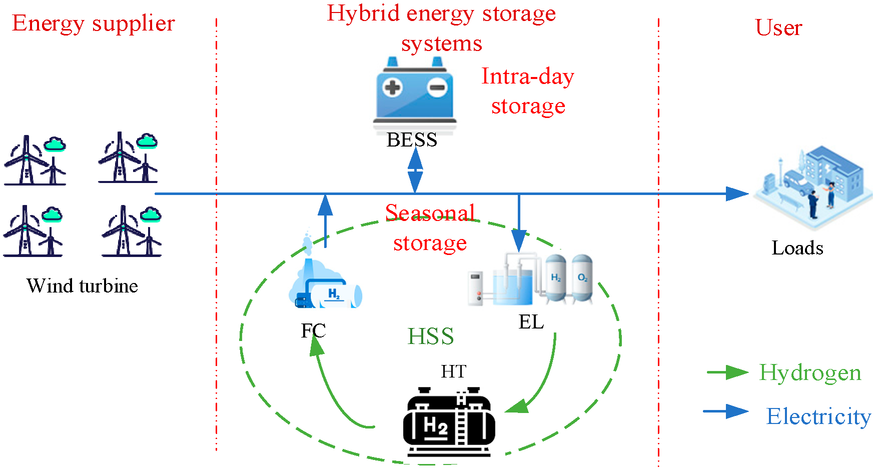
2. Operation Model of EH-HESS

2.1. Framework of EH-HESS

The community requires energy self-sufficiency due to its remote location which results in excessive establishment costs for connecting to the larger power grid. In this paper, an island energy system supplied only by wind energy is constructed to realize a low-carbon and sustainable operation, considering that the community is located in a renewable energy-rich area. The framework of the isolated energy system with EH-HESS is shown in Figure 1. The energy supplier section comprises multiple wind turbines. HESS includes a BESS and HSS. An EL, an HT, and an FC constitute HSS, in which EL converts electricity into hydrogen and deposits it into HT, while HT also supplies FC with hydrogen for combustion to generate electricity.
The EH-HESS is incorporated to handle intra-day and seasonal peak demands resulting from temporal and spatial imbalances in system supply and demand. BESS can achieve intra-day peak through charging and discharging. HSS is introduced here to absorb excess and release default energy along with BESS to alleviate the peak pressure. These measures make the system more flexible and efficient, allowing for energy transfer between seasons and improving overall system consumption levels.

2.2. Model of the EH-HESS

2.2.1. Hierarchical Time Discretization Model

The hierarchical time discretization model reference [27] used in this paper decomposes the time domain into multiple time scale intervals: hourly interval h H , daily interval d D , and seasonal interval s S .
The hourly interval is a characterization of the real-time variation of production and load demand among one-hour intervals n h = 1 of H = 24 hours during a typical day.
The daily interval is a characterization of the inter-day variation of production and demand. According to the periodicity of the supply and demand data, some days in each season are repeated n d times with a specific typical day. In this paper, the daily interval set D = 1 and n d = 91 , meaning each seasonal interval s contains n d identical days.
The seasonal interval is a characterization of the different season variations of production and demand. Several seasons of the year, similar to the day interval, are repeated at certain times n s . We set S = 4 and n s = 1 , meaning each season of the year operates with different situations.
Overall, based on the periodic nature of the data, using the time-stratified discretization method, the total periodic time interval of the system, H × D × S = 96 , significantly simplifies the model complexity compared to a continuous hourly interval of 8760 intervals, resulting in a total periodic time interval of the system. This method is applied to the ESS model, and, since ESS is continuously dynamic, each ESS link between and within different timescales is subject to constraints.

2.2.2. Model of Intra-Day Storage

BESS is always associated with energy curtailment in the intra-day peak with the BESS efficiency not being one. The S O C s , d , h BESS is presented in this paper to better illustrate the remaining power of BESS. The expression for calculating BESS the real-time capacity is shown as follows:
S s , d , h BESS = S s , d 1 , H BESS + h = 1 h ( η BESS _ cha P s , d , h BESS _ cha P s , d , h BESS _ dis η BESS _ dis ) s S , d D , h H
S O C s , d , h BESS = S s , d , h BESS S max BESS
where s , d , h are denote at moment h of a typical day h in season s ; S s , d , h BESS are the capacities at moments s , d , h ; S O C s , d , h B E S S express the states of charge of BESS at the moments s , d , h ; P s , d , h BESS _ cha and P s , d , h BESS _ dis are indicate the charging and discharging power of BESS, respectively; η BESS _ cha and η BESS _ dis are the BESS efficiency factors of charging and discharging; S max BESS is the storage capacity of BESS.
Current scheduling for intra-day peak of power systems usually requires ESS for 4~6 h of continuous charging and discharging [28]. This paper sets BESS’s continuous charging and discharging time to 6 h. The constraints are as follows:
0 P s , d , h BESS _ cha ξ s , d , h BESS _ cha S max BESS / 6 0 P s , d , h BESS _ dis ξ s , d , h BESS _ dis S max BESS / 6
ξ s , d , h BESS _ cha + ξ s , d , h BESS _ dis 1
0 S O C s , d , h BESS 1
S s , d , H BESS = S s , d 1 , H BESS
where ξ s , d , h BESS _ cha and ξ s , d , h BESS _ dis denote the variables of the charging and discharging state of the battery, which are binary variables. Equation (3) constrains the maximum charging and discharging power of BESS. Equation (4) restricts the BESS so that it cannot be charged and discharged at the same time. Equation (5) ensures the reasonable limits of the BESS state. Since BESS cannot interact with energy across days, Equation (6) limits the beginning and end states to be consistent within a typical day to ensure sustainable BESS operation.

2.2.3. Model of Seasonal Hydrogen Storage System

The HSS as seasonal energy storage focused on achieving inter-day transfers of energy considering the low self-loss efficiency of HT. Meanwhile, this paper unifies the use of power to characterize hydrogen and electrical energy for better calculations due to the inconsistency of the units of hydrogen and electrical energy [29]. The mathematical models of HSS are expressed below:
  • Electrolyze
EL is the equipment for hydrogen production in HSS by electrolysis of water. The conversion rate remains constant for simplification [30]. The energy conversion process can be shown as follows (7):
ν ˙ s , d , h el = η el P s , d , h el
where P s , d , h el indicates the power consumption of EL; ν ˙ s , d , h el and η el denote the hydrogen production rate (MW/h) and the hydrogen production efficiency, respectively.
  • Fuel Cell
Burning hydrogen released from HT can generate large amounts of electricity in FC:
v s , d , h fc = P s , d , h fc η fc
where P s , d , h fc denotes the power generated by FC; ν ˙ s , d , h fc and η fc denote the hydrogen consumption rate (MW/h) and efficiency, respectively.
  • Hydrogen Tank
The HT is mainly responsible for storing hydrogen, storing the hydrogen produced by the EL, or supplying hydrogen to the FC. This paper disregards the energy self-curtailment of HSS as its energy curtailment rate is negligible compared to BESS. Similar to a BESS, the S O C s , d , h HSS is set to the more intuitive determination of ESS status to facilitate scheduling [31]. The HT model in this paper is as follows:
S s , d , h HSS = S s , d 1 , H HSS + h = 1 H ( η EL P s , d , h EL P s , d , h FC η FC ) ; s S , d D , h H
I d s y HSS = S s , d , H HSS S s , d , 1 HSS ; s S , d D I s y HSS = d D n d S s , d , H HSS ; s S I y HSS = s S n s S s , D , H HSS
S O C s , d , h HSS = S s , d , h HSS S max HSS
where S O C s , d , h HSS are the storage states of HSS; S max HSS is the capacity of HT. Equation (9) describes the intra-day ESS energy variation in HT. Equation (10) represents the energy variation in HT across days and seasons. Equation (11) calculates the state of charge of HT.
HSS for seasonal dispatch requires the arrangement of unit maintenance by month combined with the future development of ESS technology; this paper sets the continuous charging and discharging time of HSS to 720 h [28]. The constraints are as follows:
0 v s , d , h EL ξ s , d , h EL S max HSS / 720 0 v s , d , h FC ξ s , d , h FC S max HSS / 720
ξ s , d , h EL + ξ s , d , h FC 1
0 S O C s , d , h HSS 1
I y HSS = 0
where ξ s , d , h el and ξ s , d , h fc represent the EL and FC working state variables, which are binary variables. Equation (12) represents the upper and lower limits of EL and FC power constraints. Equation (13) restricts the HSS from being charged and discharged at the same time. Equation (14) restricts the upper and lower limits of the HSS charge state. Because the HSS is seasonal energy storage, this paper, in Equation (15), sets the ESS state of HSS to be consistent from beginning to end throughout the year.

3. The Energy Operation Strategy of EH-HESS

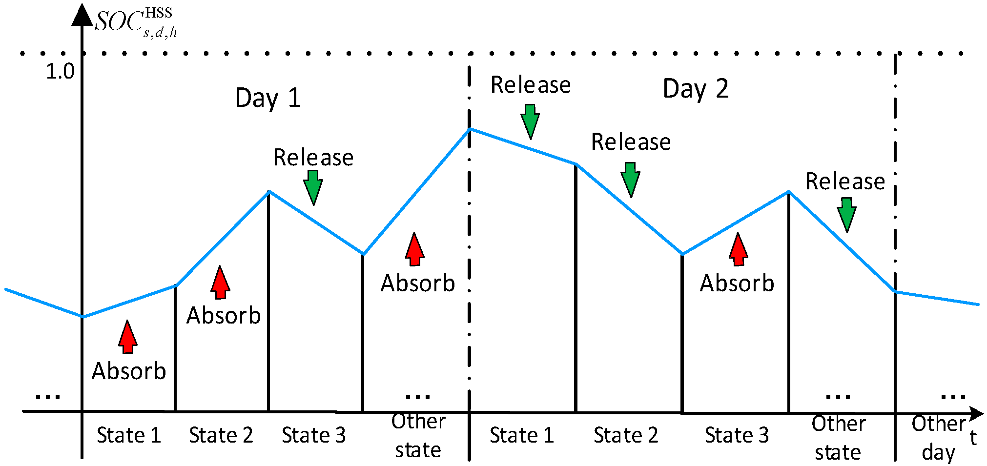
3.1. HSS Optimal State Transition Interval Model

The HSS as a seasonal ESS require year-round optimal scheduling with extremely high model complexity. However, the HSS has fewer operating times and changes of operating state in each season due to the predominant response to seasonal peaking [29], as shown in Figure 2. Considering the above, this paper designs an optimal state transition interval model for HSS, which ensures the maximum characterization of the real working situation while reducing the model complexity as much as possible.
HSS is limited in state transition m HSS , whereas RESs uncertainty leads to various typical daily operating state intervals. To ensure that HSS maximizes the absorption or supply of energy in the state interval, an optimal state transition interval model for HSS, considering the transition limits with maximized energy transfer, is proposed. The objective is to maximize the net load energy T in different intervals in the following (16):
max T = m = 1 m HSS T m
The typical day is separated into some intervals according to m HSS , and the sum of the system energy of each interval T m is calculated separately as follows:
T m = h = i m i m + 1 ( P s , d , h wind P s , d , h laod ) , i m [ 0 , 24 ]
where i m is the HSS transition partition node of m th, which is at time i m of a typical day. (17) is taken as an absolute value to avoid net power cancellation.

3.2. Interactive Energy Operation Strategies

The traditional energy operation strategy is shown in Figure 3a, where the HSS is set to work when the BESS cannot be utilized, as HSS is used to cope with seasonal demand. BESS’s power and capacity constraints are considered in the traditional energy operation strategy, which can effectively avoid over-charge or discharge [29]. However, its disadvantages are also more obvious:
(1)
The complementary mechanism of traditional strategy is simple superposition, which requires high ESS configuration requirements. The deep coupling of intraday and seasonal peak demands is laborious to clarify, making it difficult to actualize the effective configuration of HESS.
(2)
In the case of fixed ESS allocation, the complementary charge state has to be adjusted in real-time owing to the high fluctuation of RES to retain maximum adjustability.
(3)
Seasonal and intra-day peak demands are mixed in the net load demand, making it hard for a single ESS to fulfill peak demand at a certain moment.
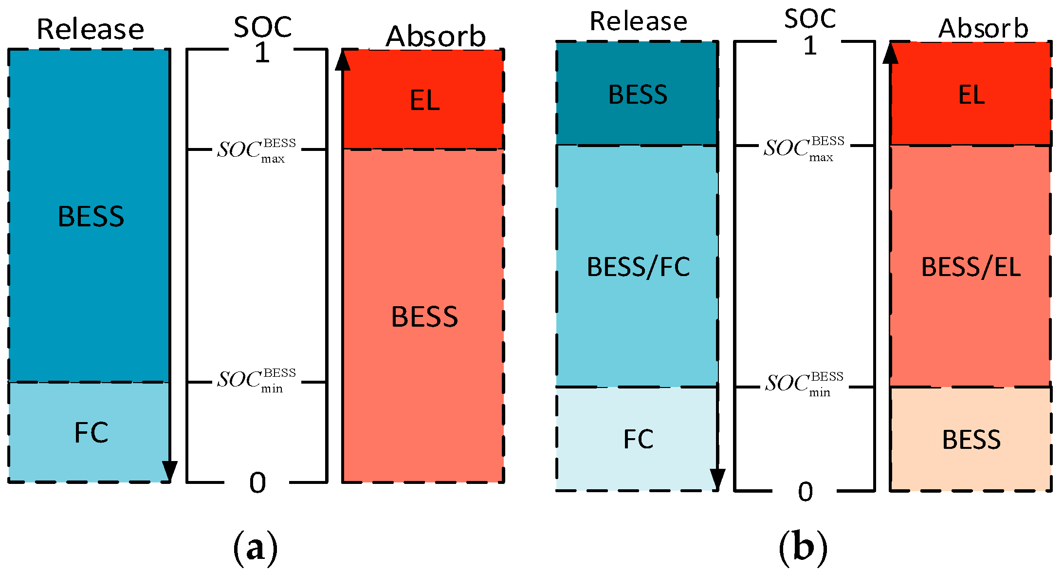
Figure 3. SOC regional division. (a) Traditional strategy; (b) proposed strategy.
Sustainability 16 07010 g003
This paper proposes a novel energy operation strategy so as to remedy the deficiency of the traditional energy operation strategy, as shown in Figure 3b. The specific novel energy operation strategy is outlined below:
(1)
S O C s , d , h BESS ( S O C min BESS , S O C max BESS ) : HSS and BESS working together. All ESSs can both supply or absorb energy at the same time, or HSS can charge to BESS or absorb BESS released. Due to the different energy conversion efficiencies of different ESSs, in order to improve the energy utilization of the system and reduce the energy loss and cost loss, the article optimizes the allocation of energy with the goal of minimizing the operating cost, as described in Section 4;
(2)
S O C s , d , h BESS ( 0 , S O C min BESS ) : If a system requires ESS to absorb energy, BESS works, and, conversely, HSS works;
(3)
S O C s , d , h BESS ( S O C max BESS , 1 ) : If a system requires ESS to deliver energy, BESS works, and, conversely, HSS works.
Compared to the traditional energy operation strategy [29] and other optimization algorithms [23], the novel strategy has the following advantages:
(1)
The novel strategy takes into account the energy interactions between the ESS and the existence of a zone in which the two ESSs work together. It expands the operating range of HSS to increase the utilization of HSS. Moreover, it can reduce the high requirement for energy storage configuration avoiding the inability to meet the regulation demand due to the irrational energy storage configuration under the fixed zoning.
(2)
The novel strategy retains the alone operation state to avoid overcharge/discharge of BESS, while rapidly returning to the desired operation interval.
(3)
The energy interaction intervals provide a buffer region. Compared to other literature which characterizes uncertainty through real-time scheduling [32] and robust optimization [33], to derive an optimal strategy, this article proposes a solution to uncertainty, namely, a model that sets up buffer intervals to cope with uncertainty, which can be better applied in practice. The two ESSs can work together in this interval with a regulation capability equal to the sum of the maximum charging and discharging power to improve the ability to cope with uncertainty.

4. Optimization and Solution of EH-HESS Operation Model

4.1. Objective Function

The optimal dispatch of EH-HESS contributes to the system’s economic objectives, which involve minimizing operating costs while considering wind abandonment and power curtailment penalties. The objective function of system optimal dispatch is shown in (18), with the minimum operating cost S as the target, which includes operating cost C work (19) and penalty cost C pns (23).
min S = C work + C pns
The operating cost is mainly composed of three parts: BESS operating cost C e , EL operating cost C el , FC operating cost C fc , and HT operating cost C ht in (19). The operating cost is described by the cost of energy lost and degradation during the operation of the ESS. To simplify the model, the BESS, FC, and EL are assumed to have a certain total life cycle power, and the degradation cost is mainly related to charge/discharge power. The degradation cost of HT is related to service life m.
C work = C e + C el + C fc + C ht
C e = n h n d n s s = 1 S d = 1 D h = 1 H ( χ e + θ e ) ( P s , d , h e _ cha + P s , d , h e _ dis ) C K = n h n d n s s = 1 S d = 1 D h = 1 H χ K + θ K P s , d , h K , K = el , fc C ht = C ht ac m
where C e , C el , and C fc are the operating costs of BESS, EL, and FC, respectively; χ e , χ el , and χ fc are the operating unit prices of BESS, EL, and FC, respectively, which are related to the amount of energy lost in the process of operation. Equations (21) and (22) detailed describes each degradation cost θ e and θ K [34].
θ e = C e ac S BESS max · N cycle nom
θ K = C K ac H K nom · P K max
The depreciation cost of ESS is tied to the investment cost and lifetime, where C e ac , C el ac , and C fc ac mean are the acquisition costs of BESS, EL, and FC, respectively; S BESS max , N cycle nom is the capacity and maximum number of operating cycles of BESS, and H el nom and H fc nom equal the maximum operating hours of EL and FC, respectively [34].
The penalty cost of the system consists of two components: the wind abandonment penalty C lose and the power curtailment penalty C reach .
C pns = C lose + C reach
C lose = n h n d n s s = 1 S d = 1 D h = 1 H χ l _ wind P s , d , h lose C reach = n h n d n s s = 1 S d = 1 D h = 1 H χ l _ e P s , t reach
where χ l _ wind and χ l _ e are the unit prices of wind abandonment and power curtailment penalties, respectively. P s , d , h lose and P s , d , h reach are the wind power abandoned and power curtailment. Equation (24) describes each penalty cost.

4.2. Constraint

To ensure that the system can operate sustainably and effectively, this paper introduces several constraints for the optimal operation of the BESS, ranging from (1) to (6), while the HSS is subjected to constraints from (7) to (15). In addition, the EH-HESS must abide by power balance constraints in real-time to ensure that the system’s operation remains reasonable.
P s , d , h wind + P s , d , h fc + P s , d , h e _ dis + P s , d , h reach = P s , d , h load P s , d , h load _ l + P s , d , h el + P s , d , h e _ cha + P s , d , h lose
where P s , d , h load _ l denotes total electrical load curtailment.

4.3. Linearization

The EH-HESS operation strategy includes the scheduling of ESSs under various scenarios and thus involves several if-conditional statements, which in turn have to be linearized for a more optimal solution. Linear constraints can be applied using logical variables for different situations.
S O C s , d , h e S O C max e M a S O C s , d , h e S O C max e M ( 1 a )
S O C s , d , h e S O C min e M b S O C s , d , h e S O C min e M ( 1 b )
where a and b are all Boolean variables; M is an infinite number. Equations (26) and (27) describe S O C s , d , h e ( S O C max e , 1 ) and S O C s , d , h e ( 0 , S O C min e ) .
For the specific case of ESS operation, it is the intersection of the above conditions.
e b e ξ s , d , h EL e b + ξ s , d , h EL 1
where e are binary variables. Equation (28) describes EL work conditions. Other cases are similar to (28).
This paper establishes the linear programming model of EH-HESS with (18)–(24) as the objective function and (1)–(15) and (25)–(28) as the constraints and invokes the CPLEX commercial solver based on the MATLAB platform to solve the problem.

4.4. Evaluation Indicators

This paper adopts the load loss rate γ SLD and energy excess rate γ EER to characterize the islanded system reliability in order to facilitate the analysis of microgrid wind and solar power abandonment and load loss:
γ SLD = P s , d , h lose P s , d , h load γ EER = P s , d , h reach P s , d , h wind

5. Case Study

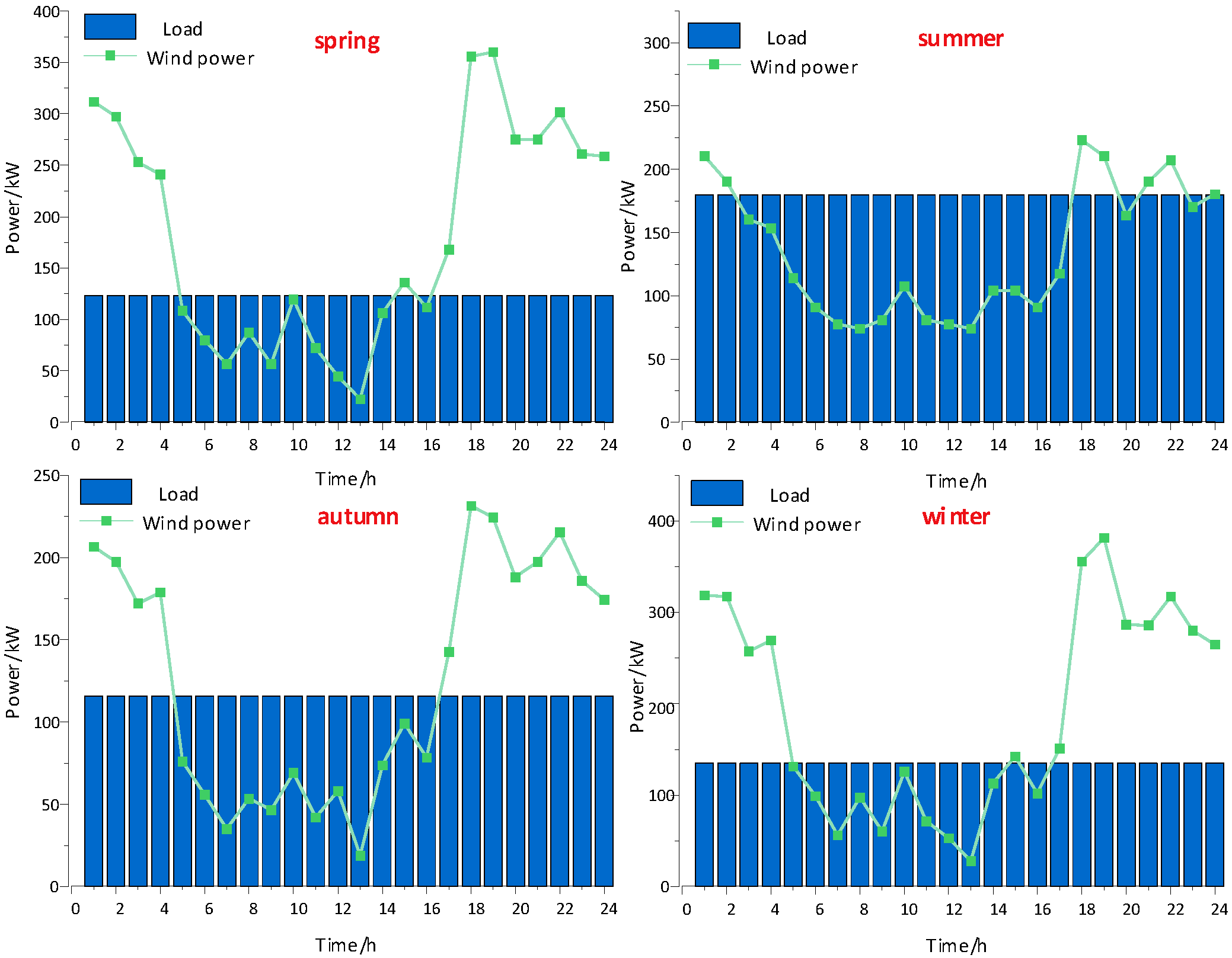
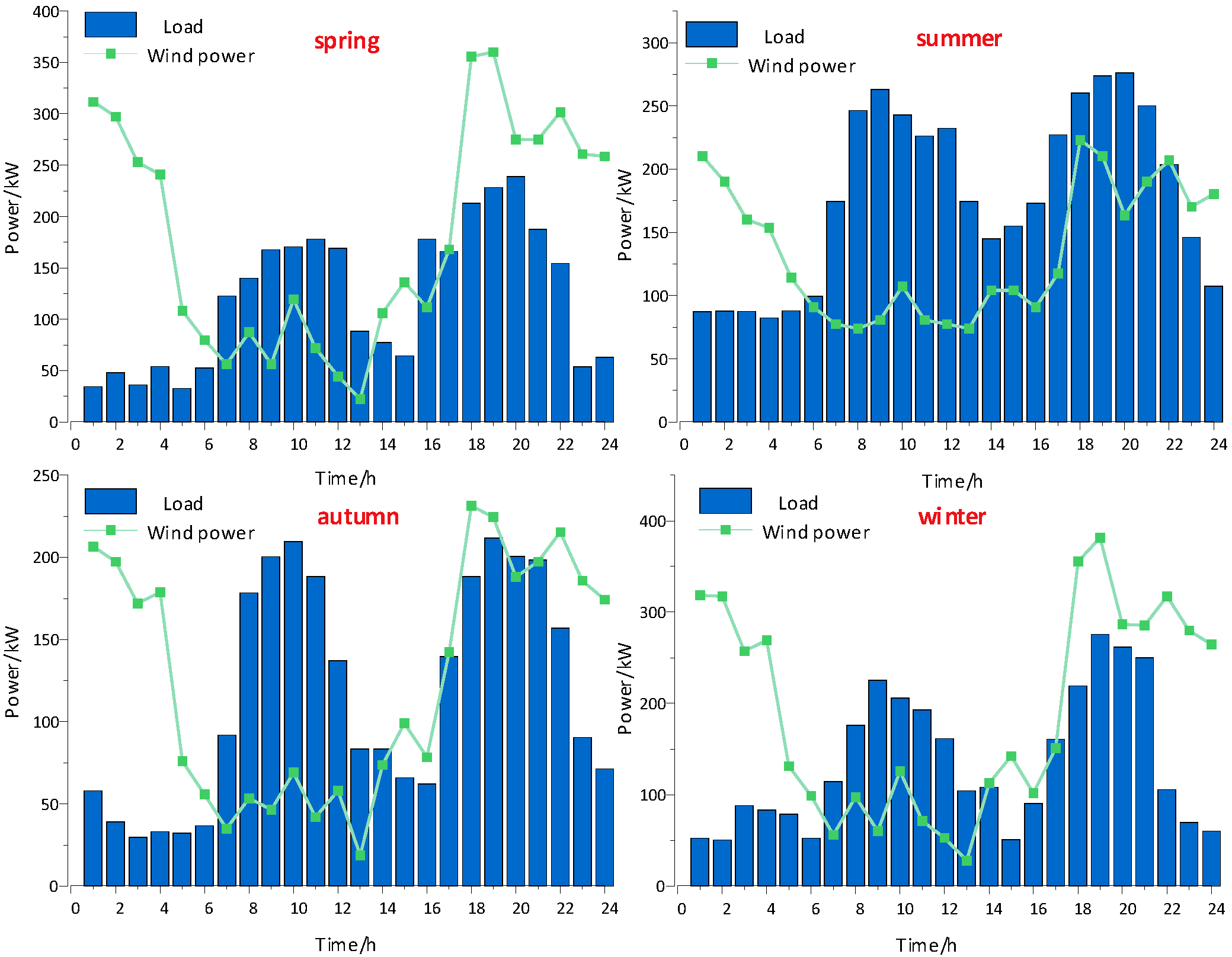
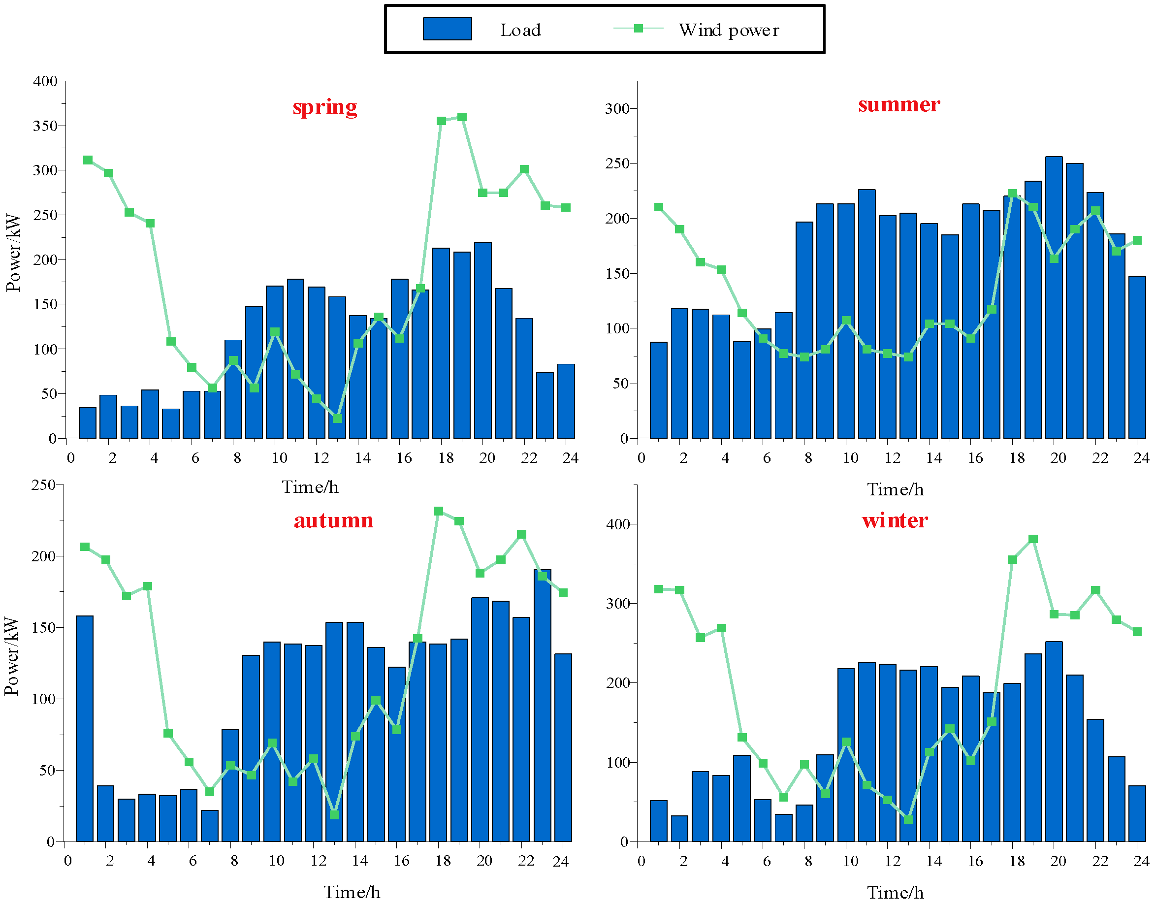
5.1. Initial Parameters and Data

In this paper, the EH-HESS is analyzed within the context of a typical wind–hydrogen coupled system based on previous work [24,30]. This study uses real-world wind data from an isolated energy system located in northwest China to describe renewable energy. To simplify the calculation, wind speed data are divided into four typical days using K-means clustering where winter and spring are windy, summer is low, and autumn is less windy. The output power of wind can be calculated with wind speed and radiation intensity. The load data are also reduced to 4 days to correspond to typical days of wind power output. Among them, the demand for load is high in summer, less in autumn, and low in spring and summer. Wind power and load data are shown in Figure 4. Furthermore, Table 3 displays the capacity, output power, operation cost, and penalty cost associated with EH-HESS devices.
Figure 4 shows a large energy curtailment in the summer and a large energy surplus in the spring and winter, which requires ESSs able to deliver seasonal peaking through inter-day energy transfer. We set up three cases to verify the economy and feasibility of the proposed model and strategy. The ESS parameters configured for each case system are shown in Table 4.
  • Case 1: A single BESS model without HSS is presented.
  • Case 2: An EH-HESS model with a traditional operation strategy is examined.
  • Case 3: An EH-HESS model with a proposed operation strategy is evaluated.

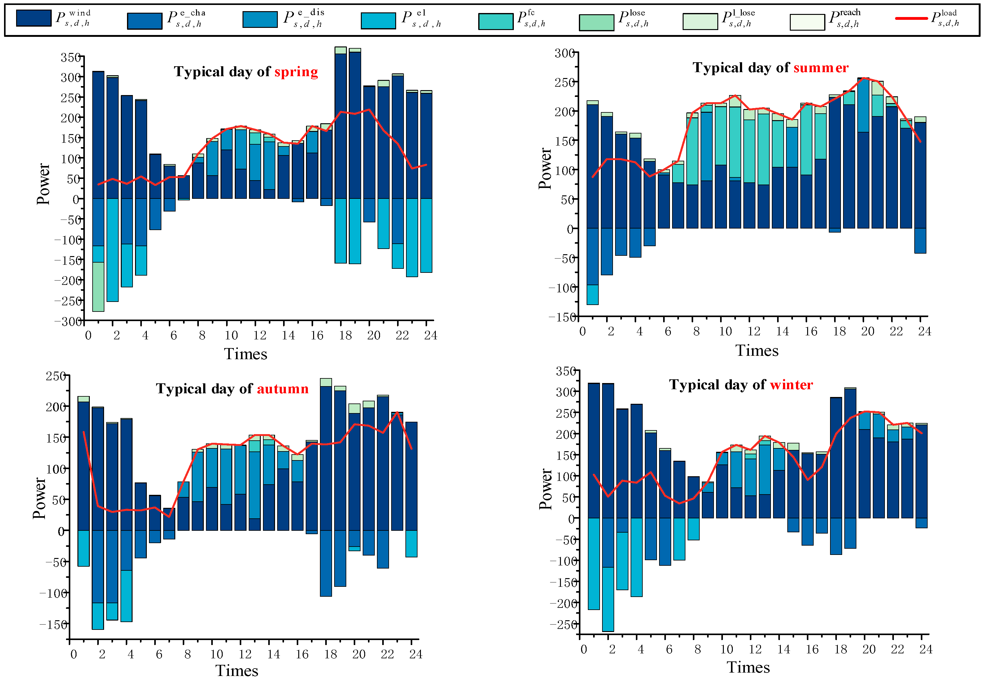
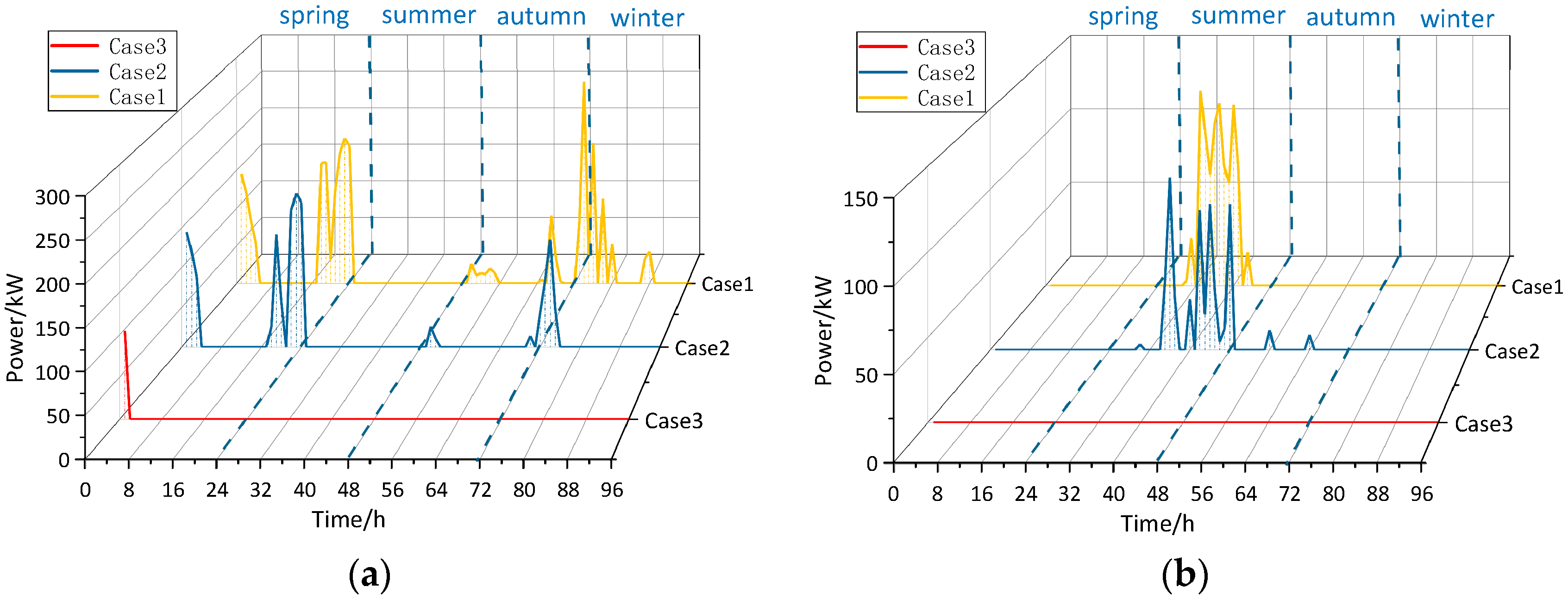
5.2. Benefit of EH-HESS Modeling

The optimized operating costs under different ESS allocations are summarized in Table 5, with Case 1 having the highest cost. Case 1 is not equipped with HSS, which is unable to transfer energy between days, resulting in wind curtailment and load curtailment. Case 2 and Case 3 equipped with HSS can reduce the load loss rate and energy excess rate by 30.9% and 85.9%, respectively, compared to Case 1. In this case, the allocation of the HSS increases the investment cost, but the HSS still significantly decreases the penalty cost thanks to the capacity to transfer energy between days, resulting in a still lower total cost of the EH-HESS. The operating cost of HSS is significantly increased and the penalty cost is further reduced, indicating that the new operating strategy strongly increases the utilization of HSS and improves the energy utilization of the system.
Further analysis of Case 3 to demonstrate the way of coping with the seasonal peak demand due to the lowest economic cost is shown in Figure 5. The overall system energy in spring and winter is redundant, resulting in an EL working to absorb the excess energy. For example, in spring, from 0:00–8:00, BESS and HSS together absorb energy. BESS in 8:00–16:00 releases the stored energy to meet the intra-day peak shaving. The wind after 16:00 is much stronger than the load, resulting in HSS storing the excess energy. A large energy curtailment exists in summer, with almost FC burning hydrogen to provide electricity. The load at 0:00–6:00 is small and BESS stores energy. After 6:00, BESS releases energy to make up for the shortfall, but it is far from enough. HSS will further release energy stored in spring and winter to make up for shortfalls enabling seasonal peak shaving. In the autumn, supply and demand are basically balanced, and HSS is barely working. HSS stores the surplus energy in the spring and winter to release it in the summer to compensate for the curtailment of energy and improve energy utilization.
HSS transfers energy unavailable for utilization in the spring and winter to be consumed in summer, and BESS enables peak shaving and valley filling during the day. The effective combination of EH-HESS improves energy utilization.

5.3. Benefits of Energy Operation Strategies

5.3.1. Wind Abandonment and Curtailment of Load

The amount of abandoned wind and power curtailment for different cases is shown in Figure 6. Case 3 is much smaller than the other cases by comparing the three cases, and Case 2 is lower than Case 1. This shows that the energy operation strategy proposed in the article effectively improves the consumption level of the system.
The combined response of BESS and HSS to peak demand greatly relieves the pressure of peak shaving from a single storage, e.g., 0:00–6:00, during spring in Figure 5. The proposed operation strategy breaks the maximum power constraint of the single ESS, allowing the EH-HESS to meet most of the peak demand, resulting in a sudden drop in wind abandonment and a curtailment of the load on the system. In addition, the reduction of the phenomenon indicates that the energy in the abundance period is efficiently stored in the HT so that the energy can be transferred efficiently to cover the shortfall in the valley period, further proving the superiority of the proposed strategy. The new operation strategy can release more energy from HSS in summer, e.g., 8:00–16:00 of summer in Figure 5, owing to the consumption of abandoned energy, leading to a significant reduction in curtailment. The new energy management strategy focuses on effectively harvesting abandoned wind energy and releasing more energy in the summer, hence greatly reducing the penalized cost of the system. The new operation strategy focuses on effectively harvesting abandoned energy and releasing more energy in the summer, hence greatly reducing the penalized cost of the system.

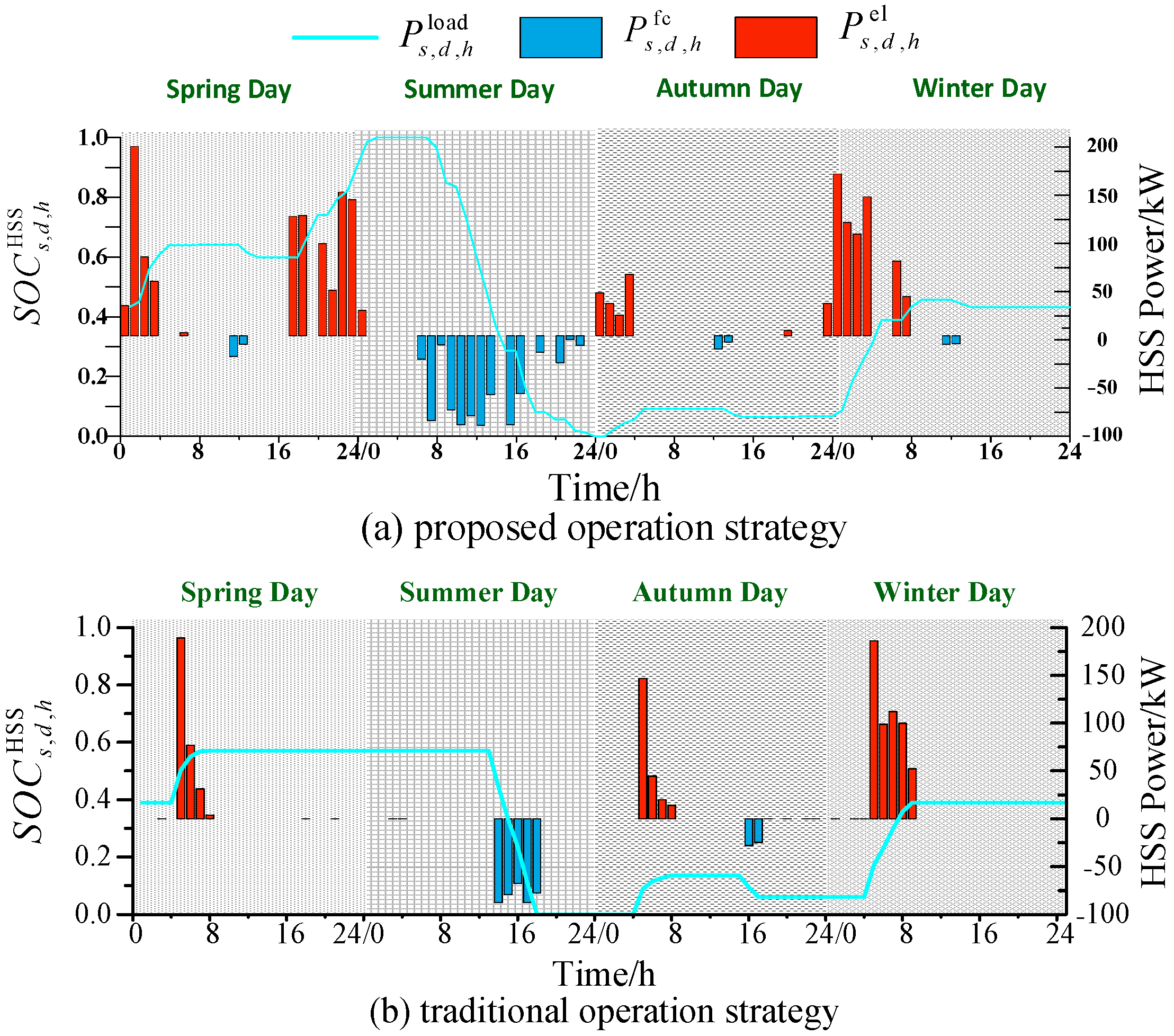
5.3.2. Energy Storage Utilization

The operation of HSS under the proposed operation strategies can be shown in Figure 7. The new operation strategy can significantly improve the utilization of HSS, with 42 times HSS operations and 43.7% of the total running time, which is 2.1 times more than Case 2. Because of the narrow operating interval of the traditional operation strategy, HSS can be seen to be inactive at the beginning of a typical day until BESS no longer consumes or makes up energy, especially in the 16:00–23:00 and 31:00–48:00 periods. As a consequence of the extended working interval, HSS in Case 3 is in charge for 23 h compared to in Case 2, with an increase of 76.9%. Similarly, the discharge period in summer is increased by 140% compared to in Case 2. At the same time, it can be seen that EL and FC work hours are closely related to the system supply and demand, especially in summer 31:00–48:00. Although there can be three conversions in a day, the desirable result is that FC can work all the time after 31:00; so, a reasonable state division is more conducive to the improvement of the system’s consumption level.
It can be seen that the HSS is stored to full capacity in the spring and released in the summer, with the charge state dropping to 0. The charge state curve of HSS can intuitively reflect the fact that, under the proposed operation strategy, HSS is fully utilized and fully discharged in the same ESS configuration.

5.4. Sensitivity Analysis

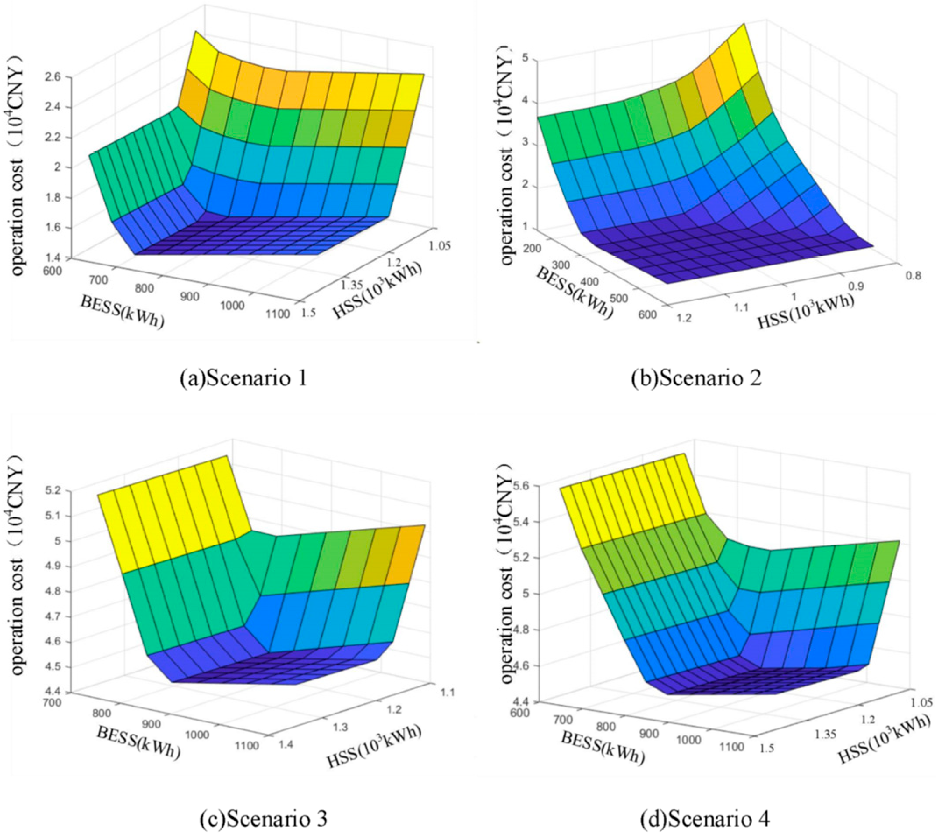
5.4.1. EH-HESS Allocation

Seasonal complementary characteristics of diverse regions can lead to varying demand for EH-HESS. The optimal EH-HESS allocation to minimize the operating cost is explored for diverse seasonal ratios [23]: Scenario 1: Same proportion in all seasons; Scenario 2: Double the proportion in winter as in summer and the same proportion in spring and fall; Scenario 3: Double the proportion in summer as in winter, and the same proportion in spring and fall; Scenario 4: Double the proportion in summer and winter as in spring and fall.
The operating costs show a concave surface with a nadir that exists with increasing ESS capacity in Figure 8. As ESS capacity increases at a minor point, it rapidly reduces operating costs. However, the operational cost gradually increases as it continues to grow greater than the system peak demand, at which point the increase is related to the cost of ESS. In particular, the minimum operating costs for Scenarios 1 and 2 are similar, but the optimal EH-HESS allocation for Scenario 2 is smaller than for Scenario 1. Wind energy is more sufficient in Scenario 2, which is mostly utilized for intra-day and seasonal peak shaving to reduce wind abandonment, in view of the low efficiency of electricity–electricity conversion in HSS, which is undesirable. The optimal allocations for scenarios 3 and 4 are similar, with significantly higher operating costs than for scenarios 1 and 2. The reason is that the system’s peak demands are similar, and none of the scenarios can be catered for, although the seasonal proportions are diverse. Compared to Scenario 1, the HSS is similar to Scenario 1. Hence, the seasonal proportions change, but the seasonal demands are similar, resulting in similar optimal allocations of HSS.
The worse the seasonal complementary characteristics, the higher the operating costs. Exceptionally, when complementarity is poor but overall energy is rich, HSS undertakes part of the intra-day peak to avoid wind curtailment penalties due to high energy losses. Yet allocation with this scenario only will not be sufficient for all seasonal proportions to meet intra-day peak demand. Hence, the allocation of optimal inter-seasonal complementarities as a reference to effectively cope with multiple volatilities in the face of different seasonal ratios may be possible.

5.4.2. Limit on the Times of HSS State Transitions

The supply and demand relationship during the day will be varied under different load types. This paper explores the impact of the number of HSS state transition limits on system operating costs under different load types. Three load types are considered [34]: Load 1: Industrial load, no peak in Figure A1; Load 2: Residential load, single peak; Load 3: Commercial load, twin peaks in Figure A2. The load curves are generated based on the load characteristics assuming a constant total load in order to highlight the contrast between different types of loads.
The cost decreases with the loosening of the HSS state transition limit for various load types until the number of times is limited to three without decreasing. Conversion of net load changes will increase under the load type of bimodal peaks, whereas the energy in the conversion-frequent intervals is more skewed towards intraday peak demand, with negligible demand for HSS. Therefore, this part can be merged into the other state intervals. As can be seen from Table 6, the greater the load variation, the more the cost decreases as the number of restrictions increases. Each load type (Load 1, Load 2, Load 3) was reduced by 4.6%, 18.21%, and 45.98%, respectively, compared to the once-state limit. The seasonal peak demand tackled by HSS is more energy that cannot be dissipated by BESS; as such, the interval needs to be moderately widened. Accordingly, the increase in the number of HSS state transition limits can effectively improve the level of consumption in the face of different load types, especially to satisfy the more variable loads despite the fact that supply and demand change under different types of loads, seasonal peak demand is still mostly divided into three intervals, given that the limitation of three times for the number of energy conversions is deemed to be optimal.

6. Conclusions

In this paper, an EH-HESS based on new operation strategies was investigated in a remote isolated energy system to meet the urgent need for a stable energy supply. The following conclusions are obtained from the case study:
(1)
The EH-HESS can effectively cope with the intraday and seasonal peak demands. The EH-HESS greatly diminishes the load loss and curtailment associated with the complementary energy storage characteristics, reducing the load loss rate to 1.06% and the energy excess rate to 0%.
(2)
The new operation strategy increases the number of HSS working times by 2.1 times by increasing the interaction interval. It avoids the low utilization rate of HSS due to the irrational division of fixed zones. Additionally, the appearance of the interaction interval allows HESS to jointly respond to the high power demand.
(3)
As the ESS allocation increases, the operating cost decreases and increases later. The allocation of optimal seasonal complementary shall prevail as a reference in the face of different seasonal ratios. The increase in the number of state limits facilitates HSS higher utilization three times, decreasing the operating cost by 4.6% after it has no further effect. The three state limits are the most reasonable limits by comparing different load types. These results can assist investors in better decision-making.
There are some limitations that should be addressed in future research. The energy management strategy briefly considers the effect of uncertainty by increasing the energy interaction interval and scenario method. In the future, we will model the uncertainty of renewable energy sources and loads based on the model in this paper, and study energy management strategies that take uncertainty into account.

Author Contributions

Conceptualization, L.C., X.L. and C.Y.; methodology, C.Y. and X.L.; formal analysis, C.Y.; investigation, S.M.; writing—original draft preparation, C.Y.; writing—review and editing, L.C., X.L. and S.M.; funding acquisition, S.M. All authors have read and agreed to the published version of the manuscript.

Funding

This research was funded by the Joint Funds of the National Natural Science Foundation of China, grant number U22A20224, and the National Natural Science Foundation of China (Youth Fund Program), grant number 52307108.

Institutional Review Board Statement

Not applicable.

Informed Consent Statement

Not applicable.

Data Availability Statement

Data are contained within the article.

Conflicts of Interest

The authors declare no conflicts of interest.

Appendix A

Figure A1. Industrial load and wind power.
Sustainability 16 07010 g0a1
Figure A2. Commercial load and wind power.
Sustainability 16 07010 g0a2

References

  1. Zhou, J.; Weng, Z.; Song, X. Capacity Configuration Method of Islanded Microgrid with Photovoltaic and Energy Storage System Considering Reliability and Economy. Autom. Electr. Power Syst. 2021, 45, 166–174. [Google Scholar]
  2. Zhou, X.; Chen, S.; Lu, Z.; Huang, Y.; Ma, S.; Zhao, Q. Technology Features of the New Generation Power System in China. Proc. CSEE 2018, 38, 1893–1904. [Google Scholar]
  3. Ren, D.; Hou, J.; Xiao, J.; Jin, Y.; Jin, C.; Hui, D. Exploration of Key Technologies for Energy Storage in the Cleansing Transformation of Energy and Power. High Volt. Eng. 2021, 47, 2751–2759. [Google Scholar] [CrossRef]
  4. Jiang, P.; Zhang, H.; Li, M.; Zhang, Y.; Gong, X.; He, D.; Liu, L. Research on the Structural Optimization of the Clean Energy Industry in the Context of Dual Carbon Strategy—A Case Study of Sichuan Province, China. Sustainability 2023, 15, 2993. [Google Scholar] [CrossRef]
  5. Twitchell, J.; DeSomber, K.; Bhatnagar, D. Defining Long Duration Energy Storage. J. Energy Storage 2023, 60, 105787. [Google Scholar] [CrossRef]
  6. Jiang, H.; Du, E.; Zhu, G.; Huang, J.; Qian, M.; Zhang, N. Review and Prospect of Seasonal Energy Storage for Power System with High Proportion of Renewable Energy. Autom. Electr. Power Syst. 2020, 44, 194–207. [Google Scholar]
  7. Khani, H.; Farag, H.E.Z. Joint Arbitrage and Operating Reserve Scheduling of Energy Storage through Optimal Adaptive Allocation of the State of Charge. IEEE Trans. Sustain. Energy 2018, 10, 1705–1717. [Google Scholar] [CrossRef]
  8. Sun, C.; Chen, L.; Qiu, X.; Zheng, T.; Mei, S. A Generation-Side Shared Energy Storage Planning Model Based on Cooperative Game. J. Global Energy Interconnect. 2019, 2, 360–366. [Google Scholar]
  9. Yang, Y.; Qin, C.; Zeng, Y.; Wang, C. Optimal Coordinated Bidding Strategy of Wind and Solar System with Energy Storage in Day-ahead Market. J. Mod. Power Syst. Clean Energy 2022, 10, 192–203. [Google Scholar] [CrossRef]
  10. Hunt, J.D.; Falchetta, G.; Parkinson, S.; Vinca, A.; Zakeri, B.; Byers, E.; Jurasz, J.; Quaranta, E.; Grenier, E.; Junior, A.O.P.; et al. Hydropower and seasonal pumped hydropower storage in the Indus basin:pros and cons. J. Energy Storage 2021, 41, 102916. [Google Scholar] [CrossRef]
  11. Hunt, J.D.; Zakeri, B.; Nascimento, A.; Gazoli, J.R.; Bindemann, F.T.; Wada, Y.; Riahi, K. Compressed Air Seesaw Energy Storage: A Solution for Long-Term Electricity Storage. J. Energy Storage 2023, 60, 106638. [Google Scholar] [CrossRef]
  12. Abomazid, A.M.; El-Taweel, N.A.; Farag, H.E.Z. Optimal Energy Management of Hydrogen Energy Facility Using Integrated Battery Energy Storage and Solar Photovoltaic Systems. IEEE Trans. Sustain. Energy 2022, 13, 1457–1468. [Google Scholar] [CrossRef]
  13. Shu, X.; Kumar, R.; Saha, R.K.; Dev, N.; Stević, Ž.; Sharma, S.; Rafighi, M. Sustainability Assessment of Energy Storage Technologies Based on Commercialization Viability: MCDM Model. Sustainability 2023, 15, 4707. [Google Scholar] [CrossRef]
  14. Kummer, K.; Imre, A.R. Seasonal and Multi-Seasonal Energy Storage by Power-to-Methane Technology. Energies 2021, 14, 3265. [Google Scholar] [CrossRef]
  15. Yuan, Z.; Wang, W.; Li, J. Carbon dioxide recycling in hydrogen-based energy systems using power-to-gas facility and stochastic multi-objective optimization. J. Clean. Prod. 2023, 387, 13582. [Google Scholar] [CrossRef]
  16. Zhou, Y. Transition towards carbon-neutral districts based on storage techniques and spatiotemporal energy sharing with electrification and hydrogenation. Renew. Sustain. Energy Rev. 2022, 162, 112444. [Google Scholar] [CrossRef]
  17. Pelosi, D.; Baldinelli, A.; Cinti, G.; Ciupageanu, D.-A.; Ottaviano, A.; Santori, F.; Carere, F.; Barelli, L. Battery-hydrogen vs. flywheel-battery hybrid storage systems for renewable energy integration in mini-grid: A techno-economic comparison. J. Energy Storage 2023, 63, 106968. [Google Scholar] [CrossRef]
  18. Ji, M.; Zhang, W.; Xu, Y.; Liao, Q.; Klemeš, J.J.; Wang, B. Optimisation of multi-period renewable energy systems with hydrogen and battery energy storage: A P-graph approach. Energy Convers. Manag. 2023, 281, 116826. [Google Scholar] [CrossRef]
  19. Le, T.S.; Nguyen, T.N.; Bui, D.-K.; Ngo, T.D. Optimal sizing of renewable energy storage: A techno-economic analysis of hydrogen, battery and hybrid systems considering degradation and seasonal storage. Appl. Energy 2023, 336, 120817. [Google Scholar] [CrossRef]
  20. Li, Q.; Li, R.; Pu, Y.; Li, S.; Sun, C.; Chen, W. Coordinated control of electric-hydrogen hybrid energy storage for multi-microgrid with fuel cell/electrolyzer/PV/battery. J. Energy Storage 2021, 42, 103110. [Google Scholar] [CrossRef]
  21. Luo, L.; Han, Y.; Li, Q.; Chen, X.; Pu, Y.; Chen, W. Economic droop control strategy of a hybrid electric-hydrogen DC microgrid considering efficiency characteristics. Power Syst. Prot. Control 2022, 50, 69–80. [Google Scholar] [CrossRef]
  22. Wang, H.; Xie, Z.; Pu, L.; Ren, Z.; Zhang, Y.; Tan, Z. Energy management strategy of hybrid energy storage based on Pareto optimality. Appl. Energy 2022, 327, 120095. [Google Scholar] [CrossRef]
  23. Pan, G.; Gu, W.; Lu, Y.; Qiu, H.; Lu, S.; Yao, S. Optimal Planning for Electricity-Hydrogen Integrated Energy System Considering Power to Hydrogen and Heat and Seasonal Storage. IEEE Trans. Sustain. Energy 2020, 11, 2662–2676. [Google Scholar] [CrossRef]
  24. Xu, Y.C.; Liu, H.Q.; Sun, S.H.; Mi, L. The Bi-Level Mixed Integer Programming of Multi-Microgrid System Considering the Hybrid Energy Sharing Station. Proc. CSEE 2022, 59, 1–14. [Google Scholar]
  25. Li, R.R.; Li, Q.; Pu, Y.C.; Li, S.; Sun, C.; Chen, W.R. Optimal Configuration of an Electric-Hydrogen Hybrid Energy Storage Multi-Microgrid System Considering Power Interaction Constraints. Power Syst. Prot. Control 2022, 50, 53–64. [Google Scholar]
  26. Chen, M.; Shen, Z.; Wang, L.; Zhang, G. Intelligent Energy Scheduling in Renewable Integrated Microgrid with Bidirectional Electricity-to-Hydrogen Conversion. IEEE Trans. Netw. Sci. Eng. 2022, 9, 2212–2223. [Google Scholar] [CrossRef]
  27. Samsatli, S.; Samsatli, N.J. A general spatio-temporal model of energy systems with a detailed account of transport and storage. Comput. Chem. Eng. 2015, 80, 155–176. [Google Scholar] [CrossRef]
  28. Xiao, J.; Hou, J.; Du, E.; Jin, C.; Zhou, Y.; Kang, C. Quantitative Model and Case Study of Energy Storage Demand Supporting Clean Transition of Electric Power System. Autom. Electr. Power Syst. 2021, 45, 9–17. [Google Scholar]
  29. Xiong, Y.; Chen, L.; Zheng, T.; Si, Y.; Mei, S. Optimal Configuration of Hydrogen Energy Storage in Low-Carbon Park Integrated Energy System Considering Electricity-Heat-Gas Coupling Characteristics. Electr. Power Autom. Equip. 2021, 41, 31–38. [Google Scholar]
  30. Yuan, T.; Cao, J. Capacity Optimization Allocation of Wind Hydrogen Low-Carbon Energy System Considering Wind Power-Load Uncertainty. High Volt. Eng. 2022, 48, 2037–2044. [Google Scholar]
  31. Reuß, M.; Grube, T.; Robinius, M.; Preuster, P.; Wasserscheid, P.; Stolten, D. Seasonal Storage and Alternative Carriers: A Flexible Hydrogen Supply Chain Model. Appl. Energy 2017, 200, 290–302. [Google Scholar] [CrossRef]
  32. Liu, X.; Zu, L.; Li, X.; Wu, H.; Ha, R.; Wang, P. Day-Ahead and Intra-Day Economic Dispatch of Electricity Hydrogen Integrated Energy System with Virtual Energy Storage. IEEE Access 2023, 11, 104428–104440. [Google Scholar] [CrossRef]
  33. Jiang, Y.; Ren, Z.; Li, W. Committed Carbon Emission Operation Region for Integrated Energy Systems: Concepts and Analyses. IEEE Trans. Sustain. Energy 2023, 15, 1194–1209. [Google Scholar] [CrossRef]
  34. García-Triviño, P.; Fernández-Ramírez, L.M.; Gil-Mena, A.J.; Llorens-Iborra, F.; García-Vázquez, C.A.; Jurado, F. Optimized operation combining costs, efficiency and lifetime of a hybrid renewable energy system with energy storage by battery and hydrogen in grid-connected applications. Int. J. Hydrogen Energy 2016, 41, 23132–23144. [Google Scholar] [CrossRef]
Figure 1. The framework of the isolated energy system with EH-HESS.
Sustainability 16 07010 g001
Figure 2. HSS working state change.
Sustainability 16 07010 g002
Figure 4. Load and wind power of typical day.
Sustainability 16 07010 g004
Figure 5. Energy scheduling of EH-HESS.
Sustainability 16 07010 g005
Figure 6. Wind abandonment and curtailment of load. (a) Wind power abandonment of EH-HESS. (b) Power curtailment of EH-HESS.
Sustainability 16 07010 g006
Figure 7. HSS energy scheduling.
Sustainability 16 07010 g007
Figure 8. Operating costs of different scenarios.
Sustainability 16 07010 g008
Table 3. Device equipment parameters.
ParametersValueParametersValue
η el /%0.6 χ fc /(CNY/kW)14.1
η fc /%0.7 χ l _ e /(CNY/kW)100
η e /%0.9 χ l _ wind /(CNY/kW)47
χ el /(CNY/kW)18.8 χ e /(CNY/kW)4.7
m (year)20 N cycle nom (time)250
H el nom (hour)131,400 H fc nom (hour)52,560
Table 4. Equipment configuration of the system.
CaseBESSHSS
S max e (kW · h) P max e _ out (kW) P max e _ in (kW) S max hs (kW · h) P max el
(kW)
P max fc
(kW)
1800133133---
2126,000292123
3126,000292123
Table 5. Operating costs of EH-HESS.
Cost
(CNY)
C e C el C fc C ht C lose C reach γ SLD γ EER S
Case 17035---10,56684,63016.57%6.89%102,231
Case 2722220901054507635653,3943.93%4.34%70,624
Case 356645218235650767301.06%0%14,418
Table 6. Optimal operating costs with different limitation times.
Load
Type
m HSS S (CNY) C ESS (CNY) C lose (CNY) C reach (CNY)
Load 1113,77911,50222770
213,71811,64520730
313,14413,0061380
413,14413,0061380
Load 2116,99313,09110062896
215,08513,2217681096
314,41813,7456730
414,41813,7456730
Load 3130,36714,222225113,930
223,47914,71513327432
316,40315,170513720
416,40315,170513720
Disclaimer/Publisher’s Note: The statements, opinions and data contained in all publications are solely those of the individual author(s) and contributor(s) and not of MDPI and/or the editor(s). MDPI and/or the editor(s) disclaim responsibility for any injury to people or property resulting from any ideas, methods, instructions or products referred to in the content.

