Article

Research on Intelligent Prefabricated Reinforced Concrete Staircase Lifting Point Setting Method Considering Multidimensional Spatial Constraint Characteristics

1
Key Laboratory of New Technology for Construction of Cities in Mountain Area, Chongqing University, Chongqing 400045, China
2
School of Civil Engineering, Chongqing University, Chongqing 400045, China
3
Chongqing Railway Group, Chongqing 400045, China
4
Puyang Longyuan Electric Power Design Co., Puyang 457000, China
*
Author to whom correspondence should be addressed.
Sustainability 2024, 16(14), 5843; https://doi.org/10.3390/su16145843
Submission received: 31 May 2024 / Revised: 25 June 2024 / Accepted: 5 July 2024 / Published: 9 July 2024

Abstract

:
Prefabricated reinforced concrete staircases (PC staircases) are prefabricated components that are widely used in prefabricated buildings and are used in large quantities. During the production and construction of a PC staircase, the lifting point setting directly affects the construction safety, construction efficiency, and construction quality. In this paper, we analyze the quality problems and safety risks in the design, production, and construction of PC staircases under the constraints of multidimensional spatial characteristics, clarify the key technical difficulties of prefabricated staircase lifting under the multidimensional spatial and temporal constraints, and analyze the factors that should be considered in the setting of lifting points. In this paper, a prefabricated staircase lifting point setting database is established and a thin-plate spline interpolation algorithm is introduced to expand it. Based on the support vector machine algorithm, the process of optimization is carried out for the kernel function scale parameter and penalty factor, and it is concluded that for every increase of two in the number of cross-validation folds, the percentage reduction in minimum RMSE is 9.4%, 17.8%, and 4.2%, respectively, the percentage increase in the optimization time is 39.7%, 61.8%, and 27.3%, respectively, and a PC staircase lifting point setup method based on the small-sample database is proposed. The number of lifting points and lifting point locations of the PC staircase satisfying the multidimensional spatial feature constraints can be obtained by inputting the five design parameters of the PC staircase, namely, the number of treads, the height of the treads, the width of the treads, the width of the staircase, and the weight of the staircase, into the lifting point setup method proposed in this paper. The reliability of the precast reinforced concrete staircase lifting point setting method proposed in this paper when considering the multidimensional spatial constraint characteristics is verified by the precast staircases in deep shafts for assembly construction at the Chongqing metro station.

1. Introduction

A precast reinforced concrete staircase (PC staircase) is one of the most important components in prefabricated buildings, and it is used frequently and widely in prefabricated structures. Compared with cast-in-place concrete staircase, the advantages of PC staircase mainly include saving on-site construction time, forming assembly line operation and thus reducing labor costs, reducing construction waste, and improving construction efficiency and completion quality at the construction site [1,2,3,4,5,6,7]. There are also certain disadvantages due to the large variations in the production process and construction techniques of PC staircase. Four lifting operations are required during the transportation and installation of a PC staircase. In the four lifting operations, for the PC staircase itself, there are cracking risks and collision risks [8,9]; for the lifting process, there are problems such as worker construction safety risks and installation efficiency [10]. As an important part of the design of a PC staircase, the number and position of lifting points can be determined scientifically and reasonably, which can effectively solve the problems arising from the transportation and installation of a PC staircase [11].
With the continuous development of prefabricated building system, the application of PC staircases is not only limited to above-ground buildings, but also widely used in underground prefabricated structures; the shafts of subway stations are typical examples of applications [12,13]. During the construction of subway stations, due to the large number of deep shafts [14], the use of PC staircases can not only significantly shorten the construction cycle but also reduce environmental pollution and the waste of concrete and formwork. During the construction activities of a deep shaft project, the lifting process of the PC staircase has extremely strict requirements on safety, quality. and schedule due to the complex multidimensional spatial constraints [15,16,17,18]. Therefore, it is particularly important and urgent to scientifically and reasonably determine the number and location of lifting points of PC staircases, which is not only related to the construction efficiency but also directly affects the safe operation and quality control of the whole project.
The lifting point of PC stairs refers to the fixed rope during hoisting, which is used as the stress point of the component during hoisting. In the design of fabricated structures, the lifting points of PC staircase are usually arranged with reference to national or local code drawings and based on engineering experience. In the design of the lifting point setting, the number of lifting points and the location of the lifting points are the two most important factors [19]. Existing methods for determining the number and location of lifting points mainly include empirical methods, mechanical calculation methods and experimental research methods [20,21]. The number of lifting points used for PC staircase lifting is often four or eight, which is convenient for lifting and installation and at the same time ensures the balance and stability of the components’ posture. In the design of the location of the lifting points of a PC staircase, the member is often simplified to the mechanical model of a simply supported beam [22], and the longitudinal location of the lifting points is determined according to the principle that the positive moment in the span between the lifting points is equal to the negative moment on the lifting points. Therefore, this study aims to fill this research gap and provide a theoretical basis and practical guidance for solving the problem of prefabricated staircase lifting point setting under multidimensional spatial constraints.
Due to the increasing complexity and diversity of engineering projects, the specifications of PC staircases show a diversified trend [23,24]. However, in actual engineering projects, the number of specification atlases that can be referred to is limited, and the arrangement of staircase suspension points often relies on experience and lacks scientific rationality. In recent years, with the development of machine learning algorithms, new opportunities have been provided for the arrangement of PC staircase lifting points [25,26,27], which combine machine learning algorithms with actual engineering problems [28], to realize more efficient and safer PC staircase lifting point settings.
In this paper, the possible quality problems and safety risks in the design, production, and construction of a PC staircase are analyzed, the key technical difficulties of PC staircase lifting under multidimensional spatial constraints are clarified, and the factors to be considered for the lifting point setting are analyzed. This paper establishes a PC staircase lifting point setting database and introduces a thin-plate spline interpolation algorithm to expand the small-sample database. Based on the support vector machine (SVM) algorithm, the hyperparameters are optimized by the k-fold cross-validation method and the grid search method, which gives full play to the advantages of SVM in dealing with small samples and nonlinear classification problems, and we propose a method for setting the lifting point of prefabricated steel-reinforced concrete staircases based on the small-sample database. After inputting the design parameters of the number of treads, the height of the treads, the width of the treads, the width of the staircase, and the weight of the staircase, the number of lifting points and lifting point locations of the PC staircase that satisfy construction safety, construction efficiency, and construction quality can be obtained by running the lifting point setting method proposed in this paper. Finally, the reliability of this paper’s proposed suspension point setting method for precast reinforced concrete stairs considering multidimensional spatial constraint characteristics is verified by the PC staircases in deep shafts for prefabricated construction at Chongqing metro stations.

2. Analysis of Prefabricated Staircase Lifting Point Setting under Multidimensional Spatial Constraints

2.1. Lifting Process Analysis

A PC staircase requires four lifting operations during production, transportation and installation, which are lifting from the production area to the prefabricated component factory yard after demolding, lifting from the prefabricated component factory yard to the component transportation vehicle, lifting from the component transportation vehicle to the prefabricated component yard at the construction site, and lifting from the prefabricated component yard at the construction site to the structural design and installation location. There is a risk of cracking and collision during all four lifts, so there are spatial constraints.
When the PC staircase is lifted to the yard of the prefabricated component factory after demolding, the staircase has three directions of constraints, which are the constraints of the workers on the left and right sides and the constraints of the yard floor, as shown in Figure 1.
When transported from the prefabricated component factory to the construction site, the staircase has three directions of constraints, which are the upward constraints of the transportation vehicles and the forward and backward constraints of the arrangement between the staircases, as shown in Figure 2.
When lifted to the construction site’s component yard, the staircase has two directions of constraints for the up and down constraints between the staircases during stacking, as shown in Figure 3.
When lifted to the structurally designed installation location, the staircase had five directions of restraint, namely, the restraint generated by the walls surrounding the stairwell and the restraint at the bottom of the staircase, as shown in Figure 4.
During the lifting process from the production area to the prefabricated component factory yard, the staircases may be exposed to external shocks or vibrations, leading to the risk of cracking. To avoid this, the lifting process needs to be strictly controlled to ensure the safety of the staircases during transportation. In the process of lifting from the prefabricated component factory yard to the component transportation vehicle, the staircases may be collided because of improper stacking or vibration during transportation, which will also affect the safety of the staircases. During transportation, the staircases need to be properly protected to prevent collisions. During the lifting from the component transportation vehicles to the prefabricated component yard at the construction site, the staircases may be at risk of cracking due to bumps during transportation. Therefore, the staircases need to be properly fixed during stacking to ensure their stability. During lifting from the construction site’s prefabricated component yard to the location where the components are designed to be installed, the staircases may be at risk of cracking due to vibrations or impacts during lifting. The lifting process of PC staircases is a complex process that requires numerous factors to be considered. In order to ensure the safety of the staircases in the lifting process, it is necessary to strictly control them, and at the same time, it is also necessary to properly protect the staircases to prevent cracking or collision during the lifting process.

2.2. Analysis of Quality Issues

PC staircase lifting point setting involves the layout of pre-embedded hanging nails in the reinforcement tying process, the lifting point’s opening position in the formwork design, the technical briefing of the concrete vibration process, and the protection of finished products in the lifting process. The reinforcement binding link, embedded hanging nails’ layout position, and verticality of the precise control is crucial. Embedded hanging nails should be arranged according to the actual situation of reasonable design, to avoid the construction problems caused by a wrong location. The template design should pay attention to the accuracy of the opening position of the lifting point to avoid errors in its position and size. The concrete vibration process from technical instructions need to include the vibration of the ceiling in separate technical instructions, to prevent negligence in the vibration process, resulting in skewed hanging nails. If a hanging nail in the installation and binding process is not tied firmly, the PC staircase will produce a skew. In the process of lifting and transferring, it is necessary to ensure that the lifting chain, hook, and staircase are in the same straight line, to prevent the PC staircase from swinging and hitting the mold when lifting and to prevent collision with other objects in the process of transferring, which can lead to the collapse of a corner. The PC staircase lifting point setup and its quality issues are shown in Figure 5.

2.3. Analysis of Lifting Point Considerations

In the process of PC staircase lifting point setting and PC staircase construction, it is necessary to fully consider a variety of factors to ensure the safety, stability, and construction efficiency of the project; this paper analyzes these factors in detail.
(1)
Security factors
PC staircase lifting points should be set to ensure the safety of its construction process and avoid safety accidents caused by improper lifting point setting. When arranging the lifting point, the load of the staircase, the use of the environment, and other factors should be considered to ensure that the lifting point can withstand a sufficient load and at the same time to avoid the lifting point being set in an area where it is easy to be stressed, easy to wear, easy to be corroded, and so on.
(2)
Stability factors
The arrangement of a PC staircase should ensure its stability in the process of construction and prevent tilting and twisting of the staircase due to improper setting of lifting points. When arranging the lifting points, it should be ensured that the distance and angle between the lifting points are reasonable, avoiding the phenomenon of over-dense or over-sparse lifting points, and at the same time, it should be avoided that the lifting points are set up in an area which is conducive to producing unfavorable working conditions such as shear force and bending moment.
(3)
Ease of construction factors
The PC staircase lifting point setting should consider the convenience of construction to ensure that the construction process can be carried out smoothly. When arranging the lifting point, its form should be selected that is easy to install, dismantle, and maintain to avoid a complicated lifting point structure.
(4)
Economic factors
The PC staircase lifting point setting should consider economy to ensure that the cost of the lifting point is reasonable. When arranging the lifting point, the form with the lowest cost should be selected to avoid unnecessary waste, and the service life of the lifting point should be considered to ensure an investment benefit.
By analyzing these factors, the method can provide an effective reference for the model to predict the number and location of lifting points afterwards. If the number of lifting points is too small, the lifting nails and the surrounding concrete will be subjected to large forces, and there is a risk of dislodging and cracking. If the number of lifting points is too large, the rope connection will be complicated, which will increase the construction difficulty. The number of lifting points should be even, as an odd number of lifting points cannot provide sufficient stability. If the lifting points are not in the right position, there will be a large swing or even rotation during the lifting process.

3. Intelligent Algorithm for Lifting Point Setting of PC Staircase Based on Small-Sample Database

3.1. Small-Sample Database Creation

For supervised learning, the selection of appropriate sample features has a decisive impact on the learning results [29]. By analyzing two factors, the geometry and structural parameters of the PC staircase, it is easy to find that the weight of the staircase determines the number of lifting points, and the size and weight of the staircase determine the location of the lifting points. Therefore, the number of treads, the height of the treads, the width of the treads, the width of the staircase, and the weight of the staircase were chosen as the sample features for machine learning. In the national code atlas, PC staircases with different specifications are counted, and this paper established a database of PC staircases based on the selected sample features, as shown in Table 1. Due to the limited number of samples, there were only 12 specifications, so the database was a small-sample database, and effective methods were needed to expand the sample data.
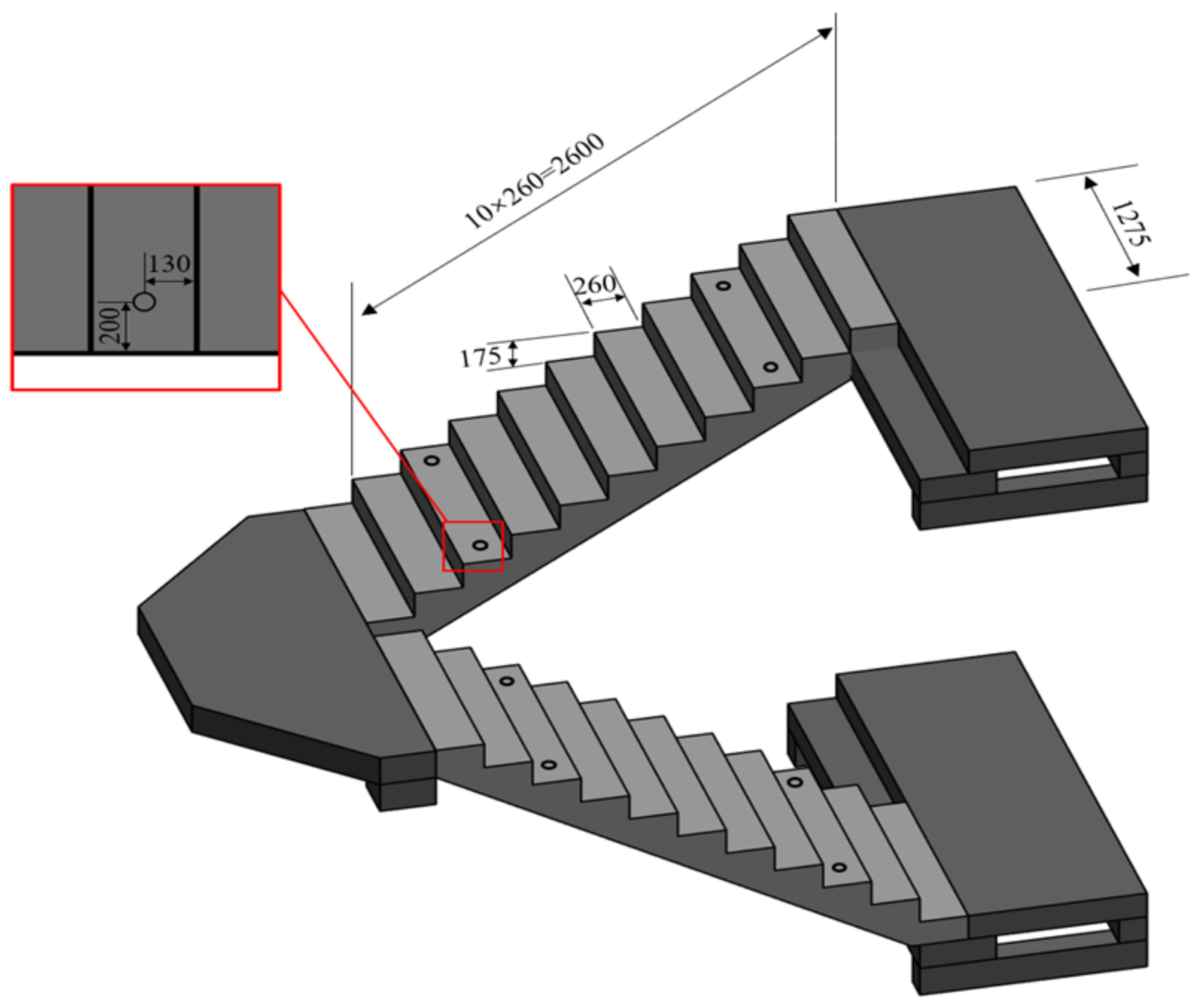
The atlas was divided into two kinds of lifting point arrangement, which were four lifting points and eight lifting points. The lifting points were located at the upper and lower third or fourth steps, and the specific position of the lifting points is shown in Figure 6.

3.2. Classification Prediction Algorithm for Support Vector Machines

The prediction model for the optimal number and location of lifting points of the PC staircase studied in this paper needs to establish an optimal hyperplane to classify the multidimensional dataset, and it should have a strong generalization ability and a high degree of flexibility, which belongs to the treatment of nonlinear problems in high-dimensional space, and it meets the conditions for the applicability of SVMs.
A support vector machine (SVM) is a machine learning model mainly applied to classification and regression analysis problems [30]. An SVM performs classification by finding an optimal hyperplane, so that the data of different categories are as far away from the hyperplane as possible on both sides of that hyperplane, thus achieving the purpose of classification. Because an SVM uses kernel functions, it is able to effectively handle nonlinear problems in high dimensional spaces.
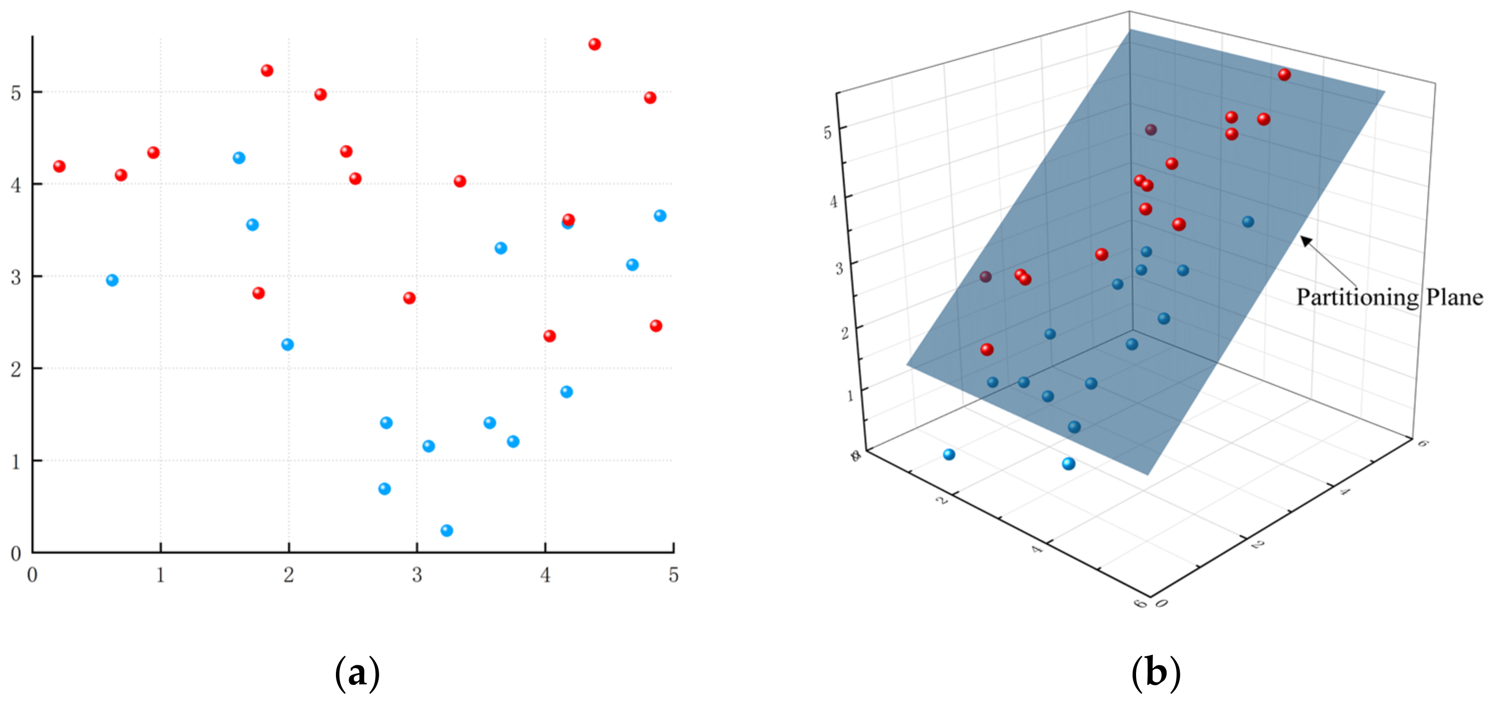
When using an SVM for predictive analysis, it is necessary to determine the appropriate parameters, including the kernel function, the penalty factor C , the radial basis function parameters, and so on. The role of the kernel function is to map the input features into the high-dimensional space and transform the indivisible sample points into divisible sample points, as shown in Figure 7; the core function used in this paper was the Gaussian kernel function (Gaussian kernel), whose expression is:
K ( x , x ) = exp γ x x 2
where x and x are the feature vectors of the two sample points; γ is the kernel function scale parameter, which controls the influence range of the sample points in the feature space. The penalty factor C is used to analyze the tolerance of the SVM model to errors. Later, the k-fold cross-validation method and the grid search method were used to find the optimal γ and C during the model training process in order to obtain better prediction results.

3.3. Hyperparametric Process Optimization

For the prediction of the number and location of PC staircase lifting points, the performance and generalization ability of the SVM model algorithm were mainly affected by the setting of hyperparameters. In order to obtain more accurate results, we needed to optimize the SVM model algorithm by adjusting the hyperparameters.
When choosing hyperparameters, the factor of the ratio of training set to test set must be considered [31,32]. In the training process of a machine learning model, the data set needs to be divided into a training set and a test set in a certain proportion. The ratio of training set to test set has a large impact on the training results. When the proportion of the training set is high, it helps to improve the performance and generalization ability of the model, but at the same time, it may cause overfitting. When the proportion of the test set is high, it may lead to underfitting of the model, which cannot fully learn the patterns and features in the dataset, thus leading to a decrease in the performance of the model. Most of the existing studies use empirical methods, and the division ratio of the training set and test set is usually 70% and 30% [33]. However, they do not analyze the optimal training set and test set division ratio for the corresponding model. In order to improve the reliability of model performance evaluation, this paper adopted the k-fold cross-validation method to determine the ratio of training set and test set.
The k-fold cross-validation method involves dividing the dataset into an equal number of k subsets, selecting one of the subsets as the test set in each cross-validation and the remaining k 1 subsets as the training set for a total of k iterations, and using the average of the k test results as the evaluation parameter [34,35]. The analysis route for k-fold cross-validation of the dataset is given in Figure 8. When the number of samples in the dataset is not divisible by k , the extra samples are put into the last fold. When calculating the average loss for each epoch, the data are converted to vector form, the extra dimension 0 is removed, and the gradient is zeroed out.
In order to realize the prediction of lifting point settings for PC staircases with different specifications, a prediction model was established based on the SVM algorithm, and the model parameters were optimized by the cross-validation method, with the number of folds taken as 4, 6, 8, and 10.The prediction results were evaluated using the root-mean-square efficiency (RMSE), and the closer the RMSE was to 0, the better the model prediction effect is, which is calculated by the formula:
R M S E = 1 k j = 1 k 1 n i = 1 n Y i y i 2
where k is the number of cross-validation folds, n is the number of samples, and y i and Y i are the desired and predicted outputs, respectively.
For SVM models, the parameters to be optimized include the penalty factor C and the kernel function scale parameter γ . The penalty factor C affects the fault tolerance interval of the model; a lower value of C makes the model tolerate more classification errors, leading to looser decision boundaries, which may result in underfitting; when the value of C is high, the model tries to correctly classify all training samples, which may result in overfitting. The kernel function scale parameter γ affects the extent of the spatial distribution of the sample points; a smaller γ makes the decision boundary smooth and suitable for a wide range of classifications; larger values of γ make the decision boundary more complex, capturing finer data structures, but also prone to overfitting. Since the interval of 0.1 to 10 for C and γ has shown good balance on a wide range of datasets and problems and can cover a wide range of model complexity from loose to strict, in order to find the optimal parameter settings, a grid search method was used, and the range of C and γ was set to be from 0.1 to 10.0. In order to ensure the accuracy of model parameter tuning and to avoid overfitting or underfitting, 0.1 was used as a step size for the optimization, and the parameter settings with the smallest RMSE at different cross-validation folds were recorded. The optimization of the SVM model parameters used for the prediction of the lifting point settings is shown in Figure 9, and the optimization results are shown in Table 2.
As can be seen from Figure 9, k was 4, 6, 8, and 10 in the four cross-validations, the maximum value of RMSE was 0.360, the minimum value was 0.254. The RMSE decreased with the increase in the penalty factor and the kernel function scale parameter, and the minimum RMSE values were all obtained at the penalty factor of 10.0. As can be seen from Table 2, the minimum RMSE decreased with the increase in the number of cross-validation folds, and the optimization search time increased significantly. When the number of cross-validation folds started from 4 and increased by 2 each time, the percentage reduction in minimum RMSE was 9.4%, 17.8%, and 4.2%, and the percentage increase in optimization search time was 39.7%, 61.8%, and 27.3%, respectively. The minimum RMSE reduction was the largest and the increase in search time was the largest when k changed from 6 to 8. The optimal result were obtained when the cross-validation fold was 10, the penalty factor was 10.0, and the kernel function scale parameter was 7.0, at which time the minimum RMSE was 0.254.

3.4. Algorithmic Technology Flow Diagram

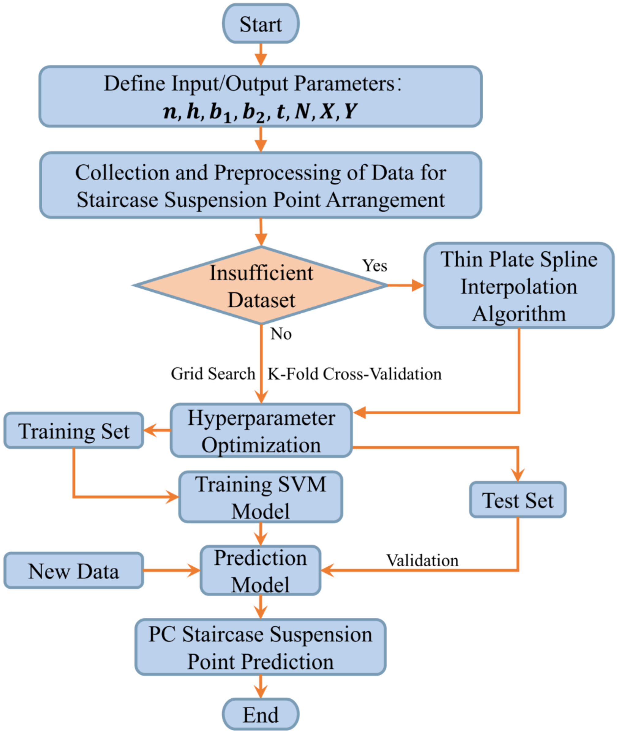
By defining the input parameters, namely, the design parameters of the PC staircase’s tread number n , tread height h , tread width b 1 , staircase width b 2 , and staircase weight t , the output parameters, namely, the number of lifting points N , the coordinates of the lifting point positions ( x , y ) can be determined using the technical flow diagram shown in Figure 10.

4. A Case Study of Machine Learning-Based Stair Lifting Point Setting

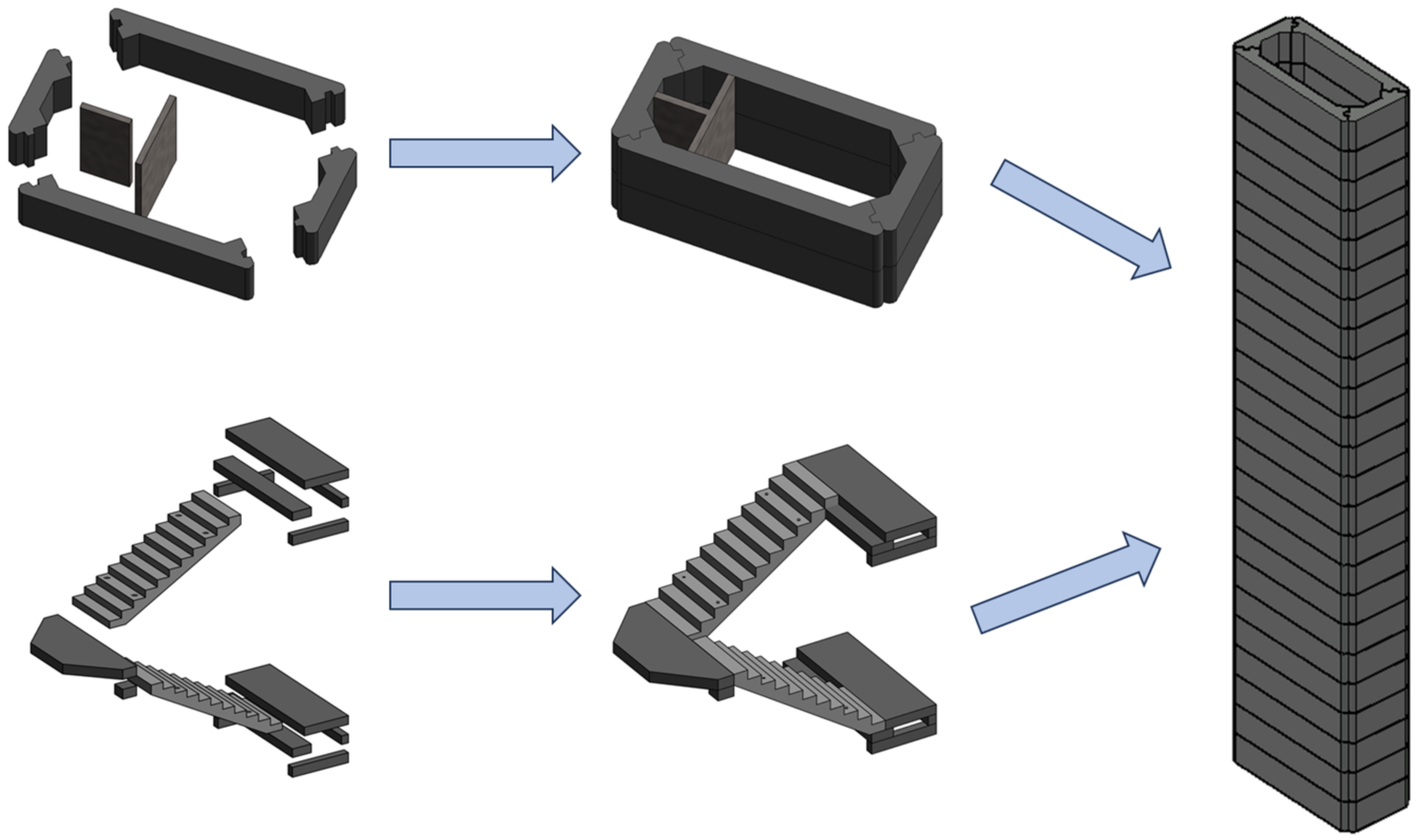
Chongqing rail transit line 27 civil construction 8 project is located in the Nanbin Road scenic area of Chongqing Nanan District. The project starts from Chongqing station (not including the station) through the Nanbin Road station stops at Nanping station (not including the station), with a total of one station and two intervals; the line length is 5385.8 m. The subway station involves the construction of deep shafts in eight places; the shafts are assembled structures and the staircase in the shafts are PC staircases. The assembled component splitting is shown in Figure 11. The space inside the shafts is narrow, the PC staircase is difficult to install, and there are multidimensional spatial constraints. In this section, the 37 m depth shaft was used as the engineering background to apply our method.

4.1. PC Staircase Lifting Point Setting Method

The PC staircase lifting point setting method based on multidimensional constraint space conditions applied to the subway station comprised mainly the following three steps: firstly, the PC staircase was split into two parts: the platform plate and the prefabricated staircase, which were processed by the designated prefabricated component factory, the finished products were transported to the construction site for installation, the two components were preset with pinned key holes, the holes were inserted with bolts for connection, the holes were filled with cement mortar for blocking, and the splitting was as shown in Figure 12. Then, we ran the reinforced concrete staircase lifting point setting model and input the specification parameters of the PC staircase; the main input parameters were the number of treads ( n = 10), the height of the treads ( h = 175 mm), the width of the treads ( b 1 = 260 mm), the width of the staircase ( b 2 = 1275 mm), and the weight of the staircase ( t = 1.87 t), We ran the model and output the number of lifting points and lifting point position of the PC staircase. Finally, the number of lifting points and lifting point position data were extracted, the 3D PC staircase model was displayed in Revit according to the lifting point radius, and the technical delivery of PC staircase production was carried out. Calculated by the PC staircase lifting point prediction algorithm based on support vector machine classification, the number of lifting points of the PC staircase in this case was four ( N = 4), and the location of the lifting point was at the center of the third step, 200 mm from the edge of the ladder section ( x = 130,   y = 200).

4.2. Thin-Plate Spline Interpolation Algorithm

When predicting the number and location of PC staircase lifting points, the model needed to have high flexibility and strong fitting ability. Also, because there were fewer samples of the original database that could be applied when predicting the number and location of PC staircases, the data points in the multidimensional space needed to be interpolated to expand the sample data, and the expanded data needed to have a high degree of fit.
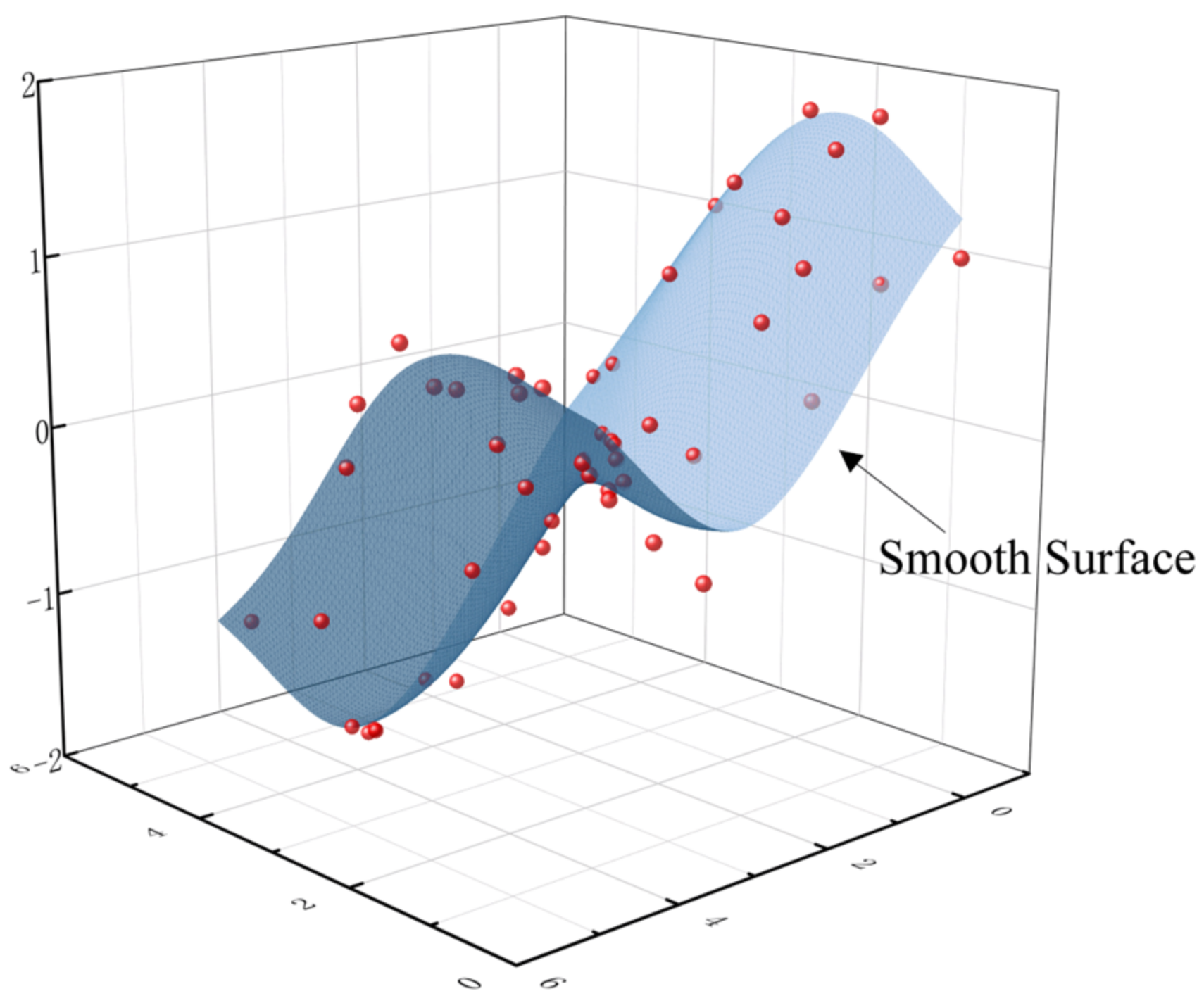
The thin-plate spline (TPS) interpolation algorithm not only provides a high degree of flexibility and strong fitting ability but also has excellent smoothing of the interpolated results, as shown in the continuous surface in Figure 13. It also can effectively handle irregularly distributed data points and can be adjusted by a regularization parameter to control the smoothness of the surface [36,37].
Thin-plate spline interpolation is implemented by solving an optimization problem where the goal of the optimization is to minimize the bending energy of the surface. For the interpolation problem in two dimensions, given a set of control points ( x i , y i , z i ) , where z i is the value at the point ( x i , y i ) , the thin-plate spline interpolation function f ( x , y ) and the basic radial function ϕ ( r ) can be expressed as:
f x , y = a 1 + a 2 x + a 3 y + i = 1 n w i ϕ x , y x i , y i
ϕ ( r ) = r 2 log ( r )
where a 1 , a 2 , a 3 , and w i are coefficients to be determined, i = 1,2 , , n , and r is the Euclidean distance.

4.3. PC Staircase Production Process

After the PC staircase is demolded, it is transported to the precast component factory yard by hoisting and subsequently to the component transportation vehicle, and finally to the precast component yard at the construction site. In this process, precast component manufacturers and transportation units need to control the quality issues. The production process of a PC staircase mainly includes controlling the reinforcement cage, formwork, concrete pouring, vibration, demolding, and lifting.
(1)
The reinforcing cage of a PC staircase should be fully inspected before closing the mold to ensure quality. The reinforcement cage should be tied to determine the size of the protective layer, the degree of curvature, and the spacing of the number of specifications and no more than one tie should be omitted. At the same time, the reinforcement should be smooth, free of oil and rust, and should not be bent. When tying, we need to make sure that the upper and lower longitudinal bars, edge longitudinal bars, edge reinforcement intersections are firmly tied, and the intersections of the middle upper and lower distribution bars can be staggered and tied at intervals. When the stepping reinforcement cage is tied, the bracing iron or tying frame should be set to fix the thickness spacing of the reinforcement, which not only ensures the thickness size requirement but also improves the degree of regularity. Attention should be paid to avoid pin key holes, hanging nails, and other embedded parts. It is recommended to break down the reinforcement material into three parts according to the drawings: staircase upper platform, staircase lower platform and staircase tread for tying. The tied rebar cage is stored in a special rack to avoid deformation. The mold can be closed only after passing the inspection and attention should be paid to the strength when closing the mold to avoid knocking off the protective layer’s pads.
(2)
Before the construction of a PC staircase template, it is necessary to comprehensively check the mold to ensure that there is no gap, and the ends, anti-slip strips, drip strips and the bottom and side mold splices need to be reinforced by electric welding. When applying a release agent, it should be in place, measured and positioned accurately before installation, and channel steel and shaped steel template should be used for reinforcement to ensure that there are no phenomena such as mold rise and displacement. After the reinforcement is completed, each cycle of construction must be completed to check the template’s structural dimensions, plane position, and verticality. Before closing the mold, the sealing tape should be checked to prevent the double-sided adhesive from breaking, shifting, or integrating into the concrete. After closing the mold, the tightness of the bolts should be checked to prevent loosening and slurry leakage during vibration. Before demolding, it is necessary to carry out strength testing of the components to reach 75% of the design strength level and not less than 15 MPa before demolding. In the process of lifting and transferring, impacts, lifting chains, hooks, and stairs not in the same straight line when lifting should be avoided to prevent swinging impact molds or in the process of transferring, impact objects leading to chipping corners.
(3)
Hanging nails need to be checked before installation, to ensure the glue wave is clean; during the installation, not only should the hanging nails required for the workpiece and the surrounding concrete be clean, but one should also ensure that the hanging nails do not exhibit a leakage of slurry phenomenon, and fasten the good hanging nails and molds so that they are in a perpendicular state to ensure that the finished product of the components of the hanging nails are not skewed and the installation is safe for transferring.
(4)
When pouring concrete for a PC staircase, it is necessary to control the quality of cement, concrete ratio, and slump. When the concrete is vibrated, it should be poured in layers, vibrated in layers, and one should master the vibration time and the depth of each vibrator insertion.

4.4. PC Staircase Lifting Process Analysis

The main process of PC staircase construction under multidimensional constrained space conditions is as follows: after the PC staircase is transported to the construction site, the concrete corbel poured in advance at each level during the casting of the side walls of the shaft is utilized as the mounting pivot point of the staircase, the two components, the platform slab and the staircase, are connected by bolts, and finally, cement paste is used to fill in the bolt holes and the assembling joints. The structure of the shaft is shown in Figure 14. The steps of the lifting process are as follows:
(1)
Review the size and elevation of the construction PC staircase components before proceeding with construction. Review the size and elevation of the construction PC staircase components. Simulate the construction process in Revit to check the possible collision; the checking process is shown in Figure 15. Prepare a special construction program for the assembled staircase installation, carry out a second-level technical briefing and a safety briefing to construction technicians, and carry out a detailed third-level technical, safety, and operation briefing to the team.
(2)
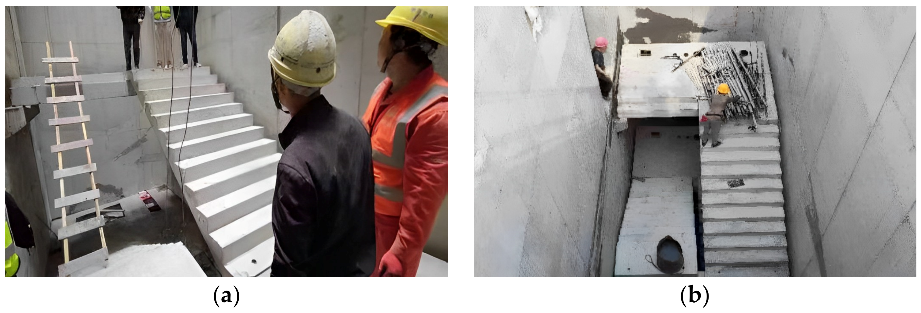
When binding side-wall reinforcement in a restricted space, simultaneously bind the corbel reinforcement, and reserve the straight thread for the corbel reinforcement; after the side wall is poured, chisel away the concrete at the location of the pre-embedded reinforcing bars, bind the corbel reinforcement, and close the mold for pouring the corbel. The poured corbel is shown as (a) in Figure 16. According to the construction drawings, calculate the coordinates and elevation of each staircase, and carry out construction sampling on site after checking.
(3)
If a PC staircase adopts a horizontal lifting method, use bolts to connect the universal lugs with the nuts in the pre-embedded lifting ring of the staircase board, check the unloading buckle ring before lifting, and confirm that it is firm before lifting slowly. When lifting to the surface of the stair board, pause at 0.5 m, according to the direction of the stair board, to adjust the position and ensure the requirements of a slow operation in place, prohibiting a fast and fierce release, so as not to cause damage to the stair board vibration folding. After the staircase board is basically in place, according to the control line, use a crowbar to fine-tune the correction. After the correction of the stair section is completed, fix the pre-embedded parts of the stair section with the pre-embedded bolts of the structure. The staircase board is lifted as shown in (b) in Figure 16.
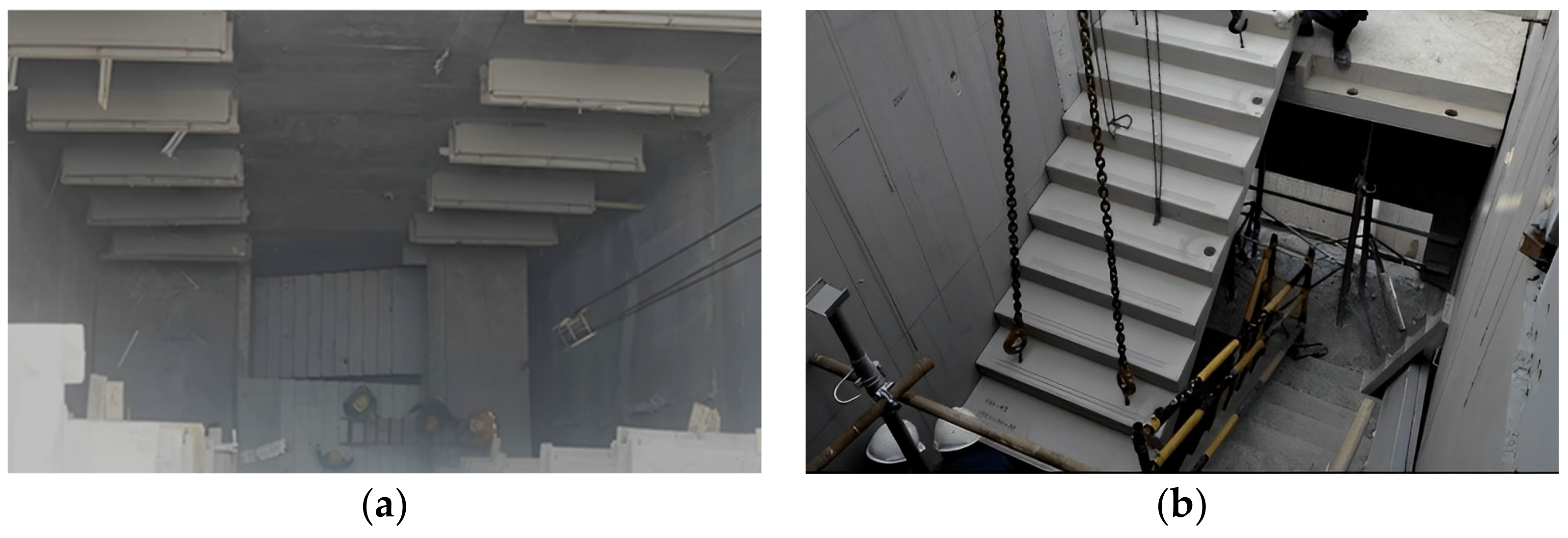
Figure 16. Construction of PC staircase at the subway station: (a) poured corbel on shaft side wall; (b) staircase lifted into position in the shaft.
Sustainability 16 05843 g016
(4)
The connection between prefabricated staircase board and cast-in-place part is treated with cement mortar filling. After the staircase plate is fixed with bolts, cement mortar is filled in the connecting part of the prefabricated staircase plate and resting platform, which is required to be filled from one side of the staircase board to the other side, and the cement mortar can be regarded as having been filled when it is overflowing.
The shaft project at Nanbin Road Station of Chongqing Rail Transit Line 27 adopted the intelligent PC staircase lifting point setting method with multidimensional spatial constraint characteristics of this study and successfully completed all the construction procedures; the whole process of the construction of PC staircases was reasonably timed, with no delay in the construction period. After a comprehensive inspection of the installed PC staircase, it was found that the surface of the staircase was flat, without depression and collision marks, without obvious cracks, in line with acceptance standards. The acceptance process for PC staircases is shown in Figure 17.

5. Conclusions

In order to solve the problems of safety and quality arising from the lifting point setting of PC staircases in different stages of lifting operations, this paper proposed an intelligent prefabricated reinforced concrete staircase lifting point setting method considering multidimensional spatial constraint characteristics, and the specific research results and conclusions are as follows:
(1)
By analyzing the demand for four lifting operations during the production, transportation, and installation of PC staircases, the multidimensional spatial limitations of PC staircases at different stages were clarified, and it was proposed that the setting of lifting points for PC staircases should consider the factors of safety, stability, construction convenience, and economy.
(2)
A database of prefabricated staircase lifting point settings was established, and a thin-plate spline interpolation algorithm was introduced to expand it, which solved the technical difficulty of not being able to make predictions due to insufficient sample data. In order to enhance the reliability of the model performance evaluation, the k-fold cross-validation method was used to determine the ratio of the training set and test set, and the final optimal solution in the number of cross-folds was derived as 10.
(3)
Based on the support vector machine classification prediction algorithm, the kernel function scale parameter and penalty factor were optimized based on the grid search method, which resulted in the optimal kernel function scale parameter of 7.0 and the optimal penalty factor of 10.0. Then, an algorithm for the setting of lifting points of prefabricated assembled reinforced concrete staircase based on the small-sample database was established with these optimal parameters. After inputting the design parameters of the number of treads, the height of the treads, the width of the treads, the width of the staircase, and the weight of the staircase, the algorithm of this paper was run to obtain the number of lifting points and lifting point locations of the PC staircase that satisfied the construction safety, efficiency, and quality.
(4)
The reliability of the precast reinforced concrete staircase lifting point setting method proposed in this paper considering multidimensional spatial constraint features was verified through the construction of prefabricated staircases in deep shafts for assembly construction at the Chongqing metro station, which avoided the problems of cracking and collision of PC staircases. Calculated by the PC staircase lifting point prediction algorithm based on support vector machine classification, the number of lifting points of the PC staircase in that case was 4, and the lifting point location was at the center of the third step, 200 mm from the edge of the ladder section.
(5)
Our intelligent PC staircase lifting point setting method considering multidimensional spatial constraint features is not only applicable to PC staircases but can also be applied to other similar components. The method can be further optimized in future research to make it more compatible with different component types and construction scenarios.

Author Contributions

Conceptualization, G.Y. and Y.Y.; methodology, Y.Y.; software, X.C.; validation, G.Y. and Y.Y.; formal analysis, Y.Y. and X.C.; investigation, X.C.; resources, G.Y. and C.Z.; data curation, T.L. and Y.Z.; writing—original draft preparation, X.C. and Y.Y.; writing—review and editing, G.Y. and Y.Y.; visualization, M.W.; supervision, G.Y.; project administration, G.Y.; funding acquisition, G.Y. and Y.Y. All authors have read and agreed to the published version of the manuscript.

Funding

This work was funded by Fundamental Research Operating Expenses of the Central Universities (2023CDJXY-031) and the Chongqing Urban Rail Express Line Full Life Cycle CIM Technology Application Research and Demonstration Research Project (S20220413).

Institutional Review Board Statement

Not applicable.

Informed Consent Statement

Not applicable.

Data Availability Statement

The data presented in this study are available upon request from the corresponding author.

Conflicts of Interest

Author Yating Zhang was employed by Puyang Longyuan Electric Power Design Co. The funders had no role in the design of the study; in the collection, analyses, or interpretation of data; in the writing of the manuscript; or in the decision to publish the results.

References

  1. Zhao, Y. Features and Construction of Prefabricated Buildings. Adv. Civ. Ind. Eng. IV 2014, 580–583, 2262–2265. [Google Scholar] [CrossRef]
  2. Wang, M.; Yao, G.; Yang, Y.; Sun, Y.; Yan, M.; Deng, R. Deep learning-based object detection for visible dust and prevention measures on construction sites. Dev. Built Env. 2023, 16, 100245. [Google Scholar] [CrossRef]
  3. Yao, G.; Chen, Y.; Yang, Y.; Ma, X.; Men, W. Investigation on Buckling Performance of Prefabricated Light Steel Frame Materials under the Action of Random Defects during Construction. Materials 2023, 16, 5666. [Google Scholar] [CrossRef] [PubMed]
  4. Ding, Y.; Ye, X.; Guo, Y.; Zhang, R.; Ma, Z. Probabilistic method for wind speed prediction and statistics distribution inference based on SHM data-driven. Probabilist. Eng. Mech. 2023, 73, 103475. [Google Scholar] [CrossRef]
  5. Ding, Y.; Wei, Y.J.; Xi, P.; Ang, P.P.; Han, Z. A long-term tunnel settlement prediction model based on BO-GPBE with SHM data. Smart Struct. Syst. 2024, 33, 17–26. [Google Scholar]
  6. Yao, H.; She, J.; Zhou, Y. Risk assessment of construction safety accidents based on association rule mining and Bayesian network. J. Intell. Constr. 2024. [Google Scholar] [CrossRef]
  7. Jiang, P.; Wang, Z.; Li, N.; Song, X.; Chen, Y.; Wang, W. Cumulative deformation and non-coaxial characteristics of fiber and cement-modified iron tailings under the rotation of principal stress. Transp. Geotech. 2023, 43, 101114. [Google Scholar] [CrossRef]
  8. Pan, Z.; Wang, J.; Wang, J.; Tian, M.; Liu, S. Safety Risk Analysis for Prefabricated Building Hoisting Construction Based on STPA-BN. In Proceedings of the Iccrem 2021: Challenges of the Construction Industry Under the Pandemic, Beijing, China, 16–17 October 2021; pp. 171–180. [Google Scholar]
  9. Sun, Y.; Yang, Y.; Yao, G.; Wei, F.; Wong, M. Autonomous Crack and Bughole Detection for Concrete Surface Image Based on Deep Learning. IEEE Access 2021, 9, 85709–85720. [Google Scholar] [CrossRef]
  10. Goh, J.; Hu, S.; Fang, Y. Human-in-the-Loop Simulation for Crane Lift Planning in Modular Construction On-Site Assembly. In Proceedings of the Computing in Civil. Engineering 2019: Visualization, Information Modeling, and Simulation, Atlanta, GA, USA, 17–19 June 2019; pp. 71–78. [Google Scholar]
  11. Duan, Y.; Li, G. Analysis on the Quality Problems and Preventive Measures of Prefabricated Building Construction. In Proceedings of the 2018 7th International Conference On Advanced Materials and Computer Science (Icamcs 2018), Dalian, China, 21–22 November 2018; pp. 411–414. [Google Scholar]
  12. Kong, X.; Wang, S.; Zhang, W.; Ling, X.; Zhao, J. Feasibility of winter construction for prefabricated subway station: Waterproof performance analysis of composite cross-section gasket treated by low temperature. Cold Reg. Sci. Technol. 2024, 219, 104109. [Google Scholar] [CrossRef]
  13. Chen, K.; Chen, X.; Wang, L.; Yang, W.; Qiu, T.; Su, D.; Wu, H. Low-carbon effects of constructing a prefabricated subway station with temporary internal supports: An innovative case of Shenzhen, China. J. Clean. Prod. 2023, 426, 139023. [Google Scholar] [CrossRef]
  14. Chigan, X.; Guo, K.; Li, Q.; Luo, F.; Zhang, Y.; Xu, G.; Xu, Z.; Zhao, J. Design and Optimization Method of Internal Support System for Prefabricated Shaft of Underground Subway Station. In Proceedings of the 2022 8th International Conference on Hydraulic and Civil Engineering: Deep Space Intelligent Development and Utilization Forum (ICHCE), Xi’an, China, 25–27 November 2022; pp. 397–400. [Google Scholar]
  15. Shen, J.; Wu, Q.; Peng, C.; Zhao, S. BIM-based ventilation shaft construction schedule simulation and plan optimization. In Proceedings of the 2020 2nd International Conference on Civil Engineering, Environment Resources and Energy Materials, Changsha, China, 18–20 September 2020; p. 634. [Google Scholar]
  16. Li, L.; Qiu, Z.; Dong, Y.; Du, X. Risk caused by construction of the metro shaft adjacent to building and its control measure. Procedia Eng. 2016, 165, 40–48. [Google Scholar] [CrossRef]
  17. Yang, Y.; Wang, Z.; Xian, B.; Chai, H.K.; Yu, Z.; Zhang, Y.; Zhu, T.; Yuen, K. Baseline-Free Detection Method for Change of Lateral Stiffness of High-Rise Building Based on Statistical Moment Curvature. Struct. Control Health Monit. 2023, 2023, 4373174. [Google Scholar] [CrossRef]
  18. Yang, Y.; Xu, W.; Gao, Z.; Yu, Z.; Zhang, Y. Research Progress of SHM System for Super High-Rise Buildings Based on Wireless Sensor Network and Cloud Platform. Remote. Sens. 2023, 15, 1473. [Google Scholar] [CrossRef]
  19. Yin, J.; Huang, R.; Sun, H.; Cai, S. Multi-objective optimization for coordinated production and transportation in prefabricated construction with on-site lifting requirements. Comput. Ind. Eng. 2024, 189, 110017. [Google Scholar] [CrossRef]
  20. Li, P.; Wang, H. A novel strategy for the crossarm length optimization of PSSCs based on multi-dimensional global optimization algorithms. Eng. Struct. 2021, 238, 112238. [Google Scholar] [CrossRef]
  21. Li, P.; Chen, G.; Qiu, J.; Qian, J.; Ding, D.; Jian, B.; Zhang, X.; Xiong, G. Experimental and numerical investigation into the load-carrying capacity of aluminium alloy H-sectional stocky columns under axial compression. J. Build. Eng. 2024, 87, 108777. [Google Scholar] [CrossRef]
  22. Yang, Y.; Du, H.; Yao, G.; Ma, X.; Men, W. Time-Varying Mechanical Analysis of Long-Span Spatial Steel Structures Integral Lifting in Construction Basing Building Information Model. Sustainability 2023, 15, 11256. [Google Scholar] [CrossRef]
  23. Guo, Z.L.; Gao, S.; Liu, J.E. Application of BIM Technology in Prefabricated Buildings. In Proceedings of the 2nd International Conference On Materials Science, Energy Technology and Environmental Engineering (Msetee 2017), Zhuhai, China, 28–30 April 2017; p. 81. [Google Scholar]
  24. Huang, W.; Lei, Y.; Zhang, S. Research on Existing Problems of Fabricated Building in China. In Proceedings of the Iccrem 2017: Prefabricated Buildings, Industrialized Construction, and Public-Private Partnerships, Guangzhou, China, 10–12 November 2017; pp. 180–188. [Google Scholar]
  25. Alharbi, J.; Bhattacharyya, S. Machine Learning with System/Software Engineering in Selection and Integration of Intelligent Algorithms. In Proceedings of the 2021 15Th Annual Ieee International Systems Conference (Syscon 2021), Vancouver, BC, Canada, 15 April–15 May 2021. [Google Scholar]
  26. Xu, P. Review on Studies of Machine Learning Algorithms. J. Phys. Conf. Ser. 2019, 1187, 052103. [Google Scholar] [CrossRef]
  27. Wang, R.; Chen, G.; Liu, Y. A Dynamic Model of Machine Learning and Deep Learning in Shield Tunneling Parameters Prediction. In Proceedings of the 17th East Asian-Pacific Conference On Structural Engineering and Construction, Easec—17 2022, Singapore, 27–30 June 2022; Volume 302, pp. 1241–1254. [Google Scholar]
  28. Zhang, X.; Lin, X.; Zhang, W.; Feng, Y.; Lan, W.; Da, Y.; Hu, K. Intelligent recognition of voids behind tunnel linings using deep learning and percussion sound. J. Intell. Constr. 2023, 1, 9180029. [Google Scholar] [CrossRef]
  29. Li, P.; Wang, H.; Nie, D.; Wang, D.; Wang, C. A method to analyze the long-term durability performance of underground reinforced concrete culvert structures under coupled mechanical and environmental loads. J. Intell. Constr. 2023, 1, 9180011. [Google Scholar] [CrossRef]
  30. Drucker, H.; Wu, D.H.; Vapnik, V.N. Support vector machines for spam categorization. IEEE Trans. Neural Netw. 1999, 10, 1048–1054. [Google Scholar] [CrossRef] [PubMed]
  31. Ding, Y.; Ye, X.; Zhang, H.; Zhang, X. Fatigue life evolution of steel wire considering corrosion-fatigue coupling effect: Analytical model and application. Steel Compos. Struct. 2024, 50, 363–374. [Google Scholar]
  32. Yao, G.; Sun, W.T.; Yang, Y. Analysis and Identification of Building Construction Accident Risk in China basing Exclusively Database. IOP Conf. Ser. Earth Environ. Sci. 2022, 1101, 072009. [Google Scholar] [CrossRef]
  33. Thai, H.T. Machine learning for structural engineering: A state-of-the-art review. Structures 2022, 38, 448–491. [Google Scholar] [CrossRef]
  34. Jiang, P.; Chen, Y.; Wang, W.; Yang, J.; Wang, H.; Li, N.; Wang, W. Flexural behavior evaluation and energy dissipation mechanisms of modified iron tailings powder incorporating cement and fibers subjected to freeze-thaw cycles. J. Clean. Prod. 2022, 351, 131527. [Google Scholar] [CrossRef]
  35. Ling, H.; Qian, C.; Mang, W.; Liang, C.; Chen, H. Combination of Support Vector Machine and K-Fold cross validation to predict compressive strength of concrete in marine environment. Constr. Build. Mater. 2019, 206, 355–363. [Google Scholar] [CrossRef]
  36. Sibson, R.; Stone, G. Computation of Thin-plate Splines. Siam. J. Sci. Stat. Comput. 1991, 12, 1304–1313. [Google Scholar] [CrossRef]
  37. Dyn, N.; Levin, D. Construction of Surface Spline Interpolants of Scattered Data Over Finite Domains. Rairo-Anal. Numer.-Numer. Anal. 1982, 16, 201–209. [Google Scholar] [CrossRef]
Figure 1. PC staircase lifted to prefabricated component factory yard after demolding.
Sustainability 16 05843 g001
Figure 2. Transportation from prefabricated component factory to construction site.
Sustainability 16 05843 g002
Figure 3. Lifting to construction site’s component yard.
Sustainability 16 05843 g003
Figure 4. Lifting to structural design mounting position.
Sustainability 16 05843 g004
Figure 5. (a) Pre-embedded hanging nail arrangement; (b) lifting point mold opening of a steel mold plate; (c) skewing of hanging nails; (d) corner chipping damage occurred.
Sustainability 16 05843 g005
Figure 6. (a) The specific location of the four lifting points; (b) the specific location of the eight lifting points. (The four corner lifting points of the stairs are symmetrically arranged).
Sustainability 16 05843 g006
Figure 7. Sample point mapping relationship: (a) sample point distribution in low-dimensional space; (b) sample point distribution in high-dimensional space. (The two different colored dots indicate that these dots can be roughly divided into two categories).
Sustainability 16 05843 g007
Figure 8. k-Fold cross-validation analysis flow diagram (lifting points’ prediction).
Sustainability 16 05843 g008
Figure 9. Optimization of SVM model parameters.
Sustainability 16 05843 g009
Figure 10. Technical flow diagram.
Sustainability 16 05843 g010
Figure 11. Detail of the structural components of the fabricated construction shaft.
Sustainability 16 05843 g011
Figure 12. Splitting of PC staircase components.
Sustainability 16 05843 g012
Figure 13. Mapping of a set of discrete points to a smooth continuous surface.
Sustainability 16 05843 g013
Figure 14. Shaft structure.
Sustainability 16 05843 g014
Figure 15. PC staircase construction process simulation and inspection: (a) PC staircase stacking site; (b) PC staircase lifting space; (c) PC staircase installation space; (d) PC staircase connection schematic.
Sustainability 16 05843 g015
Figure 17. Acceptance of PC staircase at the subway station: (a) conducting overall quality checks; (b) clearing the site and securing the PC staircase.
Sustainability 16 05843 g017
Table 1. Sample data of 12 PC staircases.
Tread NumberStaircase Width
(mm)
Tread Height
(mm)
Tread Width
(mm)
Staircase Weight
(t)
Lifting Points Number
81125175.02601.614
81195175.02601.724
91125161.12601.814
91195161.12601.924
91125166.62601.844
91195166.62601.954
161160175.02604.348
161210175.02604.508
171160170.62604.648
171210170.62604.838
181160166.72604.988
181210156.72605.208
Table 2. SVM model parameter optimization results.
Cross-Validation FoldsMinimum RMSEPenalty FactorKernel Function Scale ParametersOptimization Search Time (s)
40.36010.06.5270.03
60.32610.06.9377.11
80.26510.07.4610.05
100.25410.07.0776.37
Disclaimer/Publisher’s Note: The statements, opinions and data contained in all publications are solely those of the individual author(s) and contributor(s) and not of MDPI and/or the editor(s). MDPI and/or the editor(s) disclaim responsibility for any injury to people or property resulting from any ideas, methods, instructions or products referred to in the content.