2. Literature Review
Accuracy is a key factor in determining the correct position with a GNSS sensor. Uradziński et al. [
1] conducted research to determine the accuracy of a mobile phone GPS sensor. They focused on static tests that lasted 1 h, comparing the accuracy of the GPS smartphone with a geodetic GNSS receiver. During the tests, they found that the measurement errors were noted from 1 to 5 cm. For fast static surveying mode, they found that the best results were obtained for 30 min sessions, with the authors reporting results approaching the accuracy of the geodetic GNSS receiver.
Accuracy in GPS-denied areas (difficult-to-reach and ambiguous areas where the signal is lost) can prompt significant challenges in various research scenarios. For this reason, Chen et al. [
2] decided to focus their research on overcoming this challenge. GPS-denied areas can be found inside buildings, in tunnels and under bridges, yet also in densely populated cities. The authors’ method used an ultra-wideband (UWB) signal as a position sensor with high range accuracy and high transmission speed. The authors focused on detecting the exact position when flying with unmanned aerial vehicles (UAVs). The method uses UWB anchors on the ground to determine the position of a UAV moving in the air. Using this method, the authors were able to increase the accuracy from 2.02 m to 0.35 m for attitude determination and from 3.39 m to 0.32 m for altitude determination. There were challenges similar to those encountered in other environments including open fields, particularly in dense urban areas or in forests. Position accuracy errors are a widespread problem in measurements with GNSS receivers. They can be caused, for example, by dense urban areas and even densely growing trees. And it is the effect of trees on the accuracy of GNSS receivers that has been investigated by Lee et al. [
3]. In their research, the authors focused on comparing the accuracy of various types of GNSS receivers using 26 control points in the forest. The correlation values between the forest variables and horizontal position error were significant for each of the GNSS receiver types applied. However, the authors also noted that the trends were not coherent and that the effect of the size of nearby greenery (especially trees) on the analyzed horizontal position error could not be cohesive. Urban areas are also of interest because the signal can be disrupted by numerous GPS-enabled devices, including mobile phones. The problematic accuracy of GPS navigation in cities with densely developed cities was addressed by Ma et al. [
4]. Their researched the negative impact of urban environments on GPS accuracy, which they called GPS environmental friendliness (GEF). They worked with location data from bus journeys. The advantage of these data was that the buses always follow the same route, which allowed them to carry out a large-scale analysis. The authors estimated the GEF using a weighted evaluation strategy, but they had to take into account the fact that different GPS receivers were used to record the data on the buses. Their results were verified by satellite maps, street views and field tests.
From a technical perspective, the challenges investigated under the term of denied area can also be related to an important aspect of signal measurements, namely the speed accuracy. The speed accuracy of low-cost GPS/IMU (the acronym IMU stands for inertial measurement unit) was investigated by Yuan et al. [
5]. In their research, they focused on investigating the accuracy of the velocity from low-cost GPS and how to improve the given accuracy. Firstly, they found that if only GPS is used to obtain velocity, it may cause a large velocity estimation error or even divergence, and they also found that GPS course angle (CGA) plays a significant role in GPS accuracy. For this reason, the authors developed a velocity estimation algorithm. Subsequently, they tested the algorithm without CGA. The summary of their investigation indicated that the poor observability of the yaw angle is the biggest concern to vehicle speed estimation. Fusing the GCA can suppress the potential divergence of the yaw angle, and the speed estimation accuracy is obtained at a more appropriate level.
The accuracy of GPS measurements is supported by a variety of methods and technologies. On the one hand, numerical and simulation methods and modeling are used as representatives of conventional programming, and on the other hand, programming and machine learning methods and techniques are applied. Simulation and modeling of GPS navigation accuracy is an important topic that helps to determine the overall accuracy. Wu et al. [
6] tested a dual-antenna Global Positioning System (GPS). Their research required an analysis of the attitude measurement principle. This analysis provided them with an error estimation model. The predicted, the inner and the outer precision were suggested by them, with the use of simulation methods. The obtained simulation results indicated a required UAV yaw angle error achievement of 1° and that the baseline length should equal at least 1 m. The applicability of the model and algorithm was confirmed. Simulation methods have also been addressed by Moore et al. [
7], who proposed in-flight navigation fidelity prediction for emergency management. The results were compared with over 6000 measurements from GNSS sensors recorded over three days in urban areas of Corpus Christi, Texas. Their validation was statistically analyzed. Modeling based on GPS measurements has also been addressed by Luo et al. [
8], who with his team developed the load correction model. The development of machine learning (ML) and deep learning (DL) algorithms has had a significant impact on many considerations of a scientific and practical nature, including increased interest in the subject of the accuracy and efficiency in GPS measurements. Both of the above approaches, i.e., ML and DL, have been investigated by Aydin et al. [
9], who focused on improving the accuracy of GPS conversion and positioning services. The result of their research is to increase the positioning accuracy of navigation systems by using GPS data through hybrid and ensemble algorithms. Zhang and Masound [
10] addressed the accuracy of GPS localization based on Reinforcement Learning (RL; the area of ML). In their research, they compared the well-known Extended Kalman Filter (EKF) model with RL, where they found that RL had a 50% lower error rate. The EKF among other methods was applied as well by Abdolkarimi and Mosavi [
11]. They have investigated a system that improved prediction of the INS sensor errors at GPS interruptions. Their results were compared with Wavelet Neural Network (WNN), Extreme Learning Machine (ELM) and the already-mentioned EKF.
Improving GPS accuracy is an important task to improve the quality of position data. Ngoc et al. [
12] used data fusion from multiple satellite constellations to improve accuracy. A different approach was taken by Choi et al. [
13], who used average speed to improve accuracy. Modeling and machine learning can also be used in the same way, with Abbasi and Heari [
14] and Rahemi and Mosavi [
15] using EKF, while Kaloop et al. [
16] used three machine learning methods to improve GPS position accuracy. However, it is equally important to determine the accuracy of the GPS. As mentioned earlier, positioning errors can occur in cities with dense development, and it is this issue of determining GPS accuracy in urban environments that was investigated by Merry and Bettinger [
17] and Elhajj and Ochieng [
18]. The relative and precise accuracy of point positioning has been investigated by El Shouny and Miky [
19]. Receiver calibration between different GNSS systems has been investigated by Zhao et al. [
20].
In the endeavor to achieve automotive system safety, the integration of strict, formal methods together with verification and validation techniques is proving to be a formidable approach. The survey of Krichen [
21] explored such methods, highlighting their applications, advantages and limitations (as disadvantages). With respect to identifying the potential impacts of security-related threats on the certainty properties of connected automotive systems, Huang and Kang [
22] presented analytical techniques supporting the verification and validation of safety- and security-related timing constraints on systems. The automotive system behavior model was extended by the vehicle communication protocol and malicious attack models, which facilitate the exploitation of the effects of the adversarial environment on the system.
Having mentioned methods and technologies, commercial instruments should also be considered. Morales and Gamboa [
23] carried out a test of a commercially available GEOTAB (Oakville, ON, Canada) device for fleet management of medium-duty trucks. The authors evaluated the device in real tests, with two test scenarios in which they tried to simulate critical events that do not occur in normal driving. The measured data were analyzed and compared with data from the validated VBOX 3i measuring device. The authors calculated the average speed and position error. The authors’ objective was to determine the acceleration threshold at which the GEOTAB device starts to record data.
The accuracy of the GPS system was evaluated by Engleman et al. [
24]. They focused on testing the GPS system while driving an electric scooter. They tested three scenarios, namely acceleration, braking and driving at constant speed. They compared the measured data from the GPS device with the video recorded from DJI Mavic 2 drones. The authors found that the overall average position deviation from baseline across all devices and the three driving scenarios was 2.04 m. The accuracy and reliability of GPS receivers was assessed by Rychlicki et al. [
25]. In their research, they tested nine different GPS receivers with specially designed software. According to the authors, their research could lead to the evaluation of GPS receivers prior to their use. Other important studies dealing with GPS accuracy include He et al. [
26], who tested the accuracy of different GNSS systems, as well as Ciecko et al. [
27], who tested the accuracy of aircraft positioning based on GPS and radar, and Specht [
28], who investigated the positioning accuracy of a navigation system using a reliability method that was based on real measurements.
Having briefly described applications for the classic transport sector, it is also possible to mention the specific domain that is related to this sector. In addition to their use in transport, GNSSs are also used in other areas such as animal tracking. Research on GNSSs in animal tracking can provide interesting insights that can expand our knowledge and contribute to future research. Abdulai et al. [
29] investigated the accuracy of low-cost GPS receivers; however, their focus was for use in cattle pastures. The battery life of GPS receivers can cause problems, especially for long-term measurements. This issue has been addressed by Akhmadiya et al. [
30] for the purpose of horse breeding. GPS accuracy is problematic for both transport and animal tracking. This issue has been addressed in bird tracking by Schaub et al. [
31].
Freight transport monitoring is an important area of research in the field of safe cargo securing. Previous research has highlighted the need to know the location of the occurrence of acceleration events [
32] due to the need to detect such events that occur during transportation. As it is not appropriate to use expensive and complex sensors for such purposes, the authors of the present study were motivated to investigate the position accuracy of a low-cost GNSS sensor.
Several studies focus on simulations, numerical and machine learning evaluation of the accuracy of the sensors, while the most influential are in-field research. Analyses of the accuracy of the position with in-field collected measurements and their investigation are carried out, as opposed to numerus presentations focusing on simulation and numerical modeling. However, the detailed investigation of such a problem should be explored in more depth. Consequently, this research is based on the classification of the position important for the user of the vehicle monitoring system, where the correct or partially correct and incorrect position of the vehicle from the camera recordings is compared with the position from the GNSS sensors (to compare the obtained inaccuracies). Inaccuracies in the low-cost MEMS-based INS/GPS navigation system due to signal dropouts cause problems in the measurements, as has been mentioned several times in the research described above. The studies in this paper included both routes with full GPS signal coverage and the denied areas, driving through tunnels, as well as urban, mountain and forest areas.
4. Results
4.1. Test Runs in an Urban Environment
This section summarizes the results from the comparison of the accuracy of GNSS sensors A and B. The sensors were compared with each other, yet also with the actual position determined from the video footage. The evaluation procedure is described in
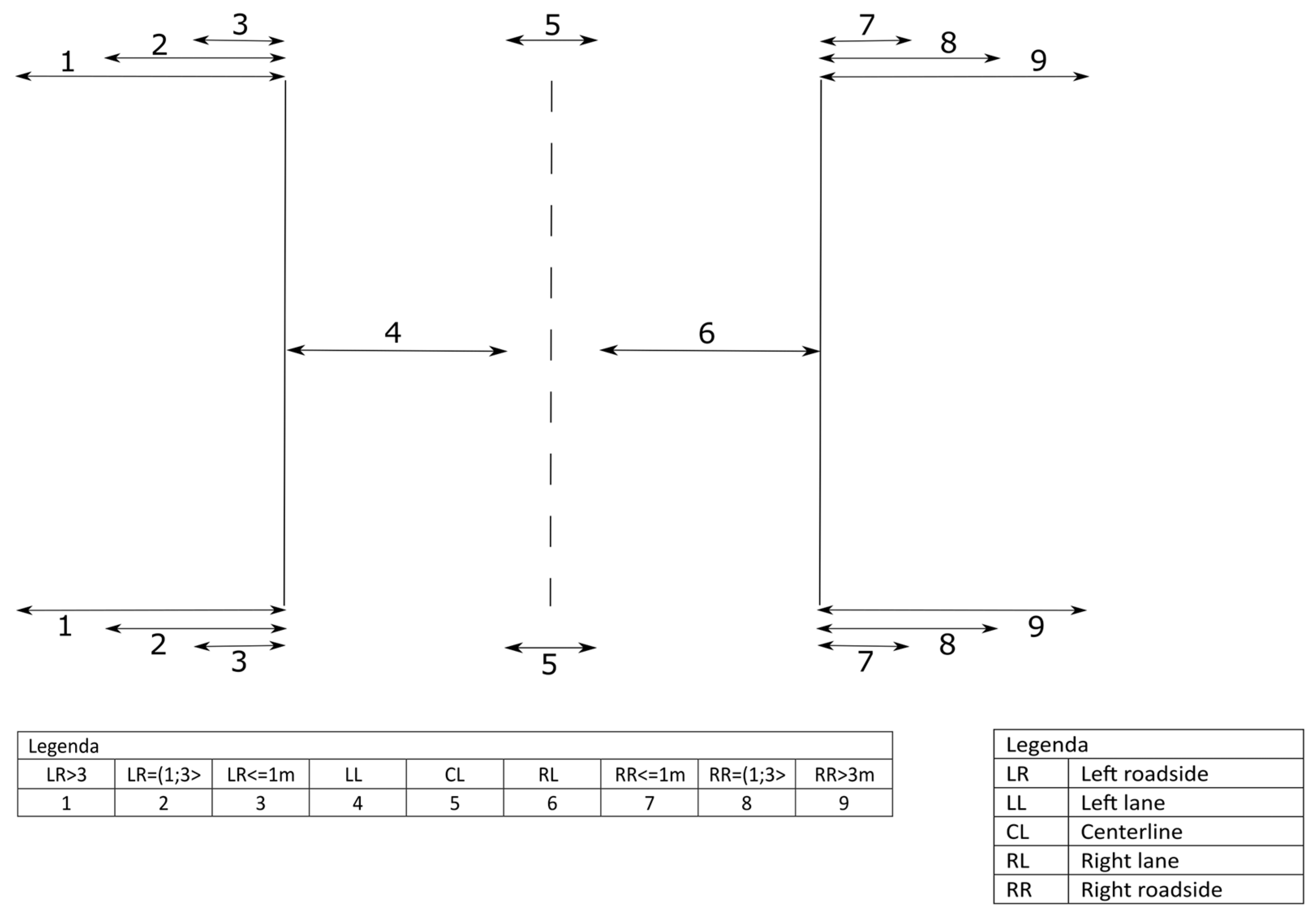
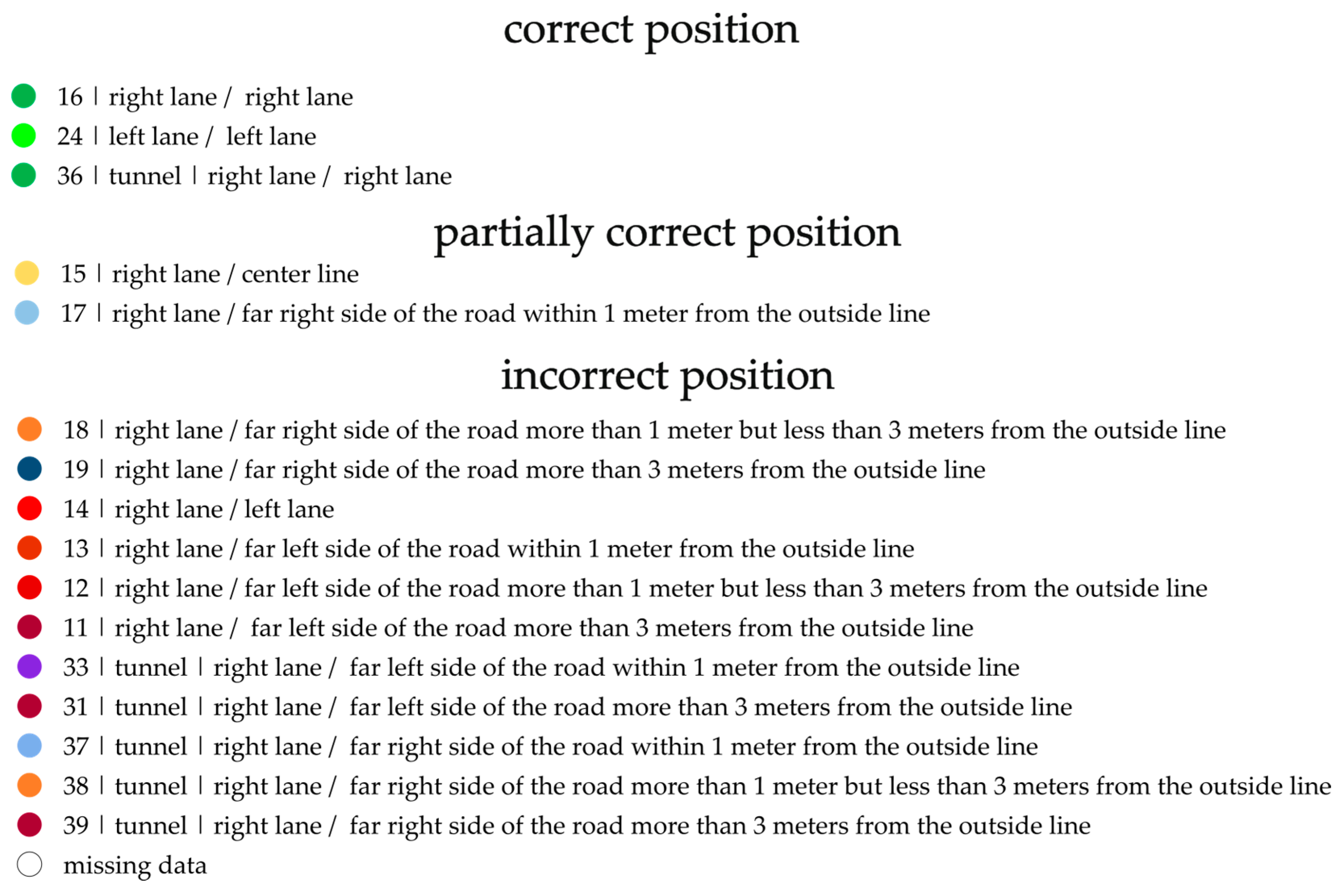
Section 3.3, and the individual meanings of the IDS are given in the text next to the results. The correct position means that the vehicle was in the lane, and the GNSS sensor detected the same position in the lane. Partially correct position means that the vehicle was in a particular lane; however, the sensor detected a position on the center line or on the roadside within one meter from the lane. Incorrect position means that when the vehicle was in the specific lane, the sensor detected a position in the other lane (on a two-lane road) or more than one meter from the roadside.
4.1.1. Urban Test Drives with an Off-Road Vehicle
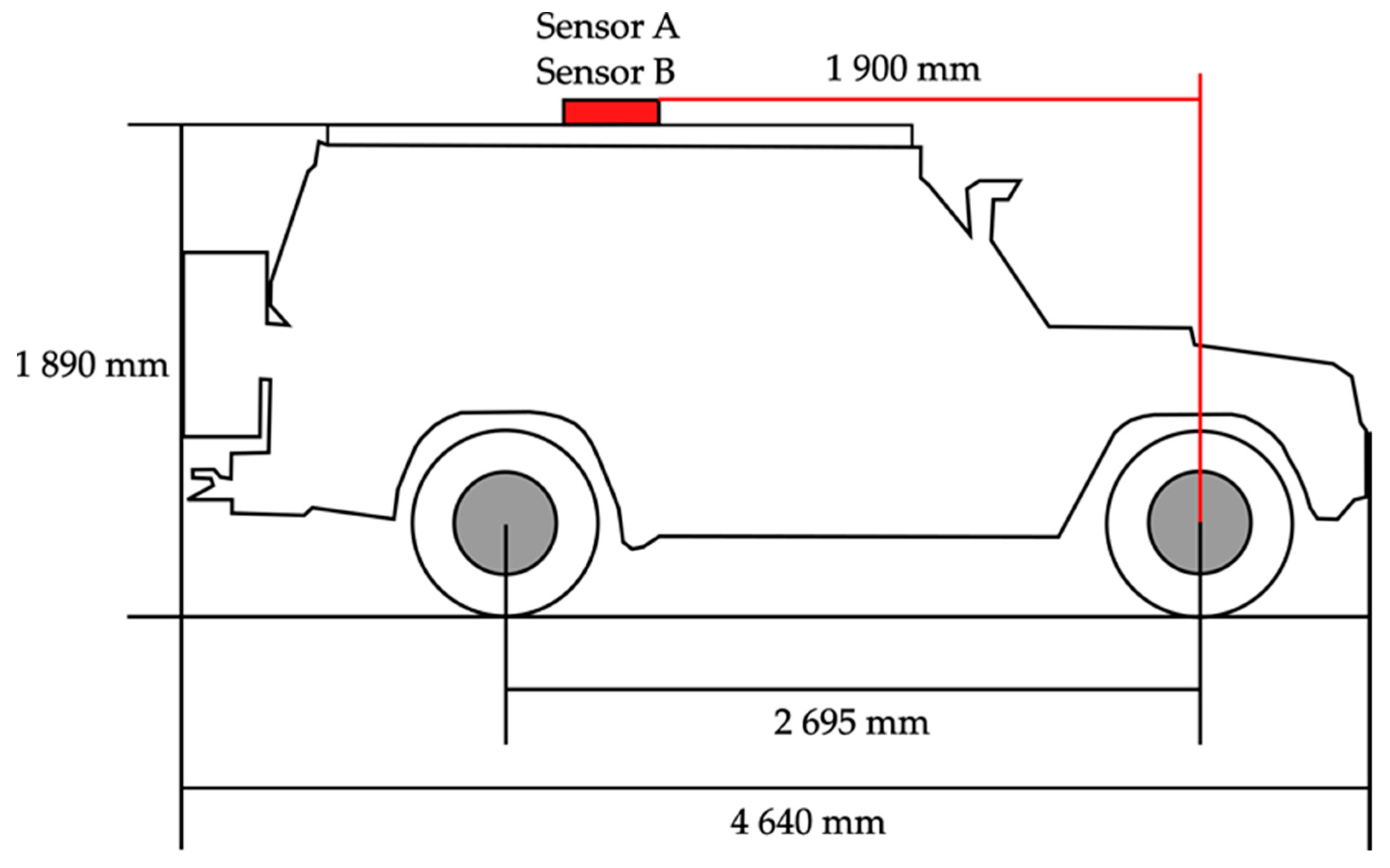
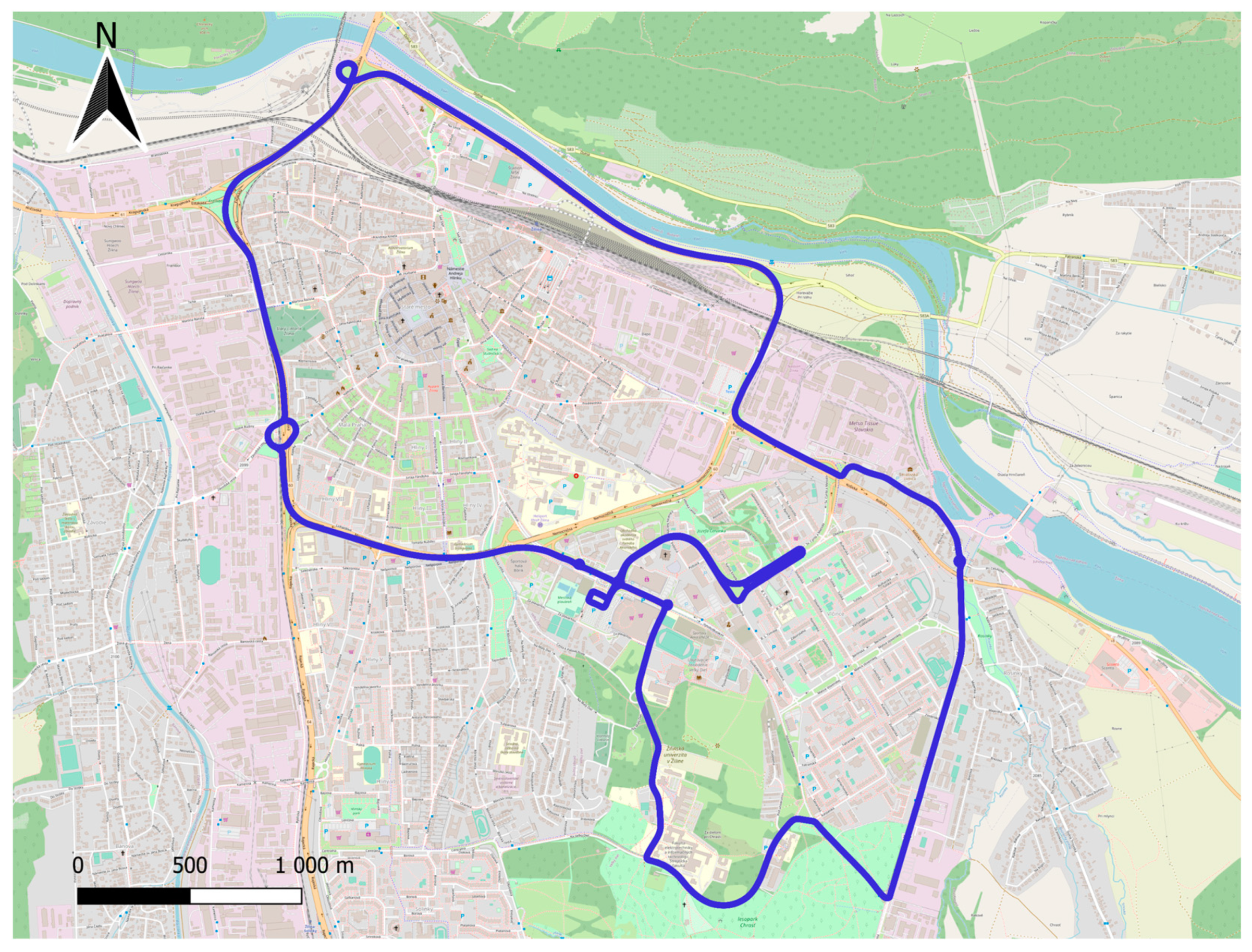
The measurements were taken with a Mitsubishi Pajero, at night, between 22:00 and 01:00, at an average outdoor temperature of 15 °C and an average humidity of 70%. The total driving time was 91 min, and the average driving speed was 44 km/h. In
Table 4, the percentage values of position accuracy from both sensor A and B for all drives are presented.
As it can be observed in
Table 4, the most common position ID is 16, which means that the vehicle was driving on the right side of the road in the right lane, and the sensor also measured that the vehicle was driving on the right side of the road in the right lane. The second most commonly noted ID was 24, which means the vehicle was driving along in the left lane on the left side of the road, and the sensor also measured a position on the left lane that the vehicle was driving along the left side of the road. For combinations of IDs 16 and 24, one can consider that the sensor determined the correct position of the vehicle on the road.
Other IDs indicate a partially correct position. These were the IDs 15, 17, 23 and 25, with 15 being the most numerous and indicating that the vehicle was driving on the right-hand side of the road, and the sensor measured the position of the vehicle on the center line of the road. This was followed by ID 25, which means that the vehicle was on the left side of the road, and the sensor measured the position of the vehicle on the center line of the road. The IDs 23 and 17 mean that the vehicle’s position was measured on the far side of the road within 1 m of the outside line; however, the actual position of the vehicle was in the lane.
The last ID was 14, which means that the sensor was reading the wrong position of the vehicle relative to the actual position, and therefore, the vehicle was on the right side of the road, and the sensor measured the position on the left side of the road.
In rare cases, there were also IDs 13, 18 and 26 on sensor B, all of which meant that the sensor was incorrectly positioned, with the combination of ID 13 meaning that the vehicle was traveling on the right lane of the road, and the sensor measured its position behind the left outer line up to 1 m outwards, and ID 18 meaning that the vehicle was traveling on the right hand side of the road, and the sensor measured its position behind the right outer line more than 1 m but less than 3 m outwards.
4.1.2. Urban Test Drives with a Station Wagon
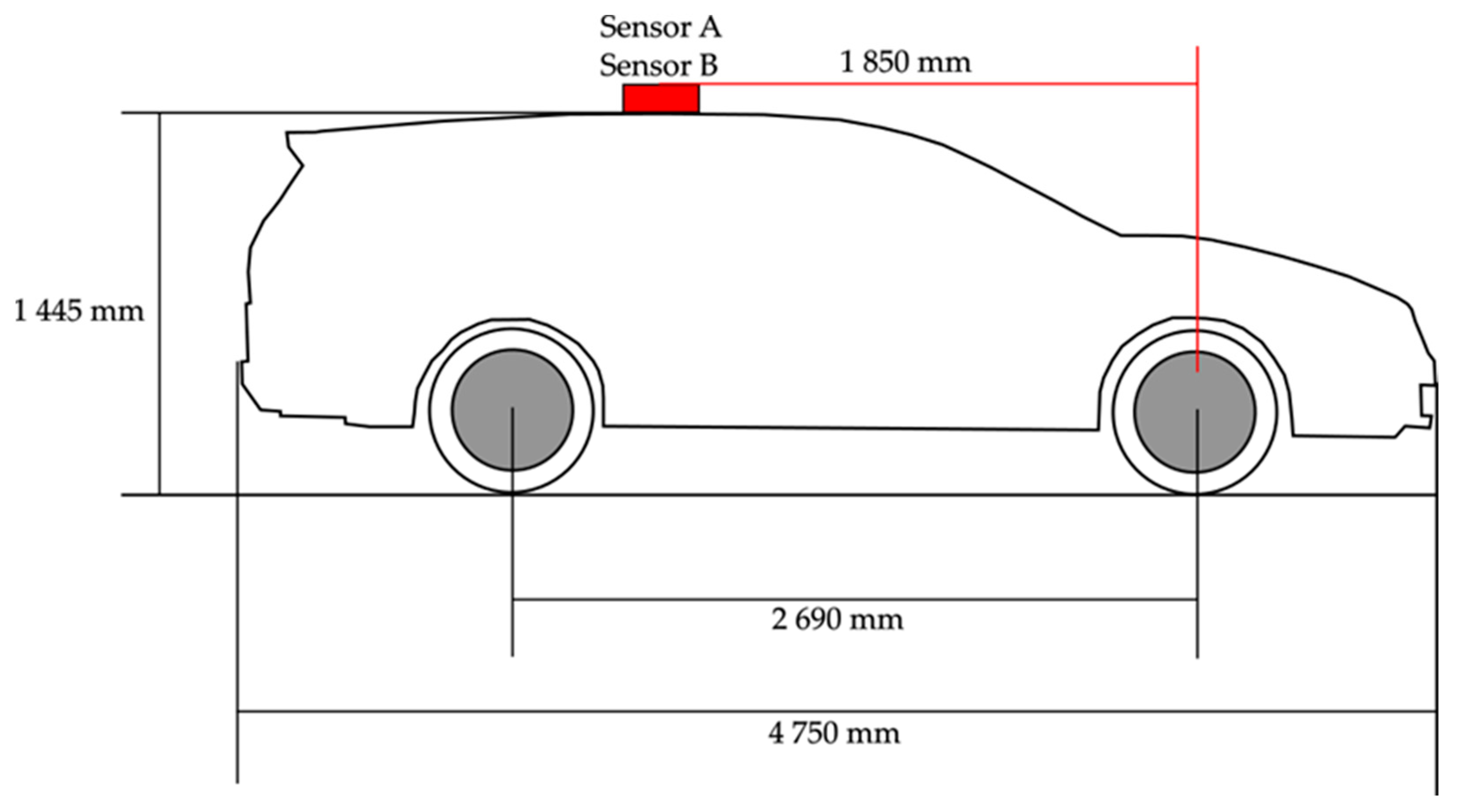
The second test measurements were conducted with the Honda Accord. The measurements were collected at night between 22:00 and 01:00 at an average outside temperature of 18 °C and an average humidity of 62%. The total driving time for these measurements was 84 min at an average speed of 49 km/h.
As in the previous run,
Table 5 shows that the most common ID is 16, followed by 24, which is the correct position. These were followed by the combinations that represent the partially correct position, namely 15, 17, 23 and 25. The combination 14, which represents the incorrect position, is the last one, as in the previous runs, which reached a higher share, since the combinations 13, 18, 19 and 26 reached fractions of percentages less than 0.7%.
4.2. Long-Distance Rides
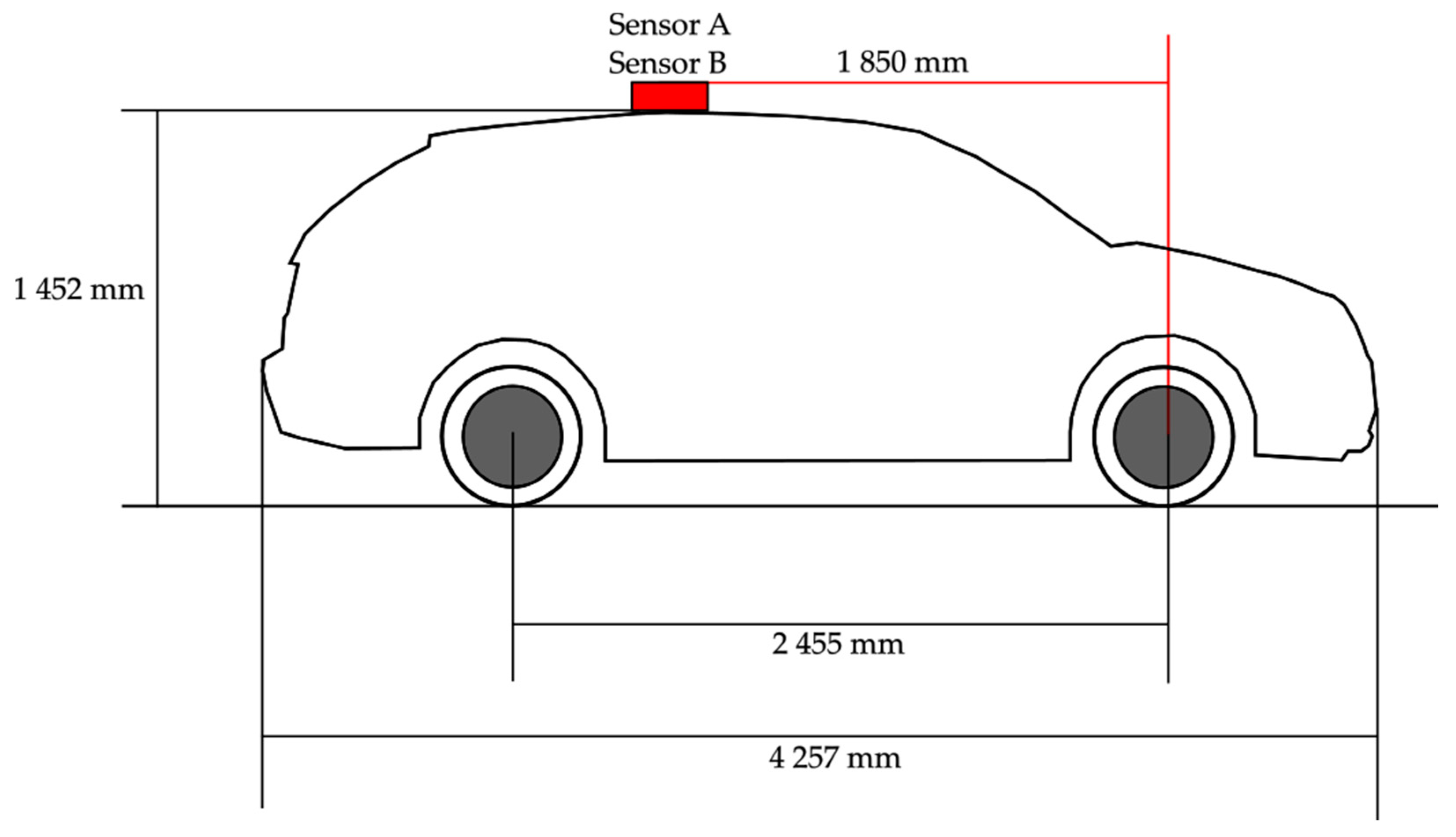
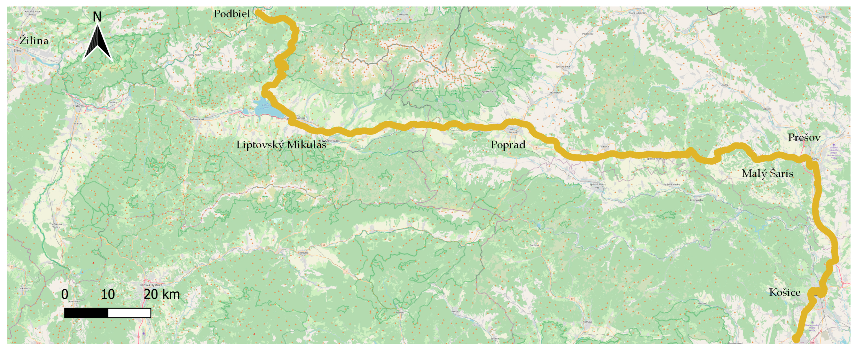
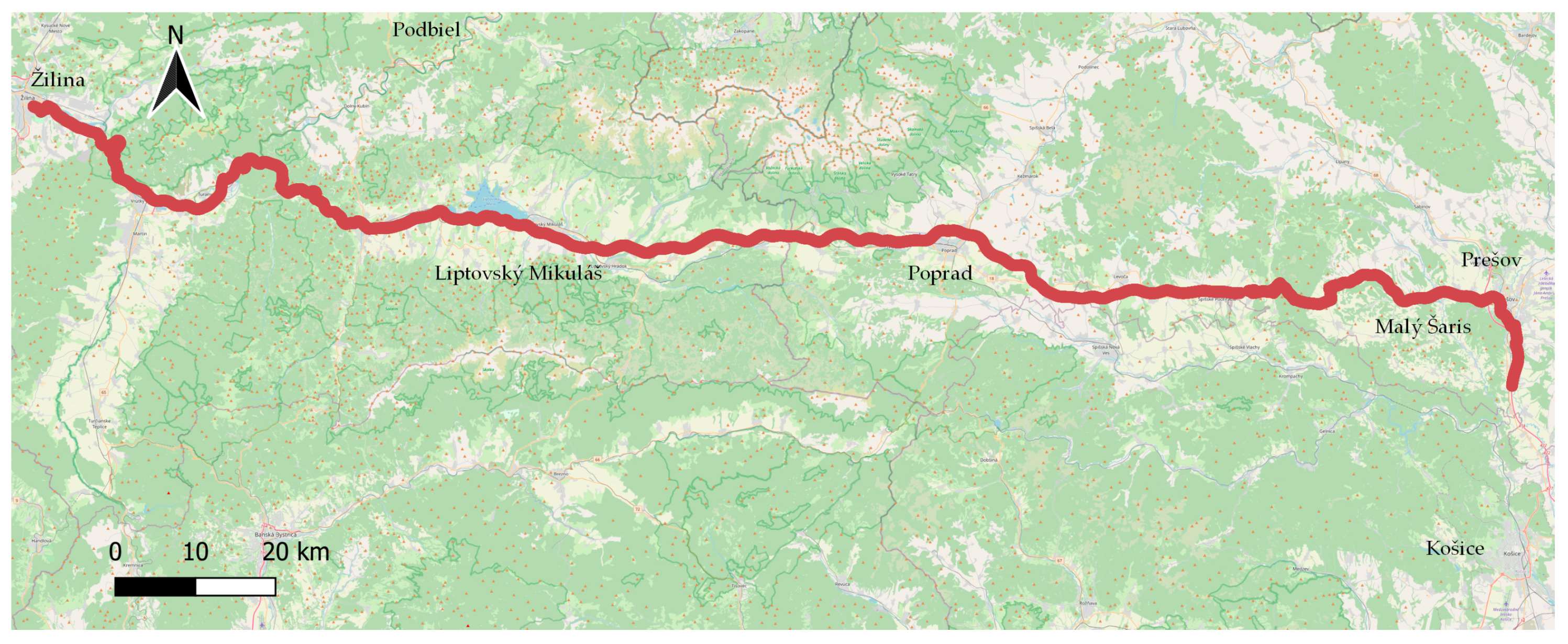
The long-distance test drives were carried out with the same vehicle, i.e., Škoda Fabia. Test routes 1 (Košice–Podbiel) and 2 (Prešov–Žilina) were performed. There is one common section that the vehicle drove through in both cases, namely the section from Malý Šariš (Prešov) to Liptovský Mikuláš. This common section will be analyzed separately from the main routes. Driving took place on class I, II and III roads and on the D1 motorway, alternating with driving through villages and out of villages.
Test route 1 was 233 km long, with a total driving time of 3 h and 6 min at an average speed of 75 km/h. The average temperature during the measurement was 21 °C. Test route 2 was 241 km long, with a total driving time of 2 h and 52 min at an average vehicle speed of 80 km/h. The average temperature during the drive was 18 °C.
An overview of the long-distance drives is shown in
Table 6. In total, two drives, i.e., on test route 1 and test route 2, were conducted, while the common section of these routes, Malý Šariš–Liptovský Mikuláš, was evaluated separately. However, these data were not included in the calculation of the mean differences between the sensors, which is presented in
Section 6. Overall, it can be observed that sensor A achieved higher recording accuracy, but the differences are smaller than for the urban measurements. Smaller differences between sensors occurred mainly due to the fact that sensor A had an advantage in the urban environment owing to the presence of two antennas and an advanced IMU. Of course, this also helped sensor A when driving through tunnels on the highway, but driving through tunnels was only a small part of the overall driving and thus had almost no effect on the overall accuracy.
Comparing the two runs on the common section, it can be mentioned that in this case, there were differences not only between the sensors but also between the drives, even though they were on the same road in the same conditions. It is clear from this that when measuring GNSS accuracy, there are many factors that affect accuracy that cannot be controlled, and therefore, each measurement is unique and cannot be repeated. Despite the rigorous approach to sensor placement and position, there was consistently a difference of more than 5% between runs on the same route at the correct position.
4.3. Test Drives through Tunnels
Due to the need for an analysis of tunnel crossings, an analysis of two motorway tunnel crossings was performed on test routes 1 and 2. The orthophotomosaic of GKÚ Bratislava was used for visualization, while the OSM map layer was used for evaluation. The accuracy of the bridges’ position on the OSM map was verified by data from the Slovak road administration.
4.3.1. Šibeník Tunnel
The Šibenik Tunnel is the first tunnel on the route. It is 591 m long, the second-longest tunnel through which a vehicle has passed, and is located on the D1 motorway section between Jánovce and Jablonov II.
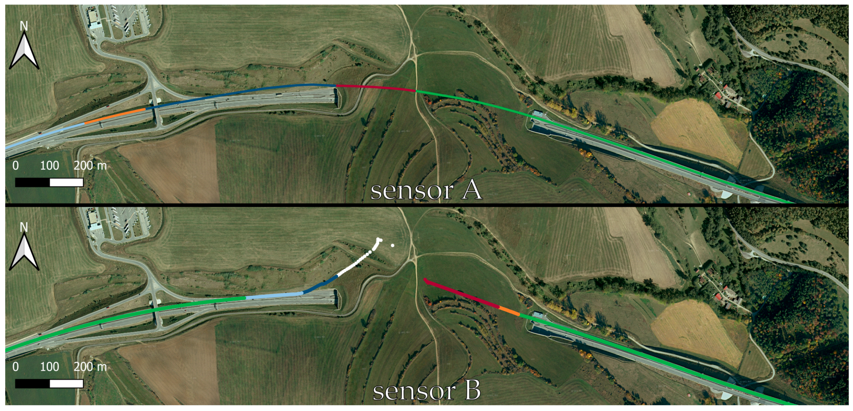
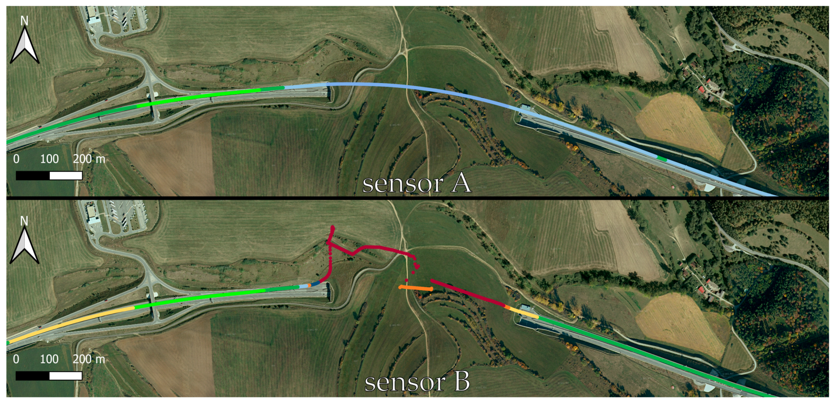
In test route 1, which is shown in
Figure 8, it can be seen that sensor A has moved away from the actual position of the vehicle, but the position has been maintained for the entire length of the tunnel. When leaving the tunnel, sensor A was slower to read the GPS signal than sensor B, and therefore, the latter also recorded the correct position data faster. Sensor B lost the signal after about 300 m. It was only after leaving the tunnel that it started to measure the correct position data again. The colored marks in
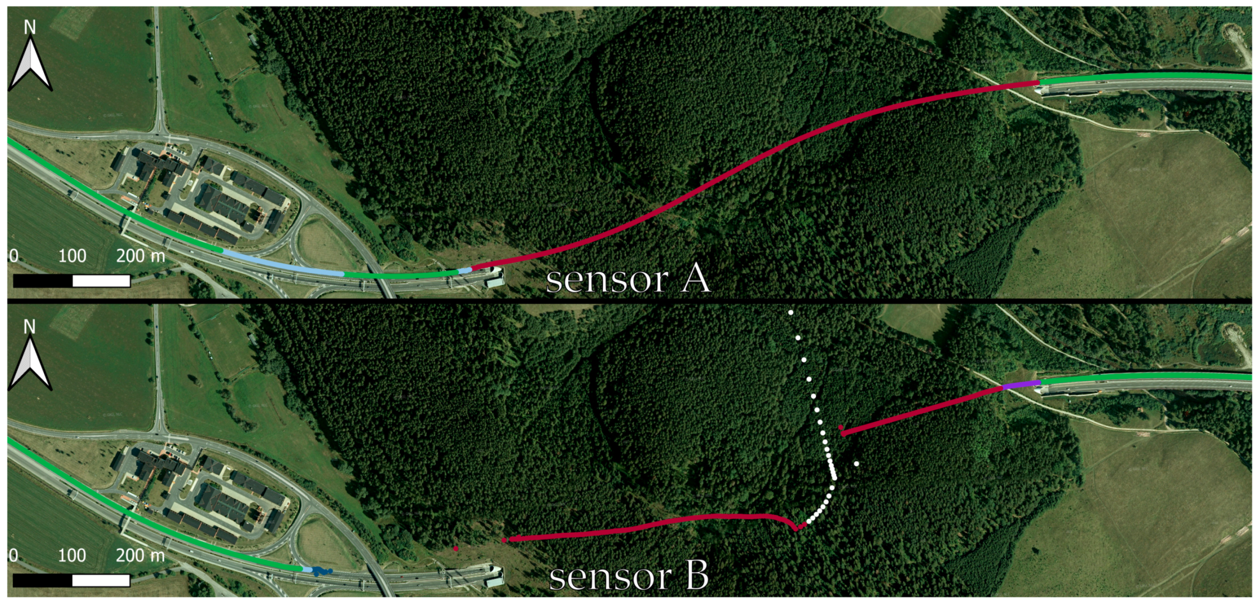
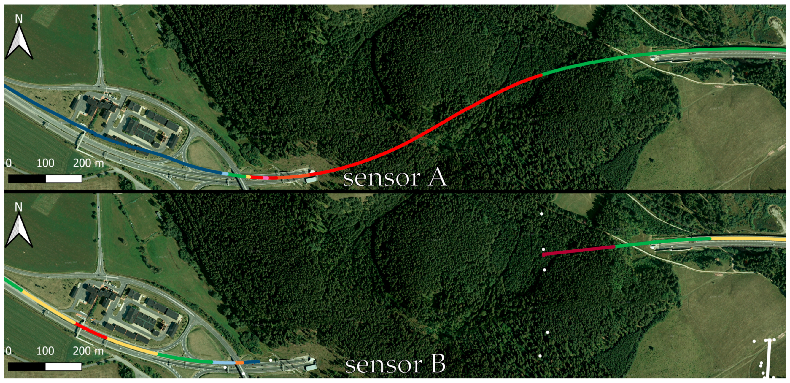
Figure 8,
Figure 9,
Figure 10 and
Figure 11 are explained in
Figure 12.
On test route 2, sensor A was able to measure the position of the vehicle over the entire length of the tunnel as it passed through, despite a minor deviation. Sensor B lost the signal after approximately 280 m and then attempted to find the signal, as shown in
Figure 9. The main difference between the sensors is the loss of signal and hence position data for sensor B at approximately 280 m after entering the tunnel due to the loss of the GPS signal. Sensor A contains an advanced IMU that can record the approximate position despite the loss of the GPS signal. As a result, sensor A can record position data for the entire length of the tunnel, but it does not determine when the GPS signal was lost, and the position data were determined by the IMU.
4.3.2. Bôrik Tunnel
The Bôrik tunnel is the second tunnel through which the vehicle passed. It is 999 m long and is located between Mengusovce and Jánovce. It is also the longest tunnel analyzed.
In test route 1, given in
Figure 10, sensor A was able to record position data for the entire length of the tunnel, despite the tunnel being almost 1 km long, with a slight deviation from the correct position. Sensor B lost the signal after about 200 m from the tunnel entrance and regained it after about 150 m from the tunnel exit, when it also started to record the correct position data. Thanks to the IMU, sensor A recorded position data even without a GPS signal and was able to record the correct position data almost immediately after exiting the tunnel.
The passage through the Bôrik tunnel on test route 2, which is shown in
Figure 11, took a different course than for route 1. Sensor A was able to record the correct position for a longer period, but there were problems with recording the correct position at the exit, which continued after the tunnel exit. Sensor A experienced a loss of signal and therefore position data after approximately 350 m, but regaining the correct position data occurred more quickly than for route 1. Also, for the Bôrik tunnel, we see a clear difference between the accuracy of the data recording between sensors A and B.
4.4. Statistical Analysis of the Accuracy of GNSS Sensors
The comparison with the Honda Accord was chosen as a model example. All recorded IDs were divided into three states, namely correct position, partially correct position and incorrect position; these values represent the frequency. Subsequently, the hypotheses were determined as follows.
The null hypothesis H0 is:
H0. The correctness of the vehicle position record does not depend on the GNSS sensor.
The alternative hypothesis H1 is thus:
H1. The correctness of the vehicle position record depends on the GNSS sensor. The significance level is considered 0.05.
Table 7 presents the input data representing the observed frequency
.
The theoretical multiplicity values must then be calculated according to Equation (1) and collected into
Table 8.
Then, it is necessary to obtain the sub-values of the test criterion, which can then be summed. The sub-values of the test criterion are calculated according to Equation (2) and are presented in
Table 9.
The value of the test criterion
is then obtained as the sum of the partial values of
in
Table 9 according to Equation (3), where
. This value is then compared with the critical value of the chi-squared test, which is calculated based on Equation (4) and has the value of
.
If and are compared, this gives , which means . Hence, since the null hypothesis can be treated as rejected, there is reason to accept the alternative hypothesis. It has been assumed that the variation tested is not random, and its magnitude reflects the true difference between the statistical characteristics being compared. Consequently, the null hypothesis is rejected at the chosen level of significance (supporting hypothesis H1), and it is asserted that the difference between the observed sample frequencies and the expected frequencies is too substantial to occur due to random chance alone. Thus, the observed difference is statistically significant, and the answer based on our research is that there is a difference in measurement quality between sensors A and B.
Lastly, the correlation coefficient is calculated as in Equation (5). means a low degree of dependence.
The same test was carried out on the Mitshubishi Pajero and Škoda Fabia. The value of the test criterion for the Mitshubishi Pajero vehicle was 11,232.785. The critical value of the chi-square test is the same, i.e., 5.99. If we compare and , we find that , and hence . Thus, since the null hypothesis has been rejected, there is reason to accept the alternative hypothesis. The answer based on our research is that there is a difference in measurement quality between sensors A and B. The value of the coefficient is 0.223, so there is a low degree of dependence.
During a long-distance drive in the Škoda vehicle, the value of the test criterion was 1426.650. The critical value of the chi-square test is also 5.99 in this case. Comparing and , we find that , and therefore . Hence, since the null hypothesis was rejected, there is reason to accept the alternative hypothesis. The answer based on our research is that there is a difference in measurement quality between sensors A and B. The value of the coefficient is 0.089, and hence, there is also a low degree of dependence even for long distance driving.
5. Discussion
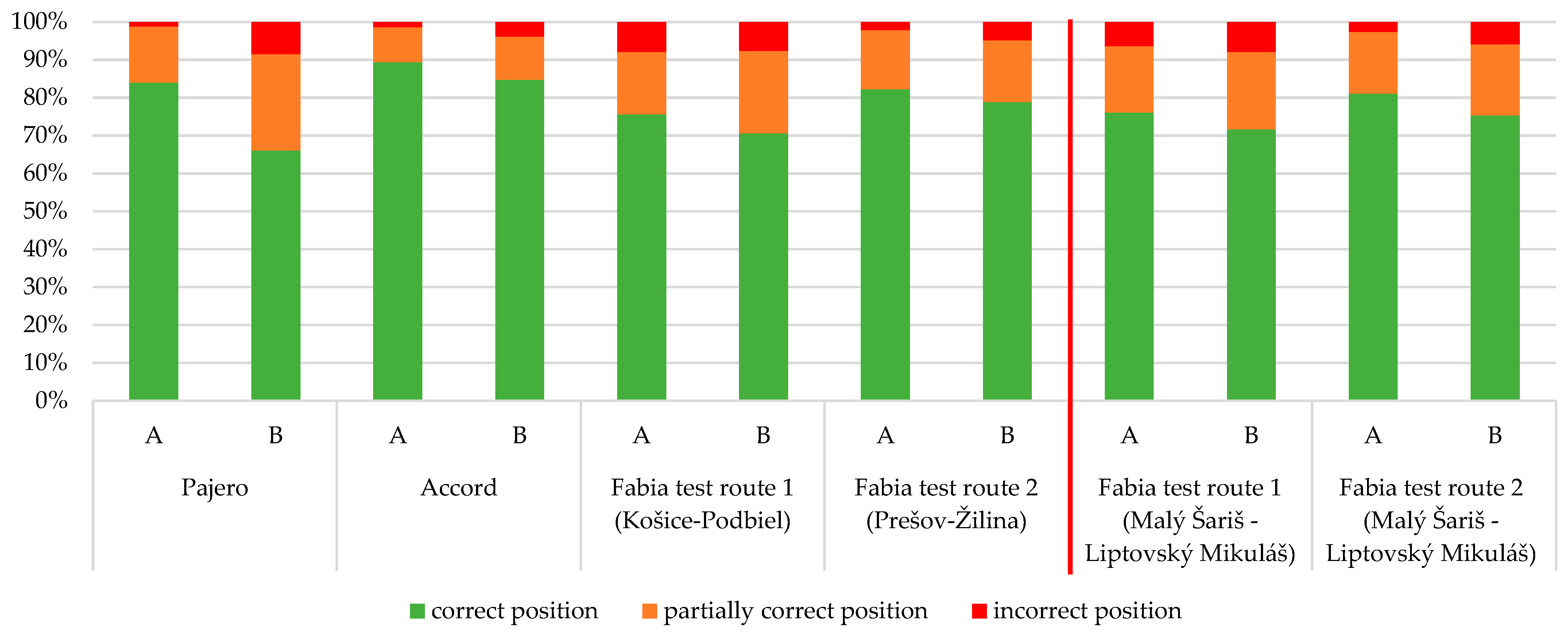
In addition to evaluating the position accuracy data on a run-by-run basis, the average values that were obtained over the entire drive were also analyzed, focusing on the comparison between sensor A and sensor B. In addition to the drives analyzed in
Section 4, the common route section from test routes 1 and 2 (Malý Šariš–Liptovský Mikuláš) is also included in
Figure 13.
Overall, it is evident taking a look at
Figure 13 that sensor A performed better than sensor B in all cases. Such an event occurs due to the technical specifications of the individual sensors. Sensor A contains two antennas and an IMU, which, together with advanced algorithms such as Kalman filtering, ensure accurate coordinate prediction even when the satellite signal is insufficient. Sensor B does not include dual antennas or coordinate prediction algorithms. Therefore, sensor B is characterized by lower accuracy when the signal is weakened, which has resulted in the overall lower accuracy of sensor B.
On average, sensor A reached the correct position for 82.8% of cases, while sensor B did so for 75.1%. Thus, it can be concluded that the difference between sensor A and the low-cost sensor B in determining the correct position is on average 7.7% in favor of sensor A. However, for some applications, such as long-term vehicle dynamics tracking, it is not necessary to know the correct position of the vehicle on the road, and as such a partially correct position on the road is sufficient. Thus, summing up the correct position and partially correct position, it was stated that sensor A was able to determine the position correctly in 96.8% of the data, while sensor B was able to do so in 93.7% of the data. In this case, the difference between the sensors is 3.0%.
During the tunnel runs, the same phenomenon was confirmed in all passes, namely that sensor A was able to record position data throughout the entire pass, while there were data dropouts with sensor B. This was due to the GPS signal loss at both sensors when driving through the tunnel. However, sensor A was able to record position data when the GPS data were lost due to the advanced IMU. As a result, sensor A clearly achieves better results in determining the position accuracy when driving through the tunnels. However, it is important to add that even when two passes were made through each tunnel, the course was always slightly different.
When analyzing the hypotheses in
Section 4.4, it was found that in the three analyses conducted, hypothesis H0 was rejected and hypothesis H1 was accepted. Hence, it follows that in all cases, there was a difference in the quality of the measurements between sensors A and B.
When analyzing vehicle dynamics, it is important to know the position and speed of the vehicle. Without knowing the position and speed of the vehicle, it is not possible to know where certain dynamic events occur, and therefore, it would not be possible to analyze them properly. For this reason, a comparison of the accuracy of the two GNSS sensors on the test routes was performed.
A detailed analysis of the vehicle’s driving dynamics, from which clear conclusions can be drawn, required a large amount of data, which can only be obtained by long-term monitoring. Currently, a sensor that includes a GNSS sensor with two antennas and an IMU is continually applied during drives to monitor the vehicle’s position. However, this sensor requires a constant power supply to operate. In addition, it needs to be constantly connected to a computer that processes and stores the data, since the sensor does not have internal memory. Thus, the whole measurement chain has many components, resulting in high complexity, size and cost, not to mention the complexity of installation and the need for skilled operators. Therefore, this equipment is not suitable for long-term vehicle dynamics monitoring but can be used to verify low-cost sensors.
For these reasons, a low-cost GNSS sensor is more suitable for long-term monitoring. However, the unknown positioning accuracy was challenging and had to be determined by practical measurements.
From the measurements performed, we found that in all cases, the dual-antenna GNSS/INS sensor (sensor A) was more accurate in determining the correct position. Specifically, sensor A was 17.88% more accurate when driving with an off-road vehicle on an urban circuit, 4.55% more accurate when driving a passenger vehicle on an urban circuit and 4.15% more accurate when driving a passenger vehicle on a long route. This inaccuracy and the inconsistency of the results disqualifies the low-cost GNSS sensor from being used in research where higher data accuracy is required, as in [
39,
40]. However, if the incorrect position is compared, it occurs that the differences between the sensors are smaller. Sensor A achieved a difference of −7.31% and −2.44% for the incorrect position for an off-road vehicle and a passenger vehicle on an urban test run, respectively, with a difference of −1.2% on long test runs.
For applications such as long-term monitoring of vehicle dynamics with regard to traffic safety, smart mobility or intelligent logistics, it is not necessary to know the exact position of the vehicle on the road to within a few centimeters. What is needed is to know which road lane the vehicle is in or whether the vehicle is on a roundabout, in a curve, entering an intersection, etc. We can conclude that the low-cost GNSS sensor is suitable for long-term measurements of vehicle dynamics, smart mobility or intelligent logistics from the obtained results.
For long-term monitoring it is necessary to supply power to a given device. From the power consumption measurements over six days, we found that the measurement device combined with the accelerometer consumed 124.35 mAh in one hour. A battery of at least 22,000 mAh would therefore be required to record data continuously for a week. Such a battery has dimensions of, for example, 181 mm × 77 mm × 167 mm [
41], and thus, the dimensions of the whole measuring device would depend on the size of the battery.
The dimensions of the battery and the consequent dimensions of the measuring device may cause limitations when placing the measuring device in confined spaces. Another limitation of this research is the manual determination of position accuracy. Such determination is notably time-consuming. Future research could focus on automating identifications, thereby greatly improving the speed of the process.
The limitation of the research is the fact that the observed percentage accuracy of the position is only valid for specific test routes. The accuracy can be influenced by several factors such as the road network, road conditions, weather conditions and, most importantly, the size of the city in which the measurement is undertaken. The measurements presented here were taken in a small residential area with a lack of high-rise buildings to influence the accuracy, and with a relatively small number of devices receiving, transmitting and sending signals (mainly smartphones) that could influence the results of the measurements. In large cities, megacities and metropolises, the GPS signal quality is more demanding, as tracking the right sender–receiver takes time, or the signal is not available at all, as described by the authors in [
3,
42].
It is clear that the chosen route influences the given results. Therefore, we selected the route to represent the urban and suburban environment. Other routes were chosen for testing in the rural environment. Overall, the results on different routes may vary, but it has also been shown that the results vary for individual runs on the same route. However, an important finding is that although sensor A is statistically more accurate than sensor B, the results show that sensor B still achieves enough accuracy to be used in long-term monitoring of positions of acceleration events for transport safety, smart mobility or intelligent logistics. These findings are valid in general, regardless of the route used. The accuracy of the results can also be influenced by the position of the sensor. For this reason, both sensors were placed in close proximity. The sensors were placed at the same distance with respect to the wheelbase of the vehicle. External factors such as the position of the satellites or weather influence such as temperature, humidity or atmospheric pressure could also affect the accuracy of the measurements. These factors may affect the tests carried out in different conditions; however, they do not affect the accuracy of the measured results because both sensors were exposed to the same conditions during the tests.
In this research, a dynamic comparison of the accuracy of two different GNSS sensors was considered. Such a comparison provides new insights into accuracy, where even a low-cost device can achieve sufficient accuracy to be used in various applications such as improving road safety, smart mobility or intelligent logistics. Research by other authors focusing on sensor accuracy has used different types of measurements. Uradziński et al. [
1] performed a static comparison between a low-cost GNSS sensor in a smartphone and a professional geodetic receiver, where the accuracy could be determined to a few centimeters, which is not possible in dynamic measurements. They found that even a low-cost device can achieve an accuracy from 1 to 5 cm in the static test from the measurement results. Dynamic accuracy testing of GNNS sensors has been addressed by Engleman et al. [
24]. In this case, they investigated the accuracy of a single navigation device, comparing the accuracy of the data with the captured video footage, in the same way as in the case of the actual research. The authors found that the overall average position deviation from baseline was 2.04 m. The dynamic detection of the accuracy of two GNSS devices was addressed by Morales and Gamboa [
23]; however, they investigated the accuracy of fleet tracking devices in terms of improving road safety and did not directly compare the two navigation devices.
6. Conclusions
The comparison of the accuracy of the low-cost GNSS sensor with a dual-antenna GNSS IMU sensor was performed because of the use of the low-cost GNSS sensors in future applications, such as long-term monitoring of vehicle dynamics with respect to transport safety, smart mobility or intelligent logistics.
The small, low-cost navigation device has a wide range of applications in urban logistics, smart applications and road safety. Such a navigation device can collect position and speed data on public passenger transport vehicles, where when paired with an accelerometer, it could also be very accurate in assessing the driving safety of specific drivers. When paired with a GSM module, live location data could be collected, which could be used to track public passenger transport vehicles by waiting passengers. The navigation device in combination with the accelerometer can also be used to detect the state of the load during transport by truck, where it is possible to compare the acceleration coefficients according to the European standard EN 12195-1 [
43], at which the load should to be fixed and the acceleration actually achieved, where thanks to the GNSS device, it will be possible to detect the exact position and speed at which the acceleration has occurred [
32] and to warn the driver of the vehicle what actions should be avoided.
Safety on the roads, also supported by adequate position accuracy without which it would not be known where dynamic events occur, is actively favored by sustainable development in the field of road transport; improved safety enhances environmentally friendly behavior on the road, including not going beyond the bounds of the road, and the provision of appropriately dynamic, sustainable driving contributes to a lower level of fossil fuel combustion while driving. Low costs of providing the opportunities presented are also important. These factors contribute to improving the life of society (improved safety, increased awareness and attentiveness on the road, etc.).
Based on the results found, future research could focus on testing the accuracy of GNSS sensors under different conditions (temperature, atmospheric pressure, rain, including demanding weather conditions) on the same route, and such research would clearly demonstrate whether or how these variables affect the accuracy of GNSS sensors. A low-cost GNSS sensor combined with an accelerometer can be applied in long-term monitoring of cargo transport, which can be used to statistically evaluate the behavior of individual drivers or various other factors, such as the influence of the day of the week, including festivals and holidays, and the number of stops on the achieved accelerations. Such long-term monitoring can examine transportation safety and, in the event of an accident or damage to the load, be used to analyze precisely the cause of an event. To summarize, the implication of the presented research concern enhanced movement monitoring of freight and road networks, which can lead to future investigation of integrity with the increasingly commonplace Internet of Vehicles technology. The implication relates as well to improvements in efficiency, enhancements in driver safety and avoiding a vehicle breakdown. The industrial implications, identified as a result of the analyses obtained, suggest a more efficient and precise functioning of systems based on position accuracy, which will allow a faster response to possible disturbances in the road transport network, and this will be particularly important for applications in smart mobility.
