1. Introduction
At present, nations across the globe are actively pushing for the advancement and utilization of hydrogen power to tackle energy and environmental challenges [
1]. One of the most promising areas for hydrogen energy is in the realm of hydrogen fuel cell vehicles, which are significantly anticipated in the market [
2]. With near-zero emissions, short refueling time, long range, and high performance, hydrogen fuel cell vehicles are suitable for more than ten types of heavy-duty vehicles (HDVs) that can be used in many scenarios, e.g., logistics and delivery, municipal wastewater disposal, mass transit, public transport, and passenger cars [
3,
4,
5]. HDVs have consistently been identified as a truly sustainable source of automotive pollutant emissions. Despite commercial vehicles in China representing only 10.9% of total vehicle ownership, they consume 51% of petrol and diesel, with carbon dioxide emissions accounting for 56% and air pollutant emissions for 80% of total vehicle emissions. The Euro 7 regulation, set to take effect in 2025, and the upcoming National 7 standard in China reflect governmental efforts to shift from diesel heavy-duty vehicles (HDVs) to new energy HDVs to decarbonize the transport industry and contribute to upfront the CO
2 emission crisis and temperature rising worldwide [
3,
6,
7].
Nevertheless, hydrogen presents potential dangers including leaks, fires, explosions, erosion from hydrogen, and the potential for cold temperatures, which pose a major challenge to ensuring the safety of hydrogen storage and transportation [
8]. High-pressure gaseous hydrogen storage technology provides a temporary solution to advance the development of the hydrogen storage and transportation industry by meeting requirements such as weight and volume, energy efficiency, durability, and quick refueling times [
9,
10,
11]. High-pressure gaseous hydrogen storage can be categorized into five groups, including type I to type IV [
12]. Metallic cylinders make up type I containers, while type II vessels are metallic cylinders wrapped with carbon fiber composite materials. Vessels of type III and type IV are either lined with metal or polymer and covered with a composite layer on the outside. The composite outer layer is engineered to prevent structural failure due to damage accumulation from fracture or fatigue [
13,
14,
15], while the liner is designed to withstand high-pressure hydrogen under different thermal and mechanical loads.
In the operational state, high-pressure hydrogen enters or exits all four types of vessels through a longitudinal channel in the opening structure. The opening structure consists of two parts: one is the boss structure, and the other is flow-control devices such as valves, regulators, or nozzles.
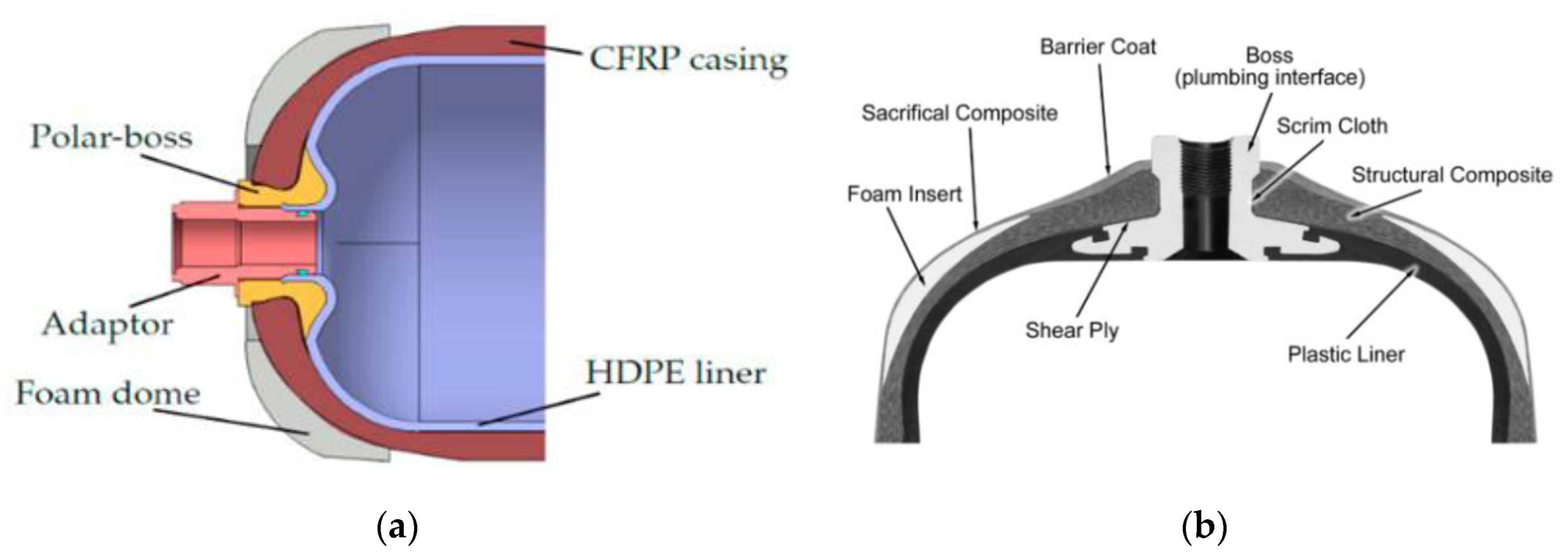
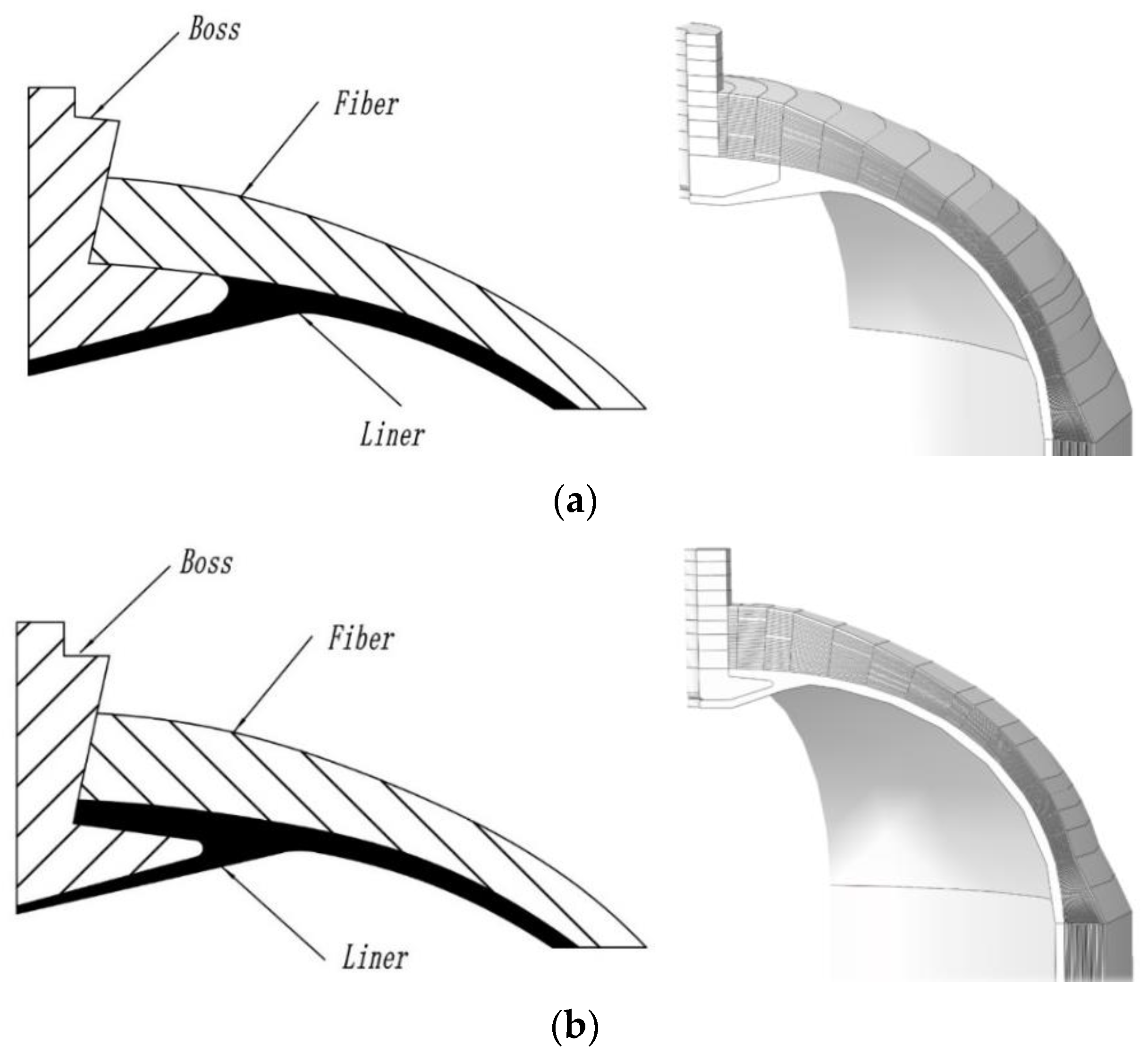
Figure 1a is a schematic diagram of the connection structure between the polymer liner and the boss structure The boss structure includes internal thread to ensure firm contact and tight sealing between the hydrogen filling valves [
16]. Threads can be incorporated on the outside of the polar boss and the adapter can be screwed onto the boss structure. There is a sealing gasket between the polymer liner and the bottle seat that prevents hydrogen from escaping. The high-pressure gas inside the cylinder causes the inner liner to adhere firmly to the boss structure. Compared to the boss structure in
Figure 1a, the boss structure in
Figure 1b is integrated into the bottle seat, eliminating the sealing connection between the bottle seat and the boss structure.
However, fixing the boss structure of the cylinder is always a challenge. In type I and II pressure vessels, hydrogen filling valves are fixed on the metallic body. For type III pressure vessels, the opening of the metallic liner has the same function as the boss structure. However, the use of plastic liner in type IV vessels, such as high-density polyethylene (HPDE) or polyamide (PA), results in hydrogen leakage due to the implementation of composite over boss sections, so how to fix the polymer inner liner to the metal boss structure needs to be considered [
19,
20,
21]. A polar boss is attached secondarily to the liner and the composite layer. The connection to the flow-control devices is also made via the polar boss, such as shut-off valves and thermally active pressure valves [
22]. Due to the ease with which hydrogen can leak out from the plastic liner under high pressure, and the challenge of ensuring the strength of the connection between the metal bottle mouth and the plastic liner, there is a risk of explosion in the fully wrapped carbon fiber reinforced cylinder with a non-metallic liner. Through the investigation of hydrogen safety incidents, it has been determined that piping, fittings, and valves are the components most susceptible to failure, with the boss structure playing a crucial role in these occurrences. One method of connecting to flow-control devices in type IV pressure vessels is to use mechanical threads between the neck and the polar boss fits around the opening of the vessel. Non-metallic materials to metal adhesive bonding can also be used, although achieving adhesive bonding between non-metallic materials and metal, such as plastic in this case, can be challenging, the substantial pressure within the cylinder can aid in preventing slippage of the liner during pressurization and depressurization. Additionally, both the lower and upper surfaces of the flange section may undergo roughening or other treatments to further prevent sliding.
For years, analytical solutions and numerical analysis in finite element analysis (FEA) [
23] were used to investigate the effects of different boss structures. Bouhala et al. [
24] delve into the numerical methods, encompassing conventional shell elements, continuum shell elements, three-dimensional solid elements, and specialized homogenization techniques for multilayered composite pressure vessels. The findings suggest that three-dimensional solid elements provide the highest level of accuracy in modeling composite pressure vessels. Continuum shell elements closely follow in terms of accuracy and computational efficiency, as they strike a balance between the two by combining features of both 3D and conventional shell elements. W. William et al. [
25] used a metallic insert to connect the dome structure to the valve system in type III vessels and conducted a comparative study between the different insert geometries and locations in the dome. The results showed that an insert extending through the dome geometry increased the resulting stress at the junction between the vessel and the dome. Zhu et al. [
26] designed a novel boss structure with sealing grooves, and stop-rotation platforms, which provide close contact between the polymer inner, the boss, and the composite layer under the working pressure. The results showed that the angle of inclination of the stop-rotation platform and the number of sealing grooves in the boss structures can increase fatigue life and sealing performance of the boss structure. Gunyoung Park et al. [
27] et al. concentrated on optimizing the contact surface between the boss structure and the dome. They performed an optimal design of the aluminum boss that met the requirements for structural safety verification. However, Gun Young Park’s study simplified the boss shape as two cylinders assembled, which is quite different from the actual boss model. Nimdum et al. [
28] investigated the influence of the gap, which is induced by debonding between the composite shell and metallic boss during the cooling stage of the curing process on the mechanical behavior of the composite vessel. The results showed that the gap could lead to local bending on the dome area and axial nonlinear behavior response.
The boss structure not only serves to connect to the support frame, but also plays a very important role in ensuring the sealing performance at the mouth of the hydrogen storage vessel [
29]. Due to the large difference between the modulus of elasticity and the coefficient of thermal expansion between the metal boss and the plastic, the cyclic pressure load and thermal stresses generated during the repaid filling process will cause cracks in the joint between the boss and the liner, which may lead to gas leakage. If hydrogen escapes, accidents can easily occur due to its inherent properties such as low minimum ignition temperature and wide flammability range. Hence, a study is essential to analyze the sealing performance of the junction structure in order to provide design recommendations for the boss [
30]. Tao [
31] et al. established a finite element model (FEM) of the bottle mouth structure of type IV pressure vessels using ABAQUS 2020. They investigated how the boss shape and liner thickness impact the deformation and contact stress of the rubber O-ring.
However, these boss structures are mainly used for hydrogen pressure vessels on board, and there is very little research on boss structures used for the vessels on tube trailers [
32]. Compared to on-board hydrogen pressure vessels, the bundle gas vessels used in long tube trailers have a larger length-to-diameter ratio. Large-volume hydrogen storage vessels require large port openings for hydrogen charging and discharging, which necessitates special considerations for liner thickness, exotic threads, and complicated composite wrapping patterns around the polar neck. In addition, the vibrations and deflection generated during transportation impose special considerations on the static strength of the boss structural joint [
33]. In this paper, the geometric dimensions of the boss structure are considered as a key factor. A model of the vessel mouth is simplified and the impacts of geometric dimensions on the structure of the boss are studied. On this basis, the influence of the geometric dimensions on the static strength of the boss structure joints is investigated.
3. Result Discussion
To ensure the connection’s safety between the metal boss, liner, and carbon fiber, an exhaustive structural analysis was performed. This comprehensive analysis covered the evaluation of the boss annular flange and transition region, boss-inner liner connection, and the sealing structure of the inner liner through a detailed finite element (FE) model study.
3.1. Boss Annular Flange
After conducting a comparative analysis of boss configurations within the market, it was observed that these structures share certain attributes, and their primary distinction can be attributed to the annular flange segment. To facilitate the analysis, we simplified the boss structure based on the boss planets and took the geometric dimensions of the polar boss part as the factor to explore the influence on the strength of the boss connection. In this section, the radius of the annular flange is selected as a factor influencing the stability.
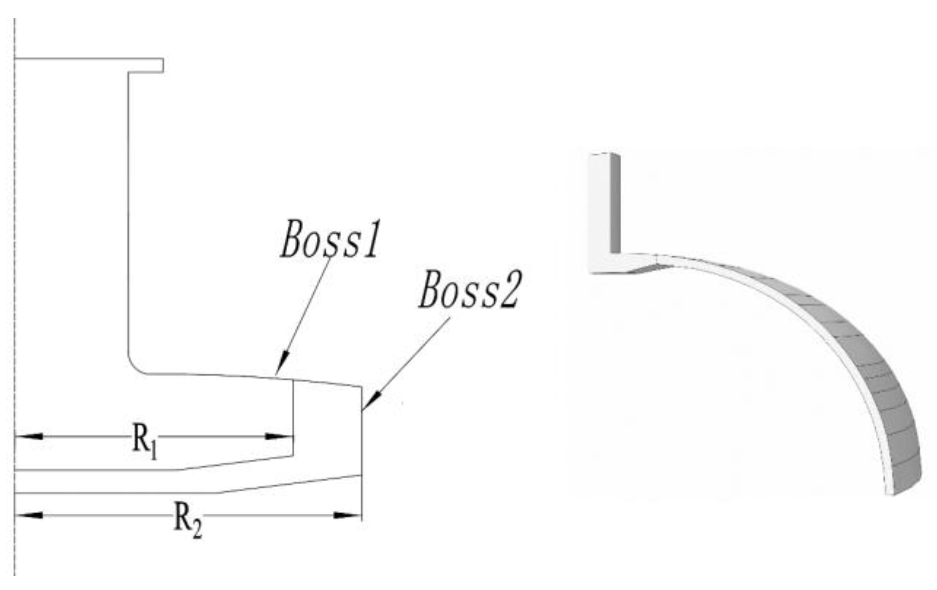
The schematic diagram of the boss structure with different flange radii is shown in
Figure 3, where the flange radius refers to the distance between the axis of the boss structure and the joint of the boss and the liner, and the radii are 60, 70, 80, 85, 90, 95, 100, and 110 mm.
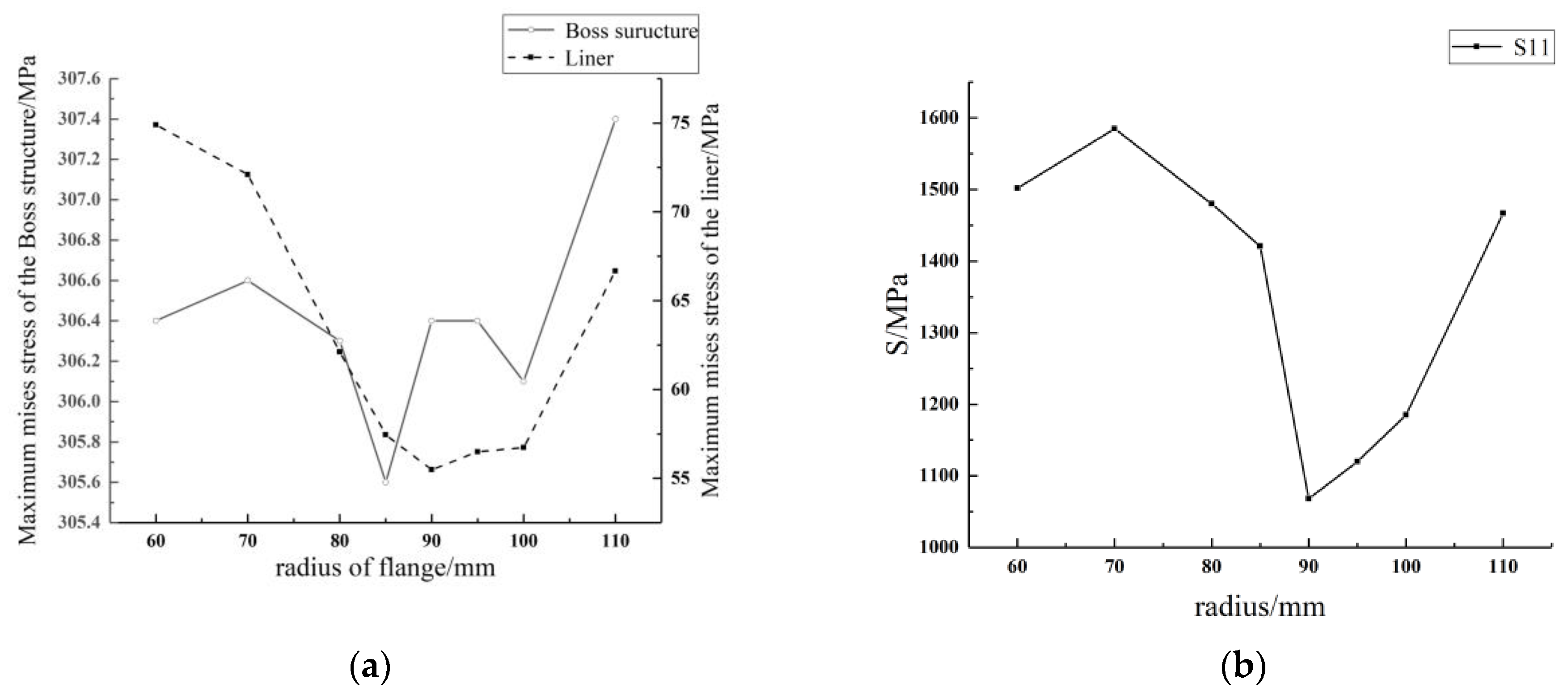
The Mises peak stress under the working pressure of the liner, the boss structure, and the composite layer on the elliptical head was plotted in
Figure 4.
Figure 4 shows that the change in the dimensions of the annular flange has a smaller effect on the stress of the boss structure and the maximum Mises stress of the boss at 305 MPa. However, changing the dimensions of the annular flange has a great influence on the maximum Mises stress of the composite layers and the liner. When the flange radius was increased from 60 mm to 110 mm, the peak Mises stress of the liner first decreased and then increased, reaching the minimum stress at 85 mm. The law of change of the fiber was the same as that of the liner, whose peak principal stresses reached the lowest point at a flange radius of 90 mm.
In summary, both the maximum Mises stress of the liner and the maximum principal stress of the fiber are the smallest when the flange radius is between 90 and 100 mm, which means that the boss–liner connection is currently the tightest. Consequently, increasing the flange of the boss structure improves the stability of the connection between the liner and the boss structure.
3.2. Boss Transition Region
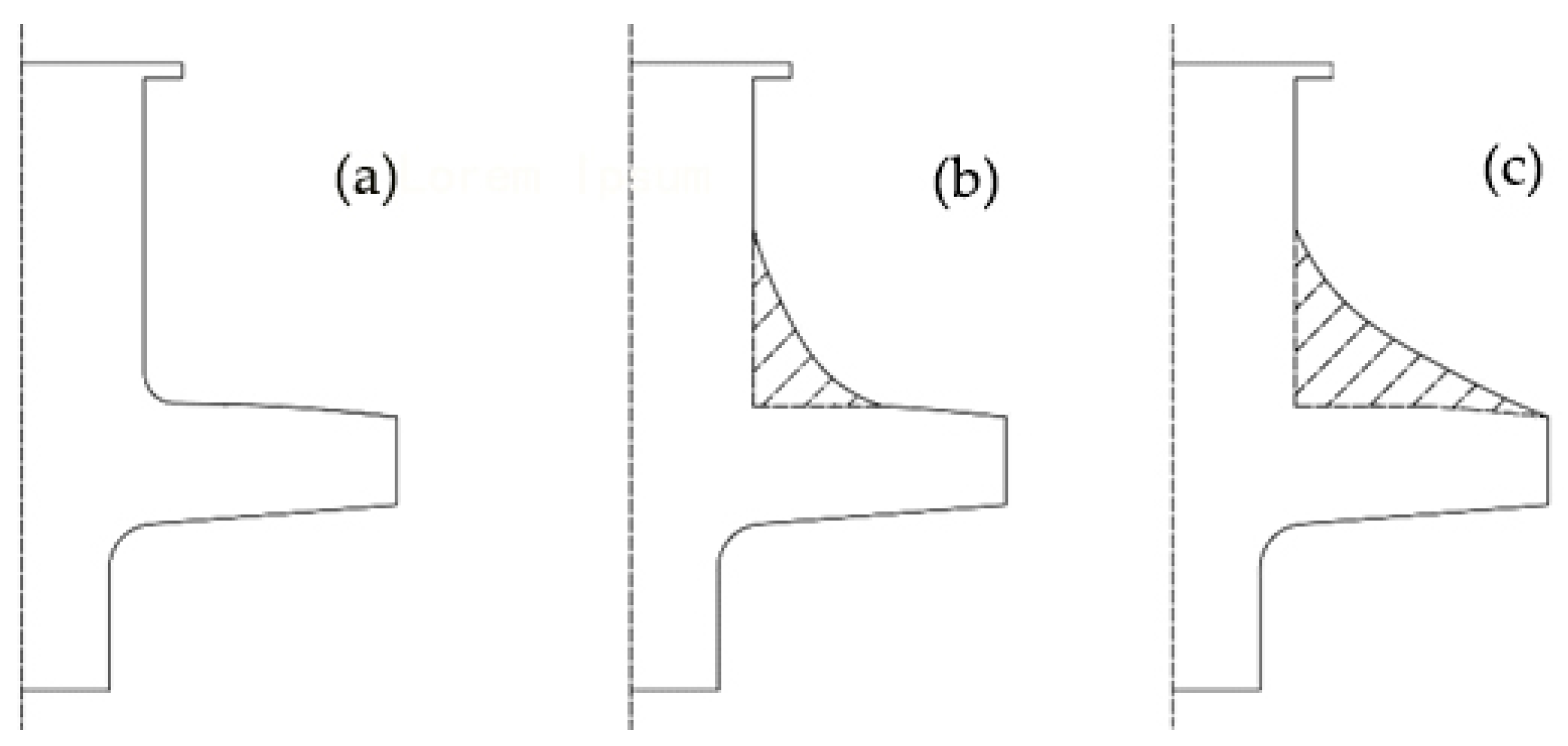
The transition area of the boss structure refers to the part of the upper surface of the boss structure that is in direct contact with the fiber winding layer, and which is also the starting point of the fiber winding.
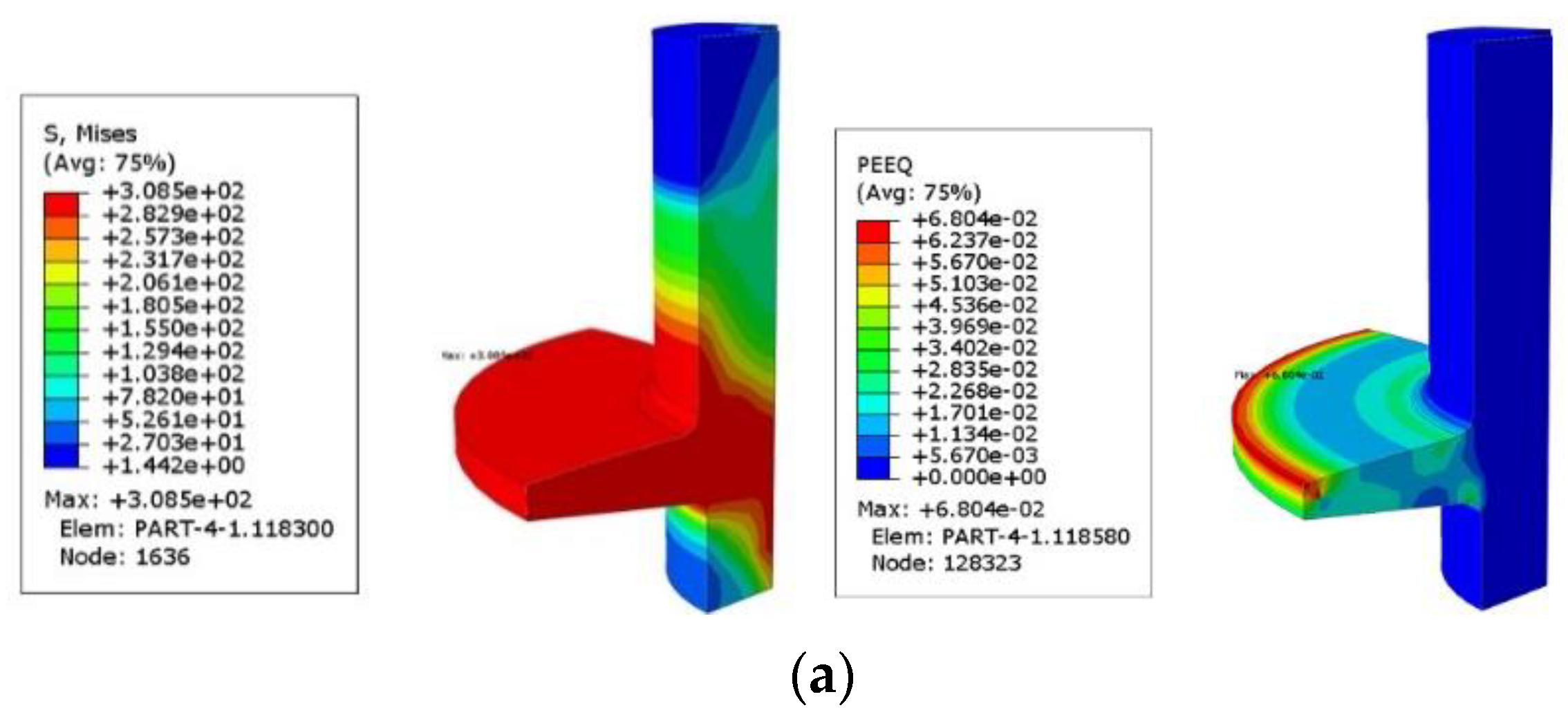
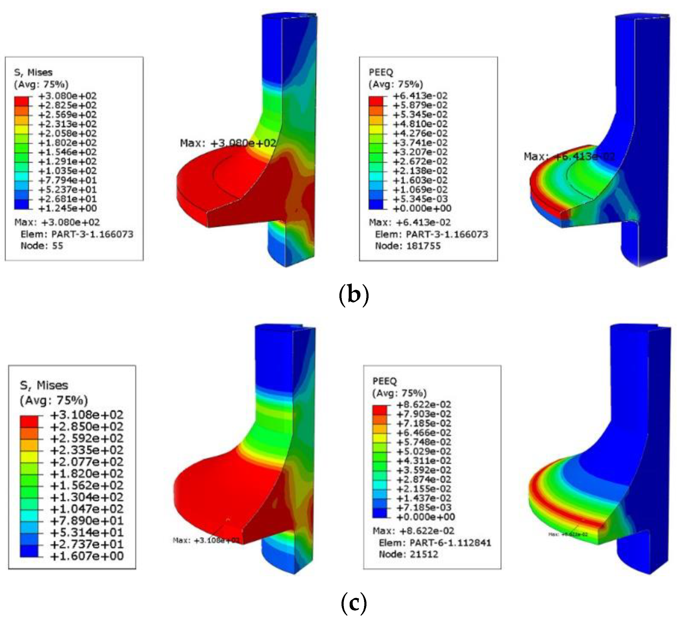
Figure 5 shows a schematic representation of the boss structure with three different curved surfaces. Structure A uses rounded corners for a smooth transition between the neck of the boss and the annular flange, while structures B and C use rounded curves for the transition. The difference between structures B and C is that the curved surface in structure C extends to the edge of the boss flange and the cured surface in structure B extends to the center of the boss flange.
The stress–strain diagrams of the three boss structures under normal working conditions are shown in
Figure 6, where the equivalent peak stress and equivalent plastic deformation of boss structure B are the lowest. It can also be seen that the stress in the connection area between the neck part and the annular flange decreases when the transition area is increased, indicating that increasing the transition area can improve the stress state of the neck part. If the stress distribution in the neck area of the boss structure is improved, the strength of the sealing connection between the boss structure and the metal cylinder valve seat can be increased.
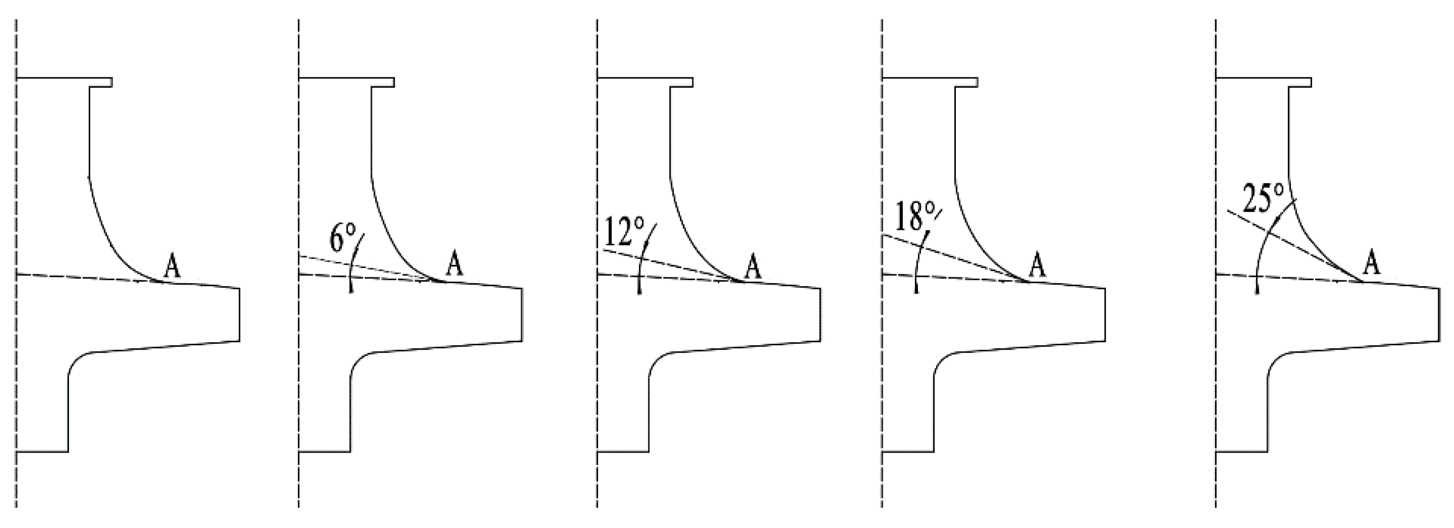
In the above diagrams of the stress and strain clouds, the equivalent stress and the plastic strain are always higher at the edge of the annular flange. To reduce the peak values of equivalent stress and plastic strain at the flange edge, five boss structures were placed on the foundations of model B, as the stress is lowest for model B. To improve the stress distribution at the edge of the annular flange, the entire neck area of the boss structure remained the same. Considering that the stresses generated at the edge of the flange are due to the extrusion of the carbon fiber layer, it is possible to modify the curve of the interface between the neck portion and the annular to minimize extrusion, which is shown in
Figure 7 as point A. All five boss structures are shown in
Figure 7.
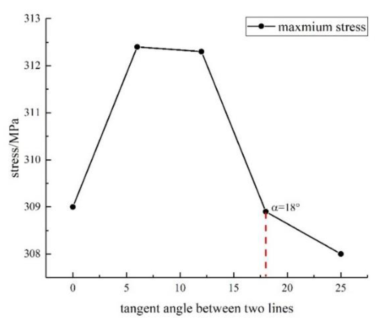
The results shown in
Figure 8 show that the equivalent peak stress at the edge of the flange first increases and then decreases. Therefore, when it comes to designing the contact surface between the composite layer and the metallic boss, it is better to avoid a boss structure with a tangent angle between 0° and 18°. However, the distance between the results is so small that it can be assumed to have only a minor influence on the boss structure.
3.3. Boss-Inner Liner Connection Structure Analysis
In the composite vessel, the boss structure is wrapped by carbon fiber and a plastic liner. Compared to the connection located in the boss structure and the carbon fiber, the connection between the plastic liner and the metal boss offers more design flexibility and can have a greater impact on the connection strength.
To investigate the effect of two different plastic liner mouth structures on the strength of the joint, two 3D models were created to calculate the stress of the boss. As can be seen in
Figure 9, the liner in structure Ⅰ has a generally hemispherical end section with a tapered opening aligned with the annular flange of the metallic boss. Typically, the boss has key ways to fit into the opening of the liner or it can be boned to the liner. In structure Ⅱ, an elongated double-lip seal structure is provided at the opening of the liner, forming an annular recess between the two lips. The boss structure flange is encapsulated in the annular groove to hold the boss structure securely and firmly. The results are shown in
Figure 10.
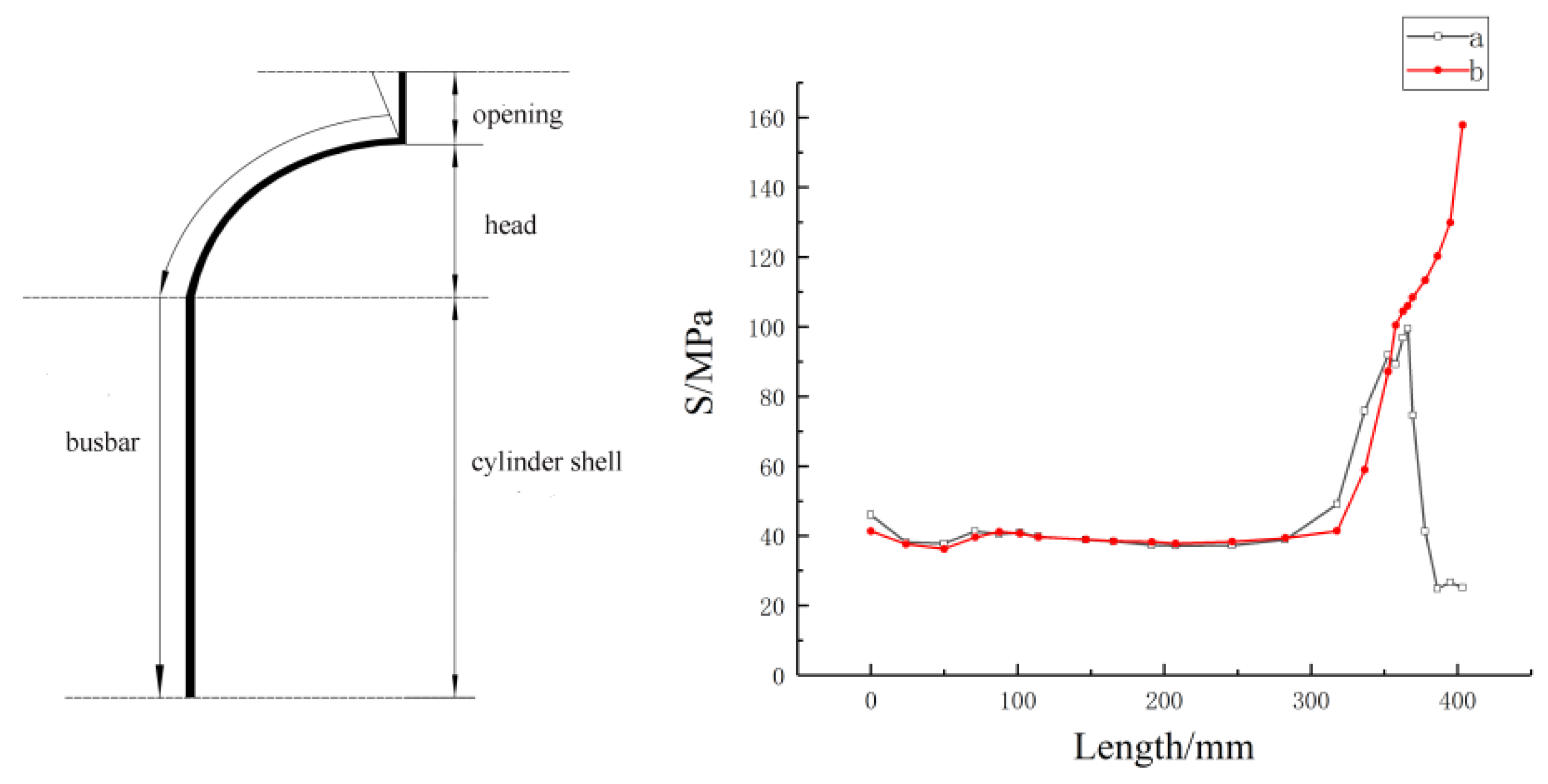
To determine the optimal design of the polar boss part, the maximum stress strength criterion serves as a critical constraint, which means the maximum equivalent stresses in the polar boss and liner part must be less than yield strength and tensile strength under the test pressure. At a working pressure of 52 MPa, the maximum compressive stresses of the boss structure occurred in structures A and B at the base of the annular flange, 315.2 MPa, and 318.8 MPa, respectively, both of which are below the tensile strength of 6061-T6. The Mises peak stress of the plastic liner in the gray area of the stress cloud diagram is greater than the yield strength of the PA6 material of 85 MPa, which does not meet the strength requirements. A Mises stress curve was plotted along the bus line of the liner head, as depicted in
Figure 11. The stress is notably high at the opening of the plastic liner, whereas in other regions of the liner, it ranges between 40 and 50 MPa, well below the yield strength of the nylon material. The opening of the plastic liner serves as the junction point between the boss structure, the plastic liner, and the composite layer. The discontinuity of the materials and the structure leads to a phenomenon of stress concentration here, which could lead to the failure of the joint in technical practice.
In structure II, the stress in the opening of the liner increased continuously, with the peak stress far exceeding the yield strength of PA6, indicating that the plastic liner had already failed due to the crushing caused by the high-pressure gas in the container. When the liner is provided with a “double lip” opening, the upper liner is compressed by the metallic boss and the carbon fiber layer. However, the plastic liner is not a pressure-bearing structure, so the enormous pressure can easily cause the liner to fail. Enhancing the torsional strength while minimizing sliding tendencies during cork screwing is achieved by increasing the contact area between the liner and the boss through the unique “double lip” opening structure.
Combining the design features of the connection structure Ⅰ and II, a connection structure for the liner and the liner using the semi-closed structure is obtained, which is shown in the schematic diagram in
Figure 12 with the results of the stress–strain calculations. The figure clearly illustrates that the peak stress experienced by the plastic liner is measured at 81.41 MPa, which is significantly below the yield strength for PA6 material. This indicates that the plastic liner is operating within safe limits under the applied conditions. The peak stress of the boss structure is 311.4 MPa. Compared to structures A and B, the peak stress and the equivalent plastic deformation are significantly lower, so the design requirements are met.
3.4. Boss—Research on the Sealing Structure of the Inner Liner
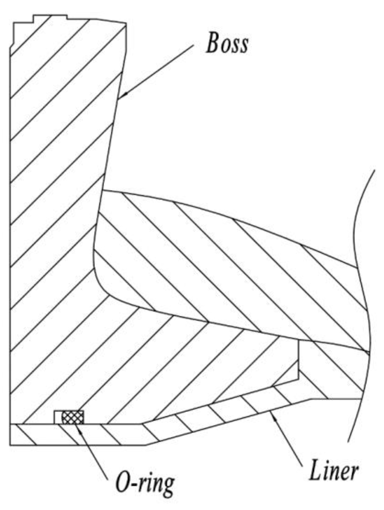
Apart from the connection between the boss and the liner, the sealing structure plays an important role in improving the stiffness and strength of the mouth structure in the composite vessel. In this work, an axisymmetric 2D model (see
Figure 13) was created to simulate the sealing structure between the boss and the liner. The stress changes of the O-ring were analyzed under the initial pressure of 0 MPa and the gradual pressure increase. EPDM rubber was chosen as the material for the O-ring, and the strain energy function of the material is described by the Mooney–Revlin model. The two constants C1 and C2 in this function are 0.782 and 0.071, respectively.
Secondly, the contact between metal and rubber is considered to be direct contact between a flexible body and a rigid body. The penalty function method is used. The contact between the O-ring and the metal is defined as frictional contact, and the coefficient of friction between the O-ring and the metal is set to 0.1. The coefficient of friction between the O-ring and the plastic is set to 0.04 and the coefficient of friction between the plastic inner liner and the boss is set to 0.02. Finally, the load was applied in two steps. In the first step, a displacement load was applied to the opening to compress the seal. In the second step, pressure was applied to calculate the stress state of the seal structure under actual working conditions.
In the analysis of O-ring sealing performance using finite element methods, von Mises stress and contact stress are key parameters studied under various operating conditions. Von Mises stress is utilized to assess the risk of breakage and fatigue failure in O-rings. Typically, higher von Mises stress levels indicate a higher likelihood of O-ring failure due to potential defects, fractures, or damage. A seal structure is deemed effective in maintaining good sealing performance when the contact stress exceeds the medium pressure.
Figure 14 illustrates that peak contact stresses and mises stresses of the O-ring have a linear relationship with the hydrogen pressure. The black color indicates the von Mises stress, while the red color signifies the contact stress. Additionally, the contact stress of the O-ring surpasses the hydrogen pressure within the vessel at varying pressure levels, indicating that the O-ring may play a sealing role in preventing hydrogen leakage during inflation and pressurization.
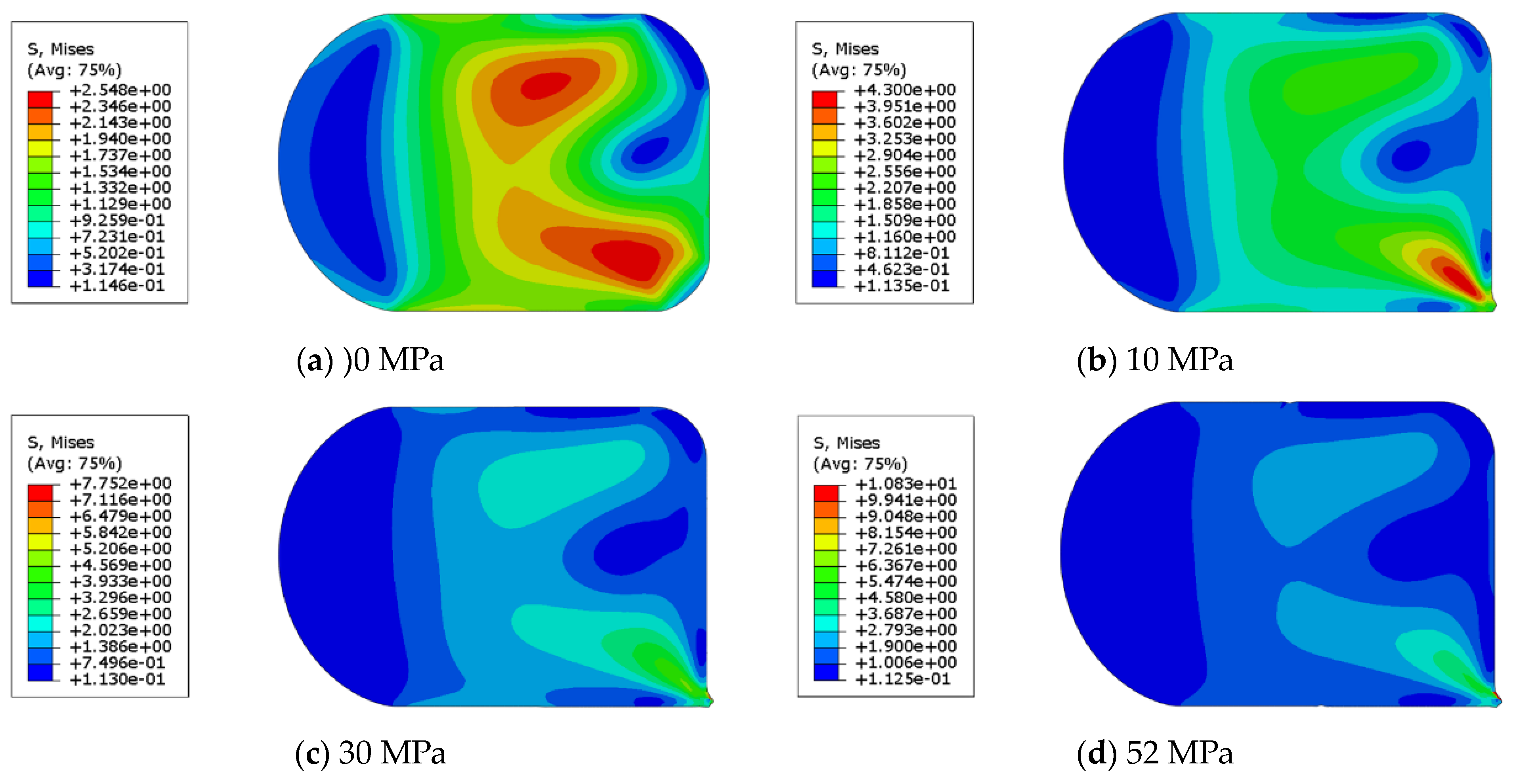
In
Figure 15, it is shown that the maximum stress of the O-ring is at 0 MPa near the plastic liner. With increasing pressure, the O-ring is pushed towards the space between the metal boss and plastic liner, leading to maximum stress in the extrusion zone. Consequently, failure of the O-ring may happen in this region because of stress concentration, resulting in hydrogen leakage from the gap between the plastic liner and the boss.
To improve the sealing performance of the bottle mouth structure, the connection structure between the boss and the inner liner can be improved. The optimization of the sealing performance of the connection structure focuses on reducing the deformation of the O-ring under high pressure so that it is possible to increase the thickness of the inner liner and use a retaining ring together with the O-ring to avoid the occurrence of extrusion of the O-ring under high pressure.
4. Conclusions
A comparative study of the connection between the fiber, the liner, and the boss was also carried out. In the following, some conclusions are drawn from this work:
(1) As the radius of the annular flange increased, the maximum Mises stresses of the carbon fiber, the metallic boss, and the plastic liner initially decreased and then increased. At a radius of 90–100 mm, the peak Mises stresses of all three components are the lowest.
(2) Changing the shape of the contact surface between the neck and the flange of the boss structure resulted in a reduction of the equivalent peak stress in the boss neck region by less than 2%. In addition, the Mises peak stress at the boss flange edge can be reduced by increasing the discontinuity in the contact area between the metallic boss and the carbon fiber.
(3) When examining the effect of the geometry shape of the boss, the change in shape has a much greater effect on the maximum Mises stress of the liner compared to the boss, which shows that more attention should be paid to the opening structure of the plastic liner when designing the liner–boss joint.
(4) The use of a “double lip” structure in the opening design of the liner may lead to a maximum Mises stress of 110 MPa at the contact surface between the boss and the liner, which exceeds the material yield strength of PA6. Therefore, it is better to use a semi-closed structure for the opening of the liner to meet the strength requirements.
(5) When O-rings are in use, the O-ring is pressed into the gap between the metal boss and the plastic liner by the enormous gas pressure, so that it can fail due to the stress concentration and hydrogen escapes from the gap. Therefore, the sealing performance of the boss–liner structure can be optimized by increasing the thickness of the inner liner and using a retaining ring.
