


Sustainable Application of Blast Furnace Slag in the Field of 3D Printing: Material Configuration and Machine Optimization


Abstract
1. Introduction
1.1. Background
1.2. Research Objective and Significance
1.3. Research Content
- (1)
- The potential performance and feasibility of blast furnace slag in 3D printing were analyzed, and effective methods were explored to improve 3D printing performance.
- (2)
- A 3D-printed raw material with hydraulicity was prepared by mixing blast furnace slag with desulfurization gypsum and water, and the performance and characteristics of the mixtures were verified and evaluated.
- (3)
- Three-dimensional printing technologies that match the mixtures were investigated. The printing nozzle, extrusion method, and material reservation of 3D printers were designed and improved, and explicit data support was provided.
2. Feasibility of the Application of Blast Furnace Slag in 3D Printing
2.1. Analysis of 3D Printing Adaptation Technologies for Blast Furnace Slag
2.2. Feasibility Analysis of Preparing 3D Printing Materials Using Blast Furnace Slag
3. Material Analysis and Experiment
3.1. Composition and Harmful Analysis of Blast Furnace Slag Powder
3.2. Experimental Study on the Hydraulicity of Blast Furnace Slag Powder
3.3. Analysis of the Effect of Adding Gypsum and Hydraulicity
4. Exploration of the Optimal Ratio and Characteristics of Mixed Materials
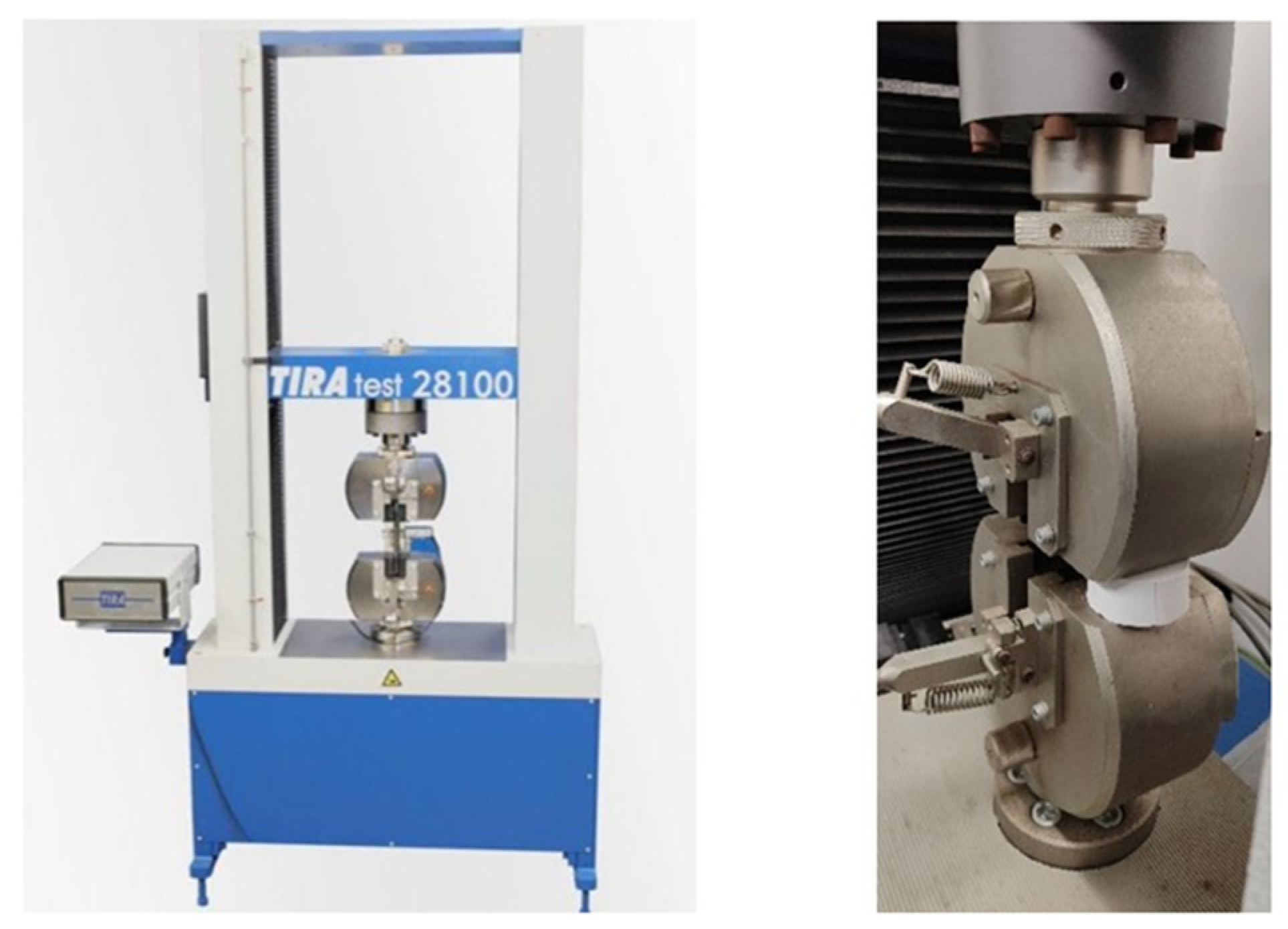
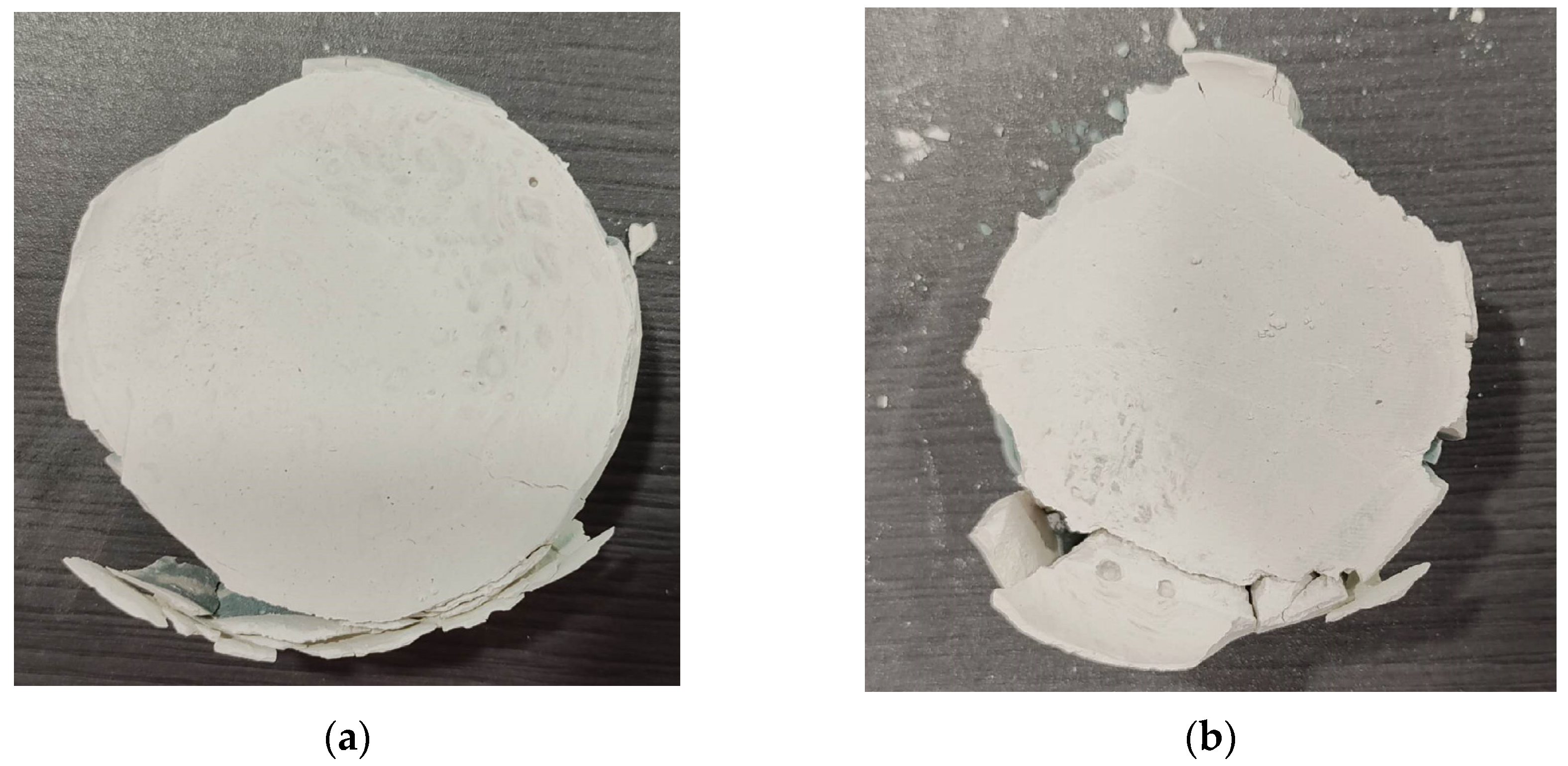
4.1. Experiment on the Optimal Ratio of Mixed Materials
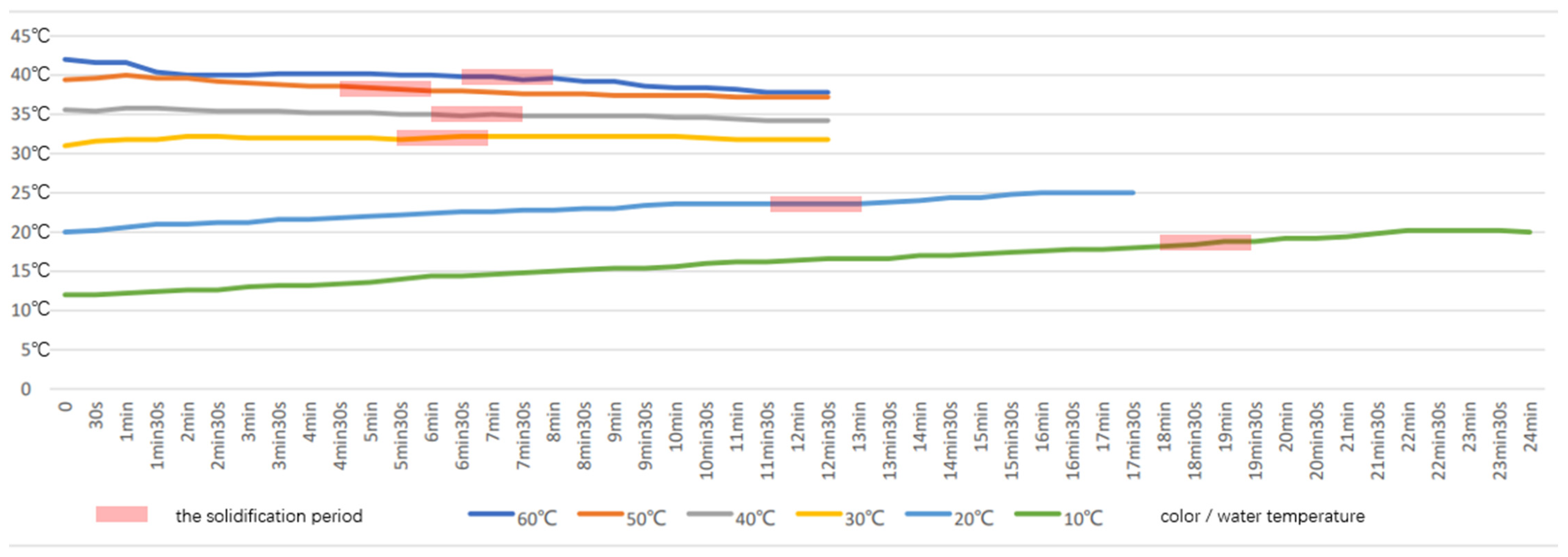
4.2. Verification of the Influence of Water Temperature on Material Solidification Time
5. Improvement of Printing Equipment
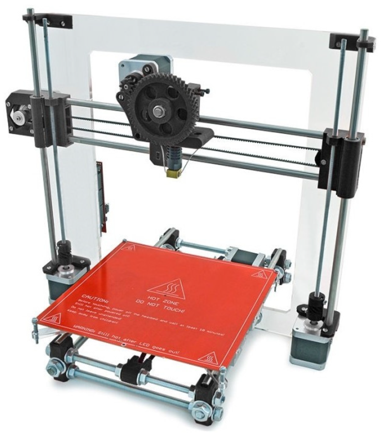
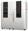
5.1. Printer Selection
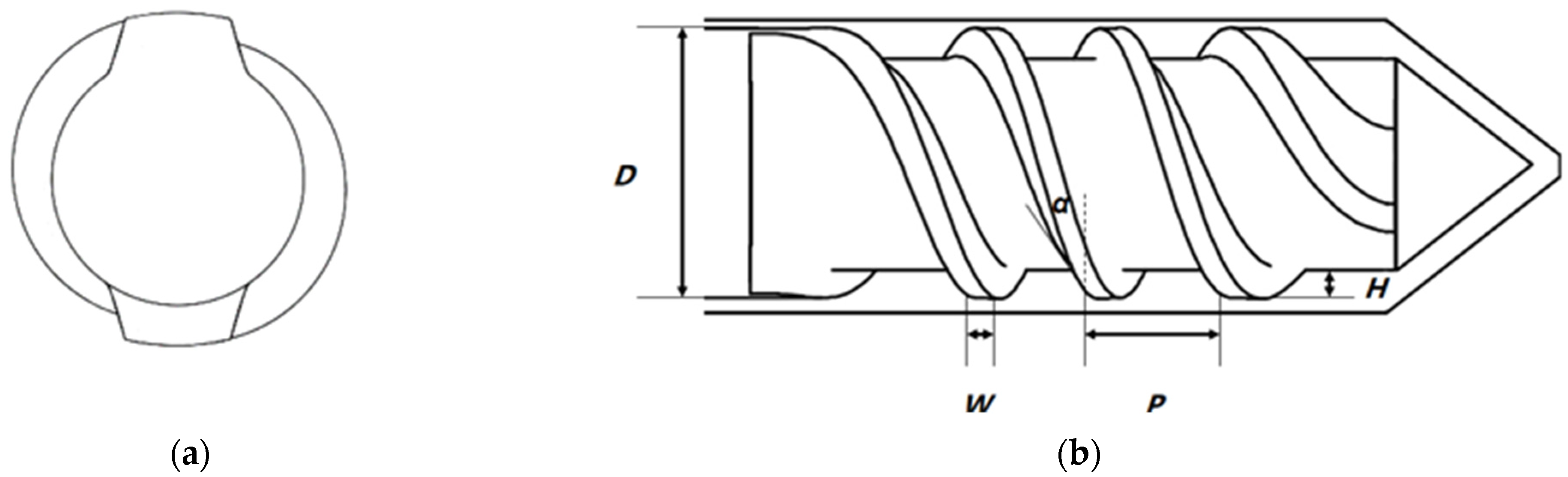
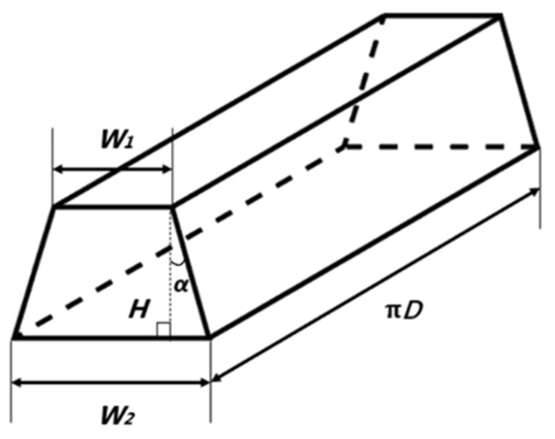
5.2. Improvement in the 3D Printing Nozzle
5.3. Printing Speed of 3D Printers
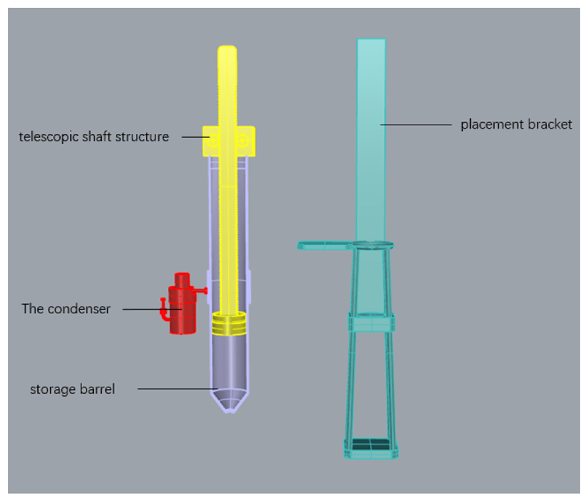
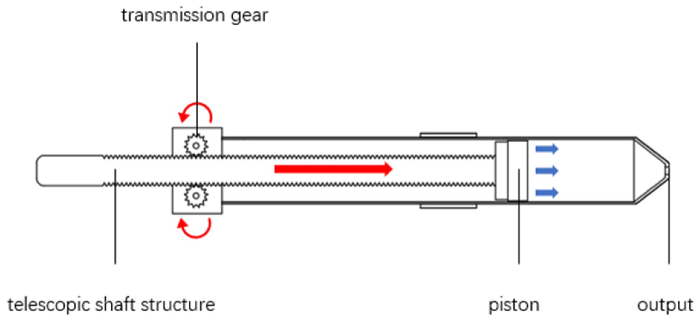
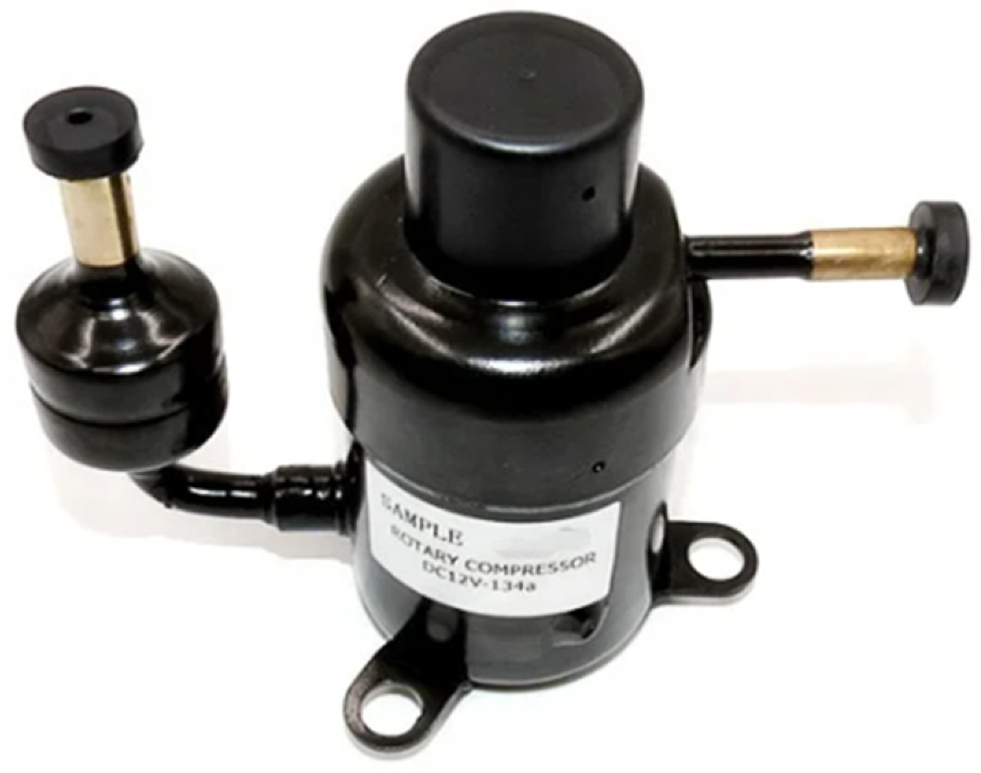
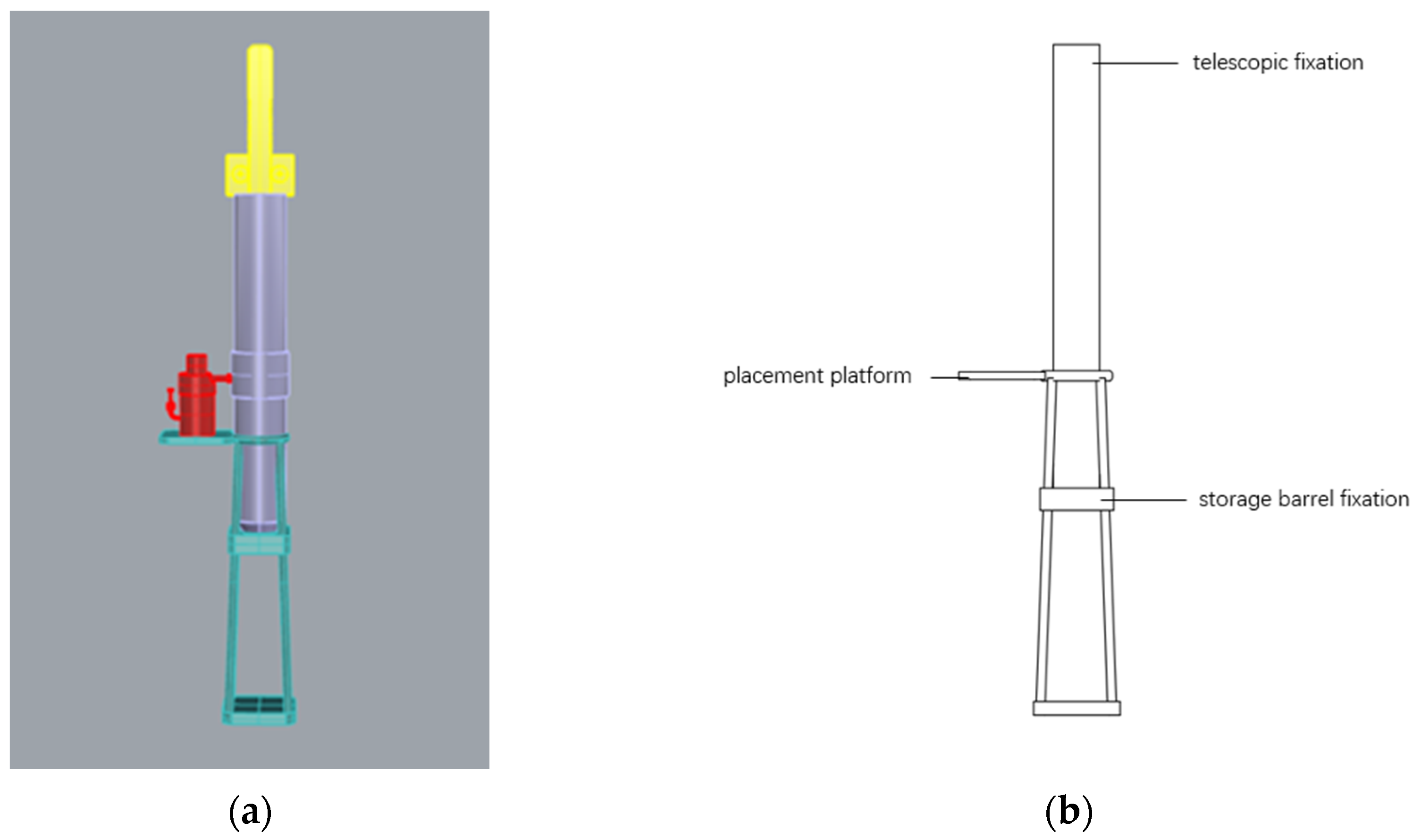
5.4. Design of the 3D Printing Material Reserve Device
6. Summary and Feasibility Analysis
6.1. Summary
6.2. Feasibility Analysis
Author Contributions
Funding
Data Availability Statement
Conflicts of Interest
References
- Yin, R.; Xu, D. Research on Current Situation and Countermeasures of Recycling of Main Solid Waste in Steel Industry; Chinese Academy of Engineering: Beijing, China, 2013; Volume 3. [Google Scholar]
- Zhang, Y.; Xie, L.; Zhang, F.; Zhang, J.; Cao, Y.; Gao, Y. Impact of Adding Fly Ash and Mineral Powder on Mechanical Properties of Coarse Aggregate Full-Substituted Concrete. Concrete. Available online: https://kns.cnki.net/kcms/detail/21.1259.TU.20230505.1514.002.html (accessed on 5 January 2024).
- Gao, Y. Model Decomposition for Multi-Directional FDM 3D Printing. Master’s Thesis, Beijing University of Technology, Beijing, China, 2020. [Google Scholar]
- Liu, B.; Zhang, X. Feasibility analysis of preparing Xuanwu rock wool by melting blast furnace slag. Multipurp. Util. Miner. Resour. 2006, 1, 44–47. [Google Scholar]
- Song, R.; Wang, Y.; Ishutov, S.; Zambrano-Narvaez, G.; Hodder, K.J.; Chalaturnyk, R.J.; Sun, S.; Liu, J.; Gamage, R.P. A Comprehensive Experimental Study on Mechanical Behavior, Microstructure and Transport Properties of 3D-printed Rock Analogs. Rock Mech. Rock Eng. 2020, 53, 5745–5765. [Google Scholar] [CrossRef]
- Leventis, A.; Verganelakis, D.A.; Halse, M.R.; Webber, J.B.; Strange, J.H. Capillary Imbibition and Pore Characterisation in Cement Pastes. Transp. Porous Media 2000, 39, 143–157. [Google Scholar] [CrossRef]
- Duan, C.; Sun, Y. Effect of adding high-performance mineral admixtures on performance of high-strength manufactured sand concrete. Bull. Chin. Ceram. Soc. 2021, 40, 2296–2305. [Google Scholar]
- Wang, J. Study on Activation and Application Performance of Granulated Blast Furnace Slag Gel. Master’s Thesis, Shandong University of Science and Technology, Qingdao, China, 2010. [Google Scholar]
- Shi, H.; Xia, M.; Guo, X. Research progress on reaction mechanism and component effects of fly ash-based polymers. J. Chin. Ceram. Soc. 2013, 41, 972–980. [Google Scholar]
- Wang, X.; Wang, Y.; Yang, L.; Zhu, X. Research on high-performance and high-volume fly ash concrete. Bull. Chin. Ceram. Soc. 2013, 32, 523–532. [Google Scholar]
- Xu, Z.; Jie, Y.; Xu, M.; Ma, J. Study on sintering performance and mechanisms of ultrafine fly ash. Non-Met. Mines 2018, 41, 7–10. [Google Scholar]
- Ma, K.; Long, G.; Xie, Y.; Chen, X. Factors influencing plastic viscosity of cement-fly ash-limestone slurry. J. Chin. Ceram. Soc. 2013, 41, 1481–1486. [Google Scholar]
- Tong, W.; Yao, X.; Mo, W. Analysis of flue gas desulfurization methods and applications of desulfurization gypsum. New Build. Mater. 2006, No. 8, 55–57. [Google Scholar]
- Deng, K. Analysis of current situation of comprehensive utilization technologies of solid waste—Exploring specialization in comprehensive utilization technologies of fly ash, gangue, tailings, desulfurized gypsum, and straw. China Resour. Compr. Util. 2011, 29, 33–42. [Google Scholar]
- Siagi, Z.O.; Mbarawa, M. Dissolution rate of South African calcium—Based materials at constant pH. J. Hazard. Mater. 2009, 16, 678–682. [Google Scholar] [CrossRef] [PubMed]
- Hesse, C.; Goetz-Neunhoeffer, F.; Neubauer, J. A new approach in quantitative in-situ XRD of cement pastes: Correlation of heat flow curves with early hydration reactions. Cem. Concr. Res. 2011, 41, 123–128. [Google Scholar] [CrossRef]
- Zdravkov, B.; Pelovski, Y. Thermal behaviour of gypsum based composites. J. Therm. Anal. Calorim. 2007, 88, 99–102. [Google Scholar] [CrossRef]
- Li, Y.; Wu, B.; Ni, W.; Mou, X. Synergism in early hydration reactions of slag-steel slag-gypsum system. J. Northeast. Univ. (Nat. Sci.) 2020, 41, 581–586. [Google Scholar]
- Song, R.; Liu, J.; Yang, C.; Sun, S. Study on the multiphase heat and mass transfer mechanism in the dissociation of methane hydrate in reconstructed real-shape porous sediments. Energy 2022, 254 (Pt C), 124421. [Google Scholar] [CrossRef]
- Bock, E. On the solubility of anhydrous calcium sulphate and of gypsum in concentrated solutions of sodium chloride at 25 °C, 30 °C, 40 °C, and 50 °C. Can. J. Chem. 1961, 39, 1746–1751. [Google Scholar] [CrossRef]
- Tai, X.; Liu, D.; Zhang, Z.; He, Y. Numerical simulation of flow properties of particles based on 3D-printing screw extrusion device. J. Eng. Thermophys. 2018, 39, 119–124. [Google Scholar]
- Schaffner, M.; Faber, J.A.; Pianegonda, L.; Rühs, P.A.; Coulter, F.; Coulter, A.R. 3D printing of robotic soft actuators with programmable bioinspired architectures. Nat. Commun. 2018, 9, 878. [Google Scholar] [CrossRef] [PubMed]
- Centennial Architecture News: Review of Chinese Slag Powder Market in 2023 and Exhibition in 2024. Available online: https://m.100njz.com/a/24011012/4709BA120A25361A_abc.html (accessed on 10 January 2024).


| 3D Printing Method | Technical Difficulty | Requirement for Printing Environment | Equipment Size and Capital Investment. | Pollution |
|---|---|---|---|---|
 FDM FDM | low | Relatively low, and a regular office environment is sufficient. | Most equipment is small and medium-sized; the investment in small equipment is low. | Almost no pollution. |
 SLA SLA | medium | A relatively clean and enclosed environment is required to avert dust and impurities from entering the liquid-photosensitive resin. | Mostly is small equipment with low investment. | Uncured resin residues and wastewater are generated. The printing environment should be controlled for collection and treatment. |
 SLS SLS | high | A relatively enclosed environment is required to prevent the leakage of powder materials and the entry of impurities. | Usually needs large-scale equipment and investment. | Uncured powder materials are generated. The printing environment should be controlled for collection and treatment. |
 DLP DLP | medium | A relatively enclosed environment is required to inhibit the leakage of photosensitive materials and the entry of impurities. | Usually is medium-sized equipment with moderate investment. | Uncured resin residues and wastewater are generated. The printing environment should be controlled for collection and treatment. |
 Binder Jetting Binder Jetting | medium | A relatively enclosed environment is required to prevent the leakage of powder materials and the entry of impurities. | Mostly is small equipment with low capital investment. | Uncured adhesive residues and wastewater are generated. The printing environment should be controlled for collection and treatment. |
 EBM EBM | high | A vacuum or low-pressure environment is required to ensure the normal operation of the electron beam. | Usually needs large-scale equipment and investment. | Uncured metal powders are generated. The printing environment should be controlled for collection and treatment. |
| Element | Wt% | Wt% Sigma | Atomic % |
|---|---|---|---|
| C | 1.89 | 0.22 | 3.67 |
| O | 34.89 | 0.25 | 50.98 |
| Na | 0.36 | 0.05 | 0.36 |
| Mg | 4.96 | 0.08 | 4.77 |
| Al | 8.58 | 0.10 | 7.44 |
| Si | 16.67 | 0.14 | 13.87 |
| S | 1.01 | 0.06 | 0.74 |
| K | 0.35 | 0.07 | 0.21 |
| Ca | 29.54 | 0.23 | 17.23 |
| Ti | 0.69 | 0.13 | 0.34 |
| Cu | 1.05 | 0.14 | 0.39 |
| Total: | 100.00 | 100.00 |
| Number | Proportions | After 30 s | After 30 min | After 1 h | The Moisture Was Removed | After 22 h |
|---|---|---|---|---|---|---|
| 1 | 1:9 | 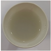 |  |  | 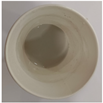 | 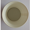 |
| 2 | 2:8 |  | 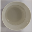 |  |  | 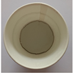 |
| 3 | 3:7 | 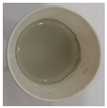 | 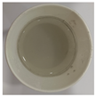 |  | 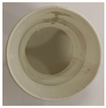 | 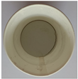 |
| 4 | 4:6 | 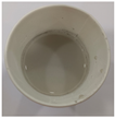 |  | 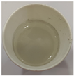 |  | 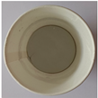 |
| 5 | 5:5 | 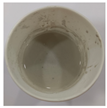 | 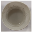 | 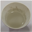 |  | 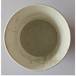 |
| 6 | 6:4 | 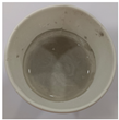 | 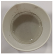 | 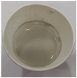 | 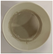 | 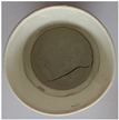 |
| 7 | 7:3 | 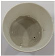 |  | 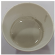 | 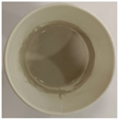 | 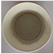 |
| 8 | 8:2 |  | ||||
| 9 | 9:1 | 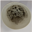 |
| Number | Ratio of Slag Powder to Water | Material Strength (N) |
|---|---|---|
| 1 | 1:9 | 5 |
| 2 | 2:8 | 8 |
| 3 | 3:7 | 17.3 |
| 4 | 4:6 | 26.5 |
| 5 | 5:5 | 41 |
| 6 | 6:4 | 68.2 |
| 7 | 7:3 | 91.3 |
| Number | Proportion of Blast Furnace Slag Powder (g) | Proportion of Desulfurized Gypsum (g) | Proportion of Water (g) | Material Strength (N) |
|---|---|---|---|---|
| 1 | 60 | 30 | 34 | 87,000 |
| 2 | 60 | 45 | 37 | 37,900 |
| 3 | 60 | 60 | 40 | 92,500 |
| 4 | 75 | 30 | 37 | 84,200 |
| 5 | 75 | 45 | 40 | above 100,000 |
| 6 | 75 | 60 | 34 | 97,500 |
| 7 | 90 | 30 | 40 | above 100,000 |
| 8 | 90 | 45 | 34 | 60,000 |
| 9 | 90 | 60 | 37 | 78,000 |
Disclaimer/Publisher’s Note: The statements, opinions and data contained in all publications are solely those of the individual author(s) and contributor(s) and not of MDPI and/or the editor(s). MDPI and/or the editor(s) disclaim responsibility for any injury to people or property resulting from any ideas, methods, instructions or products referred to in the content. |
© 2024 by the authors. Licensee MDPI, Basel, Switzerland. This article is an open access article distributed under the terms and conditions of the Creative Commons Attribution (CC BY) license (https://creativecommons.org/licenses/by/4.0/).
Share and Cite
Li, D.; Cui, X.; Jang, J.-s.; Wang, G. Sustainable Application of Blast Furnace Slag in the Field of 3D Printing: Material Configuration and Machine Optimization. Sustainability 2024, 16, 4058. https://doi.org/10.3390/su16104058
Li D, Cui X, Jang J-s, Wang G. Sustainable Application of Blast Furnace Slag in the Field of 3D Printing: Material Configuration and Machine Optimization. Sustainability. 2024; 16(10):4058. https://doi.org/10.3390/su16104058
Chicago/Turabian StyleLi, Dongsheng, Xinyun Cui, Jung-sik Jang, and Guoxian Wang. 2024. "Sustainable Application of Blast Furnace Slag in the Field of 3D Printing: Material Configuration and Machine Optimization" Sustainability 16, no. 10: 4058. https://doi.org/10.3390/su16104058
APA StyleLi, D., Cui, X., Jang, J.-s., & Wang, G. (2024). Sustainable Application of Blast Furnace Slag in the Field of 3D Printing: Material Configuration and Machine Optimization. Sustainability, 16(10), 4058. https://doi.org/10.3390/su16104058