Article

Economic Analysis of Gas Turbine Using to Increase Efficiency of the Organic Rankine Cycle

by
Dominika Matuszewska
Department of Thermal and Fluid Flow Machines, Faculty of Energy and Fuels, AGH University of Science and Technology, 30 Mickiewicza Ave., 30-059 Cracow, Poland
Sustainability 2024, 16(1), 75; https://doi.org/10.3390/su16010075
Submission received: 21 August 2023 / Revised: 11 November 2023 / Accepted: 30 November 2023 / Published: 21 December 2023
(This article belongs to the Special Issue Safety and Reliability of Renewable Energy Systems for Sustainability)

Abstract

:
In this research, a modified organic Rankine cycle (ORC) system has been presented and examined. This system incorporates a gas turbine as an additional subsystem to boost the enthalpy of geothermal brine. The primary objective of this study is to perform an economic evaluation of the modified ORC system, wherein a gas turbine is utilized to enhance the quality of geothermal steam. The suggested modified ORC system is particularly well-suited for areas abundant in geothermal resources with low to medium temperatures. It offers a more effective utilization of such resources, resulting in improved efficiency. The study considered 10 different working fluids and 8 types of gas turbines used to heat the geothermal water brine witch, the temperature vary of which varies between 80–130 °C. Various flue gas temperatures behind the heat exchanger, as well as temperatures of the return of the geothermal water to the injection hole, were examined. Based on that, 990 variations of configuration have been analyzed. The research showed that the lowest simple payback time (SPBT) values were achieved for the SGT-800 gas turbine and the working fluid R1336mzz(Z), for example, for an electricity price equal 200 USD/MWh and a natural gas price equal to 0.4 USD/hg, resulting in a SPBT value of 1.45 years. Additionally, for this variant, the dependence of SPBT on the price of electricity and the depth of the geothermal well was calculated; assuming the depth of the geothermal well is 2000 m, SPBT changes depending on the adopted gas prices and so for 150 USD/MWh it is 2.2 years, while at the price of 100 USD/MWh it is 5.5 years. It can be concluded that a decrease in SPBT is observed with an increase in the price of electricity and a decrease in the depth of the geothermal well. The findings of this study can help us to better understand the need to utilize low and medium temperature geothermal heat by using combined cycles (including gas turbines), also from an economic point of view.

1. Introduction

Energy has become a fundamental element crucial for the progress of nations and a vital commodity necessary for economic advancement. Over the past few years, there has been a noticeable surge in the need for electric power, accompanied by associated challenges [1,2]. The rising consciousness regarding the impact of energy on global warming, depletion of the ozone layer, and the environment, coupled with escalating prices, has led to an increasing adoption of waste heat and renewable energy sources for electricity generation [3,4]. In addition, activities and research are being undertaken to apply solutions in the area of energy storage [5,6].
The organic Rankine cycle (ORC) is recognized as a prominent technology for harnessing low-temperature heat sources. The appeal of the ORC lies in its straightforwardness, dependability, and adaptability, stemming from its ability to effectively utilize waste heat from renewable sources, such as solar energy [7,8,9,10], geothermal energy [11,12,13,14], biomass [15,16,17,18], and waste heat processes [19,20,21,22].
Geothermal energy serves as a dependable and widely employed alternative energy source in the electricity production sector worldwide. However, its utilization is predominantly constrained by the temperature and mass flow of geothermal water obtained from production wells. Notably, unlike other renewable sources, geothermal energy remains unaffected by seasonal, climatic, and geographical conditions [23]. Converting geothermal energy into electricity plays a pivotal role in conserving energy resources. Nonetheless, the power output of such systems is directly contingent upon the steam parameters entering the turbine, including the quality of the geothermal brine utilized. While high-temperature geothermal resources pose no hindrance to efficient electricity production, employing sources with lower parameters can be more difficult. Currently, the most effective approach to harnessing low-temperature heat sources is through binary power plants [24]. Organic Rankine cycle (ORC) technology is well-established and mature for medium- and large-scale power plants. However, the scenario changes when dealing with small-scale ORC systems, as they present numerous challenges concerning system layout, working fluid selection, and expander design, necessitating careful consideration considering specific conditions [23,25].
Numerous research studies in the field of organic Rankine cycle (ORC) technology have focused on working fluid selection, as it plays a crucial role in optimizing resource utilization. Hung et al. [26] conducted a study on various working fluid candidates and highlighted the significant impact of the shape of the saturated vapor curve on ORC system design and performance. Chen et al. [27] investigated 35 wet, isentropic, and dry working fluids for ORCs and supercritical Rankine cycles. Their findings demonstrated that the selection of working fluid strongly influences cycle performance, with isentropic and dry fluids proving most suitable for ORC cycles. Saleh et al. [28] examined 31 pure fluids from different chemical classifications (alkanes, fluorinate alkanes, ethers, and fluorinate ethers) suitable for low-temperature geothermal resources. They analyzed both subcritical and supercritical processes, with a temperature limitation of 100 °C. The study also provided recommendations for incorporating an internal heat exchanger in cases where the vapor leaving the turbine is superheated. Quoilin et al. [29] demonstrated that different objective functions in thermodynamic and economic optimization lead to varying optimal operating conditions for the same working fluid. Özcan and Ekici [30] proposed a new method for selecting working fluids in organic Rankine cycles (ORCs) combined with low-grade geothermal sources. They used data from an operating binary geothermal plant that uses n-pentane. By considering thermodynamic and thermo-economic factors, they evaluated 29 single-component working fluid candidates from different chemical branches using a four-step elimination method. The results show that the vapor expansion ratio (VER) has a direct relationship with the network output for dry working fluids, while isentropic fluids behave differently from dry fluids. Di Marcoberardino et al. [31] investigated thermal stability of siloxanes and the thermodynamic performance of siloxane mixtures, showing that their efficiencies were comparable to those of pure fluids currently in use. Liu et al. [32] investigated hydrofluoroolefins (HFOs) as novel working fluids specifically designed for ORC systems, aiming to replace traditional refrigerants due to their positive environmental impact (zero ozone depletion potential and very low global warming potential). They found that some of the investigated HFOs exhibited promising system efficiency, particularly for low and medium temperature geothermal ORC power generation. Matuszewska et al. [33] identified a region of low stability in dense vapors within dry and isentropic ORC fluids. This leads to peculiarities in fluid behavior concerning thermodynamic parameters and compressible flow conditions, which must be considered during working fluid selection and expander design processes. Wang et al. [34] demonstrated that the thermal stability of working fluids plays a crucial role in determining the choice of fluid and designing ORC systems. In their investigation, they developed an off-design model of an ORC system utilizing hexamethyldisiloxane (MM) as the working fluid and conducted an analysis on the impacts of MM’s thermal stability on the system.
The organic Rankine cycle (ORC) has proven to be effective in recovering waste heat from exhaust gases generated by engines, turbines, and industrial processes [35,36,37,38]. Given that approximately 30% of the chemical energy in fuel is lost through exhaust gases, there is significant potential for the useful recovery of this waste heat [39]. In many cases, the ORC is commonly employed as a bottoming cycle to utilize the waste heat from gas turbines [40,41,42,43,44].
However, most of the energy input in a typical geothermal power plant is wasted as heat rather than being converted into electricity. The temperature of vapor obtained from geothermal brine is relatively low, so it would be advantageous to heat it before expanding it in a steam turbine. This approach could significantly enhance the thermal efficiency of the geothermal power plant. Bidini et al. [45] demonstrated that by heating the geothermal steam, its quality improved, leading to enhanced performance of the conventional geothermal power plant. Astina et al. [46] took this concept further by optimizing various parameters of the geothermal system. They proposed a hybrid system to upgrade the geothermal power plant, which involved integrating it with a gas turbine, refrigeration heat pumps, and an organic Rankine cycle. As a result, the system efficiency increased significantly from 19.85% to 35.8%. Both studies indicate the potential for improving geothermal power plants by connecting them with conventional (fossil fuel) power plants. The next sections will present a more comprehensive discussion on utilizing geothermal heat for power generation, focusing on a modified ORC system.
In the literature, one can find numerous studies concerning ORC systems (as shown above), gas turbine systems, and methods of improving their efficiency [47], or on the phenomenon of heat transfer [48]. However, there has been limited research conducted on the topic of elevating the temperature of geothermal brine prior to its entry into the binary power plant.
Typically, the gas turbine and ORC (GT-ORC) combined cycle is divided into two subsystems—the topping gas turbine system and the bottoming organic Rankine cycle system. To recover exhaust heat from the topping gas turbine, the bottoming ORC system is used [49]. In the proposed system, the exhaust gas heat from the gas turbine is used to increase the temperature of geothermal water obtained from drilling wells in areas where the parameters of heat from geothermal water could be insufficient for utilization in ORC systems. Such use of a gas turbine means that heat to the ORC system is supplied from two sources: geothermal heat and a gas turbine (in cases where this heat could otherwise not be used). In previous analysis conducted by Matuszewska and Olczak [50], a modified organic Rankine cycle (ORC) system was introduced with model and thermodynamic performance analysis. In this system, a gas turbine was incorporated as a supplementary subsystem to enhance the enthalpy of geothermal brine.
The aim of the analyses was to provide information on the possibility of using low- and medium-temperature geothermal heat (in combined systems). In the European Union, there is a strong commitment to developing renewable energy sources, which results in a growing interest in energy sources independent of weather conditions. Although wind turbines and photovoltaics are very popular in the EU, as weather-dependent sources they can lead to a problematic effect known as the “duck curve” in various countries [51]. For this reason, there is a growing interest in alternative sources, such as geothermal energy. However, not all countries have sufficient resources, for example because geothermal water temperatures are too low, which creates challenges. The proposed system may solve this problem, but it is important to analyze its thermodynamic and economic properties in order to examine the possibility of implementing such an approach and solution on the market.
The article presents an innovative approach consisting of the analysis and modeling of a modified organic Rankine cycle (ORC) system, which includes a gas turbine as an additional subsystem increasing the enthalpy of geothermal brine from an economic perspective. The innovation and novelty of this study are the proposal of a modified ORC system and the analysis of its application from an economic perspective regarding the possibility of return on investment depending on various factors that have a significant impact on costs (including electricity prices and natural gas). The analysis was made considering different sizes of gas turbines used and various factors dedicated to ORC systems (factors were selected based on their low global warming potential and ozone depletion potential and or frequency of occurrence in ORC systems analyzed in the literature). The paper is organized as follows. Section 2 of this paper provides a comprehensive description of the model for the modified organic Rankine cycle (ORC) system with thermodynamic and economic analysis. It includes the main equations used, the methodology employed, and the assumptions made during the modeling process. Moving on to Section 3, a summary of the results and discussions pertaining to the system modifications are presented. Finally, in Section 4, the paper concludes with key findings and overall conclusions derived from the study.

2. System Configuration and Modeling

This section shows the configuration of the ORC system, using low- and medium-temperature heat, which is intended to increase the efficiency of the entire system. In the proposed configuration, a gas turbine was used to increase the enthalpy of low- or medium-temperature geothermal heat (the use of which in other conditions might not be feasible or economical) to generate electricity (see Figure 1).
An elementary part of the analyzed system is an ORC system with an organic fluid, characterized by a low-boiling point, as the working medium. The ORC part of installation consists of a heater (where the working fluid is heated), an evaporator (where fluid is evaporated), a turbine which drive a generator of electricity, a condenser, and a pump. The heat transferred to the ORC part of installation is both from geothermal water and exhausted gases from gas turbine. The gas turbine was modeled here as a black box whose exhaust gas heat output parameters were taken for further thermodynamic analysis.
The analysis was carried out, taking into account the various ranges of some parameters, e.g., inlet temperature of geothermal brine, temperature of flue gas after heat exchange, and temperature of geothermal brine pumped to the reinjection well. It was assumed that the geothermal brine inflow temperature ranged from 80 to 130 °C with steps of 5 degrees, while the temperature of geothermal brine pumped to the reinjection well ranged from 60 to 70 °C with steps of 5 degrees. The temperature ranges of these parameters have been chosen because the proposed modified ORC system is dedicated to low- and medium-temperature geothermal heat sources in case of inlet temperature selection [13]. Determining the optimal strategy for reinjection of geothermal systems is a very complex task, and its effectiveness largely depends on the specific properties of the geothermal system under consideration (e.g., various minerals soluble in geothermal fluids). Typically, minimum re-injection temperatures range from 60 °C to 80 °C [52,53]. Due to the inlet temperature, the range of 60–70 °C was selected in the analyzed case. The geothermal brine (with mass flow equal to 100 kg/s) is heated by the flue gas from the gas turbine, whose temperature drops to 240–250 °C (with an interval of 5). The data from eight different gas turbines has been analyzed. The main parameters of those turbines are shown in Table 1.
The ORC cycle itself works based on a low-boiling organic ranking fluid. For that purpose, ten working fluids (F) have been selected, namely R600a, R134a, R152a, R227ea, R245fa, R1224yd(Z), R1233yd(E), R1234yf, R1243zf, and R1336mzzZ. Table 2 shows the properties of the selected ORC working fluid used in this study.
In addition, other parameters of the model have been assumed. One of them is condensation temperature, which is crucial in terms of ORC cycle heat flow calculations. In this study, 25 °C has been chosen as the condensation temperature. The second one is the pressure of evaporation, based on which evaporation temperature can be determined. The evaporation parameters are closely related to the inlet temperature of geothermal brine and the selected heat exchanger’s characteristics. It has been assumed that the pinch point temperature is equal to 5 K.
The efficiency levels of the various devices have been considered at different values in this analysis. The internal turbine efficiency is assumed to be 85%, indicating the effectiveness of converting the energy of the working fluid into mechanical power. The internal pump efficiency is estimated at 65%, representing the efficiency of the pump in transferring the working fluid. Furthermore, the mechanical efficiency of the turbine, which reflects the conversion of mechanical power into electrical power, is assumed to be 97%. Lastly, the generator efficiency is taken to be 97%, indicating the effectiveness of converting mechanical power into electrical power by the generator [50].

2.1. Energy Analysis

The calculations for the energy balance of the modified ORC system were based on fundamental equations, which are provided below. Additionally, the essential parameters that will be examined are also listed. The analysis began by determining the evaporation and condensation temperatures of the working fluid within the ORC power plant. The state parameters of the working fluid at specific points in the ORC cycle were determined using the REFPROP Version 10 software developed by NIST [55]. The subsequent steps followed the following procedure [58]:
  • The specific enthalpy (h1) and specific entropy (s1) were calculated using the evaporation pressure of dry saturated steam (with a quality of x = 1).
  • Considering the isentropic expansion of the vaporized working fluid in the turbine, the specific enthalpy (h2s) was determined based on the specific entropy (s1) and the condensing pressure.
  • The specific enthalpy (h3) was determined using the condensation pressure for dry saturated steam (with a quality of x = 1).
  • The specific enthalpy (h4) was determined based on the condensing pressure for the liquid state, specifically on the saturation line (with a quality of x = 0).
  • Considering the isentropic compression of the working fluid in the pump (s4 = s5) based on specific entropy s4 and evaporation pressure, specific enthalpy h5s was determined.
  • The specific enthalpy (h6) was determined based on the evaporation pressure for the liquid state, specifically on the boundary line.
Equations (1) and (2) can be employed to calculate the real parameters corresponding to points 2 and 5, taking into account the internal efficiencies of the turbine and pump, respectively. Equation (1) is as follows:
η i T = h 1 h 2 r h 1 h 2 s
where the value h1 − h2r denotes the real decline in enthalpy when experiencing an identical pressure drop as encountered during an isentropic transformation. Equation (2) is as follows:
η i T = h 5 s h 4 h 5 r h 4
where the value h5r − h4 denotes the real decline in enthalpy when experiencing an identical pressure drop as encountered during an isentropic transformation.
Equally crucial in the computations was the assessment of the output characteristics of the geothermal brine, specifically, the mass flow rate ( m ˙ G E O ) and its temperature ( T I N ).
The following Equation (3) can succinctly depict the heat exchange balance between the geothermal brine and the exhaust gases of the gas turbine:
Q ˙ S P = m ˙ S P · c S P · T S P 1 T S P 2 = m ˙ G E O · c G E O · T G E O _ A T G E O _ I N
Through the manipulation of the aforementioned equation, it becomes feasible to compute the temperature ( T A ) at which the geothermal brine is provided to the evaporator within the ORC power plant. This specific temperature is attained because of the heating by the exhaust gas stream from the gas turbine system), as follows:
T G E O A = T G E O I N + m ˙ S P · c S P · T S P 1 T S P 2 m ˙ G E O · c G E O
The interaction of heat between the geothermal brine and the organic working fluid takes place within both the evaporator and the preheater. The energy balance equations governing this process in the evaporator are represented by the following relationships, as shown in Equation (5a,b):
Q ˙ E = m ˙ G E O · h A h B = m ˙ O R C · h 1 h 6
Q ˙ E = m ˙ G E O · c G E O · T A T B = m ˙ O R C · h 1 h 6
Preheater energy balance equations can be analyzing using the following equations, namely Equation (6a,b):
Q ˙ P H = m ˙ G E O · h B h C = m ˙ O R C · h 6 h 5 r
Q ˙ P H = m ˙ G E O · c G E O · T B T C = m ˙ O R C · h 6 h 5 r
By employing the balance equations provided above, it becomes feasible to determine the mass flow rate of the ORC fluid, as in the following Equation (7):
m ˙ O R C = m ˙ G E O · c G E O · T G E O _ A T G E O _ C h 1 h 5 r
By determining the specific parameters, such as temperature, enthalpy, pressure, and mass flow rate at distinct characteristic points within the designed installation, it becomes possible to calculate key values that ultimately determine the efficiency of the said installation. This comprehensive analysis of individual parameters provides valuable insights into the performance and effectiveness of the designed system, including the following:
  • ORC efficiency:
η O R C = h 1 h 2 r h 5 r h 4 h 1 h 5 r
  • Power of the ORC cycle:
N O R C = m ˙ G E O · [ h 1 h 2 r h 5 r h 4 ]
  • Electrical power of the designed ORC power plant:
N e l _ O R C = η m · η g · N O R C
where ηm is the mechanical efficiency of the turbine, while ηg is the generator efficiency.
The total electrical power output of the modified ORC installation can be calculated by summing the electric power generated by the ORC power plant with that of the gas turbine system, as denoted by the following Equation (11):
N c o m _ c y c l e = N e l _ O R C + N e l _ T G
where N e l _ T G is the electric power of the gas turbine.
The overall efficiency of the proposed system is characterized by the combined electrical power output divided by the energy supplied to the system through geothermal heat flux and the additional heat flux added to the gas turbine system, as follows:
η O R C = N c o m _ c y c l e Q ˙ T G + Q ˙ G E O
where Q ˙ T G je is the heat flow addition to the gas turbine part, while Q ˙ G E O is the geothermal heat flux.

2.2. Economic Analysis

To effectively evaluate the designed ORC systems using various working fluids under optimal operating conditions, it is crucial to conduct an economic analysis of these systems. Consequently, a comprehensive assessment of the overall costs of the ORC system becomes necessary, involving the calculation of investment costs associated with each individual component. The equations for investment cost (Z) (expressed in USD) of individual devices within the ORC are presented as follows:
  • ORC pump [59]:
Z P = 3540 · W ˙ P 0.7
  • ORC preheater [60]:
Z P H = 2681 · A P H 0.59
  • ORC evaporator [61]:
Z E = 216.6 + 353.4 · A E
  • ORC turbine [60]:
Z T = 4405 · W ˙ g r o s s 0.89
  • ORC Condenser [62]:
Z C = 338.6 · A C
The investment cost of heat exchange between the gas turbine and geothermal brine is calculated based on the following equation:
Z H X = 130 · A H X 0.093 0.78
In the process of cost analysis for heat exchanging equipment, it is essential to compute the heat transfer area. The heat transfer area of such equipment can be determined by employing the following equation [59]:
A = Q ˙ U · T m
where Q ˙ is the heat transferred and U is the overall heat transfer coefficient. T m is the log mean temperature difference, which can be found using the following equation:
T m = T m a x T m i n l n T m a x T m i n
where the terms ΔTmax and ΔTmin represent the highest and lowest temperature differences observed within the heat exchanging equipment, respectively. The values of the heat transfer coefficient U in a heat exchanging system typically rely on factors, such as the material employed and the phase of the flowing heat. For the purposes of this study, it has been assumed that the U values remain constant, as shown in Table 3:
The system maintenance and operation costs of the ORC unit (with a heat exchanger between the gas turbine and geothermal water) have been assumed as 1.5% of the total investment costs [63]. The investment costs for the gas turbine were assumed at 1175 USD/kW. Fixed operation and maintenance (fixOM) costs have been estimated at 16.00 USD/kW/yr. while variable O&M (varOM) are estimated at 4.70 USD/MWh. Planned gas turbine maintenance costs of 18,500 USD per overhaul are assumed as taking place three times a year. [65,66].
The cost of a geothermal well (expressed in millions of dollars) was estimated based on the following equation:
G e o t h e r m a l   w e l l   c o s t :   G W C ( M D ) = 1.72 × 10 7 × M D 2 + 2.3 × 10 3 × M D 0.62
where MD is the depth of the geothermal well, measured in m [67]. The depth of the well has been assumed to be 2000 m (meaning 4.668 mln USD for one geothermal well).
The estimated operational duration for the suggested installation was derived from the average operating hours of geothermal power plants and totaled 7446 h per year [68].
The variations in working fluids and turbines were examined in terms of solution economics [69], considering the simple payback time (SPBT) using the following equation:
S P B T ( G T ,   F ,   C o n f ) = I O ( G T , F , C o n f ) C F ( G T , F , C o n f )
where:
  • IO—investment expenditure, USD;
  • CF—yearly cash flow, USD/year;
  • GT—gas turbine;
  • F—working fluid;
  • Conf—configuration.
Considered configuration (Conf):
  • TSP2 = (240, 245, 250) °C;
  • Tgeo_in = (80–130) °C;
  • TC = (60, 65, 70) °C.
Yearly cash flow (CF) was calculated using the following equation:
C F G T ,   F ,   C o n f = I n c G T , F , C o n f O C o s t G T ,   F , C o n f
where:
  • Inc—operational income, USD;
  • OCost—operational cost, USD.
Operational income was calculated using the following equation:
I n c G T , F , C o n f = n h o u r × p e l × N c o m _ c y c l e ( G T , F , C o n f )
where:
  • pel—electricity price, USD/MWh;
  • nhour—operational number of hours in year: 7446 h;
Operational cost was calculated using the following equation:
O C o s t G T = 3600 × n h o u r × m f u e l ( G T ) × p n g + v a r O M ( G T ) + f i x O M ( G T )
where:
  • png—natural gas price, USD/kg;
  • varOM—variable operation and maintenance cost, USD;
  • fixOM—fixed operation and maintenance cost, USD.
The examined price range for pel is from 50 to 200 USD/MWh. The natural gas price is calculated per kg, with a range of png from 0.2 to 0.6 USD/kg.
Investment expenditures were calculated using the following formula:
I O G T ,   F ,   C o n f = N e l _ T G ( T G ) × p T G + Z o r c + p H E
where:
  • pTG—gas turbine price, USD/kW;
  • pHE—heat exchanger price, USD.

3. Results

The aim of the study was to estimate the SPBT values for different turbine, working fluid, and configuration variants, including parameters, such as geothermal source temperature and exhaust gas temperature. For this purpose, an analysis was conducted based on available data on 8 different types of gas turbines from Table 1, as well as 990 variations in working fluids and configurations.
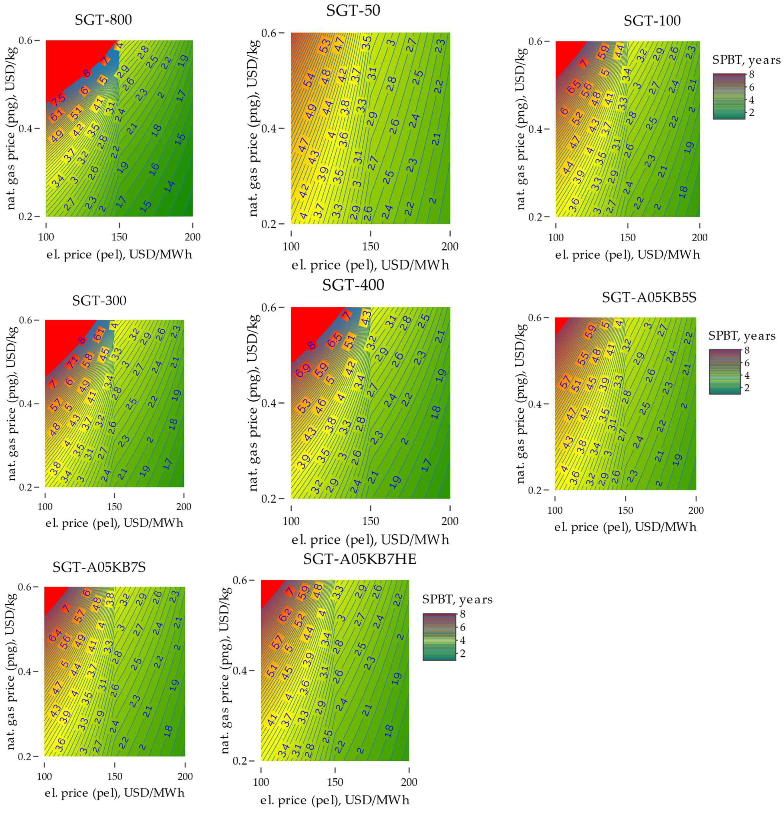
Based on the conducted analysis, results were obtained, and for each gas turbine, a specific configuration and working fluid were determined, resulting in the lowest SPBT values, as shown in Figure 2. Additionally, the results were presented in relation to electricity price and natural gas price.
For all gas turbines, the lowest SPBT values were achieved with the working fluid R1336mzz(Z). The lowest SPBT value was obtained for the SGT-800 turbine; for example, pel = 200 USD/MWh and png = 0.4 USD/kg, resulting in 1.45 years. The highest SPBT value (among the set of lowest values) was calculated for the SGT-50 turbine, with a corresponding value of 2 years.
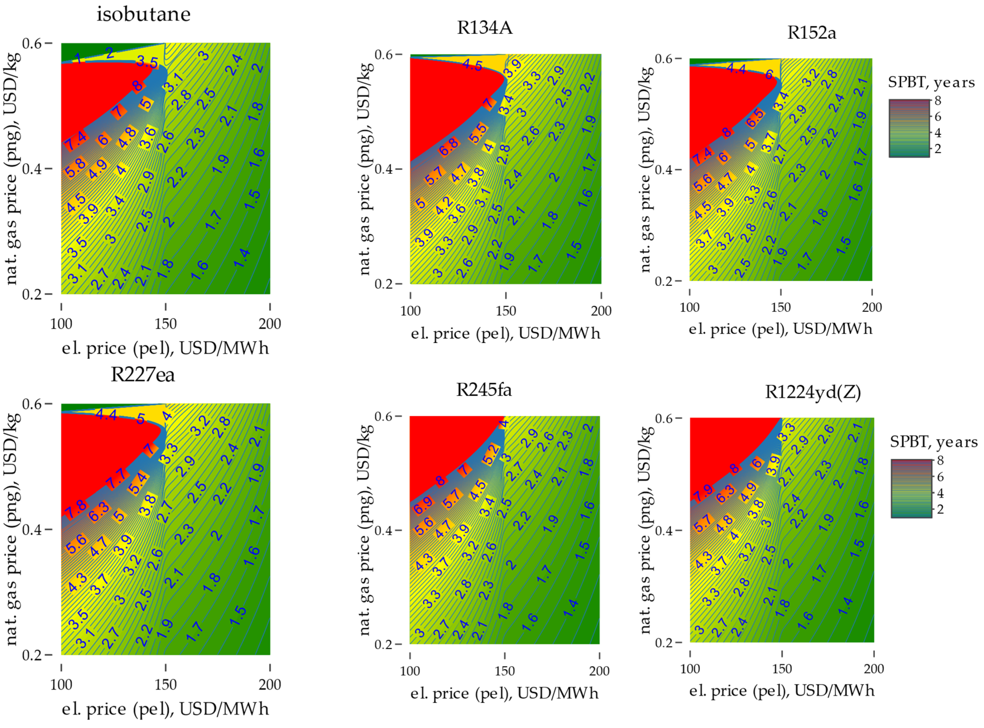
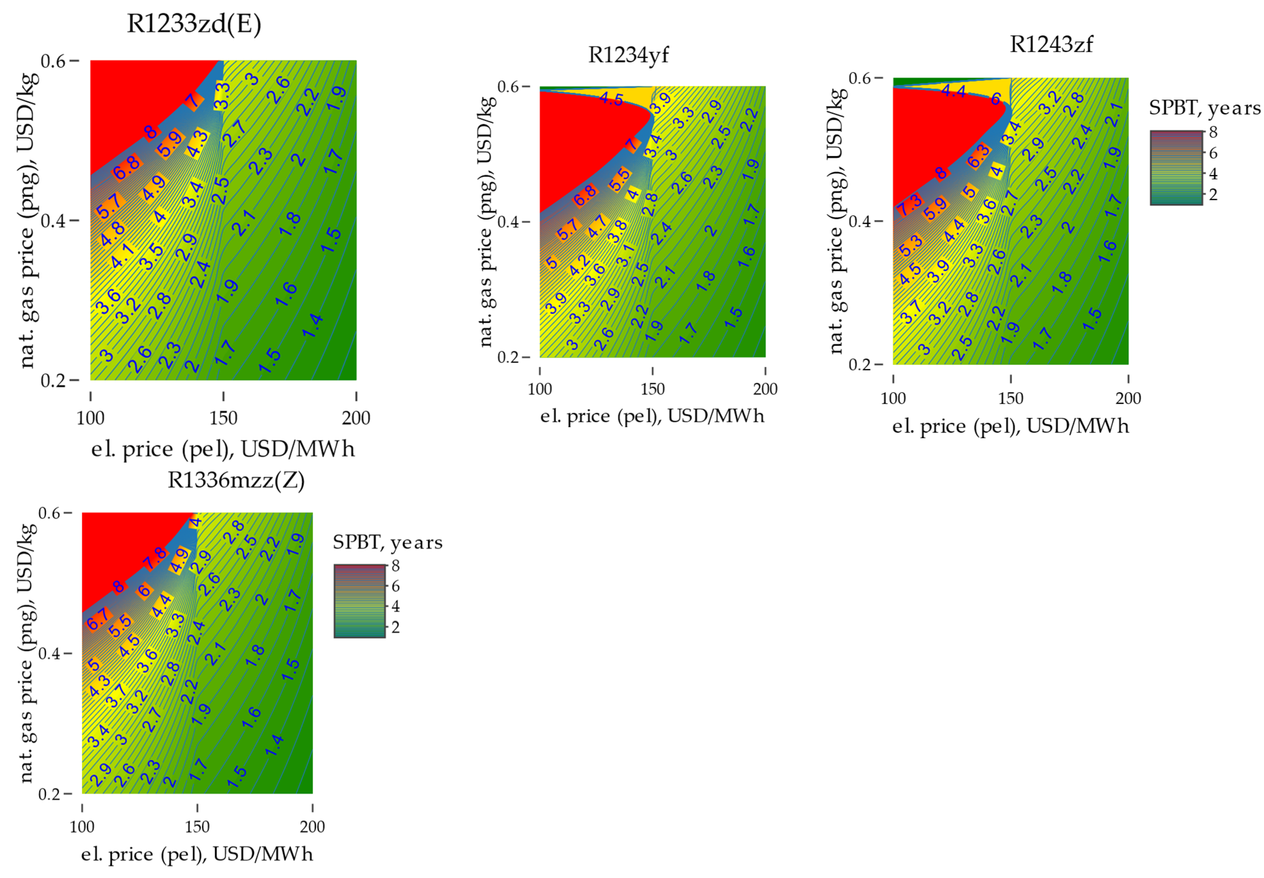
Regarding different working fluids, gas turbines and configurations with the lowest SPBT values were selected, as in Figure 3.
For all of the 10 working fluids that we analyzed, the lowest SPBT values were achieved with the SGT-800 gas turbine. The lowest SPBT value was obtained for the working fluid R1336mzz(Z): pel = 200 USD/MWh and png = 0.4 USD/kg, resulting in 1.45 years. The highest SPBT value (among the set of lowest values) was calculated for R1234yf, yielding a value of 1.6 years.
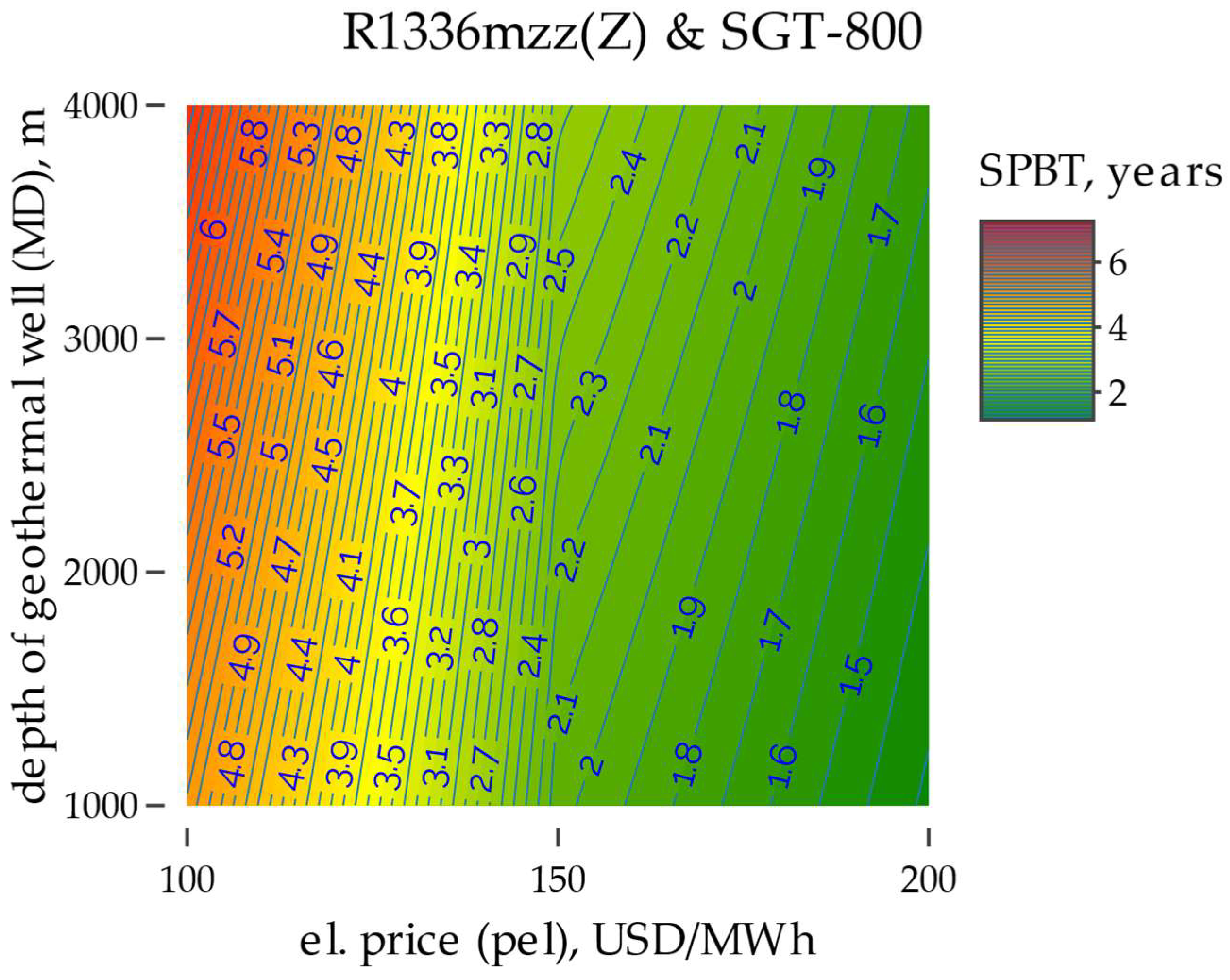
Additionally, the dependence of SPBT on the electricity price and the depth of the geothermal well MD was calculated. This was performed for the working fluid pair and turbine with the lowest SPBT, and the results are shown in Figure 4.

4. Conclusions

Nowadays, we can observe increasing tendencies towards reducing the consumption of fossil fuels for energy purposes, and, thus, reducing the emission of harmful substances into the atmosphere, while reducing the operating costs of the proposed alternative solutions. These factors had a significant impact on the scope of work proposed in this article. Limited access to high-temperature geothermal sources, which in themselves are a stable energy source (compared to wind or solar energy), makes the interest of researchers shift to the use of low- and medium-temperature geothermal energy.
The article proposes an analysis of a modified organic Rankin cycle in which geothermal brine is heated by exhaust gases from a gas turbine.
The analysis was undertaken for a wider range of geothermal water temperatures at the outflow from the production well, i.e., from 80–130 °C. The inlet temperature to the injection well was limited to the range of 60–70 (in steps of 5 degrees) to prevent the hole from overgrowing with substances precipitated from the geothermal water. The combustion temperature of the geothermal water was individually determined for each analyzed type of turbine. On the other hand, the flue gas temperature after the heat exchanger (already after the heat exchanger) was determined at the level of 240–250 °C (in steps of 5 degrees). The analysis considered eight types of gas turbines with different power levels: 2 MWe, 4.0 MWe, 5.1 MWe, 5.4 MWe, 5.8 MWe, 7.9 MWe, 12.9 MWe, and 62.5 MWe. The ORC system itself was modeled as a simple system (without regeneration and superheating). The analysis was carried out for 10 different working fluids with different GWPs: R600a, R134a, R152a, R227ea, R245fa, R1224yd(Z), R1233zd(E), R1234yf, R1243zf, and R1336mzz(Z).
Variations in temperature (inlet and outlet from geothermal wells, exhaust gases downstream of the heat exchanger), the turbine used, and the working fluid were examined in terms of the economics of the solution, considering the simple payback time (SPBT). For this purpose, the costs of individual elements of the solution were determined, depending on the size of the installation and operating parameters, the costs of geothermal and injection wells depending on the depth of drilling, as well as fixed and variable costs considered during the operation of the installation.
Based on the available data, 990 configurations were obtained and analyzed. The results were obtained from the analysis, and for each gas turbine, a specific configuration and working fluid were determined, achieving the lowest SPBT values. Additionally, the results were presented in relation to the electricity price and natural gas price.
For all gas turbines, the lowest SPBT values were achieved using the working fluid R1336mzz(Z). The lowest SPBT value was obtained for the SGT-800 turbine, e.g., with pel = 200 USD/MWh and png = 0.4 USD/kg, resulting in 1.45 years. The highest SPBT value (among the set of lowest values) was calculated for the SGT-50 turbine, with a corresponding value of 2 years.
Due to different working fluids, gas turbines and configurations with the lowest SPBT values were selected. For all of the 10 analyzed working fluids, the lowest SPBT values were achieved for the SGT-800 gas turbine. The lowest SPBT value was obtained for the working fluid R1336mzz(Z): pel = 200 USD/MWh and png = 0.4 USD/kg, resulting in 1.45 years. The highest SPBT value (among the set of lowest values) was calculated for R1234yf, obtaining a value of 1.6 years. Additionally, the dependency of SPBT on the electricity price and geothermal well depth MD was calculated. This was performed for the pair of working fluid and turbine with the lowest SPBT. Given a geothermal well depth of 2000 m, the simple payback time (SPBT) varies based on the chosen gas prices. For instance, at a rate of 150 USD/MWh, the SPBT is 2.2 years, whereas at 100 USD/MWh, it extends to 5.5 years. This suggests that a reduction in SPBT is noticeable with a rise in electricity prices and a decrease in the depth of the geothermal well.
The results showed that both the efficiency and power of the cycle depend on the type of working fluid and gas turbine. However, in the case of organic working fluids, it is important to consider that they operate efficiently within specific temperature and pressure ranges, making proper selection crucial. The combination of a gas turbine system with an ORC power plant yields positive effects by increasing the parameters of the geothermal brine entering the superheater, thereby raising the ORC fluid’s evaporation temperature (which affects the efficiency and power of the ORC cycle). The evaluation of the economic efficiency of such installations indicates that they are worth considering from an economic standpoint. However, it is typically recommended to assess the efficiency of such installations based on additional criteria. Usually, the practicality of its application (with an additional heat source) arises when there is no practical use for waste heat from the turbine (e.g., for technological purposes), but there is a demand for electricity. The limitations of this study were the analysis of only selected working media (the working media were selected due to their low global warming potential and ozone depletion potential or due to the factors most often dedicated to ORC systems), whereas analyzing a larger number of working media could influence the analysis results.
The presented article is part of a broader analysis concerning low-temperature geothermal heat from a thermodynamic, economic, environmental, and socio-legal perspective. The strong focus in the EU on renewable energy sources means that more and more interest is being placed on weather-independent sources (wind turbines and photovoltaics, so popular in the EU, as weather-dependent sources, can deepen the duck curve effect in each country), such as geothermal energy. However, not all countries have access to suitable resources (e.g., due to excessively low temperatures of geothermal waters); therefore, the discussed topic addresses these problems. In Ref. [50], an alternative solution for heating geothermal water with waste heat was proposed (the choice was waste heat from a gas turbine), while the proposed modified organic Rankine cycle itself was analyzed from a thermodynamic point of view, demonstrating the impact of individual factors on the system’s efficiency. Further work planned for the future will involve carrying out an environmental analysis of the proposed solution and discussing (socio-legal) factors that, in a broader context, may contribute to interest in the use of low-temperature geothermal heat. These include legal changes in the EU, the impact of COVID-19, and the effect of the war in Ukraine on electricity prices, as well as the energy stability of the region and its energy dependence. Another planned step in future work is the development of guidelines regarding the conditions (e.g., prices of energy, gas, drilling, stability, availability of energy sources, share of weather-dependent renewable sources in the country’s energy mix, etc.) under which the use of low-temperature heat may be profitable from thermodynamic, economic, environmental, and socio-legal perspectives. Such an analysis would provide high potential for the practical implementation of the proposed solutions in the industry.

Funding

This research was funded by the Ministry of Science and Higher Education, Poland, grant AGH number 16.16.210.476.

Informed Consent Statement

Not applicable.

Data Availability Statement

Data are contained within the article.

Conflicts of Interest

The author declares no conflict of interest.

Nomenclature

Symbols
Q ˙ heat flux [kW]
W ˙ equipment power [kW]
T m log mean temperature difference [K]
Aheat transfer area [m2]
CFyearly cash flow [USD/yr]
fixOMfixed operation and maintenance costs [USD]
Inc operational income [USD]
IOinvestment expenditure [USD]
MCdepth of the geothermal well [m]
Nsystem power [kW]
Nhouroperational number of hours in year [h]
OCostoperational cost [USD]
pelelectricity price [USD/MWh]
pHE heat exchanger price [USD]
pngnatural gas price [USD/kg]
pTGgas turbine price [USD/kW]
Ttemperature [K]
Uoverall heat transfer coefficient [kW/m2·K]
varOMvariable operation and maintenance costs [USD]
Z equipment investment cost [USD]
η efficiency [- or %]
Subscripts
1,…,6,A,B,Cthermodynamic state points
Ccondenser
Confconfiguration
Eevaporator
elelectrical
Fworking fluid
g generator
GEO geothermal
HX heat exchanger
i internal
IN at inlet
m mechanical
OUTat outlet
P pump
PH preheater
SP exhaust gases from gas turbine
T turbine
Abbreviation
GT gas turbine
GT-ORCgas turbine–ORC combined system
GWgeothermal well
GWC geothermal well cost
HC hydrocarbon
HCFO hydrochlorofluoroolefin
HFC hydrofluorocarbon
HFO hydrofluoroolefins
MM hexamethyldisiloxane
ORC organic Rankine cycle
SPBT simple payback time
VER vapor expansion ratio

References

  1. Augustyn, A.; Kamiński, J. A Review of Methods Applied for Wind Power Generation Forecasting. Polityka Energ.-Energy Policy J. 2018, 21, 139–150. [Google Scholar] [CrossRef]
  2. Kaszyński, P.; Komorowska, A.; Kamiński, J. Regional Distribution of Hard Coal Consumption in the Power Sector under Selected Forecasts of EUA Prices. Gospod. Surowcami Miner.-Miner. Resour. Manag. 2019, 35, 113–134. [Google Scholar] [CrossRef]
  3. Tocci, L.; Pal, T.; Pesmazoglou, I.; Franchetti, B. Small Scale Organic Rankine Cycle (ORC): A Techno-Economic Review. Energies 2017, 10, 413. [Google Scholar] [CrossRef]
  4. Kulpa, J.; Olczak, P.; Stecuła, K.; Sołtysik, M. The Impact of RES Development in Poland on the Change of the Energy Generation Profile and Reduction of CO2 Emissions. Appl. Sci. 2022, 12, 11064. [Google Scholar] [CrossRef]
  5. Dyczko, A.; Kamiński, P.; Stecuła, K.; Prostański, D.; Kopacz, M.; Kowol, D. Thermal and Mechanical Energy Storage as a Chance for Energy Transformation in Poland. Polityka Energ.-Energy Policy J. 2021, 24, 43–60. [Google Scholar] [CrossRef]
  6. Kulpa, J.; Kamiński, P.; Stecuła, K.; Prostański, D.; Matusiak, P.; Kowol, D.; Kopacz, M.; Olczak, P. Technical and Economic Aspects of Electric Energy Storage in a Mine Shaft—Budryk Case Study. Energies 2021, 14, 7337. [Google Scholar] [CrossRef]
  7. Petrollese, M.; Cocco, D. Robust Optimization for the Preliminary Design of Solar Organic Rankine Cycle (ORC) Systems. Energy Convers. Manag. 2019, 184, 338–349. [Google Scholar] [CrossRef]
  8. Fatigati, F.; Vittorini, D.; Di Bartolomeo, M.; Cipollone, R. Experimental Characterization of a Small-Scale Solar Organic Rankine Cycle (ORC) Based Unit for Domestic Microcogeneration. Energy Convers. Manag. 2022, 258, 115493. [Google Scholar] [CrossRef]
  9. Gilani, H.A.; Hoseinzadeh, S.; Esmaeilion, F.; Memon, S.; Garcia, D.A.; Assad, M.E.H. A Solar Thermal Driven ORC-VFR System Employed in Subtropical Mediterranean Climatic Building. Energy 2022, 250, 123819. [Google Scholar] [CrossRef]
  10. Yu, H.; Helland, H.; Yu, X.; Gundersen, T.; Sin, G. Optimal Design and Operation of an Organic Rankine Cycle (ORC) System Driven by Solar Energy with Sensible Thermal Energy Storage. Energy Convers. Manag. 2021, 244, 114494. [Google Scholar] [CrossRef]
  11. Matuszewska, D.; Kuta, M.; Górski, J. The Environmental Impact of Renewable Energy Technologies Shown in Case of ORC-Based Geothermal Power Plant. IOP Conf. Ser. Earth Environ. Sci. 2019, 214, 012142. [Google Scholar] [CrossRef]
  12. Jankowski, M.; Borsukiewicz, A.; Wiśniewski, S.; Hooman, K. Multi-Objective Analysis of an Influence of a Geothermal Water Salinity on Optimal Operating Parameters in Low-Temperature ORC Power Plant. Energy 2020, 202, 117666. [Google Scholar] [CrossRef]
  13. Ziółkowski, P.; Hyrzyński, R.; Lemański, M.; Kraszewski, B.; Bykuć, S.; Głuch, S.; Sowiżdżał, A.; Pająk, L.; Wachowicz-Pyzik, A.; Badur, J. Different Design Aspects of an Organic Rankine Cycle Turbine for Electricity Production Using a Geothermal Binary Power Plant. Energy Convers. Manag. 2021, 246, 114672. [Google Scholar] [CrossRef]
  14. Chitgar, N.; Hemmati, A.; Sadrzadeh, M. A Comparative Performance Analysis, Working Fluid Selection, and Machine Learning Optimization of ORC Systems Driven by Geothermal Energy. Energy Convers. Manag. 2023, 286, 117072. [Google Scholar] [CrossRef]
  15. Żołądek, M.; Figaj, R.; Sornek, K. Energy Analysis of a Micro-Scale Biomass Cogeneration System. Energy Convers. Manag. 2021, 236, 114079. [Google Scholar] [CrossRef]
  16. Świerzewski, M.; Kalina, J.; Musiał, A. Techno-Economic Optimization of ORC System Structure, Size and Working Fluid within Biomass-Fired Municipal Cogeneration Plant Retrofitting Project. Renew. Energy 2021, 180, 281–296. [Google Scholar] [CrossRef]
  17. Braimakis, K.; Charalampidis, A.; Karellas, S. Techno-Economic Assessment of a Small-Scale Biomass ORC-CHP for District Heating. Energy Convers. Manag. 2021, 247, 114705. [Google Scholar] [CrossRef]
  18. Mascuch, J.; Novotny, V.; Spale, J.; Vodicka, V.; Zeleny, Z. Experience from Set-up and Pilot Operation of an in-House Developed Biomass-Fired ORC Microcogeneration Unit. Renew. Energy 2021, 165, 251–260. [Google Scholar] [CrossRef]
  19. Witanowski, Ł.; Klonowicz, P.; Lampart, P.; Ziółkowski, P. Multi-Objective Optimization of the ORC Axial Turbine for a Waste Heat Recovery System Working in Two Modes: Cogeneration and Condensation. Energy 2023, 264, 126187. [Google Scholar] [CrossRef]
  20. Lecompte, S.; Oyewunmi, O.A.; Markides, C.N.; Lazova, M.; Kaya, A.; den Broek, M.; De Paepe, M. Case Study of an Organic Rankine Cycle (ORC) for Waste Heat Recovery from an Electric Arc Furnace (EAF). Energies 2017, 10, 649. [Google Scholar] [CrossRef]
  21. Marchionni, M.; Fatigati, F.; Di Bartolomeo, M.; Di Battista, D.; Petrollese, M. Experimental and Numerical Dynamic Investigation of an ORC System for Waste Heat Recovery Applications in Transportation Sector. Energies 2022, 15, 9339. [Google Scholar] [CrossRef]
  22. Fatigati, F.; Vittorini, D.; Wang, Y.; Song, J.; Markides, C.N.; Cipollone, R. Design and Operational Control Strategy for Optimum Off-Design Performance of an ORC Plant for Low-Grade Waste Heat Recovery. Energies 2020, 13, 5846. [Google Scholar] [CrossRef]
  23. Bianchi, M.; Branchini, L.; De Pascale, A.; Melino, F.; Ottaviano, S.; Peretto, A.; Torricelli, N.; Zampieri, G. Performance and Operation of Micro-ORC Energy System Using Geothermal Heat Source. Energy Procedia 2018, 148, 384–391. [Google Scholar] [CrossRef]
  24. Galanis, N.; Cayer, E.; Roy, P.; Denis, E.; Désilets, M. Electricity Generation from Low Temperature Sources. J. Appl. Fluid Mech. 2009, 2, 55–67. [Google Scholar]
  25. Tempesti, D.; Manfrida, G.; Fiaschi, D. Thermodynamic Analysis of Two Micro CHP Systems Operating with Geothermal and Solar Energy. Appl. Energy 2012, 97, 609–617. [Google Scholar] [CrossRef]
  26. Hung, T.C.; Shai, T.Y.; Wang, S.K. A Review of Organic Rankine Cycles (ORCs) for the Recovery of Low-Grade Waste Heat. Energy 1997, 22, 661–667. [Google Scholar] [CrossRef]
  27. Chen, H.; Goswami, D.Y.; Stefanakos, E.K. A Review of Thermodynamic Cycles and Working Fluids for the Conversion of Low-Grade Heat. Renew. Sustain. Energy Rev. 2010, 14, 3059–3067. [Google Scholar] [CrossRef]
  28. Saleh, B.; Koglbauer, G.; Wendland, M.; Fischer, J. Working Fluids for Low-Temperature Organic Rankine Cycles. Energy 2007, 32, 1210–1221. [Google Scholar] [CrossRef]
  29. Quoilin, S.; Declaye, S.; Tchanche, B.F.; Lemort, V. Thermo-Economic Optimization of Waste Heat Recovery Organic Rankine Cycles. Appl. Therm. Eng. 2011, 31, 2885–2893. [Google Scholar] [CrossRef]
  30. Özcan, Z.; Ekici, Ö. A Novel Working Fluid Selection and Waste Heat Recovery by an Exergoeconomic Approach for a Geothermally Sourced ORC System. Geothermics 2021, 95, 102151. [Google Scholar] [CrossRef]
  31. Di Marcoberardino, G.; Invernizzi, C.M.; Iora, P.; Arosio, L.; Canavese, M.; Lunghi, A.; Mazzei, A. Thermal Stability and Thermodynamic Performances of Pure Siloxanes and Their Mixtures in Organic Rankine Cycles. Energies 2022, 15, 3498. [Google Scholar] [CrossRef]
  32. Liu, W.; Meinel, D.; Wieland, C.; Hartmut, S. Investigation of Hydrofluoroolefins as Potential Working Fluids in Organic Rankine Cycle for Geothermal Power Generation. Energy 2014, 67, 106–116. [Google Scholar] [CrossRef]
  33. Matuszewska, D.; Sztekler, K.; Gorski, J. An Influence of Low-Stability Region on Dense Gas Phenomena and Their Peculiarities in the ORC Fluids. MATEC Web Conf. 2014, 18, 03005. [Google Scholar] [CrossRef]
  34. Wang, W.; Dai, X.; Shi, L. Influence of Thermal Stability on Organic Rankine Cycle Systems Using Siloxanes as Working Fluids. Appl. Therm. Eng. 2022, 200, 117639. [Google Scholar] [CrossRef]
  35. Nami, H.; Ertesvåg, I.S.; Agromayor, R.; Riboldi, L.; Nord, L.O. Gas Turbine Exhaust Gas Heat Recovery by Organic Rankine Cycles (ORC) for Offshore Combined Heat and Power Applications—Energy and Exergy Analysis. Energy 2018, 165, 1060–1071. [Google Scholar] [CrossRef]
  36. Yağlı, H.; Koç, Y.; Koç, A.; Görgülü, A.; Tandiroğlu, A. Parametric Optimization and Exergetic Analysis Comparison of Subcritical and Supercritical Organic Rankine Cycle (ORC) for Biogas Fuelled Combined Heat and Power (CHP) Engine Exhaust Gas Waste Heat. Energy 2016, 111, 923–932. [Google Scholar] [CrossRef]
  37. Raninga, M.; Mudgal, A.; Patel, V.K.; Patel, J. Design of ORC-RO System for Utilizing Waste Heat from Flue Gases of Coal-Fired Thermal Power Plant. Mater. Today Proc. 2023, 77, 105–110. [Google Scholar] [CrossRef]
  38. Di Battista, D.; Mauriello, M.; Cipollone, R. Waste Heat Recovery of an ORC-Based Power Unit in a Turbocharged Diesel Engine Propelling a Light Duty Vehicle. Appl. Energy 2015, 152, 109–120. [Google Scholar] [CrossRef]
  39. Douvartzides, S.; Karmalis, I. Working Fluid Selection for the Organic Rankine Cycle (ORC) Exhaust Heat Recovery of an Internal Combustion Engine Power Plant. IOP Conf. Ser. Mater. Sci. Eng. 2016, 161, 12087. [Google Scholar] [CrossRef]
  40. Carcasci, C.; Winchler, L. Thermodynamic Analysis of an Organic Rankine Cycle for Waste Heat Recovery from an Aeroderivative Intercooled Gas Turbine. Energy Procedia 2016, 101, 862–869. [Google Scholar] [CrossRef]
  41. Khaljani, M.; Khoshbakhti Saray, R.; Bahlouli, K. Thermodynamic and Thermoeconomic Optimization of an Integrated Gas Turbine and Organic Rankine Cycle. Energy 2015, 93, 2136–2145. [Google Scholar] [CrossRef]
  42. Lecompte, S.; Huisseune, H.; den Broek, M.; Vanslambrouck, B.; De Paepe, M. Review of Organic Rankine Cycle (ORC) Architectures for Waste Heat Recovery. Renew. Sustain. Energy Rev. 2015, 47, 448–461. [Google Scholar] [CrossRef]
  43. Xiao, G.; Chen, J.; Ni, M.; Cen, K. A Solar Micro Gas Turbine System Combined with Steam Injection and ORC Bottoming Cycle. Energy Convers. Manag. 2021, 243, 114032. [Google Scholar] [CrossRef]
  44. Köse, Ö.; Koç, Y.; Yağlı, H. Performance Improvement of the Bottoming Steam Rankine Cycle (SRC) and Organic Rankine Cycle (ORC) Systems for a Triple Combined System Using Gas Turbine (GT) as Topping Cycle. Energy Convers. Manag. 2020, 211, 112745. [Google Scholar] [CrossRef]
  45. Bidini, G.; Desideri, U.; Di Maria, F.; Baldacci, A.; Papale, R.; Sabatelli, F. Optimization of an Integrated Gas Turbine–Geothermal Power Plant. Energy Convers. Manag. 1998, 39, 1945–1956. [Google Scholar] [CrossRef]
  46. Astina, I.M.; Pastalozi, M.; Sato, H. An Improved Hybrid and Cogeneration Cycle for Enhanced Geothermal Systems. In Proceedings of the World Geothermal Congress 2010, Bali, Indonesia, 25–30 April 2010. [Google Scholar]
  47. Jawad Kadhim, H.; Abbas, A.; Kadhim, T.; Rashid, F. Evaluation of Gas Turbine Performance in Power Plant with High-Pressure Fogging System. Math. Model. Eng. Probl. 2023, 10, 605–612. [Google Scholar] [CrossRef]
  48. Hammid, S.; Naima, K.; Ikumapayi, O.M.; Kezrane, C.; Liazid, A.; Asad, J.; Rahman, M.H.; Rashid, F.L.; Hussien, N.A.; Menni, Y. Overall Assessment of Heat Transfer for a Rarefied Flow in a Microchannel with Obstacles Using Lattice Boltzmann Method. Comput. Model. Eng. Sci. 2024, 138, 273–299. [Google Scholar] [CrossRef]
  49. Ren, J.; Cao, Y.; Long, Y.; Qiang, X.; Dai, Y. Thermodynamic Comparison of Gas Turbine and ORC Combined Cycle with Pure and Mixture Working Fluids. J. Energy Eng. 2019, 145, 05018002. [Google Scholar] [CrossRef]
  50. Matuszewska, D.; Olczak, P. Evaluation of Using Gas Turbine to Increase Efficiency of the Organic Rankine Cycle (ORC). Energies 2020, 13, 1499. [Google Scholar] [CrossRef]
  51. Olczak, P.; Jaśko, P.; Kryzia, D.; Matuszewska, D.; Fyk, M.I.; Dyczko, A. Analyses of Duck Curve Phenomena Potential in Polish PV Prosumer Households’ Installations. Energy Rep. 2021, 7, 4609–4622. [Google Scholar] [CrossRef]
  52. Franco, A.; Vaccaro, M. Numerical Simulation of Geothermal Reservoirs for the Sustainable Design of Energy Plants: A Review. Renew. Sustain. Energy Rev. 2014, 30, 987–1002. [Google Scholar] [CrossRef]
  53. Sun, J.; Liu, Q.; Duan, Y. Effects of Reinjection Temperature on Thermodynamic Performance of Dual-Pressure and Single-Pressure Geothermal ORCs. Energy Procedia 2019, 158, 6016–6023. [Google Scholar] [CrossRef]
  54. Siemens/Reliable Gas Turbines. 2023. Available online: https://www.siemens-energy.com/global/en/offerings/power-generation/gas-turbines.html (accessed on 31 May 2023).
  55. NIST. NIST Reference Fluid Thermodynamic and Transport Properties Database (REFPROP); National Institute of Standards and Technology: Gaithersburg, MD, USA, 2019. [Google Scholar]
  56. Bahrami, M.; Pourfayaz, F.; Kasaeian, A. Low Global Warming Potential (GWP) Working Fluids (WFs) for Organic Rankine Cycle (ORC) Applications. Energy Rep. 2022, 8, 2976–2988. [Google Scholar] [CrossRef]
  57. Zhao, S.; Abed, A.M.; Deifalla, A.; Al-Zahrani, A.; Aryanfar, Y.; García Alcaraz, J.L.; Galal, A.M.; Sai, W. Competitive Study of a Geothermal Heat Pump Equipped with an Intermediate Economizer for Various ORC Working Fluids. Case Stud. Therm. Eng. 2023, 45, 102954. [Google Scholar] [CrossRef]
  58. DiPippo, R. Geothermal Power Plants Principles Applications Case Studies and Environmental Impact, 3rd ed.; Butterworth-Heinemann: Oxford, UK, 2013. [Google Scholar]
  59. Nazari, N.; Heidarnejad, P.; Porkhial, S. Multi-Objective Optimization of a Combined Steam-Organic Rankine Cycle Based on Exergy and Exergo-Economic Analysis for Waste Heat Recovery Application. Energy Convers. Manag. 2016, 127, 366–379. [Google Scholar] [CrossRef]
  60. Ghaebi, H.; Namin, A.; Rostamzadeh, H. Exergoeconomic Optimization of a Novel Cascade Kalina/Kalina Cycle Using Geothermal Heat Source and LNG Cold Energy Recovery. J. Clean. Prod. 2018, 189, 279–296. [Google Scholar] [CrossRef]
  61. Li, Z.X.; Ehyaei, M.A.; Kamran Kasmaei, H.; Ahmadi, A.; Costa, V. Thermodynamic Modeling of a Novel Solar Powered Quad Generation System to Meet Electrical and Thermal Loads of Residential Building and Syngas Production. Energy Convers. Manag. 2019, 199, 111982. [Google Scholar] [CrossRef]
  62. Aliehyaei, M.; Ahmadi, A.; El Haj Assad, M.; Rosen, M. Investigation of an Integrated System Combining an Organic Rankine Cycle and Absorption Chiller Driven by Geothermal Energy: Energy, Exergy, and Economic Analyses and Optimization. J. Clean. Prod. 2020, 258, 120780. [Google Scholar] [CrossRef]
  63. Yağlı, H.; Koç, Y.; Kalay, H. Optimisation and Exergy Analysis of an Organic Rankine Cycle (ORC) Used as a Bottoming Cycle in a Cogeneration System Producing Steam and Power. Sustain. Energy Technol. Assess. 2021, 44, 100985. [Google Scholar] [CrossRef]
  64. Gimelli, A.; Luongo, A.; Muccillo, M. Efficiency and Cost Optimization of a Regenerative Organic Rankine Cycle Power Plant through the Multi-Objective Approach. Appl. Therm. Eng. 2017, 114, 601–610. [Google Scholar] [CrossRef]
  65. A Pequot Publication. Gas Turbine World 2021 GTW Handbook; A Pequot Publication: Fairfield, CT, USA, 2021. [Google Scholar]
  66. U.S. Energy Information Administration. Capital Cost and Performance Characteristic Estimates for Utility Scale Electric Power Generating Technologies; U.S. Energy Information Administration: Washington, DC, USA, 2020. [Google Scholar]
  67. Lukawski, M.Z.; Anderson, B.J.; Augustine, C.; Capuano, L.E.; Beckers, K.F.; Livesay, B.; Tester, J.W. Cost Analysis of Oil, Gas, and Geothermal Well Drilling. J. Pet. Sci. Eng. 2014, 118, 1–14. [Google Scholar] [CrossRef]
  68. Shokati, N.; Ranjbar, F.; Yari, M. Exergoeconomic Analysis and Optimization of Basic, Dual-Pressure and Dual-Fluid ORCs and Kalina Geothermal Power Plants: A Comparative Study. Renew. Energy 2015, 83, 527–542. [Google Scholar] [CrossRef]
  69. Gołdasz, A.; Matuszewska, D.; Olczak, P. Technical, Economic, and Environmental Analyses of the Modernization of a Chamber Furnace Operating on Natural Gas or Hydrogen. Int. J. Hydrog. Energy 2022, 47, 13213–13225. [Google Scholar] [CrossRef]
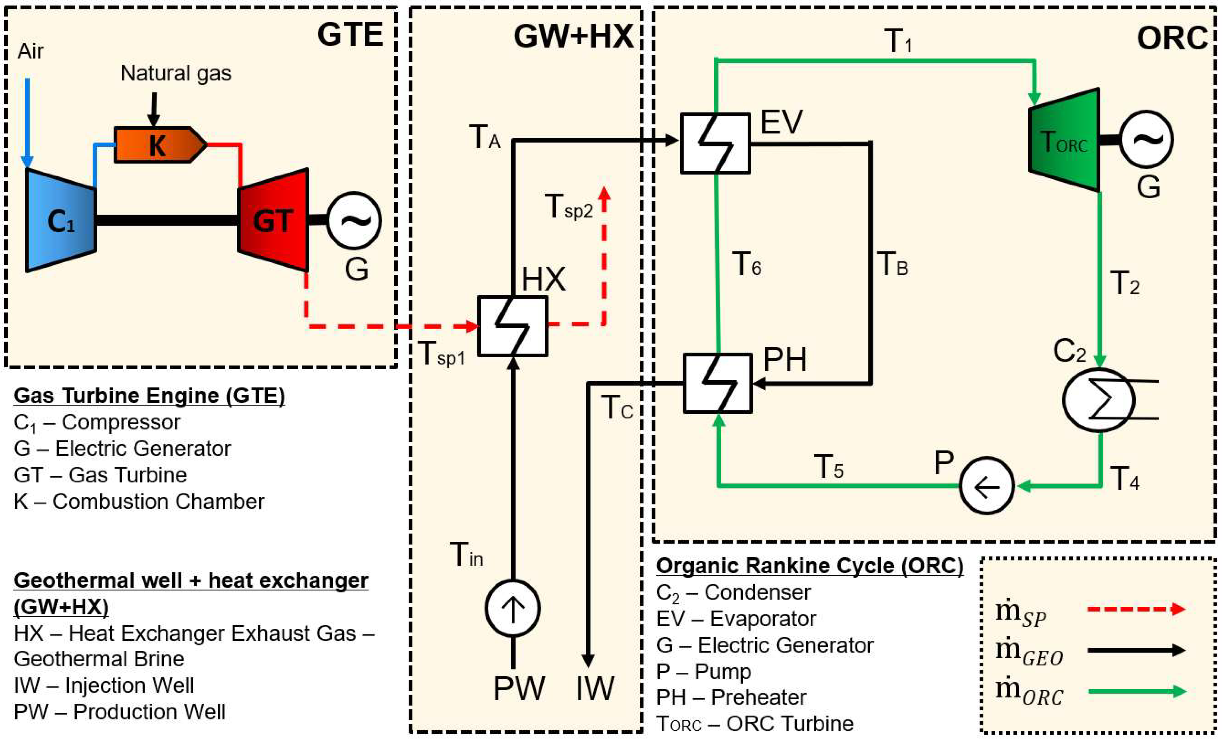
Figure 1. Schematic view of a modified ORC system supported by a gas turbine.
Sustainability 16 00075 g001
Figure 2. SPBT values as a function of electricity price and natural gas price for the lowest value SPBT of gas turbines. MD = 2000 m.
Sustainability 16 00075 g002
Figure 3. SPBT values as a function of electricity price and natural gas price for the lowest value SPBT of working fluids (titles of partly figures). MD = 2000 m.
Sustainability 16 00075 g003aSustainability 16 00075 g003b
Figure 4. SPBT values as a function of electricity price and depth of geothermal well for the lowest value SPBT of working fluids and gas turbine: R1336mzz(Z) and SGT-800. png = 0.4 USD/kg.
Sustainability 16 00075 g004
Table 1. Comparison of the basic technical parameters of the gas turbines. Source: own study based on [54].
Type of the Gas Turbine (GT)Gas Turbine SGT-50Gas Turbine SGT-100Gas Turbine SGT-300Gas Turbine SGT-400
FuelNatural gas, liquid fuel, dual fuel
Gross efficiency26%30.2%30.6%34.8%
Heat rate15,148 kJ/kWh11,914 kJ/kWh11,773 kJ/kWh10,355 kJ/kWh
Turbine speed25,500 rpm17,384 rpm14,010 rpm9500 rpm
Pressure ration7.0:114.0:113.7:116.8:1
Exhaust mass flow9.5 kg/s19.5 kg/s30.2 kg/s39.4 kg/s
Exhaust temperature600 °C545 °C542 °C555 °C
Power2 MWe5.1 MWe7.9 MWe12.9 MWe
Type of the Gas Turbine (GT)Gas Turbine SGT-800Gas Turbine SGT-A05 KB5SGas Turbine SGT-A05 KB7SGas Turbine SGT-A05 KB7HE
FuelNatural gas, liquid fuel, dual fuel
Gross efficiency41.1%29.7%32.3%33.2%
Heat rate8759 kJ/kWh12,137 kJ/kWh11,152 kJ/kWh10,848 kJ/kWh
Turbine speed6600 rpm14,200 rpm14,600 rpm14,600 rpm
Pressure ration21.1:110.3:113.9:114.1:1
Exhaust mass flow135.5 kg/s15.4 kg/s21.3 kg/s21.4 kg/s
Exhaust temperature596 °C560 °C494 °C522 °C
Power62.5 MWe4.0 MWe5.4 MWe5.8 MWe
Table 2. Properties of selected ORC working fluids. Source: own study based on [55,56,57].
Working Fluid (F)Chemical ClassTbp (K)TCR (K)PCR (MPa)ASHRAE Safety GroupASHRAE FlammabilityASHRAE ToxicityODPGWP
R600aHC272.66424.133.796A3Yes (highly flammable)No03
R134aHFC247,08374.214.0593A1Non-flammableNo01430
R152aHFC249.13386.414.5168A2Yes (medium flammable)No0124
R227eaHFC256.81374.92.925A1Non-flammableNo03230
R245faHFC288.29427.163.651A1Non-flammableNo01030
R1224yd(Z)HCFO287.77428.693.337-FlammableRelatively non-toxic00.88
R1233zd(E)HCFO291.41439.63.6237A3Yes (highly flammable)Acceptable toxicity07
R1234yfHFO243.7367.853.3822A2LYes (low flammable)No04
R1243zfHFO247.73376.933.5179-Yes (highly flammable)Toxic0149
R1336mzz(Z)HFO306.6444.52.903A3Yes (highly flammable)No09
Abbreviations are as follows: HC—hydrocarbon, HCFO—hydrochlorofluoroolefin, HFC—hydrofluorocarbon, HFO—hydrofluoroolefin.
Table 3. The heat transfer coefficient (U) values used in the study [58,63,64].
EquipmentHeating Fluid TypeHeating Fluid PhaseHeated Fluid TypeHeated Fluid PhaseU [kW/m2·K]
Heat exchangerExhaust gasGasGeothermal brineLiquid0.2
EvaporatorGeothermal brineLiquidOrganic fluidLiquid/vapor0.9
PreheaterGeothermal brineLiquidOrganic fluidLiquid0.9
CondenserOrganic fluidVapor/liquidWaterLiquid1.0
Disclaimer/Publisher’s Note: The statements, opinions and data contained in all publications are solely those of the individual author(s) and contributor(s) and not of MDPI and/or the editor(s). MDPI and/or the editor(s) disclaim responsibility for any injury to people or property resulting from any ideas, methods, instructions or products referred to in the content.