
Unveiling the Seismic Performance of Concentrically Braced Steel Frames: A Comprehensive Review


Abstract
1. Introduction
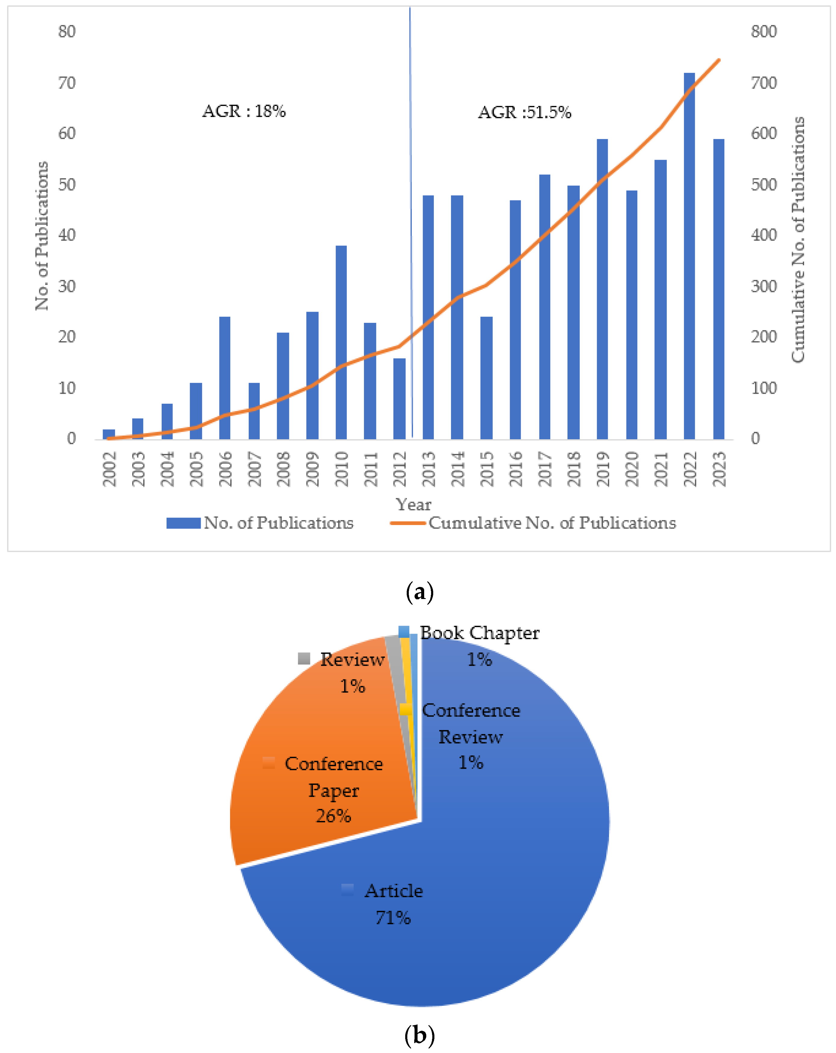
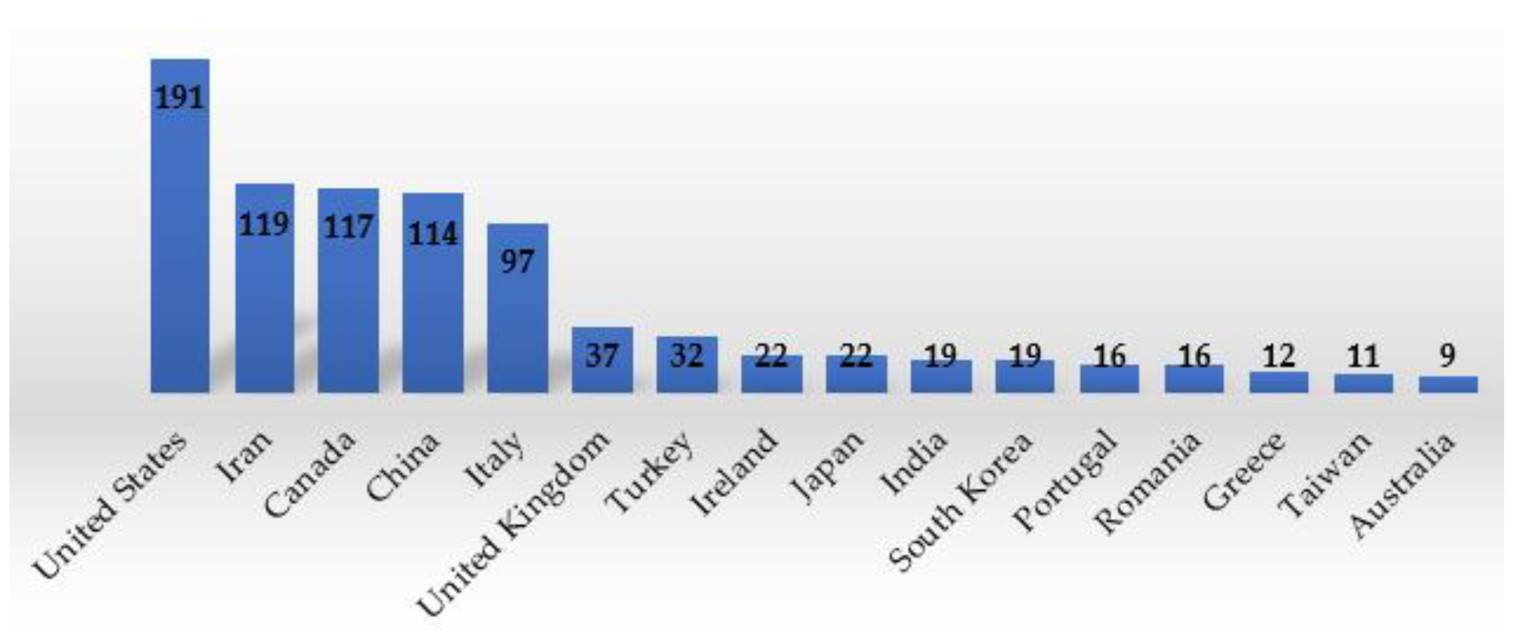
2. Literature Methodology and Statistics of Publications
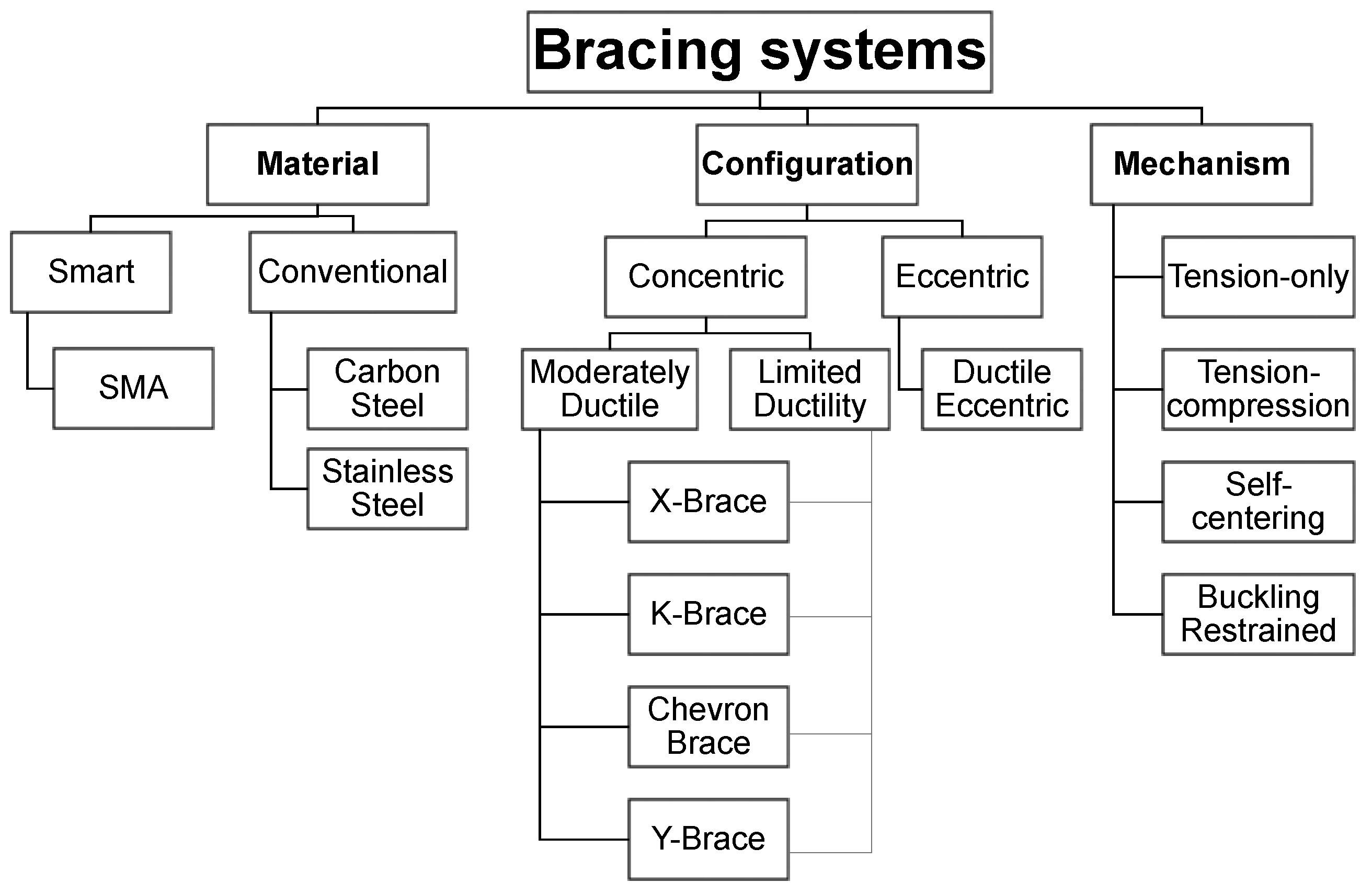
3. Classification of Braced Frames
3.1. Material-Based Classification
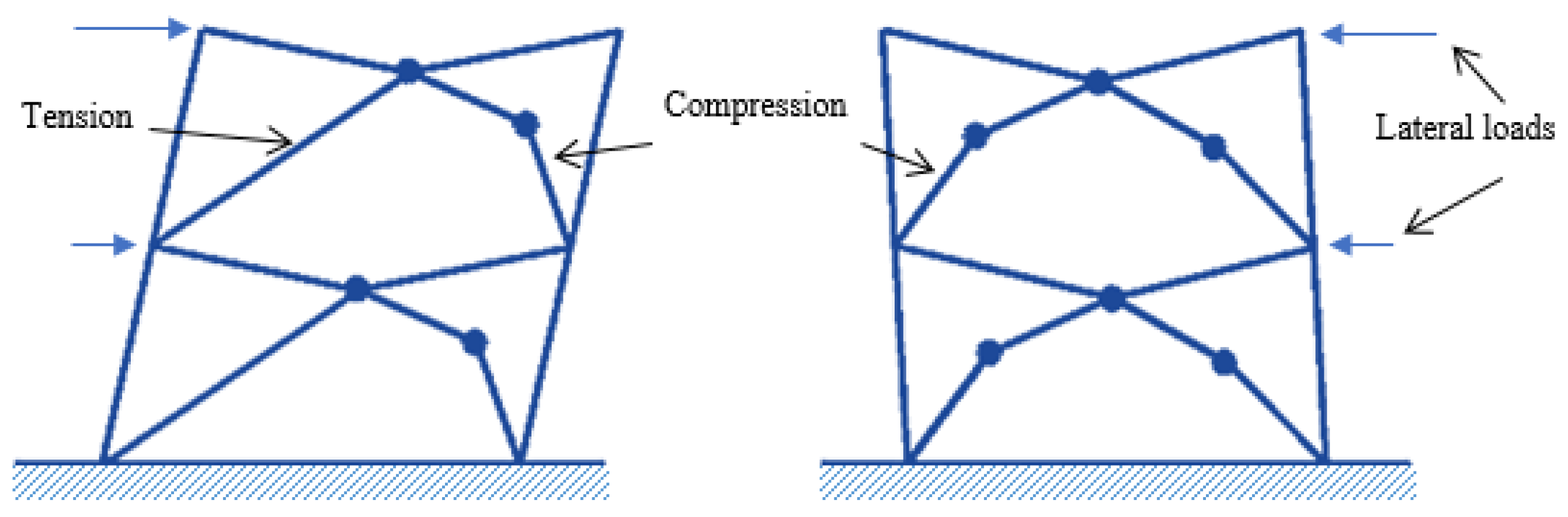
3.2. Configuration-Based Classification
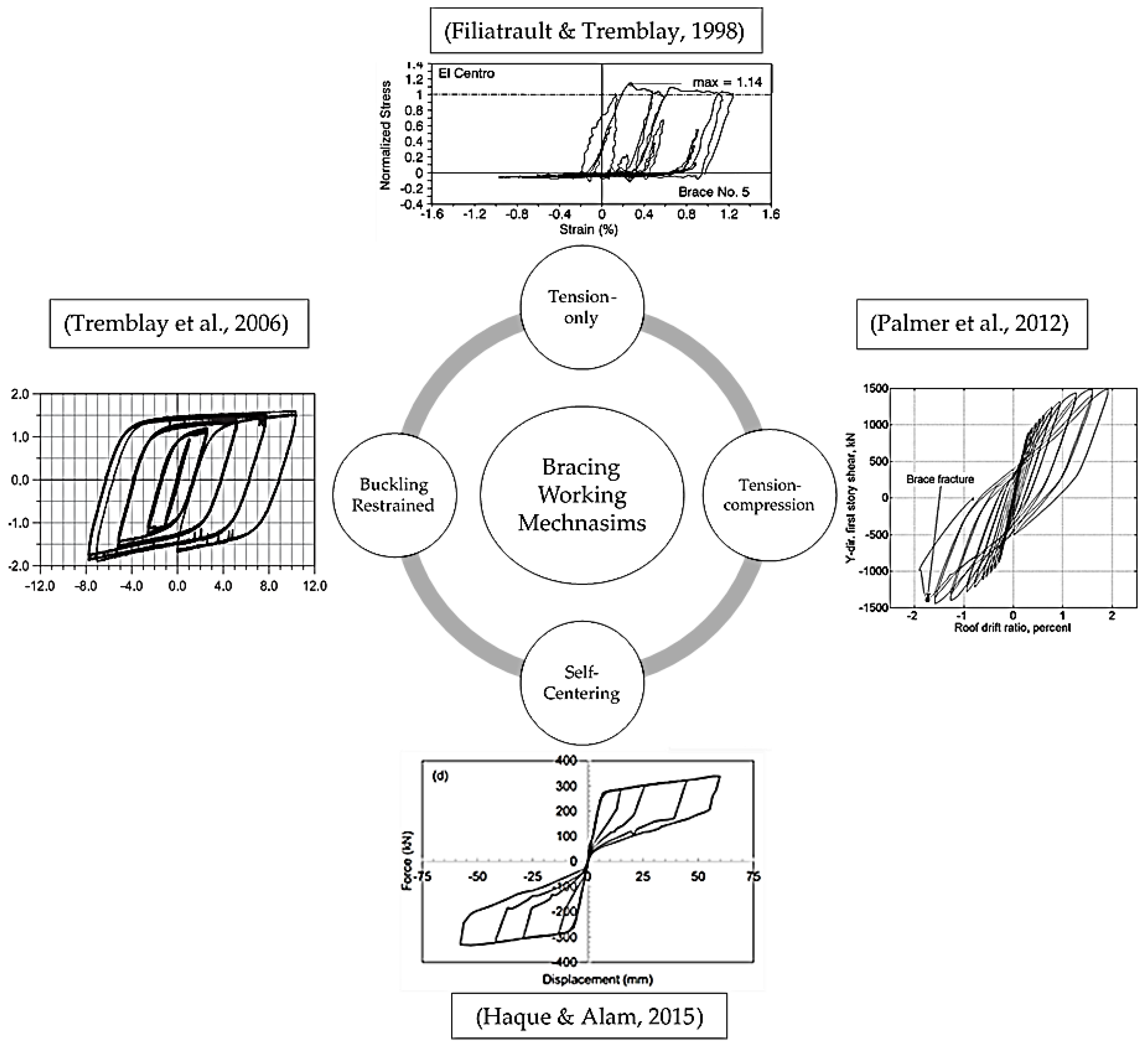
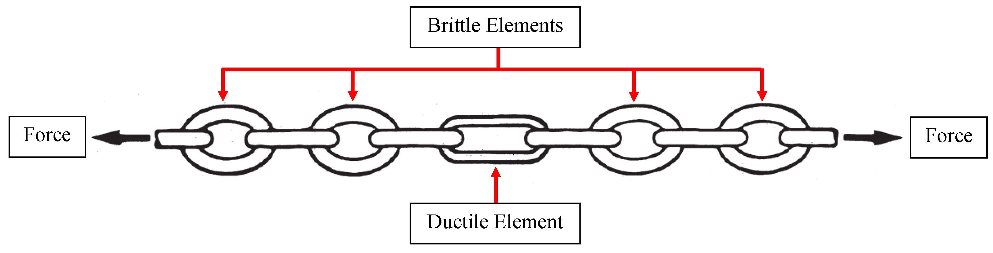
3.3. Working Mechanism-Based Classification
4. Design of Concentric Braced Frames (CBFs)
4.1. Canadian Standards
4.2. American Standards
4.3. Eurocode
4.4. Building Code of Japan
4.5. Chinese Code
5. Inelastic Seismic Response of Braced Frames
5.1. Conventional Braced Frame
5.1.1. Specimen Details
5.1.2. Loading Histories and Brace Performance
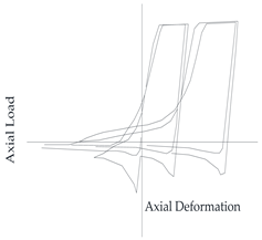
5.1.3. Sample Studies
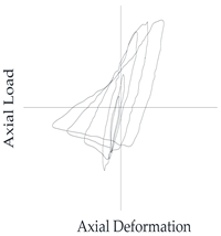
5.2. Modern Braced Frames
5.3. Self-Centering Braced Frames
6. Advancements and Challenges
7. Conclusions
- Experimental and numerical studies conducted on CBFs worldwide have increased significantly. The USA came out on top for countries across the world in this field, as per the statistics of publication. The number of publications rose with time, especially journal papers. The design philosophies adopted in most of the previous studies followed the force-based design procedures recommended by the American (ANSI/AISC 341), Canadian (CSA), European (CEN), Japanese (BCJ), and Chinese (CBI) design codes.
- A wide range of studies has been conducted on different bracing systems. Most studies focused on conventional bracing systems where various testing methods and numerical simulations were conducted and performed. While some studies included reduced-scale test specimens, others were conducted on full-scale systems. Similarly, depending on the available testing facilities, some studies used quasi-static loading with low loading rates, while others adopted real earthquake records, using shake tables. Researchers proposed new bracing ideas, generated finite-element models for the bracing systems, performed numerical simulations, and finally built prototypes and conducted experimental testing. This work has summarized and discussed the varying test programs, design approaches, and assessment methodologies.
- The newly developed systems embrace complex configurations, and use smart materials such as SMA bars and wires. The newly proposed and tested systems showed a favorable response regarding re-centering capability, energy dissipation, enhanced ductility, and minimized residual deformation. While conventional bracing systems seem to be well-developed, new and innovative systems are still emerging. The need to validate the new systems when implemented in real-life structures is a necessity. At the same time, continuous efforts will be exerted by researchers to enhance the performance of existing conventional bracing systems. This requires developing reliable rehabilitation techniques using new technologies and smart materials to upgrade their seismic performance, especially in areas of high seismicity. In addition, the need for new systems with the optimum seismic response and acceptable cost and constructability has been emphasized.
- The majority of the tests conducted in previous studies were of the quasi-cyclic nature, which suggests that potential strain-rate effects on the compressive and tensile resistance of the bracing members could not be thoroughly evaluated. To gain a more comprehensive understanding, it is advisable to conduct additional dynamic testing, using realistic time histories. This approach would allow for the assessment of the strain-rate effects and a comprehensive evaluation of the overall performance of bracing members when subjected to such loading demands.
Author Contributions
Funding
Acknowledgments
Conflicts of Interest
References
- ANSI/AISC 341–16; Seismic Provisions for Structural Steel Buildings. American Institute of Steel Construction: Chicago, IL, USA, 2016.
- Palmer, K.D.; Roeder, C.W.; Lehman, D.E.; Okazaki, T.; Shield, C.K.; Powell, J. Concentric X-braced frames with HSS bracing. Int. J. Steel Struct. 2012, 12, 443–459. [Google Scholar] [CrossRef]
- Shaback, B.; Brown, T. Behaviour of square hollow structural steel braces with end connections under reversed cyclic axial loading. Can. J. Civ. Eng. 2003, 30, 745–753. [Google Scholar] [CrossRef]
- Tremblay, R. Inelastic seismic response of steel bracing members. J. Constr. Steel Res. 2002, 58, 665–701. [Google Scholar] [CrossRef]
- Elghazouli, A.; Broderick, B.; Goggins, J.; Mouzakis, H.; Carydis, P.; Bouwkamp, J.; Plumier, A. Shake table testing of tubular steel bracing members. Proc. Inst. Civ. Eng. Struct. Build. 2005, 158, 229–241. [Google Scholar] [CrossRef]
- Gray, M.G.; Christopoulos, C.; Packer, J.A. Cast steel yielding brace system for concentrically braced frames: Concept development and experimental validations. J. Struct. Eng. 2013, 140, 04013095. [Google Scholar] [CrossRef]
- Nip, K.; Gardner, L.; Elghazouli, A. Cyclic testing and numerical modelling of carbon steel and stainless steel tubular bracing members. Eng. Struct. 2010, 32, 424–441. [Google Scholar] [CrossRef]
- Tremblay, R.; Bolduc, P.; Neville, R.; DeVall, R. Seismic testing and performance of buckling-restrained bracing systems. Can. J. Civ. Eng. 2006, 33, 183–198. [Google Scholar] [CrossRef]
- Haque, A.B.M.R.; Alam, M.S. Cyclic Performance of a Piston Based SelfCentering Bracing System. In Proceedings of the Structures Congress, Portland, OR, USA, 23–25 April 2015. [Google Scholar]
- Filiatrault, A.; Tremblay, R. Design of tension-only concentrically braced steel frames for seismic induced impact loading. Eng. Struct. 1998, 20, 1087–1096. [Google Scholar] [CrossRef]
- CSA. Design of Steel Structures; CSA-S16–14; Canadian Standards Association: Toronto, ON, Canada, 2014. [Google Scholar]
- Takeuchi, T.; Nakamura, H.; Kimura, I.; Hasegawa, H.; Saeki, E.; Watanabe, A. Buckling restrained braces and damping steel structures. U.S. Patent 7,231,743, 19 June 2007. [Google Scholar]
- CBI. National Standard of the People’s Republic of China: Code for Seismic Design of Buildings (GB50011–2010); China Building Industry Publisher: Beijing, China, 2016. [Google Scholar]
- EN 1998–1:2004; Eurocode 8: Design of Structures for Earthquake Resistance. General Rules, Seismic Actions and Rules for Buildings. European Committee for Standardization: Brussels, Belgium, 2004.
- Hasegawa, T. Introduction to the Building Standard Law: Building Regulation in Japan; The Building Standard Law of Japan; The Building Center of Japan: Tokyo, Japan, 2013. [Google Scholar]
- Paulay, T.; Priestley, M.N. Seismic Design of Reinforced Concrete and Masonry Buildings; Wiley: New York, NY, USA, 1992; Volume 768. [Google Scholar]
- Elnashai, A.S.; Di Sarno, L. Fundamentals of Earthquake Engineering: From Source to Fragility; John Wiley & Sons: Hoboken, NJ, USA, 2015. [Google Scholar]
- Plumier, A. General report on local ductility. J. Constr. Steel Res. 2000, 55, 91–107. [Google Scholar] [CrossRef]
- Brandonisio, G.; Toreno, M.; Grande, E.; Mele, E.; De Luca, A. Seismic design of concentric braced frames. J. Constr. Steel Res. 2012, 78, 22–37. [Google Scholar] [CrossRef]
- Naqash, M.T.; Mahmood, K.; Khoso, S. An overview on the seismic design of braced frames. Am. J. Civ. Eng. 2014, 2, 41–47. [Google Scholar] [CrossRef]
- Sabelli, R.; Roeder, C.W.; Hajjar, J.F. Seismic design of steel special concentrically braced frame systems. NEHRP Seism. Des. Tech. Brief 2013, 8, 1–36. [Google Scholar]
- Tremblay, R.; Bruneau, M.; Driver, R.; Metten, A.; Montgomery, C.; Rogers, C. Seismic Design of Steel Structures in Accordance with CSA-S16–09. In Proceedings of the 9th US National and 10th Canadian Conference on Earthquake Engineering, Toronto, ON, Canada, 25–29 July 2010. [Google Scholar]
- NRCC. National Building Code of Canada; National Research Council of Canada (NRCC): Ottawa, ON, Canada, 2015. [Google Scholar]
- ASCE/SEI-7; Minimum Design Loads for Buildings and Other Structures. American Society of Civil Engineers: Reston, VA, USA, 2022.
- ASCE/SEI-7; Minimum Design Loads for Buildings and Other Structures. American Society of Civil Engineers: Reston, VA, USA, 2010.
- Elghazouli, A. Seismic design procedures for concentrically braced frames. Proc. Inst. Civ. Eng. Struct. Build. 2003, 156, 381–394. [Google Scholar] [CrossRef]
- Johnson, S.M. Improved Seismic Performance of Special Concentrically Braced Frames. Ph.D. Thesis, University of Washington, Seattle, WA, USA, 2005. [Google Scholar]
- Herman, D. Further Improvements on and Understanding of SCBF Systems. Master’s Thesis, University of Washington, Seattle, WA, USA, 2006. [Google Scholar]
- Kotulka, B.A. Analysis for a Design Guide on Gusset Plates Used in Special Concentrically Braced Frames. Master’s Thesis, University of Washington, Seattle, WA, USA, 2007. [Google Scholar]
- Powell, J.A. Evaluation of Special Concentrically Braced Frames for Improved Seismic Performance and Constructability. Ph.D. Thesis, University of Washington, Seattle, WA, USA, 2010. [Google Scholar]
- Clark, K.A. Experimental Performance of Multi-Story X-Braced SCBF Systems. Ph.D. Thesis, University of Washington, Seattle, WA, USA, 2009. [Google Scholar]
- Lumpkin, E.J. Enhanced Seismic Performance of Multi-Story Special Concentrically Brace Frames Using a Balanced Design Procedure. Ph.D. Thesis, University of Washington, Seattle, WA, USA, 2009. [Google Scholar]
- Fell, B.V. Buckling and Fracture of Concentric Braces under Inelastic Cyclic Loading; University of California at Davis: Davis, CA, USA, 2006. [Google Scholar]
- Yang, F.; Mahin, S. Limiting net section failure in slotted HSS braces. Struct. Steel Educ. Counc. 2005. [Google Scholar]
- Uriz, P. Towards Earthquake Resistant Design of Concentrically Braced Steel Structures; University of California: Berkeley, CA, USA, 2005. [Google Scholar]
- Goggins, J.; Broderick, B.; Elghazouli, A.; Lucas, A. Experimental cyclic response of cold-formed hollow steel bracing members. Eng. Struct. 2005, 27, 977–989. [Google Scholar] [CrossRef]
- Han, S.-W.; Kim, W.T.; Foutch, D.A. Seismic Behavior of HSS Bracing Members according to Width–Thickness Ratio under Symmetric Cyclic Loading. J. Struct. Eng. 2007, 133, 264–273. [Google Scholar] [CrossRef]
- Tremblay, R.; Archambault, M.-H.; Filiatrault, A. Seismic response of concentrically braced steel frames made with rectangular hollow bracing members. J. Struct. Eng. 2003, 129, 1626–1636. [Google Scholar] [CrossRef]
- Lehman, D.E.; Roeder, C.W.; Herman, D.; Johnson, S.; Kotulka, B. Improved seismic performance of gusset plate connections. J. Struct. Eng. 2008, 134, 890–901. [Google Scholar] [CrossRef]
- Goggins, J.; Broderick, B.M.; Elghazouli, A.; Lucas, A. Behaviour of tubular steel members under cyclic axial loading. J. Constr. Steel Res. 2006, 62, 121–131. [Google Scholar] [CrossRef]
- Archambault, M.-H.; Tremblay, R.; Filiatrault, A. Etude du Comportement Seismique des Contreventements Ductiles en X Avec Profiles Tubulaires en Acier; Ecole Polytechnique: Palaiseau, France, 1996. [Google Scholar]
- Tremblay, R.; Filiatrault, A.; Bruneau, M.; Nakashima, M.; Prion, H.G.; DeVall, R. Seismic design of steel buildings: Lessons from the 1995 Hyogo-ken Nanbu earthquake. Can. J. Civ. Eng. 1996, 23, 727–756. [Google Scholar] [CrossRef]
- Lucas, A.S. Testing and Analysis of Steel Bracing Members for Earthquake Resistance; Trinity College Dublin: Dublin, Ireland, 2003. [Google Scholar]
- Tremblay, R.; Haddad, M.; Martinez, G.; Richard, J.; Moffatt, K. Inelastic cyclic testing of large size steel bracing members. In Proceedings of the 14th World Conference on Earthquake Engineering, Beijing, China, 12–17 October 2008. [Google Scholar]
- Veismoradi, S.; Amiri, G.G.; Darvishan, E. Probabilistic seismic assessment of Buckling Restrained Braces and Yielding Brace Systems. Int. J. Steel Struct. 2016, 16, 831–843. [Google Scholar] [CrossRef]
- Issa, A.; Mwafy, A. Fragility Assessment of Pre-Seismic Code Buildings and Emergency Facilities in the UAE. In Proceedings of the Second European Conference on Earthquake Engineering and Seismology (2ECEES), Istanbul, Turkey, 24–29 August 2014; pp. 24–29. [Google Scholar]
- Afsar Dizaj, E.; Fanaie, N.; Zarifpour, A. Probabilistic seismic demand assessment of steel frames braced with reduced yielding segment buckling restrained braces. Adv. Struct. Eng. 2018, 21, 1002–1020. [Google Scholar] [CrossRef]
- Araki, Y.; Shrestha, K.C.; Maekawa, N.; Koetaka, Y.; Omori, T.; Kainuma, R. Shaking table tests of steel frame with superelastic Cu–Al–Mn SMA tension braces. Earthq. Eng. Struct. Dyn. 2015, 45, 297–314. [Google Scholar] [CrossRef]
- Wang, W.; Fang, C.; Shen, D.; Zhang, R.; Ding, J.; Wu, H. Performance assessment of disc spring-based self-centering braces for seismic hazard mitigation. Eng. Struct. 2021, 242, 112527. [Google Scholar] [CrossRef]
- Xu, L.-H.; Fan, X.-W.; Li, Z.-X. Development and experimental verification of a pre-pressed spring self-centering energy dissipation brace. Eng. Struct. 2016, 127, 49–61. [Google Scholar] [CrossRef]
- Xu, L.H.; Fan, X.W.; Li, Z.X. Cyclic behavior and failure mechanism of self-centering energy dissipation braces with pre-pressed combination disc springs. Earthq. Eng. Struct. Dyn. 2016, 46, 1065–1080. [Google Scholar] [CrossRef]
- Chou, C.-C.; Chen, Y.-C. Development of steel dual-core self-centering braces: Quasi-static cyclic tests and finite element analyses. Earthq. Spectra 2015, 31, 247–272. [Google Scholar] [CrossRef]
- Baiguera, M.; Vasdravellis, G.; Karavasilis, T.L. Dual seismic-resistant steel frame with high post-yield stiffness energy-dissipative braces for residual drift reduction. J. Constr. Steel Res. 2016, 122, 198–212. [Google Scholar] [CrossRef]
- Zhou, Z.; Xie, Q.; Lei, X.; He, X.; Meng, S. Experimental investigation of the hysteretic performance of dual-tube self-centering buckling-restrained braces with composite tendons. J. Compos. Constr. 2015, 19, 04015011. [Google Scholar] [CrossRef]
- Xie, Q.; Zhou, Z.; Huang, J.; Zhu, D.; Meng, S. Finite-Element Analysis of Dual-Tube Self-Centering Buckling-Restrained Braces with Composite Tendons. J. Compos. Constr. 2016, 2016, 04016112. [Google Scholar] [CrossRef]
- Qiu, C.; Zhu, S. Shake table test and numerical study of self-centering steel frame with SMA braces. Earthq. Eng. Struct. Dyn. 2016, 46, 117–137. [Google Scholar] [CrossRef]
- Qiu, C.-X.; Zhu, S. Performance-based seismic design of self-centering steel frames with SMA-based braces. Eng. Struct. 2017, 130, 67–82. [Google Scholar] [CrossRef]
- Choi, E.; Youn, H.; Park, K.; Jeon, J.-S. Vibration tests of precompressed rubber springs and a flag-shaped smart damper. Eng. Struct. 2017, 132, 372–382. [Google Scholar] [CrossRef]
- Speicher, M.S.; DesRoches, R.; Leon, R.T. Investigation of an articulated quadrilateral bracing system utilizing shape memory alloys. J. Constr. Steel Res. 2017, 130, 65–78. [Google Scholar] [CrossRef]
- Wu, J.; Phillips, B.M. Passive self-centering hysteretic damping brace based on the elastic buckling mode jump mechanism of a capped column. Eng. Struct. 2017, 134, 276–288. [Google Scholar] [CrossRef]
- Issa, A.S.; Alam, M.S. Experimental and numerical study on the seismic performance of a self-centering bracing system using closed-loop dynamic (CLD) testing. Eng. Struct. 2019, 195, 144–158. [Google Scholar] [CrossRef]
- Issa, A.S.; Alam, M.S. Seismic performance of a novel single and double spring-based piston bracing. J. Struct. Eng. 2019, 145, 04018261. [Google Scholar] [CrossRef]
- Qiu, C.; Du, X. Seismic performance of multistory CBFs with novel recentering energy dissipative braces. J. Constr. Steel Res. 2020, 168, 105864. [Google Scholar] [CrossRef]
- Kari, A.; Ghassemieh, M.; Badarloo, B. Development and design of a new self-centering energy-dissipative brace for steel structures. J. Intell. Mater. Syst. Struct. 2019, 30, 924–938. [Google Scholar] [CrossRef]
- Zareie, S.; Issa, A.S.; Seethaler, R.; Zabihollah, A.; Ahmad, R. A novel SMA-magnetorheological hybrid bracing system for seismic control. Eng. Struct. 2021, 244, 112709. [Google Scholar] [CrossRef]
- Atasever, K.; Inanaga, S.; Takeuchi, T.; Terazawa, Y.; Celik, O.C. Experimental and numerical studies on buckling restrained braces with posttensioned carbon fiber composite cables. Earthq. Eng. Struct. Dyn. 2020, 49, 1640–1661. [Google Scholar] [CrossRef]
- Yousef-beik, S.M.M.; Veismoradi, S.; Zarnani, P.; Quenneville, P. A new self-centering brace with zero secondary stiffness using elastic buckling. J. Constr. Steel Res. 2020, 169, 106035. [Google Scholar] [CrossRef]
- Zhang, H.; Quan, L.; Lu, X. Experimental hysteretic behavior and application of an assembled self-centering buckling-restrained brace. J. Struct. Eng. 2022, 148, 04021302. [Google Scholar] [CrossRef]
- Issa, A.; Rahgozar, N.; Alam, M.S. Seismic response evaluation of spring-based piston braced frames by employing closed-loop dynamic (CLD) testing. Eng. Struct. 2023, 284, 115983. [Google Scholar] [CrossRef]
- Issa, A.; Rahgozar, N.; Alam, M.S. Experimental investigation and seismic analysis of a novel self-centering piston-based bracing archetype with polyurethane cores. Eng. Struct. 2023, 283, 115735. [Google Scholar] [CrossRef]
- Joseph, R.; Mwafy, A.; Alam, M.S. Seismic performance upgrade of substandard RC buildings with different structural systems using advanced retrofit techniques. J. Build. Eng. 2022, 59, 105155. [Google Scholar] [CrossRef]
- Issa, A.S.; Mwafy, A.; Alam, M.S. Seismic vulnerability assessment of pre-code frame building retrofitted using buckling restrained braces. In Proceedings of the 6th International Conference on Engineering Mechanics and Materials, San Diego, CA, USA, 4–7 June 2017. [Google Scholar]


| CBFs | |||
|---|---|---|---|
| Component | MD | LD | |
| Bracing System | Tension–compression | Max 8 stories | Max 12 stories |
| Chevron | Max 8 stories | Max 12 stories | |
| Tension only | Max 4 stories | Max 2 stories | |
| Diagonal Bracing Members | KL/r * < 200 | KL/r < 300 | |
| Bracing Connections | Min eccentricity | Waived | |
| Structural Type | Ductility Class | |
|---|---|---|
| Medium | High | |
| Moment-resisting frames (MRFs) | q = 4.0 | q = 5 * |
| Diagonal-braced frames (X-CBFs) | q = 4.0 | q = 4.0 |
| Chevron-braced frames (V-CBFs) | q = 2.0 | q = 2.5 |
| Moment-resisting frames with concentric braces | q = 4.0 | q = 4 * |
| Type of MRF | Brace Type | ||||||
|---|---|---|---|---|---|---|---|
| BA or | BB | BC | |||||
| β = 0 | β ≤ 0.3 | 0.3 < β ≤ 0.7 | β > 0.7 | β ≤ 0.3 | 0.3 < β ≤ 0.5 | β > 0.5 | |
| FA | 0.25 | 0.25 | 0.30 | 0.35 | 0.30 | 0.35 | 0.40 |
| FB | 0.30 | 0.30 | 0.30 | 0.35 | 0.30 | 0.35 | 0.40 |
| FC | 0.35 | 0.35 | 0.35 | 0.40 | 0.35 | 0.40 | 0.45 |
| FD | 0.40 | 0.40 | 0.45 | 0.50 | 0.40 | 0.45 | 0.50 |
| Type of SFRS in the Canadian Code | IEFaSa (0.2) | IEFaSa (1.0) | ||||
|---|---|---|---|---|---|---|
| <0.2 | ≥0.2 to <0.35 | ≥0.35 to ≤0.75 | >0.75 | >0.3 | ||
| Moderately ductile CBFs | Non-chevron braces Chevron braces Tension only braces | NL | NL | 40 m | 40 m | 40 m |
| NL | NL | 40 m | 40 m | 40 m | ||
| NL | NL | 20 m | 20 m | 20 m | ||
| Limited ductility CBFs | Non-chevron braces Chevron braces Tension only braces | NL | NL | 60 m | 60 m | 60 m |
| NL | NL | 60 m | 60 m | 60 m | ||
| NL | NL | 40 m | 40 m | 40 m | ||
| Type of LFRS (dual systems) in Chinese Code | Seismic fortification intensity * | |||||
| 6.7 | 7.5 | 8 | 8.5 | 9 | ||
| Moderately ductile CBFs | 220 m | 200 m | 180 m | 150 m | 120 m | |
| Study | Test No. | Shape | Type | Axis | Buckling | Steel | Ag | Fy | LB | LH | λ | dy | Displacement History | |
|---|---|---|---|---|---|---|---|---|---|---|---|---|---|---|
| (mm2) | (MPa) | (mm) | (mm) | (mm) | (mm) | |||||||||
| Tremblay [4] * | S1A | RHS 127 × 76 × 4.8 | 1 | X | Out | G40.21-350W | 1790 | 353 | 0.67 | 4007 | 4610 | 1.312 | 7.922 | 1-T # |
| S1B | RHS 127 × 76 × 4.8 | 1 | X | Out | G40.21-350W | 1790 | 353 | 0.67 | 4007 | 4610 | 1.312 | 7.922 | 1-C # | |
| S2A | RHS 102 × 76 × 4.8 | 1 | X | Out | G40.21-350W | 1550 | 346 | 0.67 | 4089 | 4611 | 1.502 | 7.798 | 1-T | |
| S2B | RHS 102 × 76 × 4.8 | 1 | X | Out | G40.21-350W | 1550 | 346 | 0.67 | 4089 | 4611 | 1.506 | 7.798 | 1-C | |
| S3A | RHS 76 × 76 × 4.8 | 1 | – | Out | G40.21-350W | 1310 | 332 | 0.67 | 4179 | 4619 | 2.014 | 8.126 | 1-T | |
| S3B | RHS 76 × 76 × 4.8 | 1 | – | Out | G40.21-350W | 1310 | 332 | 0.67 | 4179 | 4619 | 1.99 | 8.126 | 1-C | |
| S4A | RHS 127 × 64 × 4.8 | 1 | X | Out | G40.21-350W | 1670 | 346 | 0.53 | 4049 | 4611 | 1.366 | 7.802 | 1-T | |
| S4B | RHS 127 × 64 × 4.8 | 1 | X | Out | G40.21-350W | 1670 | 346 | 0.53 | 4049 | 4611 | 1.365 | 7.802 | 1-C | |
| S5A | RHS 102 × 76 × 6.4 | 1 | X | Out | G40.21-350W | 1990 | 388 | 0.67 | 4089 | 4614 | 1.644 | 8.622 | 1-T | |
| S5B | RHS 102 × 76 × 6.4 | 1 | X | Out | G40.21-350W | 1990 | 388 | 0.67 | 4089 | 4614 | 1.658 | 8.622 | 1-C | |
| S1QA | RHS 127 × 76 × 4.8 | 1 | X | Out | G40.21-350W | 1790 | 353 | 0.67 | 4009 | 4610 | 1.314 | 7.926 | 2-T | |
| S1QB | RHS 127 × 76 × 4.8 | 1 | X | Out | G40.21-350W | 1790 | 353 | 0.67 | 4009 | 4610 | 1.319 | 7.926 | 2-C | |
| S4QA | RHS 127 × 64 × 4.8 | 1 | X | Out | G40.21-350W | 1670 | 346 | 0.53 | 4049 | 4611 | 1.36 | 7.521 | 2-T | |
| S4QB | RHS 127 × 64 × 4.8 | 1 | X | Out | G40.21-350W | 1670 | 346 | 0.53 | 4049 | 4611 | 1.338 | 7.521 | 2-C | |
| Tremblay [4] * | 1 | W8 × 21 | 4 | X | In | A36 | 3974 | 288.4 | 0.71 | 3340 | 3810 | 1.439 | 4.816 | 3-C |
| 2 | W6 × 25 | 4 | X | In | A36 | 4735 | 277.9 | 0.73 | 1085 | 1555 | 0.478 | 1.508 | 4-C | |
| 3 | W6 × 20 | 4 | X | In | A36 | 3787 | 276.2 | 0.9 | 2599 | 3069 | 0.953 | 3.589 | 4-C | |
| 4 | W6 × 20 | 4 | X | In | A36 | 3787 | 276.2 | 0.9 | 2599 | 3069 | 0.953 | 3.589 | 4-C | |
| 5 | W6 × 20 | 4 | X | In | A36 | 3787 | 276.2 | 0.9 | 2599 | 3069 | 0.953 | 3.589 | 3-T | |
| 6 | W6 × 16 | 4 | X | In | A36 | 3058 | 305.8 | 0.54 | 2477 | 2947 | 1.497 | 3.788 | 3-C | |
| 7 | W6 × 15.5 | 4 | X | In | A36 | 2858 | 348.6 | 1.25 | 1014 | 1484 | 0.532 | 1.767 | 3-T | |
| 8 | 2-L6 × 3.5 × 0.375 | 4 | X | In | A36 | 4413 | 281.1 | 1.01 | 2356 | 2825 | 1.13 | 3.311 | 3-C | |
| 9 | 2-L5 × 3.5 × 0.375 | 4 | X | In | A36 | 3929 | 300.4 | 1.01 | 1014 | 1484 | 0.803 | 1.523 | 3-C | |
| 10 | 2-L4 × 3.5 × 0.375 | 4 | Y | In | A36 | 3445 | 305.9 | 1.16 | 3340 | 3810 | 1.482 | 5.109 | 3-C | |
| 11 | 2-C8 × 11.5 | 4 | X | In | A36 | 4361 | 268.5 | 0.63 | 2526 | 2996 | 1.398 | 3.391 | 3-C | |
| 12 | WT5 × 22.5 | 4 | Y | In | A36 | 4290 | 261.1 | 1.57 | 2069 | 2538 | 0.927 | 2.701 | 3-C | |
| 13 | WT8 × 22.5 | 4 | X | In | A36 | 4290 | 284.7 | 0.68 | 2721 | 3191 | 1.03 | 3.873 | 3-T | |
| 14 | Pipe 4.5 × 0.237 | 4 | – | In | A53, gr. B | 2045 | 354.8 | 0.51 | 2599 | 3069 | 1.073 | 4.611 | 4-C | |
| 15 | Pipe 4.5 × 0.237 | 4 | – | In | A53, gr. B | 2045 | 354.8 | 0.51 | 2599 | 3069 | 1.073 | 4.611 | 3-C | |
| 16 | Pipe 4.5 × 0.337 | 4 | – | In | A53, gr. B | 2845 | 192.9 | 0.36 | 2538 | 3008 | 0.791 | 2.448 | 3-C | |
| 17 | RHS 4 × 4 × 0.250 | 4 | – | In | A501 | 2316 | 393.4 | 0.57 | 2578 | 3048 | 1.122 | 5.071 | 5-C | |
| 18 | RHS 4 × 4 × 0.500 | 4 | – | In | A501 | 4103 | 565 | 0.19 | 2295 | 2765 | 1.322 | 6.483 | 6-C | |
| 19 | W6 × 20 | 5 | X | In | A36 | 3787 | 276.2 | 0.9 | 1957 | 1804 | 0.476 | 2.702 | 4-C | |
| 20 | 2-L6 × 3.5 × 0.375 | 5 | X | In | A36 | 4413 | 281.1 | 1.01 | 3801 | 3614 | 1.13 | 5.343 | 4-C | |
| 21 | Pipe 4.5 × 0.375 | 5 | – | In | A53, gr. B | 2845 | 192.6 | 0.36 | 1957 | 1843 | 0.43 | 1.888 | 4-C | |
| 22 | RHS 4 × 4 × 0.500 | 5 | – | In | A501 | 4103 | 565 | 0.19 | 3712 | 3610 | 1.321 | 10.49 | 6-C | |
| 23 | W5 × 16 | 5 | X | In | A36 | 3019 | 291 | 0.75 | 3423 | 3296 | 0.963 | 4.98 | 4-C | |
| 24 | Pipe 4.0 × 0.226 | 5 | – | In | A53, gr. B | 1729 | 338.3 | 0.48 | 3654 | 3552 | 1.047 | 6.181 | 4-C | |
| Tremblay [4] * | WW1 | W10 × 15 | 3 | X | In | A36 | 2845 | 310 | 0.8 | 3600 | 3397 | 1.097 | 5.58 | 7-T |
| WW3 | W5 × 15.5 | 3 | X | In | A36 | 2941 | 289 | 0.75 | 3600 | 3346 | 0.631 | 5.202 | 7-T | |
| WW4 | W8 × 15 | 3 | X | In | A36 | 2865 | 289 | 0.69 | 3600 | 3396 | 0.979 | 5.202 | 7-T | |
| WW5 | W6 × 9 | 3 | X | In | A36 | 1729 | 330.7 | 1.01 | 3600 | 3397 | 1.013 | 5.953 | 7-T | |
| WW6 | W6 × 20 | 3 | X | In | A36 | 3787 | 310.1 | 0.9 | 3600 | 3294 | 0.592 | 5.582 | 7-T | |
| TW2 | RHS 5 × 3 × 0.250 | 3 | X | In | A500, gr. B | 2316 | 379 | 0.86 | 3600 | 3448 | 0.825 | 6.822 | 7-T | |
| TW3 | RHS 4 × 2 × 0.250 | 3 | X | In | A500, gr. B | 1671 | 413.4 | 0.65 | 3600 | 3498 | 1.332 | 7.441 | 7-T | |
| TW4 | RHS 7 × 5 × 0.250 | 3 | X | In | A500, gr. B | 3606 | 441 | 1.29 | 3600 | 3346 | 0.527 | 7.938 | 7-T | |
| TW6 | RHS 6 × 3 × 0.188 | 3 | X | In | A500, gr. B | 2026 | 427.2 | 1.51 | 3600 | 3448 | 0.841 | 7.69 | 7-T | |
| Tremblay [4] * | 1 | RHS 5 × 5 × 0.188 | 2 | – | Out | A500, gr. B | 2271 | 425.8 | 1.22 | 2946 | 3429 | 0.864 | 6.272 | 7-C |
| 2 | RHS 5 × 5 × 0.188 | 2 | – | Out | A500, gr. B | 2271 | 429.9 | 1.22 | 3200 | 3429 | 0.511 | 6.878 | 7-C | |
| 4 | RHS 4 × 4 × 0.125 | 2 | – | Out | A500, gr. B | 1226 | 399.6 | 1.51 | 3200 | 3429 | 0.612 | 6.394 | 7-C | |
| 5 | RHS 4 × 4 × 0.250 | 2 | – | Out | A500, gr. B | 2316 | 509.9 | 0.65 | 3099 | 3454 | 1.23 | 7.901 | 8-C | |
| 6 | RHS 4 × 4 × 0.250 | 2 | – | Out | A500, gr. B | 2316 | 509.9 | 0.65 | 3299 | 3480 | 0.729 | 8.411 | 8-C | |
| 7 | RHS 4 × 4 × 0.250 | 2 | – | Out | A500, gr. B | 2316 | 509.9 | 0.65 | 3299 | 3480 | 0.729 | 8.411 | 8-C | |
| Tremblay [4] * | 1 | 150 UC 30.0 | 4 | X | In | AS3679.1-300 | 3945 | 311.2 | 0.98 | 2416 | 2056 | 1.005 | 3.76 | 9-T |
| 2 | 150 UC 30.0 | 4 | X | In | AS3679.1-300 | 3945 | 311.2 | 0.98 | 1652 | 2292 | 0.753 | 2.571 | 9-C | |
| 3 | 150 UC 30.0 | 6 | X | In | AS3679.1-300 | 3945 | 311.2 | 0.98 | 3056 | 2756 | 0.453 | 4.756 | 9-T | |
| Tremblay [4] * | T633H | RHS 6 × 3 × 0.188 | 2 | X | In | A500, gr. B | 2026 | 372.1 | 1.51 | 3023 | 2871 | 0.663 | 5.624 | 7-T |
| T424H | RHS 4 × 2 × 0.250 | 2 | X | In | A500, gr. B | 1671 | 372.1 | 0.65 | 3150 | 3048 | 1.102 | 5.861 | 7-T | |
| T422H | RHS 4 × 2 × 0.125 | 2 | X | In | A500, gr. B | 903 | 372.1 | 1.51 | 3150 | 3048 | 1.057 | 5.861 | 7-T | |
| Tremblay [4] * | 1B | RHS 127 × 127 × 8.0 | 7 | – | Out | G40.21-350W | 3620 | 421 | 0.68 | 3350 | 3401 | 0.788 | 7.052 | 10-C |
| 2A | RHS 152 × 152 × 8.0 | 7 | – | Out | G40.21-350W | 4430 | 442 | 0.86 | 3950 | 3995 | 0.797 | 8.73 | 10-C | |
| 2B | RHS 152 × 152 × 9.5 | 7 | – | Out | G40.21-350W | 5210 | 442 | 0.68 | 3950 | 3989 | 0.785 | 8.73 | 10-C | |
| 3A | RHS 127 × 127 × 6.4 | 7 | – | Out | G40.21-350W | 2960 | 461 | 0.91 | 4350 | 4403 | 0.991 | 10.03 | 10-C | |
| 3B | RHS 127 × 127 × 8.0 | 7 | – | Out | G40.21-350W | 3620 | 421 | 0.68 | 4350 | 4398 | 0.96 | 9.157 | 10-C | |
| 3C | RHS 27 × 127 × 9.5 | 7 | – | Out | G40.21-350W | 4240 | 461 | 0.53 | 4350 | 4382 | 0.941 | 10.03 | 10-C | |
| 4A | RHS 152 × 152 × 8.0 | 7 | – | Out | G40.21-350W | 4430 | 442 | 0.86 | 4850 | 4897 | 0.95 | 10.72 | 10-C | |
| 4B | RHS 152 × 152 × 9.5 | 7 | – | Out | G40.21-350W | 5210 | 442 | 0.68 | 4850 | 4882 | 0.894 | 10.72 | 10-C | |
| Tremblay [4] * | SIC1 | H-50 × 50 × 6 × 6 | 3 | X | In | SS-41 | 851 | 289 | 0.44 | 984.7 | 885 | 0.479 | 1.423 | 11-C |
| SIC2 | H-50 × 50 × 6 × 6 | 3 | X | In | SS-41 | 837 | 289 | 0.45 | 1970 | 1870 | 0.957 | 2.847 | 11-C | |
| SIC3 | H-50 × 50 × 6 × 6 | 3 | X | In | SS-41 | 819 | 257 | 0.45 | 2972 | 2872 | 1.38 | 3.819 | 11-C | |
| SOC1 | H-50 × 50 × 6 × 6 | 3 | Y | In | SS-41 | 839 | 289 | 0.44 | 989.3 | 889 | 0.31 | 1.43 | 11-C | |
| SOC1 | H-50 × 50 × 6 × 6 | 3 | Y | Out | SS-41 | 839 | 289 | 0.44 | 989.3 | 889 | 0.486 | 1.43 | 11-C | |
| SOC2 | H-50 × 50 × 6 × 6 | 3 | Y | Out | SS-41 | 843 | 289 | 0.44 | 1970 | 1870 | 0.953 | 2.847 | 11-C | |
| SOC3 | H-50 × 50 × 6 × 6 | 3 | Y | Out | SS-41 | 824 | 257 | 0.44 | 2968 | 2868 | 1.375 | 3.814 | 11-C | |
| Tremblay [4] * | RHS1 | RHS 150 × 100 × 6 | 4 | X | In | AS1163-C350 | 2730 | 449 | 1.35 | 2064 | 2704 | 1.207 | 4.634 | 12-T |
| RHS2 | RHS 150 × 100 × 6 | 4 | X | In | AS1163-C350 | 2730 | 449 | 1.35 | 1388 | 2028 | 0.905 | 3.116 | 12-T | |
| RHS3 | RHS 150 × 100 × 6 | 6 | X | In | AS1163-C350 | 2730 | 449 | 1.35 | 2704 | 2504 | 0.603 | 6.07 | 12-T | |
| Johnson [27] | HSS2 | HSS5 × 5 × 3/8 | Out | A500, Gr. B | 3987 | 482 | 0.75 | 1.213 | ||||||
| HSS3 | HSS5 × 5 × 3/8 | Out | A500, Gr. B | 3987 | 482 | 0.75 | 1.206 | |||||||
| HSS4 | HSS5 × 5 × 3/8 | Out | A500, Gr. B | 3987 | 504 | 0.77 | 1.242 | |||||||
| HSS5 | HSS5 × 5 × 3/8 | Out | A500, Gr. B | 3987 | 504 | 0.77 | 1.294 | |||||||
| Herman [28] | HSS6 | HSS5 × 5 × 3/8 | Out | A500, Gr. B | 3987 | 446 | 0.72 | 1.221 | ||||||
| HSS7 | HSS5 × 5 × 3/8 | Out | A500, Gr. B | 3987 | 446 | 0.72 | 0.994 | |||||||
| HSS8 | HSS5 × 5 × 3/8 | Out | A500, Gr. B | 3987 | 446 | 0.72 | 1.139 | |||||||
| HSS9 | HSS5 × 5 × 3/8 | Out | A500, Gr. B | 3987 | 446 | 0.72 | 1.159 | |||||||
| HSS10 | HSS5 × 5 × 3/8 | Out | A500, Gr. B | 3987 | 454 | 0.73 | 1.180 | |||||||
| Kotulka [29] | HSS11 | HSS5 × 5 × 3/8 | Out | A500, Gr. B | 3987 | 454 | 0.73 | 0.983 | ||||||
| HSS12 | HSS5 × 5 × 3/8 | Out | A500, Gr. B | 3987 | 454 | 0.73 | 1.063 | |||||||
| HSS13 | HSS5 × 5 × 3/8 | Out | A500, Gr. B | 3987 | 454 | 0.73 | 1.241 | |||||||
| HSS14 | HSS5 × 5 × 3/8 | Out | A500, Gr. B | 3987 | 454 | 0.73 | 1.228 | |||||||
| HSS15 | HSS5 × 5 × 3/8 | Out | A500, Gr. B | 3987 | 454 | 0.73 | 1.254 | |||||||
| Powell [30] | HSS17 | HSS5 × 5 × 3/8 | Out | A500, Gr. B | 3987 | 454 | 0.73 | 1.239 | ||||||
| HSS24 | HSS5 × 5 × 3/8 | Out | A500, Gr. B | 3987 | 446 | 0.72 | 1.218 | |||||||
| HSS25 | HSS5 × 5 × 3/8 | Out | A500, Gr. B | 3987 | 446 | 0.72 | 0.994 | |||||||
| Clark [31] | TCBF1-1 | HSS125 × 125 × 9 | Out | A500, Gr. B | 3987 | 444 | 0.72 | 0.846 | ||||||
| TCBF1-3 | HSS125 × 125 × 9 | Out | A500, Gr. B | 3987 | 445 | 0.72 | 1.045 | |||||||
| Lumpkin [32] | TCBF2-1 | HSS5 × 5 × 3/8 | Out | A500, Gr. B | 3987 | 463 | 0.74 | 0.991 | ||||||
| Fell [33] | Kavinde-1 | HSS4 × 4 × 1/4 | Out | A500, Gr. B | 2174 | 317 | 0.77 | 0.763 | ||||||
| Kavinde-12 | HSS4 × 4 × 1/4 | Out | A500, Gr. B | 2174 | 317 | 0.77 | 0.763 | |||||||
| Kavinde-14 | HSS4 × 4 × 3/8 | Out | A500, Gr. B | 3084 | 317 | 0.46 | 0.854 | |||||||
| Yang and Mahin [34] | Yang-4 | HSS6 × 6 × 3/8 | Out | A500, Gr. B | 5213 | 414 | 0.88 | 0.569 | ||||||
| Yang-5 | HSS6 × 6 × 3/8 | Out | A500, Gr. B | 5213 | 414 | 0.88 | 0.569 | |||||||
| Uriz [35] | Patxi-SCBF-1 | HSS6 × 6 × 3/8 | Out | A500, Gr. B | 5213 | 418 | 0.88 | 0.666 | ||||||
| Goggins et al. [36] | Broderick-S1-40H | SHS 40 × 40 × 2.5 | Out | S235JRH | 375 | 270 | 0.65 | 0.419 | ||||||
| Broderick-S1-20H | SHS 20 × 20 × 2.5 | Out | S235JEH | 144 | 322 | 0.36 | 0.950 | |||||||
| Han et al. [37] | Han-S77-28 | HSS100 × 100 × 3.2 | Out | SPRS400 | 1239 | 402 | 1.72 | 1.097 | ||||||
| Tremblay et al. [38] | S1A-S1B | RHS 127 × 76 × 4.8 | 1 | X | Out | CSA-G40.21M-350W | 1790 | 395 | 0.72 | 4007 | 4615 | 1.31 | 7.92 | 1 |
| S2A-S2B | RHS 102 × 76 × 4.8 | 1 | X | Out | CSA-G40.21M-350W | 1550 | 381 | 0.71 | 4089 | 4615 | 1.5 | 7.8 | 1 | |
| S3A-S3B | RHS 76 × 76 × 4.8 | 1 | X | Out | CSA-G40.21M-350W | 1310 | 389 | 0.72 | 4179 | 4615 | 2.01 | 8.13 | 1 | |
| S4A-S4B | RHS 127 × 64 × 4.8 | 1 | X | Out | CSA-G40.21M-350W | 1670 | 385 | 0.55 | 4049 | 4615 | 1.37 | 7.8 | 1 | |
| S5A-S5B | RHS 102 × 76 × 6.4 | 1 | X | Out | CSA-G40.21M-350W | 1990 | 422 | 0.50 | 4089 | 4615 | 1.64 | 8.62 | 1 | |
| S1QA-S1QB | RHS 127 × 76 × 4.8 | 1 | X | Out | CSA-G40.21M-350W | 1790 | 395 | 0.72 | 4009 | 4615 | 1.31 | 7.93 | 2 | |
| S4QA-S4QB | RHS 127 × 64 × 4.8 | 1 | X | Out | CSA-G40.21M-350W | 1670 | 372 | 0.54 | 4049 | 4615 | 1.36 | 7.52 | 2 | |
| X1B | RHS 102 × 76 × 4.8 | 1 | X | Out | CSA-G40.21M-350W | 1550 | 386 | 0.71 | 4089 | 4615 | 0.84 | 7.9 | 1 | |
| X2A | RHS 76 × 76 × 4.8 | 1 | X | Out | CSA-G40.21M-350W | 1550 | 389 | 0.72 | 4179 | 4615 | 1.07 | 8.13 | 1 | |
| X2B | RHS 76 × 76 × 4.8 | 1 | X | Out | CSA-G40.21M-350W | 1550 | 389 | 0.72 | 4179 | 4615 | 1.07 | 8.3 | 1 | |
| X3B | RHS 76 × 51 × 4.8 | 1 | X | Out | CSA-G40.21M-350W | 1310 | 414 | 0.74 | 4249 | 4615 | 1.52 | 8.79 | 1 | |
| X4B | RHS 64 × 64 × 3.8 | 1 | X | Out | CSA-G40.21M-350W | 872 | 394 | 0.76 | 4249 | 4615 | 1.27 | 8.37 | 1 | |
| X6B | RHS 64 × 64 × 4.8 | 1 | X | Out | CSA-G40.21M-350W | 1060 | 426 | 0.58 | 4249 | 4615 | 1.27 | 9.06 | 1 | |
| X6C | RHS 64 × 64 × 4.8 | 1 | X | Out | CSA-G40.21M-350W | 1060 | 397 | 0.56 | 4249 | 4615 | 1.27 | 8.43 | 1 | |
| X1QB | RHS 102 × 76 × 4.8 | 1 | X | Out | CSA-G40.21M-350W | 1550 | 381 | 0.71 | 4089 | 4615 | 0.83 | 7.79 | 2 | |
| X2QB | RHS 76 × 76 × 4.8 | 1 | X | Out | CSA-G40.21M-350W | 1310 | 389 | 0.72 | 4179 | 4615 | 1.08 | 8.3 | 2 | |
| X4QB | RHS 64 × 64 × 3.8 | 1 | X | Out | CSA-G40.21M-350W | 872 | 387 | 0.76 | 4249 | 4615 | 1.26 | 8.23 | 2 | |
| Lehman et al. [39] | HSS-1 | HSS5 × 5 × 3/8 | 2 | X | Out | A500 | 3987 | 483 | 3420 | 11-T | ||||
| HSS-2 | HSS5 × 5 × 3/8 | 2 | X | Out | A500 | 3987 | 483 | 4010 | 11-T | |||||
| HSS-3 | HSS5 × 5 × 3/8 | 2 | X | Out | A500 | 3987 | 483 | 4010 | 11-T | |||||
| HSS-4 | HSS5 × 5 × 3/8 | 2 | X | Out | A500 | 3987 | 505 | 3900 | 11-T | |||||
| HSS-5 | HSS5 × 5 × 3/8 | 2 | X | Out | A500 | 3987 | 505 | 4010 | 11-T | |||||
| HSS-6 | HSS5 × 5 × 3/8 | 2 | X | Out | A500 | 3987 | 446 | 4010 | 11-T | |||||
| HSS-7 | HSS5 × 5 × 3/8 | 2 | X | Out | A500 | 3987 | 446 | 3790 | 11-T | |||||
| HSS-8 | HSS5 × 5 × 3/8 | 2 | X | Out | A500 | 3987 | 446 | 4120 | 11-T | |||||
| HSS-9 | HSS5 × 5 × 3/8 | 2 | X | Out | A500 | 3987 | 446 | 4010 | 11-T | |||||
| HSS-10 | HSS5 × 5 × 3/8 | 2 | X | Out | A500 | 3987 | 454 | 3990 | 11-T | |||||
| HSS-11 | HSS5 × 5 × 3/8 | 2 | X | Out | A500 | 3987 | 454 | 3790 | 11-T | |||||
| HSS-12 | HSS5 × 5 × 3/8 | 2 | X | Out | A500 | 3987 | 454 | 3420 | 11-T | |||||
| HSS-13 | HSS5 × 5 × 3/8 | 2 | X | Out | A500 | 3987 | 454 | 3790 | 11-T | |||||
| Goggins et al. [40] | CyIS1 | 40 × 40 × 2.5 | 6 | X | In/Out | S235JRH | 375 | 235 | 1100 | 2.4 | 5-T | |||
| CyIS2 | 40 × 40 × 2.5 | 6 | X | In/Out | S235JRH | 375 | 235 | 1100 | 2.4 | 5-T | ||||
| CyIS3 | 20 × 20 × 2 | 6 | X | Out | S235JRH | 144 | 235 | 1100 | 1.2 | 5-T | ||||
| CyIS4 | 20 × 20 × 2 | 6 | X | Out | S235JRH | 144 | 235 | 1100 | 1.1 | 5-T | ||||
| CyIS5 | 50 × 25 × 2.5 | 6 | X | In/Out | S235JRH | 350 | 235 | 1100 | 1.6 | 5-T | ||||
| CyIS6 | 50 × 25 × 2.5 | 6 | X | In/Out | S235JRH | 350 | 235 | 1100 | 1.8 | 5-T | ||||
| CyLS1 | 40 × 40 × 2.5 | 6 | X | In/Out | S235JRH | 375 | 235 | 3300 | 4.3 | 5-T | ||||
| CyLS2 | 40 × 40 × 2.5 | 6 | X | In/Out | S235JRH | 375 | 235 | 3300 | 4.4 | 5-T | ||||
| CyLS3 | 40 × 40 × 2.5 | 6 | X | In/Out | S235JRH | 375 | 235 | 3300 | 5.7 | 5-T | ||||
| CyLS4 | 20 × 20 × 2 | 6 | X | In/Out | S235JRH | 144 | 235 | 3300 | 7 | 5-T | ||||
| CyLS5 | 20 × 20 × 2 | 6 | X | In/Out | S235JRH | 144 | 235 | 3300 | 7.9 | 5-T | ||||
| CyLS6 | 20 × 20 × 2 | 6 | X | In/Out | S235JRH | 144 | 235 | 3300 | 6 | 5-T | ||||
| CyLS7 | 50 × 25 × 2.5 | 6 | X | Out | S235JRH | 350 | 235 | 3300 | 4.6 | 5-T | ||||
| CyLS8 | 50 × 25 × 2.5 | 6 | X | Out | S235JRH | 350 | 235 | 3300 | 7.3 | 5-T | ||||
| CyLS9 | 50 × 25 × 2.5 | 6 | X | Out | S235JRH | 350 | 235 | 3300 | 7 | 5-T | ||||
| Fell [33] | 1 | HSS4 × 4 × 1/4 | 6 | X | Out | A500 Gr. B | 2174 | 317 | 3124 | 10 | ||||
| 2 | HSS4 × 4 × 1/4 | 6 | X | Out | A500 Gr. B | 2174 | 317 | 3124 | 13-C | |||||
| 3 | HSS4 × 4 × 1/4 | 6 | X | Out | A500 Gr. B | 2174 | 317 | 3124 | 10 | |||||
| 4 | HSS4 × 4 × 3/8 | 6 | X | Out | A500 Gr. B | 3084 | 317 | 3124 | 10 | |||||
| 5 | HSS4 × 4 × 3/8 | 6 | X | Out | A500 Gr. B | 3084 | 317 | 3124 | 10 | |||||
| 6 | Pipe3STD | 6 | X | Out | A53 Gr. B | 1439 | 241 | 3124 | 10 | |||||
| 7 | Pipe3STD # | 6 | X | Out | A53 Gr. B | 1439 | 241 | 3124 | 10 | |||||
| 8 | Pipe3STD # | 6 | X | Out | A53 Gr. B | 1439 | 241 | 3124 | 13-T | |||||
| 9 | Pipe3STD | 6 | X | Out | A53 Gr. B | 1439 | 241 | 3124 | 13-T | |||||
| 10 | Pipe5STD # | 6 | X | Out | A53 Gr. B | 2774 | 241 | 3124 | 13-T | |||||
| 11 | Pipe5STD | 6 | X | Out | A53 Gr. B | 2774 | 241 | 3124 | 13-T | |||||
| 12 | Pipe5STD # | 6 | X | Out | A53 Gr. B | 2774 | 241 | 3124 | 10 | |||||
| 13 | Pipe5STD | 6 | X | Out | A53 Gr. B | 2774 | 241 | 3124 | 10 | |||||
| 14 | W12 × 16 | 6 | X | Out | A992 | 3039 | 345 | 3124 | 13-C | |||||
| 15 | W12 × 16 | 6 | X | Out | A992 | 3039 | 345 | 3124 | 10 | |||||
| 16 | W12 × 16 | 6 | X | Out | A992 | 3039 | 345 | 3124 | 13-T | |||||
| 17 | HSS4 × 4 × 1/4 ** | 6 | X | Out | A500 Gr. B | 2174 | 317 | 3124 | 10 | |||||
| 18 | HSS4 × 4 × 1/4 ** | 6 | X | Out | A500 Gr. B | 2174 | 317 | 3124 | 13-C | |||||
| 19 | HSS4 × 4 × 1/4 ## | 6 | X | Out | A500 Gr. B | 2174 | 317 | 3124 | 10 | |||||
| Shaback and Brown [3] | 1A | 127 × 127 × 6.4 | 4 | X | Out | G40.21-M | 3070 | 461 | 0.98 | 3350 | 3450 | 1.42 | 1-C | |
| 1B | 127 × 127 × 8 | 4 | X | Out | G40.21-M | na | 421 | Na | 3350 | 3452 | 1.40 | 1-C | ||
| 2A | 152 × 152 × 8 | 4 | X | Out | G40.21-M | 4645 | 442 | 0.92 | 3950 | 4040 | 1.41 | 1-C | ||
| 2B | 152 × 152 × 9.5 | 4 | X | Out | G40.21-M | 5308 | 442 | 0.77 | 3950 | 4028 | 1.39 | 1-C | ||
| 3A | 127 × 127 × 6.4 | 4 | X | Out | G40.21-M | 3114 | 461 | 0.97 | 4350 | 4456 | 1.76 | 1-C | ||
| 3B | 127 × 127 × 8 | 4 | X | Out | G40.21-M | 3665 | 421 | 0.75 | 4350 | 4446 | 1.70 | 1-C | ||
| 3C | 127 × 127 × 9.5 | 4 | X | Out | G40.21-M | 4423 | 461 | 0.58 | 4350 | 4414 | 1.67 | 1-C | ||
| 4A | 152 × 152 × 8 | 4 | X | Out | G40.21-M | 4695 | 442 | 0.93 | 4850 | 4944 | 1.68 | 1-C | ||
| 4B | 152 × 152 × 9.5 | 4 | X | Out | G40.21-M | 5246 | 442 | 0.76 | 4850 | 4914 | 1.58 | 1-C | ||
| Elghazouli et al. [5] | H20A | 20 × 20 × 2 | 6 | Y | Out | 144 | 283 | 0.57 | 3050 | 3300 | 2.48 | na | R ** | |
| H20B | 20 × 20 × 2 | 6 | Y | Out | 144 | 307 | 0.57 | 3050 | 3300 | 2.58 | 11.73 | R | ||
| H20C | 20 × 20 × 2 | 6 | Y | Out | 144 | 392 | 0.57 | 3050 | 3300 | 2.91 | 13.47 | R | ||
| H50A | 50 × 25 × 2.5 | 6 | Y | Out | 350 | 333 | 1.14 | 3050 | 3300 | 1.95 | 14.16 | R | ||
| H40A | 40 × 40 × 2.5 | 6 | Y | Out | 375 | 358 | 0.91 | 3050 | 3300 | 1.33 | 12.15 | R | ||
| H40B | 40 × 40 × 2.5 | 6 | Y | Out | 375 | 396 | 0.91 | 3050 | 3300 | 1.39 | 11.62 | R | ||
| Palmer et al. [2] | HSS30c | HSS3 × 3 × 1/4 | 1 | X | Out | ASTM A500B | 1574.19 | 447 | 4265 | 1.89 | 11-T | |||
| HSS30s | HSS3 × 3 × 1/4 | 1 | X | Out | ASTM A500B | 1574.19 | 447 | 4265 | 2.00 | 11-T | ||||
| HSS31c | HSS3 × 3 × 1/4 | 1 | X | Out | ASTM A500B | 1574.19 | 447 | 4265 | 1.95 | 11-T | ||||
| HSS31s | HSS3 × 3 × 1/4 | 1 | X | Out | ASTM A500B | 1574.19 | 447 | 4265 | 1.84 | 11-T |
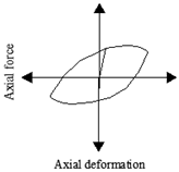
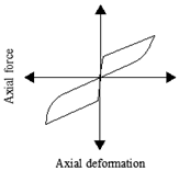
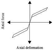
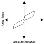
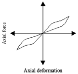
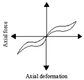
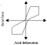
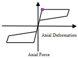
| Study | Main Findings | Sample Hysteresis |
|---|---|---|
| Elghazouli [26] |
|  |
| Shaback and Brown [3] |
|  |
| Elghazouli [5] |
|  |
| Goggins et al. [40] |
|  |
| Tremblay et al. [44] |
|  |
| Palmer et al. [2] |
|  |
| Study | Type | Main Features | Schematic Hysteresis Response |
|---|---|---|---|
| L.-H. Xu et al. [50] and L. H. Xu et al. [51] | Experimental |
|  |
| Chou and Chen [52] | Experimental and Numerical |
|  |
| Baiguera et al. [53] | Numerical |
|  |
| Zhou et al. [54] and Xie et al. [55] | Experimental and Numerical |
|  |
| C. Qiu and Zhu [56] and C.-X. Qiu and Zhu [57] | Experimental and Numerical |
|  |
| Araki et al. [48] | Experimental and Numerical |
|  |
| Choi et al. [58] | Experimental |
|  |
| Speicher et al. [59] | Experimental and Analytical |
|  |
| Haque and Alam [9] | Numerical |
|  |
| Wu and Phillips [60] | Analytical and Numerical |
|  |
| Issa and Alam [61] | Experimental and Numerical |
|  |
| Issa and Alam [62] | Experimental and Numerical |
|  |
| Qiu and Du [63] | Analytical and Numerical |
|  |
| Kari et al. [64] | Numerical |
|  |
| Zareie et al. [65] | Numerical |
|  |
| Atasever et al. [66] | Experimental and Numerical |
|  |
| Yousef-beik et al. [67] | Experimental and Numerical |
|  |
| Wang et al. [49] | Experimental and Numerical |
|  |
| Zhang et al. [68] | Experimental |
|  |
| Issa et al. [69] | Closed-Loop Dynamic Testing |
|  |
| Issa et al. [70] | Experimental and Numerical |
|  |
Disclaimer/Publisher’s Note: The statements, opinions and data contained in all publications are solely those of the individual author(s) and contributor(s) and not of MDPI and/or the editor(s). MDPI and/or the editor(s) disclaim responsibility for any injury to people or property resulting from any ideas, methods, instructions or products referred to in the content. |
© 2024 by the authors. Licensee MDPI, Basel, Switzerland. This article is an open access article distributed under the terms and conditions of the Creative Commons Attribution (CC BY) license (https://creativecommons.org/licenses/by/4.0/).
Share and Cite
Issa, A.; Stephen, S.; Mwafy, A. Unveiling the Seismic Performance of Concentrically Braced Steel Frames: A Comprehensive Review. Sustainability 2024, 16, 427. https://doi.org/10.3390/su16010427
Issa A, Stephen S, Mwafy A. Unveiling the Seismic Performance of Concentrically Braced Steel Frames: A Comprehensive Review. Sustainability. 2024; 16(1):427. https://doi.org/10.3390/su16010427
Chicago/Turabian StyleIssa, Anas, Steffi Stephen, and Aman Mwafy. 2024. "Unveiling the Seismic Performance of Concentrically Braced Steel Frames: A Comprehensive Review" Sustainability 16, no. 1: 427. https://doi.org/10.3390/su16010427
APA StyleIssa, A., Stephen, S., & Mwafy, A. (2024). Unveiling the Seismic Performance of Concentrically Braced Steel Frames: A Comprehensive Review. Sustainability, 16(1), 427. https://doi.org/10.3390/su16010427