Article

The Design and Application of Microgrid Supervisory System for Commercial Buildings Considering Dynamic Converter Efficiency

1
School of Artificial Intelligence, Beijing Technology and Business University, Beijing 100048, China
2
Department of Energy Internet Research, State Grid Energy Research Institute, Beijing 102209, China
*
Author to whom correspondence should be addressed.
Sustainability 2023, 15(8), 6413; https://doi.org/10.3390/su15086413
Submission received: 16 March 2023 / Revised: 2 April 2023 / Accepted: 5 April 2023 / Published: 10 April 2023

Abstract

:
This paper presents a supervisory system that considers converter efficiency for local microgrids of commercial buildings to solve the uncertainty problem of the sources and loads while also optimizing local microgrid operating costs and maintaining power supply quality for commercial buildings. The supervisory system includes an energy management layer and a power management layer. In the energy management layer, a long-term optimization approach is used to reduce the operating costs by considering the dynamic converter efficiency. In the power management layer, a real-time power optimization method is structured to deal with the uncertainty problem of the sources and loads, and to ensure that the direct current bus power is balanced while also guaranteeing the power quality by considering the dynamic converter efficiency. Four cases are proposed for the supervisory system, and these cases are simulated in MATLAB/Simulink under three typical weather conditions: cloud, sunshine, and rain. The comparison of simulation results for cases 1 and 2 illustrates the impact of converter efficiency on energy coordination in microgrids. The simulation results of cases 3 and 4 verify that the performance—in terms of the power supply quality and the operating costs—of the proposed microgrid supervisory system considering dynamic converter efficiency outperforms that of the microgrid supervisory system considering fixed converter efficiency.

1. Introduction

1.1. Context

The world is striving to achieve net-zero greenhouse gas emissions by 2050 [1]. Renewable energy sources such as photovoltaic (PV) and wind energy, with characteristics that include environmental friendliness, sustainability, low carbon generation, and potential for energy savings [2,3], provide an effective boost to the net-zero emission aims and are showing explosive growth at unprecedented speeds [4]; however, this poses severe challenges for power regulation and control of the power grids [5,6,7,8,9].
A microgrid is a small power generation and distribution system that comprises distributed power sources, energy storage systems, energy conversion devices, loads, supervisory systems, protection devices, and other components that can promote integration and consumption of local renewable energy, ensure the reliability of the power supply, and optimize grid operation [10,11,12,13]. Microgrids can be viewed from a triple perspective in terms of energy, economy, and society. From the energy perspective, the proposal of a microgrid is intended to realize flexible and efficient application of distributed power and to solve the problem of grid connection of large numbers and various forms of distributed power generation sources [14,15]. From an economic viewpoint, the development and extension of microgrids can form multi-microgrid architectures [16,17], can fully promote large-scale access for distributed power sources and renewable energy sources, and can realise a highly reliable supply composed of multiple energy forms [18,19], thus providing an economical and effective way to transition from conventional power grids to smart grids [20,21,22]. From the social perspective, microgrids represent the concrete embodiment of a green and low-carbon energy production method and lifestyle, and they provide effective assistance for ecological and environmental protection [23,24].
However, the intermittency and uncertainty of renewable energy sources and the complexity of the load demand pose serious challenges for energy management in microgrids [25,26]. Many researchers have been working on energy management approaches for microgrids. Cheng et al. [27] proposed a novel multi-time-scale dynamic robust optimal scheduling strategy to deal with the performance uncertainties of renewable energy sources and the variations in load demands, while also effectively reducing the microgrid’s operating cost and improving the robustness of its coordinated operation. Dashtaki et al. [28] proposed an energy management system to determine the balance required between the total electricity generated and the associated demand. Zia et al. [29] proposed a two-stage supervisory energy management system for optimal operation of a PV/wind/tidal islanded direct current (DC) microgrid that used one-time communication to avoid excessive use of the communication bandwidth during real-time operation. Ferahtia et al. [30] proposed an optimal energy management strategy that considered various techno-economic challenges, including power quality, system stability, fuel consumption, and system efficiency. In [31], a load-shifting mechanism was considered. Chen et al. [32] proposed a decision-making strategy to consider the uncertainties involved in both use of renewable energy sources and the load demand. Erol and Başaran Filik [33] proposed a Stackelberg game approach to reduce the dependency of microgrids on the utility grid (UG) by considering the flexibility of the prosumers. Alabdullah and Abido [34] proposed a deep reinforcement learning-based approach to enable optimal management of the different energy resources by considering the stochastic behaviour of the load-generation profile and the pricing signals to achieve optimal cost-effective actions. In [35], a mimosa pudica-based energy management scheme was proposed to reduce production overheads. In [36], an energy management strategy to maintain stable and reliable operation of a microgrid was proposed. Guo et al. [37] proposed a robust optimization algorithm that considered the uncertainty of the renewable energy sources and industrial loads. The research above on energy management for microgrids mainly focuses on the uncertainties of the renewable energy sources and the loads, the supply–demand balance, the excessive pressure being placed on the power grids, and the reliability of the local power supply, but ignores the problems caused by converter efficiency.

1.2. State-of-the-Art

Microgrids integrate large numbers of bidirectional converters, which will cause problems in terms of energy efficiency, power stability, operating costs, and other factors. These problems can be resolved in two ways. The first way is to mitigate the problems using hardware, i.e., by improving the materials or the topology of the converters to reduce their negative impact on the microgrid. By replacing the clamp-insulated gate bipolar transistor (IGBT) of the SiC metal-oxide-semiconductor field-effect transistor (MOSFET) in the converter, the switching losses can be reduced, and thus the system efficiency and the harmonic performance will be improved. Van den Broeck et al. [38] evaluated the power conversion efficiency of a three-level buck DCDC converter when operating in unbalanced bipolar DC microgrids. A modelling and design topology for a bidirectional DCDC converter was developed which improved the efficiency of the converter, enabled efficient usage of renewable energy sources, and reduced the switching losses [39]. Rai et al. [40] proposed the use of converter arrays in place of centralized converters to improve the converter efficiency in a DC microgrid. In terms of efficiency, two-level rectifiers generally offer higher operating efficiency than modular multilevel converters because they have lower switching and conduction losses. Diode rectifiers have the highest efficiency because they have no switching losses or power losses in their gate driver circuits. The second method involves solving the problems using software algorithms, i.e., by considering the converter efficiency in energy management algorithms, and an appropriate energy management strategy can improve the performance of a microgrid by compensating for the power of the converter [39,41,42,43,44,45,46]. With the aim of promoting the transmission efficiency of the converters, a deep reinforcement learning optimization scheme with a triple-phase shift was proposed [41]. A higher switching frequency will lead to higher switching losses, and thus reduction of the switching frequency represents a fundamental method to improve the converter efficiency [44,45]. A distributed optimal control algorithm was also presented for DC microgrids to minimize operating losses, including converter losses and distribution losses [47]. However, the energy optimization period was very short. In [43], a multi-objective optimization dispatch method was proposed for microgrid energy management, which considered the power losses of converters by defining the converter efficiency as 98%. Because of the high cost issue associated with advanced converters, this paper preferred a software approach to alleviate the problems caused by the converter. However, the efficiency of the converters that were commonly used in the cases above is fixed.
The converter efficiency changes in real time with the voltage, current, time, and environmental conditions, and thus it is necessary to consider the dynamic converter efficiency to improve the effectiveness of microgrid multi-time-scale power and energy management. Pachanapan [48] presented a dynamic model of the grid-tied inverters used in battery and PV systems. Kong and Nian [49] proposed a transient modelling method for DC microgrids that considered the control effects of different DC/AC and DC/DC converters; their results showed that the proposed method can not only improve the accuracy of transient analysis of the DC microgrids, but can also enhance the calculation efficiency. To mitigate the effects of multiple uncertainties and realize economical operation of an AC/DC hybrid microgrid, a temporally coordinated energy management strategy was proposed for the AC/DC hybrid microgrid which considered the dynamic conversion efficiency of the bidirectional AC/DC converter in [50]. However, this strategy only considered the dynamic efficiency of a single converter connecting the AC and DC buses, and other converters, including the converter connecting the PV sources and the DC bus and the converter connecting the wind turbine with the AC bus, were ignored. Both AC/DC converters and DC/DC converters are present in the microgrid, and the advantages of the energy management system can only be exploited fully by considering the efficiency characteristics of multiple converters.

1.3. Paper Aim

Microgrids have the capacity to be isolated. While conventional microgrids emphasize their role in improving local energy independence and resilience, commercial building microgrids must typically maintain a power supply for at least the time required to cope with UG outages without damaging the system, and in some cases, these microgrids may even be able to power the system indefinitely [51,52]. This paper is dedicated to a study of a supervisory system for commercial building microgrids with multiple sources, multiple storage types, and a series of interruptible appliances, for consideration as part of long-term energy planning, while also maintaining the real-time supply–demand balance, with high converter efficiency. The microgrid topology of a commercial building, as illustrated in Figure 1, comprises roof-top PV sources, the UG, a battery storage (BS) system, a diesel generator (DG), a supercapacitor (SC), the commercial building itself, and five bidirectional converters. The proposed supervisory system uses a long-term optimization approach to deal with the uncertainties in the PV power generation and the load demand. Errors in the long-term optimization process can be rescheduled at the power management level of the supervisory system.

1.4. Contribution

Overall, based on the facts discussed above, the main contributions of this study can be summarized as follows:
  • In this study, a microgrid-based smart power supply system that has multiple sources and multiple storage types is constructed to ensure reliable operation and handling of a commercial building’s load demand. In the commercial building microgrid, local PV sources provide green energy; controllable sources, represented by the BS system and the UG, are used to balance the power of the DC bus. The DG is used as a long-term backup source, and the SC is used to support the power deficiency that occurs while the DG starts up.
  • A two-layer microgrid supervisory system comprising an energy management layer and a power management layer is designed in this paper to consider long-term energy planning while also maintaining the real-time supply–demand balance. The supervisory system takes the dynamic characteristics of the efficiency of the bidirectional converter fully into account, and observes the physical constraints of the microgrid components.
  • Four cases are analyzed comprehensively and compared under three different weather conditions for the supervisory system. Case 1, in which the converters are idealized to realize an ideal conversion efficiency of 100%, provides a baseline. Simulations show that case 3, which involves a dynamic converter efficiency model, is effective in reducing the operating costs and improving the power supply quality of the commercial building microgrid.
The remainder of this paper is organized as follows. Section 2 describes the DC microgrid and the converter efficiency modelling process. Section 3 presents the proposed supervisory system, which comprises an energy management level and a power management level. The supervisory system is then validated in Section 4. Finally, conclusions are drawn and directions for future work are discussed in Section 5.

2. DC Microgrid

The commercial building microgrid with a DC bus can be structured as shown in Figure 1, with a supervisory system and several physical components. All components are connected to the common DC bus of the microgrid via power converters. The loads of the commercial building, which include the emergency lighting, a stair lift, multiple personal computers, multiple printers, and other electrical equipment, are assumed to be connected directly to the DC bus. The roof-top PV sources, a BS system, the UG, a DG, an SC, and five converters, including a DC/DC converter and a DC/AC converter consisting of an IGBT, are proposed to support the loads of the commercial building microgrid.
The PV sources consist of several PV panels, and the power generated supplies the load demand directly through the DC bus for the maximal renewable energy usage rate. If the power generated by the PV sources cannot fully support the DC loads, the BS and the UG will then supply these loads. If the PV sources, the BS, and the UG cannot provide sufficient power for the loads, the noncritical loads will then be shed, including the heating, ventilation, air conditioning, and water heater loads. If the critical loads are at risk of being shed, the DG would then start up as a back-up source. If there is PV power in excess of that required to support the loads, the BS and the UG would absorb this excess PV power. If the BS and the UG cannot absorb the excess power, the PV will then be shed to maintain the power balance of the DC bus. The power converter is as the key component that enables power transfer between these components, and thus the conversion efficiency of the power converters has a significant impact on the energy and power management processes in the supervisory system. However, the conversion efficiency of the power converters is constantly varying, and thus accurate modelling of the conversion efficiency of these converters is essential for energy and power management in the commercial building microgrid.

2.1. Microgrid Modelling

To maintain the power balance and keep the DC bus voltage stable, a power balance constraint is used:
p P V ( t ) + p D G ( t ) p C V _ L O S S ( t ) = p L ( t ) + p B S _ C H ( t ) p B S _ D C H ( t ) + p S C _ C H ( t ) p S C _ D C H ( t ) + p U G _ I ( t ) p U G _ S ( t ) ,
where p P V ( t ) is the power of the PV sources at time step t ; p D G ( t ) is the power supplied by the DG; p C V _ L O S S ( t ) represents the total loss of the converters; p L ( t ) is the load power; p B S _ C H ( t ) and p B S _ D C H ( t ) are positive variables that denote the BS charging and discharging powers, respectively; p S C _ C H ( t ) and p S C _ D C H ( t ) are the SC charging and discharging powers; and the positive variables p U G _ S ( t ) and p U G _ I ( t ) are the UG powers supplied to and injected from the commercial building microgrid, respectively.
For the PV sources, p P V ( t ) is restrained to the maximum PV power p P V _ M P P T ( t ) under the current weather conditions at the time step t , which is expressed as follows:
p P V ( t ) = p P V _ M P P T ( t ) p P V _ S ( t ) ,
where p P V _ S ( t ) is the PV shedding power.
The load demand power p L _ D ( t ) comprises the noncritical load p L _ D _ N R ( t ) and the critical load p L _ D _ C R ( t ) ; p L _ S _ C R ( t ) is normally zero, and represents critical loads operating in an orderly manner; p L _ D _ C R ( t ) directly reflects the microgrid’s ability to maintain the key operations that must be kept running during a power outage. The load constraints are described as follows:
p L ( t ) = p L _ D ( t ) p L _ S ( t ) p L _ D ( t ) = p L _ D _ N R ( t ) + p L _ D _ C R ( t ) p L _ S ( t ) = p L _ S _ N R ( t ) + p L _ S _ C R ( t ) p L _ D _ C R ( t ) = k L _ C R ( t ) p L _ D ( t ) ,   k L _ C R [ 0 % , 100 % ] ,
where p L ( t ) is limited by the load demand power p L _ D ( t ) at the time instant t , and p L _ D _ C R ( t ) is calculated by multiplying the pre-defined critical load coefficients k L _ C R ( t ) and p L _ D ( t ) .
Because of its low cost and high recycling rate, the BS is organized using a set of lead-acid batteries, which are commonly used in small-scale microgrids. To maintain normal BS system operation, the following constraints are given:
0 p B S _ C H ( t ) p B S _ C H M A X ( t ) 0 p B S _ D C H ( t ) p B S _ D C H M A X ( t ) p B S ( t ) = p B S _ C H ( t ) p B S _ D C H ( t ) s o c B S ( t ) = s o c B S ( t Δ t ) + p B S ( t ) Δ t V B S _ R C R E F S O C B S M I N s o c B S ( t ) S O C B S M A X ,
where the charging and discharging powers of the BS are limited to its maximal charging and discharging powers p B S _ C H M A X ( t ) and p B S _ D C H M A X ( t ) , respectively, at time instant t . Each cell in the BS system is assumed to exhibit one of the two behaviours per time step t , i.e., charging or discharging, and thus the BS power p B S ( t ) is defined as the difference between p B S _ C H M A X ( t ) and p B S _ D C H M A X ( t ) . The state of charge (SOC) of the BS at time instant t , denoted by s o c B S ( t ) , is assumed to be the accumulated p B S ( t ) , V B S _ R is the BS’s rated voltage, and C R E F is the BS’s capacity. To mitigate the aging of the BS, overcharging and over-discharging of the BS should be avoided, and thus s o c B S ( t ) is limited to its maximal value S O C B S M A X and its minimal value S O C B S M I N .
The microgrid is designed to operate within an on-grid/off-grid model, and the UG can exchange power and information with the microgrid. The UG is assumed to receive the following constraints in real time:
0 p U G _ I ( t ) p U G _ I M A X ( t ) 0 p U G _ S ( t ) p U G _ S M A X ( t ) p U G ( t ) = p U G _ I ( t ) p U G _ S ( t ) ,
where p U G _ I ( t ) and p U G _ S ( t ) are bound to p U G _ I M A X ( t ) and p U G _ S M A X ( t ) , respectively, and the UG power p U G ( t ) is defined as the difference between p U G _ I M A X ( t ) and p U G _ S M A X ( t ) .
The DG is used as a long-term backup source for the DC microgrid while respecting the following constraints:
0 p D G ( t ) p D G _ O N M A X ( t ) ,
where p D G ( t ) is limited by the DG’s maximal output power p D G _ O N M A X ( t ) . Because the DG start-up stage represents slow dynamic behaviour, an SC is suggested to compensate for the power balance during the DG’s start-up period, because of its fast response and high power density [53]. The relevant constraints are given as follows:
0 p S C _ C H ( t ) p S C _ C H M A X ( t ) 0 p S C _ D C H ( t ) p S C _ D C H M A X ( t ) p S C ( t ) = p S C _ C H ( t ) p S C _ D C H ( t ) S O C S C M I N s o c B S ( t ) S O C S C M A X E S C ( t ) = C S C v S C 2 ( t ) 2 s o c S C ( t ) = E S C ( t ) E S C _ R a t e d = v S C ( t ) v S C _ R a t e d 100 % ,
where the SC energy E S C ( t ) at time step t is calculated using the SC capacitance C S C ( t ) and the SC voltage v S C ( t ) ; therefore, the calculated SOC of the SC, denoted by s o c S C ( t ) , translates to the proportion of v S C ( t ) to the SC’s rated voltage v S C _ R a t e d ( t ) .

2.2. Converter Efficiency Modelling

The converters used in the commercial building microgrid are DC/DC converters and DC/AC converters, as shown in Figure 1. These converters are formed by connecting the IGBT to the surrounding inductors and capacitors directly [46,54,55]. The converter has an input port and an output port, and the ability to transfer power bidirectionally between physical components and the DC bus. Because of the limitations of the microgrid topology, the measured variables, including the voltage and current, can only be measured on the source side.
The converter efficiency ξ ( t ) can be calculated using the power on the source side p s ( t ) and the power loss p l o s s _ s u m ( t ) when the power flow is from the sources to the DC bus, as shown in Equation (8):
ξ ( t ) = p s ( t ) p l o s s _ s u m ( t ) p s ( t )
When the power flow is directed from the DC bus to the sources, ξ ( t ) can be calculated using Equation (9):
ξ ( t ) = p s ( t ) p s ( t ) + p l o s s _ s u m ( t )
To simplify the mathematical modelling of the converters while also highlighting the impact of the conversion efficiency on the commercial building microgrid, the power loss compensation circuit, which may include dedicated buffer circuits, phase-shifted full-bridge soft switches, and auxiliary circuits, is not taken into account. The power losses of the converters include the losses of the semiconductors, the losses of the passive components, and the losses of the control circuits [43,56]. The losses of the semiconductors comprise the conduction loss and the switching loss. The control circuit losses can be neglected because they are relatively small when compared with the losses mentioned previously.
A boost/buck converter is applied as the DC/DC converter in the commercial building microgrid. Using boost/buck converters as an example, a converter power loss model is formulated as shown by Equations (10) and (11).
p l o s s _ s u m t = p c o n d t + p c o m t + p L t p c o n d t = p c o n d T t + p c o n d D t p c o n d T t = V C E 0 i s t d t + r C E i s 2 t d t p c o n d D t = V F 0 i s t 1 d t + r F i s 2 t 1 d t p c o m t = p c o m T t + p c o m D t p c o m T t = E o n i s t + E o f f i s t V c c t U n f p c o m D t = 1 2 f V c c t Q r r p L = r L i s 2 t
where p l o s s _ s u m donates the sum of the converter power losses including the conduction loss p c o n d , the switching loss p c o m , and the power loss in the inductance p L . p c o n d includes the transistor conduction loss p c o n d T and the diode conduction loss p c o n d D , V C E 0 is the threshold voltage for the voltage drop between the collector and the emitter of the transistor, i s is the source side current, r C E is the resistance between the collector and the emitter, which is equivalent to the resistance sum in the transistor, and d is the duty cycle of the transistor turn-on. V F 0 is the threshold voltage for the diode forward voltage drop, and r F is the resistance of the diode. ( 1 d ) represents the duty cycle of the diode turn-on, p c o m includes the transistor switching loss p c o m T and the diode switching loss p c o m D . E o n / E o f f is the switch-on/off loss, V c c is the direct voltage applied to the diode when opening the circuit, U n is the nominal voltage of the transistor, and f is the switching frequency. Q r r is the reverse recovery charge, r L is the internal resistance of the inductor coil.
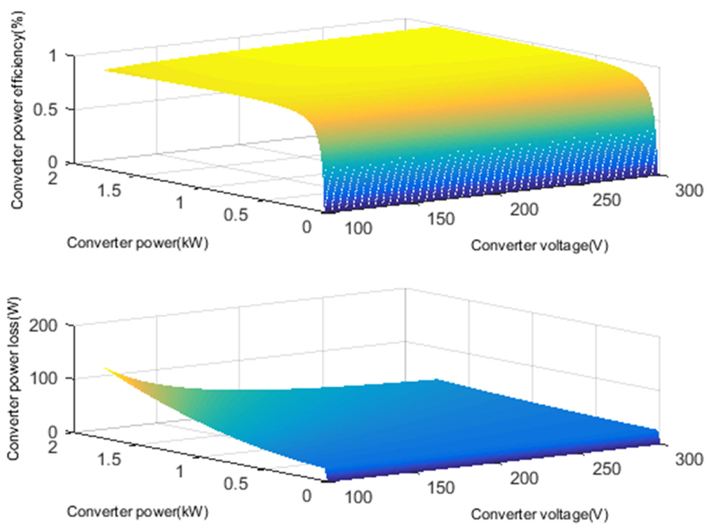
According to Equations (8)–(10), the conversion efficiency of the converter is not a fixed value, and this efficiency varies with the operating voltage and the transmitted power of the converter. An example of the converter efficiency and the transmission power loss for a PV boost converter is shown in Figure 2. When the converter is working in the low transmitted power and low voltage state, the converter has a low conversion efficiency and suffers high power losses. Therefore, the conversion efficiency and the power losses are influenced by both the operating voltage and the transmitted power. Five power converters are included in our study, which will lead to increased transmission power losses and affect the operation of the microgrid. Therefore, the converter loss model should be considered within the supervisory system of the commercial building microgrid.
Because i s and V c c are proportional to the power on the source side p s , p l o s s _ s u m can also be formulated approximately as Equation (11), where a s , b s , and c s are polynomial coefficients.
p l o s s _ s u m ( t ) = a s p s 2 ( t ) + b s p s ( t ) + c s

3. Microgrid Supervisory System Design

The multiple power generation sources, storage systems, and loads involved mean that the energy management of a commercial building microgrid is complex when operating under uncertain conditions, wherein the renewable energy sources and the load demand are affected separately by the weather conditions and the various user behaviours. Accordingly, a supervisory system that considers the energy and power management comprehensively should be established to handle the discrete events of the loads and continuous regulation of the commercial building microgrid.
The microgrid supervisory system has an inherent ability to handle the balance between supply and demand intelligently, based on the fact that the system is complex and that it therefore needs to couple the user-defined discrete data with the continuous data on the source side, weather data, and other data sources. The microgrid supervisory system is designed as shown in Figure 3, including the energy management layer and power management layer. The objective of the energy management layer is to optimize the cost of the energy by dispatching the sources, storage, and load demands under the constraints of the microgrid, while considering the metadata, including the PV and load demand prediction data. The core aim of the energy management layer is long-term optimization. The goal of the power management layer is to eliminate any decision-making errors from the previous layer, while also controlling the power flow in real time to achieve power balancing. The core of the power management layer is a real-time power management strategy and a component controller. Both of these layers consider the converter loss model.

3.1. Energy Management Layer

The objective of the energy management layer is to minimize the operating cost of the microgrid C t o t a l D A O ( t ) over a time horizon H , as shown in Equation (12), while considering the constraints of the components in Equations (1)–(7), (11), and (19):
C T O T A L D A O = m i n t H C t o t a l D A O ( t )
C t o t a l D A O ( t ) is composed of the BS aging cost C B S ( t ) , the UG power cost C U G ( t ) , the DG power cost C D G ( t ) , and the SC aging cost C S C ( t ) , and is given as:
C t o t a l D A O ( t ) = C B S ( t ) + C U G ( t ) + C D G ( t ) + C S C ( t )
The BS aging cost consists of the BS charging and discharging aging costs, which are expressed as C B S _ C H ( t ) and C B S _ D C H ( t ) , respectively. The BS charging and discharging states are constrained by the coefficients x B S _ C H ( t ) and x B S _ D C H ( t ) , respectively, as follows:
C B S ( t ) = C B S _ C H ( t ) + C B S _ D C H ( t ) C B S _ C H ( t ) = c B S _ A g i n g x B S _ C H ( t ) p B S _ C H ( t ) Δ t C B S _ D C H ( t ) = c B S _ A g i n g x B S _ D C H ( t ) p B S _ D C H ( t ) Δ t x B S _ C H ( t ) + x B S _ D C H ( t ) 1 x B S _ C H ( t ) , x B S _ D C H ( t ) { 0 , 1 } ,
where C B S _ C H ( t ) and c B S _ A g i n g are affected by the BS charging and discharging aging tariffs c B S _ A g i n g and c B S _ A g i n g , respectively; x B S _ C H ( t ) and x B S _ D C H ( t ) are set to be 0 or 1 to indicate that the BS is charging or discharging, respectively, and the sum of x B S _ C H ( t ) and x B S _ D C H ( t ) is less than or equal to 1.
The SC aging cost in Equation (15) has the same formulation that was used for the BS.
C S C ( t ) = C S C _ C H ( t ) + C S C _ D C H ( t ) C S C _ C H ( t ) = c S C _ A g i n g x S C _ C H ( t ) p S C _ C H ( t ) Δ t C S C _ D C H ( t ) = c S C _ A g i n g x S C _ D C H ( t ) p S C _ D C H ( t ) Δ t x S C _ C H ( t ) + x S C _ D C H ( t ) 1 x S C _ C H ( t ) , x S C _ D C H ( t ) { 0 , 1 } ,
The UG cost considers the costs of selling and buying UG electricity to and from the microgrid, as denoted by C U G _ S ( t ) and C U G _ I ( t ) , respectively, as:
C U G ( t ) = C U G _ S ( t ) C U G _ I ( t ) C U G _ S ( t ) = c U G _ S ( t ) x U G _ S ( t ) p U G _ S ( t ) Δ t C U G _ I ( t ) = c U G _ I ( t ) x U G _ I ( t ) p U G _ I ( t ) Δ t x U G _ I ( t ) + x U G _ S ( t ) 1 x U G _ I ( t ) , x U G _ S ( t ) { 0 , 1 } ,
where C U G _ S ( t ) and C U G _ I ( t ) are calculated using the tariffs for selling and buying UG electricity c U G _ S ( t ) and c U G _ I ( t ) , and the selling and buying are constrained by the coefficients x U G _ S ( t ) and x U G _ I ( t ) , respectively.
The DG cost is composed of the DG fuel cost C D G _ F u e l ( t ) and the DG aging cost C D G _ A g i n g ( t ) . The DG fuel cost is calculated using the DG fuel tariff c D G _ F u e l ( t ) and p D G ( t ) , and the DG aging cost is calculated using the DG aging tariff c D G _ A g i n g ( t ) and the DG operating time, as follows:
C D G ( t i ) = C D G _ F u e l ( t ) + C D G _ A g i n g ( t ) C D G _ F u e l ( t ) = c D G _ F u e l ( t ) p D G ( t ) Δ t C D G _ A g i n g ( t ) = c D G _ A g i n g Δ t ,
In the daytime, the UG and the BS are restricted from exchanging power with each other to prevent the BS from arbitraging only from the UG and ignoring the local load demand; this is represented by the following constraint:
s i g n ( p U G ( t ) ) = s i g n   ( p B S ( t ) ) ,
The modelling of the energy management problem presented above can ensure economical microgrid system operation, but the utilization of the renewable energy and that of the reliable power supply for the load demand are not taken into account; therefore, the objective of the energy management problem in Equation (12) is reformulated with a PV-shedding punishment component and a load-shedding punishment component as:
C T O T A L D A O = m i n ( t H C t o t a l D A O ( t ) + P U P V ( t ) + P U L ( t ) ) ,
where the PV and load-shedding punishment components are denoted by P U P V ( t ) and P U L ( t ) , respectively.
P U P V ( t ) is calculated using:
P U P V ( t ) = p u P V _ P N p P V _ S ( t ) Δ t ,
where p u P V _ P N is the PV-shedding punishment coefficient.
The load-shedding punishment component includes the noncritical load-shedding punishment component P U L _ N R ( t ) and the critical load punishment component P U L _ C R ( t ) , and the punishment coefficients for noncritical and critical load shedding are p u L _ P N _ N R ( t ) and p u L _ P N _ C R ( t ) , respectively, as shown in Equation (2). In principle, p u L _ P N _ C R is infinity, because it may be related to human life and to huge economic losses, e.g., to the equipment in a hospital and to the production line of an important factory, respectively.
P U L ( t ) = P U L _ N R ( t ) + P U L _ C R ( t ) P U L _ N R ( t ) = p u L _ P N _ N R p L _ S _ N R ( t ) Δ t P U L _ C R ( t ) = p u L _ P N _ C R p L _ S _ C R ( t ) Δ t ,

3.2. Power Management Layer

The uncertainties of the PV sources and the loads result in prediction errors that mean that the energy management layer cannot be used directly to control the physical components of the DC microgrid. Therefore, the power management layer is proposed as an intermediate layer to reschedule the power flow and maintain power balances in real time, while respecting all the components’ constraints.
In the power management layer, the results from the energy management layer are converted into two optimization coefficients, k D and k D G , as given in Equation (22):
k D = p B S D A O / ( p B S D A O + p U G D A O ) k D G = 1 i f   p D G D A O > 0 0 o t h e r s ,
where k D is calculated as the proportion of the powers allocated by the BS and the UG from the energy management layer, and k D G indicates whether the DG is set to be on or off based on the results from the energy management layer.
The power management layer operates in real time to dispatch the power flow based on the current state of the microgrid; the problem formulation is given in Equations (23) and (24), with the constraints given in Equations (2)–(7):
C T O T A L I N D = st . 1 : min ( k D · p P V R T p L R T p C V _ L O S S p B S + 1 k D · p P V R T p L R T p C V _ L O S S p U G ) if   k D G = 0   and   w S C = 0 st . 2 : min ( p B S _ D C H M A X + p U G _ S M A X + p P V R T p L R T p S C _ C H p C V _ L O S S ) if   k D G = 0   and   w S C = 1 st . 3 : min ( w D G _ 1 · p S C _ D C H + p P V R T p L R T p C V _ L O S S ) if   k D G = 1   and   w D G _ 1 = 1 st . 4 : min ( w D G _ 2 · p P V R T + p D G p S C _ C H p L R T p C V _ L O S S ) if   k D G = 1   and   w D G _ 2 = 1 st . 5 : min ( w D G _ 3 · p P V R T + p D G p B S _ C H p L R T p C V _ L O S S ) if   k D G = 1   and   w D G _ 3 = 1 ,
where the optimization objective of C T O T A L I N D is to minimize the power balance errors in real time. The microgrid operating states include five power balance states. The first state is that in which the microgrid operation relies on a controllable BS and UG to balance the power differences between the PV and the load demand; the second state is that in which the microgrid charges the SC to ensure that the SC retains its capability of supporting the DG start-up while also maintaining the power balance set by the coefficient w S C in Equation (24), and the third state, fourth state, and fifth state aim to maintain the power balance when the DG is switched on, with the three stages being selected based on the three coefficients w D G _ 1 , w D G _ 2 , and w D G _ 3 , respectively, in Equation (24).
w S C = B o o l e a n ( s o c s c S O C s c _ min ) w D G _ 1 = ( 0 < t c o u n t _ o n T D G _ 1 ) w D G _ 2 = ( T D G _ 1 < t c o u n t _ o n T D G _ 2 ) w D G _ 3 = ( T D G _ 2 < t c o u n t _ o n T D G _ 3 )
where w S C is the coefficient to be set if the SC needs to be charged; w D G _ 1 is intended to select the first stage when the DG is on, where the SC is used to compensate for the power deficiency when the DG is turned on [53]; because of the high power tariff when the DG is turned on, the DG is set to operate for a long period to charge both the SC and the BS to reduce the cost of frequent DG start-ups. w D G _ 2 is used to set the second stage when the DG is switched on, where the DG can provide supporting power to charge the SC and maintain the microgrid’s power balance. Finally, w D G _ 3 is used to set the third stage when the DG is switched on, where the DG can output power to charge the BS while again maintaining the microgrid power balance.

4. Simulation Results and Analyses

The proposed microgrid supervisory system was programmed in MATLAB/Simulink, and the optimization problem was solved using CPLEX software [57]. The hardware device used to perform the simulation was a desktop computer with an Intel Core i7 2.6 GHz central processing unit (CPU) and 16 GB of random access memory (RAM).

4.1. Simulation Cases and Parameters

The commercial microgrid model and the microgrid supervisory system that were presented in Section 2 and Section 3 were applied in a simulation. The simulation parameters listed in Table 1 are based on an existing experimental building-integrated microgrid system equipped with 1.75 kWh of roof-top PV arrays, a 12 V/33 Ah battery with 1 kW charging and discharging power limits, a point of common coupling connected to the UG with a variable power limit taken from the upper distribution network, a voltage of UG which complies with the Council Directive 93/68/EEC, a DG system with a 1.5 kW output power limit, an SC with 1.5 kW charging and discharging power limits, and a building load demand comprising a series of controllable electrical appliances. Because the microgrid system operates in the low power range, the curve of converter power loss versus converter transmitted power can be approximated as a linear function, and the approximate parameters, a and b, are shown in Table 1.
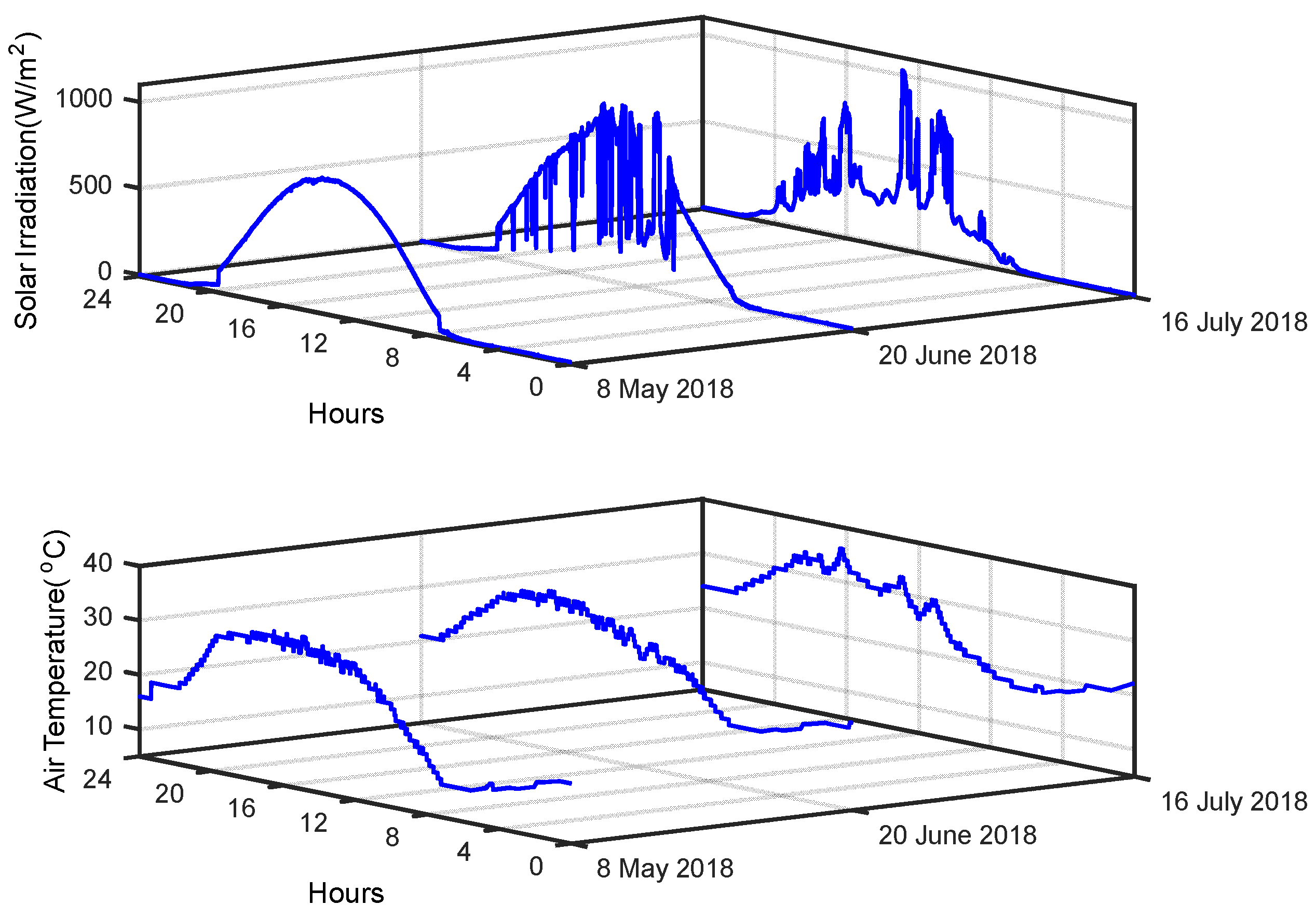
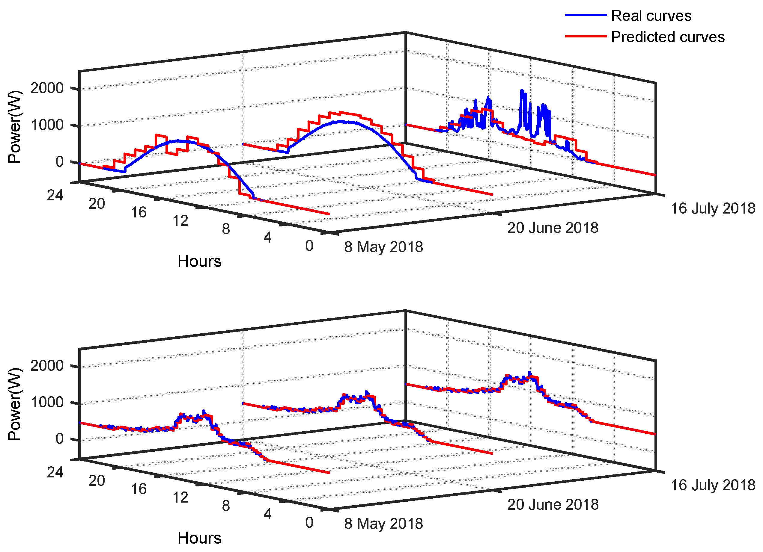
The operation of the microgrid must account for the effects of several uncertain factors: e.g., weather conditions, load demand, UG electricity prices, and power limits. Therefore, to verify the microgrid’s operating performance fully, a real weather dataset that included solar irradiation and temperature data was collected to perform a system simulation, as illustrated in Figure 4. The dataset represents three typical weather conditions, as recorded on 20 June (cloud), 8 May (sunshine), and 16 July (rain) in 2018 in France. The profiles of the PV power, the scaled-down load demand of the commercial buildings, and their predicted characteristics are shown in Figure 5.
In Table 1, k L _ C R is set at 100% in the power supply valley and at 80% at all other times. The initial SOC of the BS, denoted by S O C B S _ 0 , was set at 50%, and s o c B S was limited to the range from 20–80%. p U G _ I M A X / p U G _ S M A X was set at 600 W in the power supply valley and at 200 W at all other times. The initial SOC of the SC, denoted by S O C S C _ 0 , was 75%, and S O C s c _ min was set at 45% to maintain the minimal energy required to support the DG start-up process. Based on consideration of the power conversion efficiency between the microgrid and the UG, the reference voltage of the common DC bus v D C * was set at 400 V.
The tariff for each physical component was predefined in Table 1 using a selected pricing mechanism, where the high load-shedding punishment tariff was set at 10 EUR/kWh, the PV power-shedding punishment tariff was set at 5 EUR/kWh, and the UG power tariff was set at 0.01 EUR/kWh in the power supply valley, at 0.7 EUR/kWh during the power supply peak, and at 0.1 EUR/kWh during the power supply shoulder, using the TOU method [35]. In addition, the BS power tariff was set considerably lower at 0.07 EUR/kWh, the BS power tariff was set at 0.3 EUR/kWh, the DG power tariff was contrastingly set high at 1.2 EUR/kWh because of the high cost of the diesel fuel, and the DG operation and maintenance tariff was set at 0.63 EUR/kWh [58].
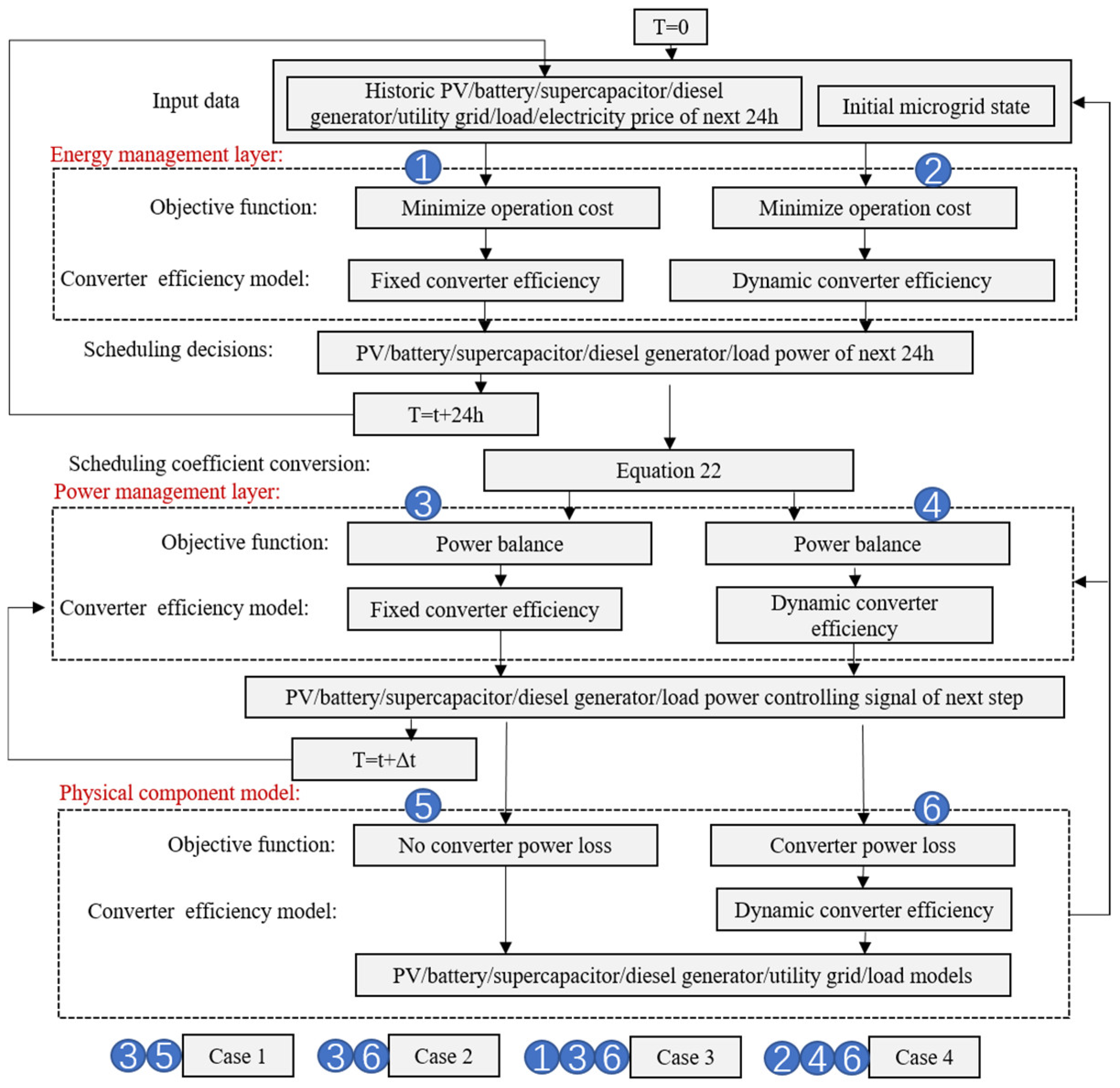
To study and demonstrate application of the microgrid supervisory system with consideration of the dynamic converter efficiency model to the DC microgrid, a simulation verification method was designed, as shown in the flow diagram in Figure 6. To determine the influence of the converter efficiency on the energy coordination of the microgrid, cases 1 and 2 were designed and compared. Case 1 was set to be a baseline for integration of the microgrid simulation with the idealized converter and the power management layer without consideration of converter efficiency, i.e., the converter efficiency is considered to be 100%. Case 2 is designed to be almost the same as case 1, with the difference that the converter in case 2 was not idealized.
To verify the performance of the proposed microgrid supervisory system when the dynamic converter efficiency is considered, we designed and compared cases 3 and 4. In case 3, the conventional converter efficiency model with multiple fixed converter efficiency values was implemented in the microgrid supervisory system. Case 4 represents integration of the microgrid simulation with the proposed microgrid supervisory system when the dynamic converter efficiency is considered.
As shown in Figure 6, ① and ② represent the energy management layer considering the fixed converter efficiency and considering the dynamic converter efficiency, respectively; ③ and ④ denote the power management layer that takes account of the fixed converter efficiency and the dynamic converter efficiency, respectively. ⑤ and ⑥, respectively, stand for whether the physical component model takes into account the dynamic converter efficiency. Thus, case 1 consists of ③ and ⑤; case 2 comprises ③ and ⑥; case 3 includes ①, ③ and ⑥; and case 4 contains ②, ④ and ⑥. The simulation starts when the time T is zero. The operating period of the energy management layer is 24 h. Equation (22) is applied to deal with the optimization results from the energy management layer. The power management layer then operates at time step Δ t to send the control signals for the PV, the BS, the UG, the SC, the DG, and the load demand.

4.2. Simulation Results and Analyses

4.2.1. Simulation Results for Case 1 and Case 2

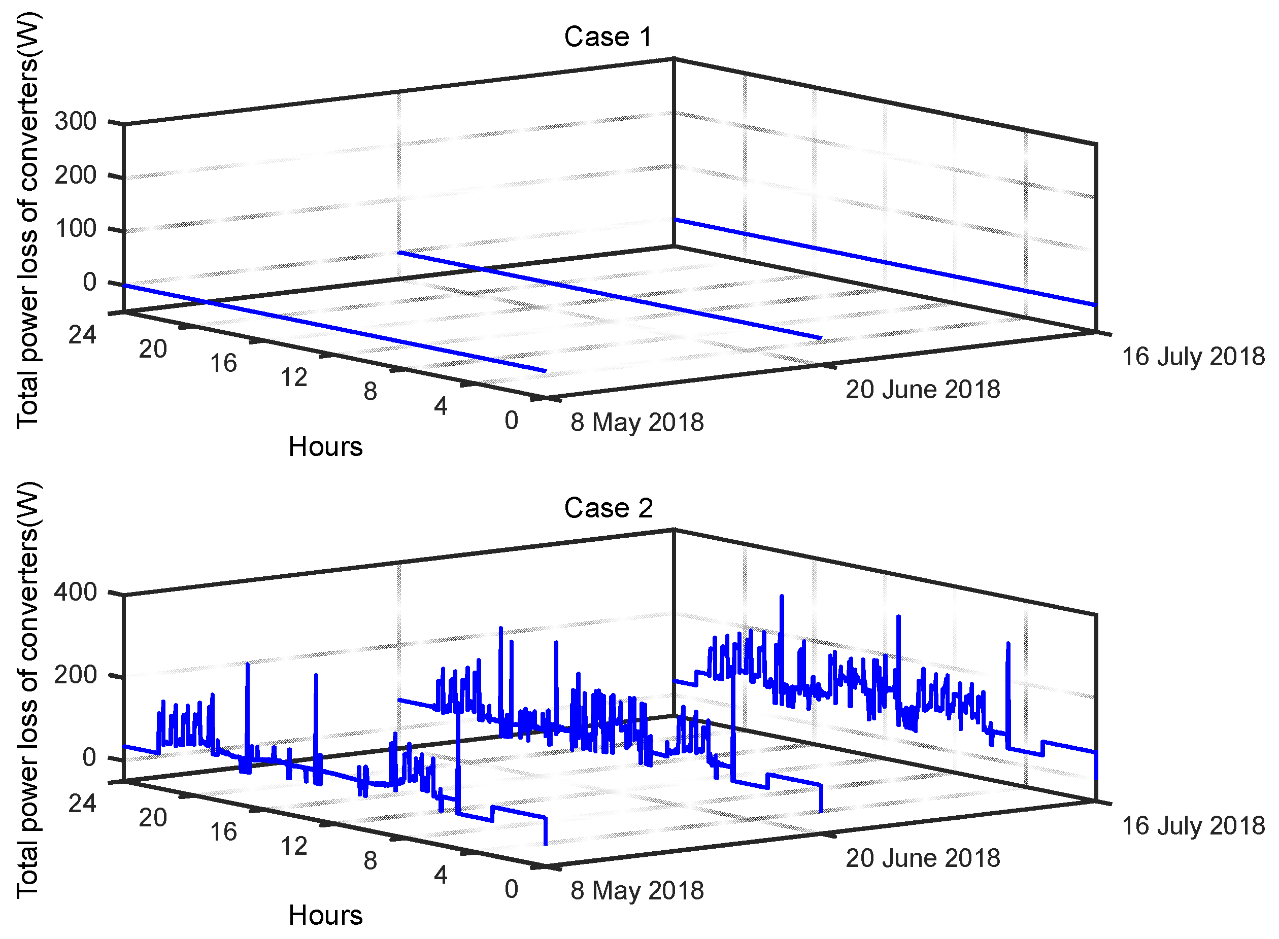
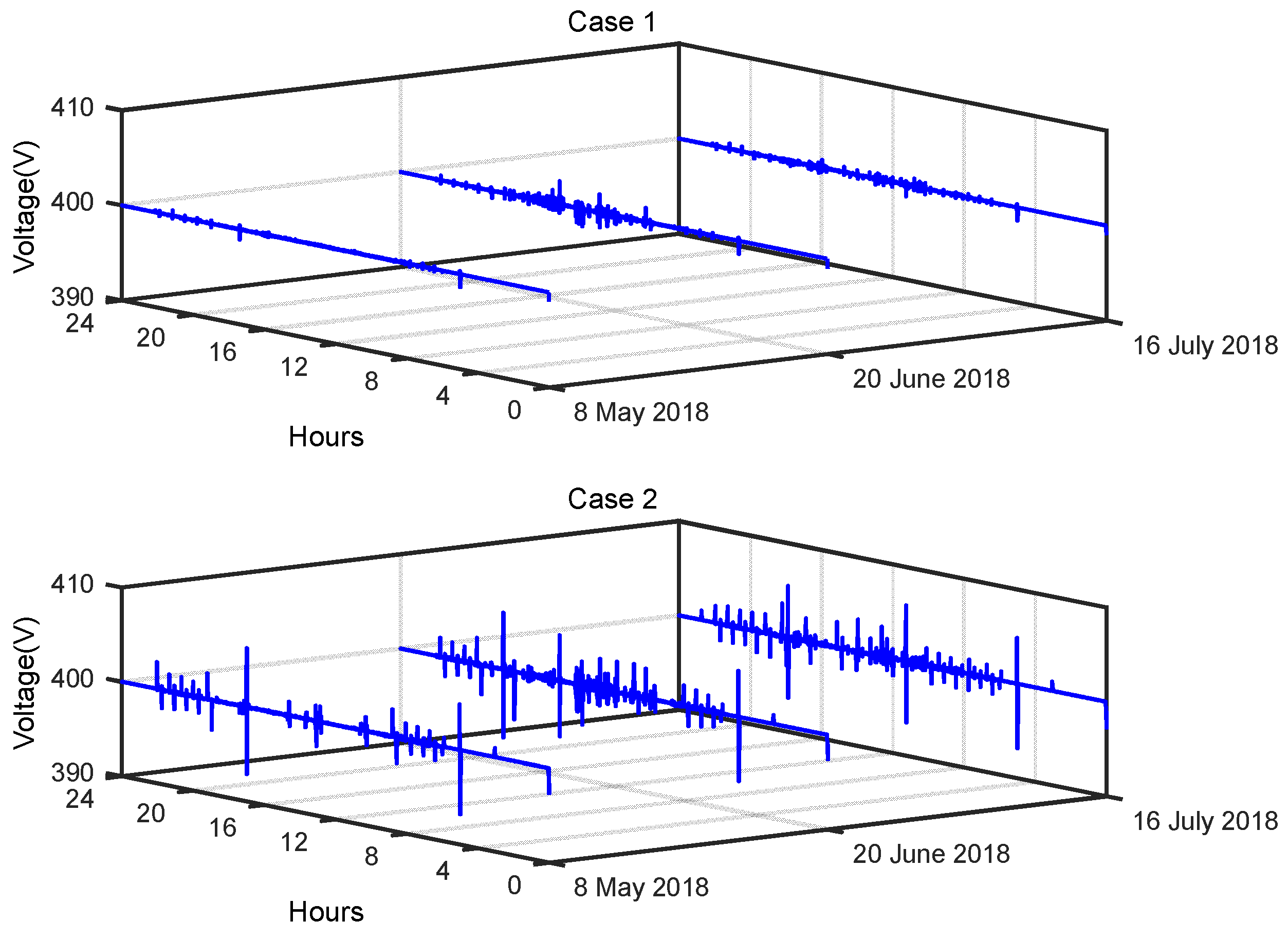
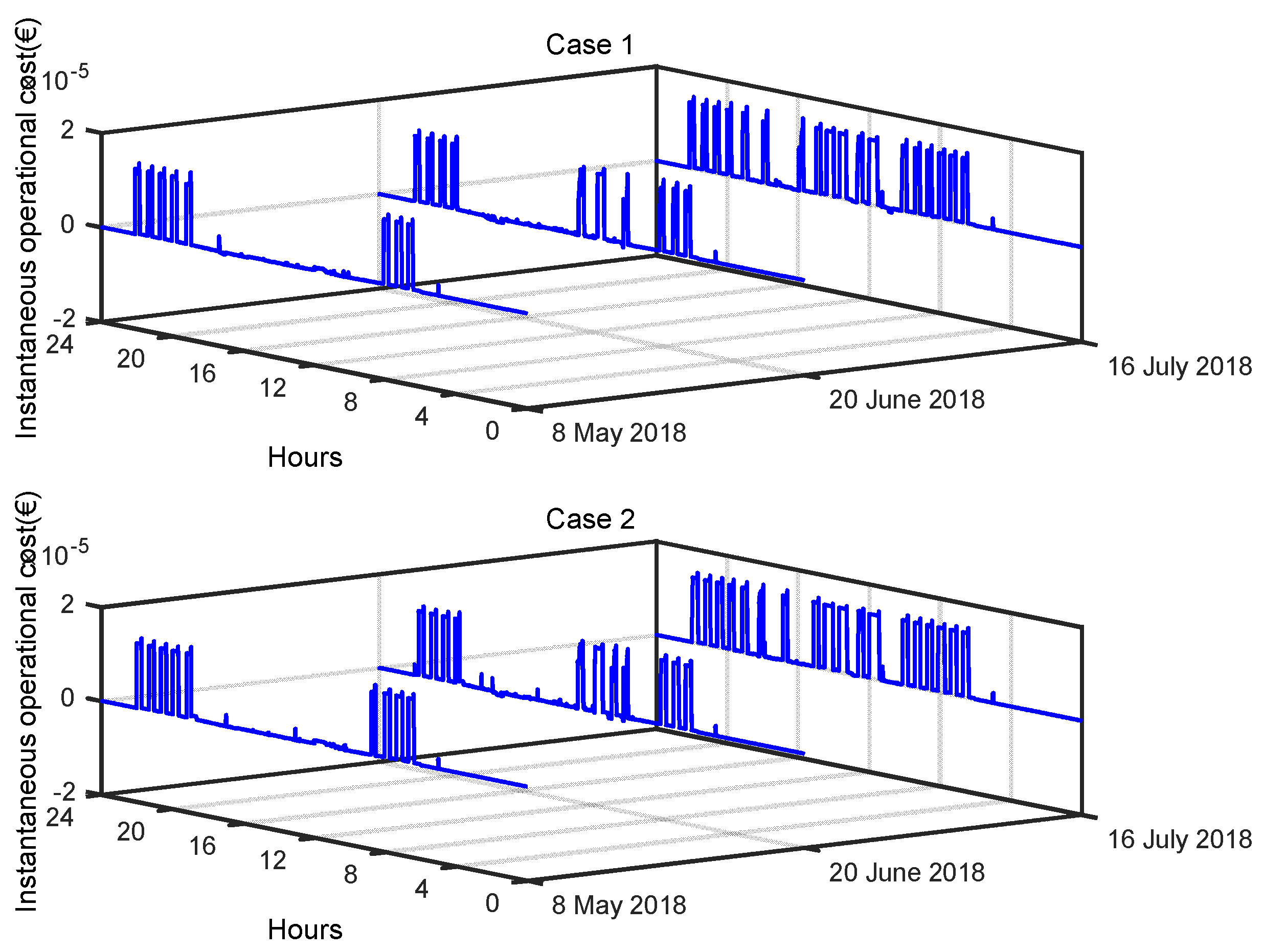
Cases 1 and 2 were applied in the simulation to provide comprehensive comparisons of the operational feasibility, converter power loss, DC bus fluctuations, and operating costs of the two cases. The detailed operating status of the commercial building microgrid over the three typical days is shown in Figure 7, Figure 8 and Figure 9.
The total converter power loss curves for case 1 and case 2 are shown in Figure 7. This figure indicates that the total converter power loss in case 1 is zero, while that of case 2 varies with the power distribution over the three typical days. On the sunny day of 8 May, the converter power loss was significantly smaller when compared with that on the other two typical days, which reflects the fact that flat PV generation on a sunny day can reduce the variation in the power transmitted by the converter, thus levelling out the power losses of the converter.
In Figure 8, the DC bus voltage curves for case 1 and case 2 are shown. This figure shows that the microgrid of a commercial building can operate well under different weather conditions while also maintaining a stable DC bus voltage. Comparison of the simulation results for cases 1 and 2 shows that the fluctuation of the DC bus in case 2 is greater than that in case 1, which indicates that the converter efficiency causes the fluctuations in the DC bus to be more significant. Additionally, the simulation results for the different weather conditions show that microgrid operation on the sunny day makes it easier to obtain lower fluctuations in the DC bus.
Figure 9 presents the instantaneous operating costs for case 1 and case 2. The instantaneous operating costs are higher around dawn and during the peak hours of electricity consumption at night; this occurs because, during these two periods, the PV generated power is low, the UG power limit is low, and the BS cannot provide sufficient power to meet the load demand for a long time, which leads to the higher cost of turning on the DG to meet the load demand. Furthermore, the results show that the instantaneous operating costs are higher in case 2 when compared with case 1, thus indicating that the converter’s power loss leads to higher operating costs. In addition, the operating cost of the microgrid in sunny weather is lower than that under the other two typical weather conditions. This illustrates that the smaller fluctuations that occur on sunny days can reduce the system’s operating costs.
A numerical comparison of the simulation results for case 1 and case 2 is presented in Table 2, based on three quantitative metrics which are used to evaluate the influence of the converter efficiency on the energy and power coordination of the microgrid. These metrics are (1) the total converter energy loss, ECV_SUM, (2) the root mean square error (RMSE), σVbus, which is commonly used to quantify the difference between an expected signal and the real signal and is used in this paper to indicate the power supply quality of the DC microgrid, and (3) the total operating cost, CTOTAL.
In the scenario on 8 May 2018, as shown in Table 2, ECV_SUM in case 2 is greater than the corresponding value in case 1, which proves that the converters in case 2 operate with a converter power loss. Subsequently, σVbus in case 2 is observed to be worse than the corresponding value in case 1, indicating that the converter’s power loss leads to a poorer power supply quality. Additionally, case 2 is more costly in terms of its operating economics, which is evidenced by the fact that the converter’s power losses result in higher operating costs. The simulation results for the scenarios on 20 June 2018 and 16 July 2018 lead to the same conclusions.

4.2.2. Simulation Results for Case 3 and Case 4

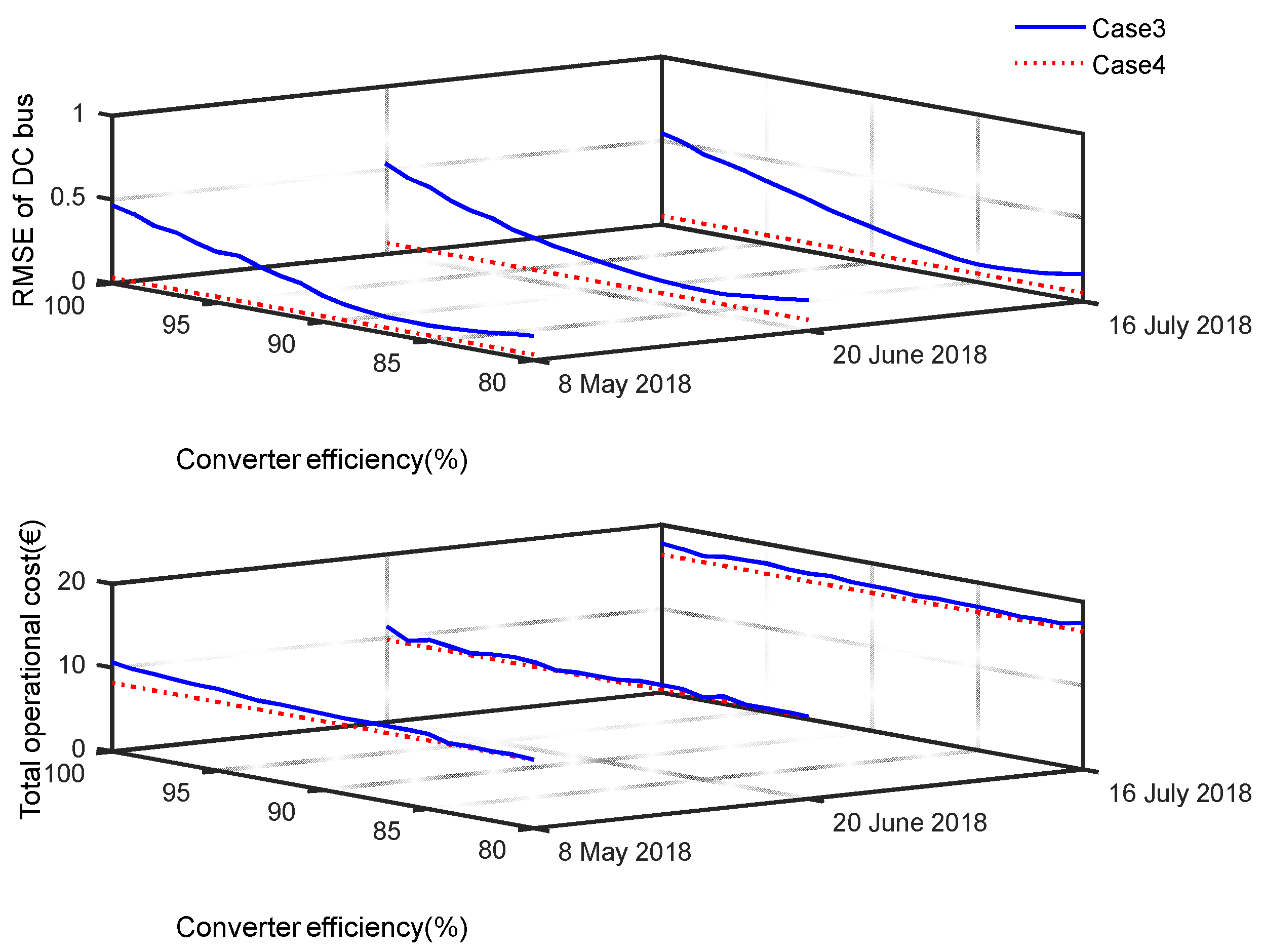
Cases 3 and 4 were applied in the simulation to provide a comprehensive comparison of the DC bus fluctuations and the total operating costs, wherein the converters in case 3 are idealized for a fixed conversion efficiency ranging from 80 to 100%, and the converters in case 4 are modelled as having the proposed dynamic conversion efficiency. The detailed operating states of the commercial building microgrids on the three typical days in cases 3 and 4 are shown in Figure 10.
In Figure 10, the blue lines represent the results for case 3 and the dotted red lines represent the results for case 4 on each day. In case 3, the RMSE of the DC bus evolves as a result of use of the fixed conversion efficiency, and the RMSE is approximately a quadratic function of the fixed converter efficiency, with the lowest RMSE appearing at approximately 85%. The RMSE in case 4 is consistently lower than that in case 3 on all three days. Furthermore, the total operating costs in case 3 and case 4 showed results that were almost the same as those obtained for the RMSE. At the same time, the results show that the total operating cost on the rainy day is much higher than that on the days with the other two types of weather, and the total operating cost for the sunny day in case 4 is the lowest.
A numerical comparison of the simulation results for case 3 and case 4 is presented in Table 3, using two quantitative metrics comprising the average RMSE of the DC bus and the average total operating cost. The average RMSE values for the DC bus in case 4 are lower than the corresponding values in case 3, while the average total operating costs in case 4 are lower than those in case 4. Therefore, the results for the two metrics in case 4 are better than those observed in case 3, indicating that the performance of the proposed supervisory system with a dynamic converter efficiency model is better than the corresponding system with a conventional fixed converter efficiency model.
The results above demonstrate that all four cases ensure normal operation of the commercial building microgrid. Additionally, the converter’s power loss results in higher operating costs and fluctuations in the DC bus. Furthermore, case 2, case 3, and case 4 represent the three methods that can be used to resolve the drawbacks in power management caused by converter power losses. The proposed case 3 with the dynamic converter efficiency model performs well in both reducing the operating costs and increasing the power quality of the DC bus.

5. Conclusions

To minimize the operating costs for a commercial building microgrid, this paper proposes a supervision system that considers the constraints of the physical components, the uncertainties of the PV sources and the loads, and the dynamic converter efficiency; the proposed supervision system is applied to a scaled-down commercial building microgrid. This supervision system consists of two layers: an energy management layer that optimizes scheduling of the sources and loads by considering long-term optimization, and a power management layer that reschedules the power flow for power balancing in real time and also deals with the results of the problems of PV source power uncertainty and load prediction. To reflect the power losses of the converters accurately, a dynamic efficiency model of the converters was established, which provides an important basis for energy and power loss replenishment of the commercial building microgrid. The supervision system was verified in MATLAB/Simulink simulations under a dataset including three typical weather conditions: cloud, sunshine, and rain. The comparison of simulation results for cases 1 and 2 illustrates the impact of converter efficiency on energy coordination in microgrids. The simulation results of cases 3 and 4 verify that the performance in terms of power supply quality and operating costs of the proposed microgrid supervisory system considering a dynamic converter efficiency is superior to that of the microgrid supervisory system considering a fixed converter efficiency.
Multi-microgrids can increase the penetration rates for renewable energy, reduce the power system’s interactions with the high-level power grid, alleviate the impact of the system on the high-level power grid, and reduce the requirement for operation of DG units in the power system. Because the research in this paper provides a good foundation for microgrid power and energy management, a multi-microgrid energy management system can be developed in future research work.

Author Contributions

Conceptualization, W.B. and D.W.; Methodology, W.B. and D.W.; Software, W.B. and J.Y.; Validation, W.B. and J.Y.; Formal analysis, D.W. and X.S.; Investigation, X.S.; Resources, D.W. and Z.M.; Data curation, Z.M.; Writing—original draft, W.B., D.W. and Z.M.; Writing—review & editing, W.B., D.W., Z.M. and Y.P.; Visualization, J.X.; Supervision, D.W.; Project administration, W.B.; Funding acquisition, W.B. All authors have read and agreed to the published version of the manuscript.

Funding

This work was supported by the Research Foundation for Youth Scholars of Beijing Technology and Business University under Grant QNJJ2022-40.

Institutional Review Board Statement

Not applicable.

Informed Consent Statement

Not applicable.

Data Availability Statement

Not applicable.

Conflicts of Interest

The authors declare no conflict of interest.

References

  1. Birol, D.F. World Energy Outlook; International Energy Agency: Paris, France, 2022. [Google Scholar]
  2. Kaewnern, H.; Wangkumharn, S.; Deeyaonarn, W.; Yousaf, A.U.; Kongbuamai, N. Investigating the Role of Research Development and Renewable Energy on Human Development: An Insight from the Top Ten Human Development Index Countries. Energy 2023, 262, 125540. [Google Scholar] [CrossRef]
  3. Kim, G.; Hur, J. A Probabilistic Approach to Potential Estimation of Renewable Energy Resources Based on Augmented Spatial Interpolation. Energy 2023, 263, 125582. [Google Scholar] [CrossRef]
  4. Hille, E.; Oelker, T.J. International Expansion of Renewable Energy Capacities: The Role of Innovation and Choice of Policy Instruments. Ecol. Econ. 2023, 204, 107658. [Google Scholar] [CrossRef]
  5. Yang, Z.; Yang, F.; Min, H.; Tian, H.; Hu, W.; Liu, J.; Eghbalian, N. Energy Management Programming to Reduce Distribution Network Operating Costs in the Presence of Electric Vehicles and Renewable Energy Sources. Energy 2023, 263, 125695. [Google Scholar] [CrossRef]
  6. Yan, R.; Wang, J.; Huo, S.; Qin, Y.; Zhang, J.; Tang, S.; Wang, Y.; Liu, Y.; Zhou, L. Flexibility Improvement and Stochastic Multi-Scenario Hybrid Optimization for an Integrated Energy System with High-Proportion Renewable Energy. Energy 2023, 263, 125779. [Google Scholar] [CrossRef]
  7. Demirci, A.; Öztürk, Z.; Tercan, S.M. Decision-Making between Hybrid Renewable Energy Configurations and Grid Extension in Rural Areas for Different Climate Zones. Energy 2023, 262, 125402. [Google Scholar] [CrossRef]
  8. Kushwaha, P.K.; Ray, P.; Bhattacharjee, C. Optimal Sizing of a Hybrid Renewable Energy System: A Socio-Techno-Economic-Environmental Perspective. J. Sol. Energy Eng. 2023, 145, 031003. [Google Scholar] [CrossRef]
  9. Amir, M.; Prajapati, A.K.; Refaat, S.S. Dynamic Performance Evaluation of Grid-Connected Hybrid Renewable Energy-Based Power Generation for Stability and Power Quality Enhancement in Smart Grid. Front. Energy Res. 2022, 10, 861282. [Google Scholar] [CrossRef]
  10. Ghelani, D. Literature Review on Coordinated Control of Interconnected Microgrid and Energy Storage System; Authorea: New York, NY, USA, 2022; Preprints. [Google Scholar] [CrossRef]
  11. Bai, W.; Wang, D.; Sun, X.; Yu, J.; Xu, J.; Pan, Y. An Online Multi-Level Energy Management System for Commercial Building Microgrids with Multiple Generation and Storage Systems. IEEE Open Access J. Power Energy 2023, 10, 195–207. [Google Scholar] [CrossRef]
  12. Bai, W.; Sechilariu, M.; Locment, F. DC Microgrid System Modeling and Simulation Based on a Specific Algorithm for Grid-Connected and Islanded Modes with Real-Time Demand-Side Management Optimization. Appl. Sci. 2020, 10, 2544. [Google Scholar] [CrossRef] [Green Version]
  13. Bai, W.; Sechilariu, M.; Locment, F. On-Grid/off-Grid DC Microgrid Optimization and Demand Response Management. In Proceedings of the 2020 22nd European Conference on Power Electronics and Applications (EPE’20 ECCE Europe), Lyon, France, 7–11 September 2020; pp. 1–10. [Google Scholar]
  14. Mojumder, M.R.H.; Hasanuzzaman, M.; Cuce, E. Prospects and Challenges of Renewable Energy-Based Microgrid System in Bangladesh: A Comprehensive Review. Clean Techn. Environ. Policy 2022, 24, 1987–2009. [Google Scholar] [CrossRef]
  15. Ceglia, F.; Macaluso, A.; Marrasso, E.; Roselli, C.; Vanoli, L. Energy, Environmental, and Economic Analyses of Geothermal Polygeneration System Using Dynamic Simulations. Energies 2020, 13, 4603. [Google Scholar] [CrossRef]
  16. Rao, S.N.V.B.; Pavan Kumar, Y.V.; Amir, M.; Ahmad, F. An Adaptive Neuro-Fuzzy Control Strategy for Improved Power Quality in Multi-Microgrid Clusters. IEEE Access 2022, 10, 128007–128021. [Google Scholar] [CrossRef]
  17. Singh, K.; Amir, M.; Ahmad, F.; Refaat, S.S. Enhancement of Frequency Control for Stand-Alone Multi-Microgrids. IEEE Access 2021, 9, 79128–79142. [Google Scholar] [CrossRef]
  18. Alipour, M.; Mohammadi-Ivatloo, B.; Zare, K. Stochastic Scheduling of Renewable and CHP-Based Microgrids. IEEE Trans. Ind. Inf. 2015, 11, 1049–1058. [Google Scholar] [CrossRef]
  19. Zheng, W.; Zhu, J.; Luo, Q. Distributed Dispatch of Integrated Electricity-Heat Systems with Variable Mass Flow. IEEE Trans. Smart Grid 2022, 1. [Google Scholar] [CrossRef]
  20. Norouzi, F.; Hoppe, T.; Elizondo, L.R.; Bauer, P. A Review of Socio-Technical Barriers to Smart Microgrid Development. Renew. Sustain. Energy Rev. 2022, 167, 112674. [Google Scholar] [CrossRef]
  21. Thirunavukkarasu, G.S.; Seyedmahmoudian, M.; Jamei, E.; Horan, B.; Mekhilef, S.; Stojcevski, A. Role of Optimization Techniques in Microgrid Energy Management Systems—A Review. Energy Strategy Rev. 2022, 43, 100899. [Google Scholar] [CrossRef]
  22. Huang, Z.; Guo, Z.; Ma, P.; Wang, M.; Long, Y.; Zhang, M. Economic-Environmental Scheduling of Microgrid Considering V2G-Enabled Electric Vehicles Integration. Sustain. Energy Grids Netw. 2022, 32, 100872. [Google Scholar] [CrossRef]
  23. Domenech, B.; Ferrer-Martí, L.; García, F.; Hidalgo, G.; Pastor, R.; Ponsich, A. Optimizing PV Microgrid Isolated Electrification Projects—A Case Study in Ecuador. Mathematics 2022, 10, 1226. [Google Scholar] [CrossRef]
  24. Kumar, A.; He, X.; Deng, Y.; Singh, A.R.; Sah, B.; Kumar, P.; Bansal, R.C.; Bettayeb, M.; Rayudu, R. A Sustainable Rural Electrification Based on a Socio-Techno-Economic-Environmental-Political Microgrid Design Framework. Energy Environ. Sci. 2022, 15, 4213–4246. [Google Scholar] [CrossRef]
  25. Yin, M.; Li, K.; Yu, J. A Data-Driven Approach for Microgrid Distributed Generation Planning under Uncertainties. Appl. Energy 2022, 309, 118429. [Google Scholar] [CrossRef]
  26. Chen, X.; Dong, W.; Yang, Q. Robust Optimal Capacity Planning of Grid-Connected Microgrid Considering Energy Management under Multi-Dimensional Uncertainties. Appl. Energy 2022, 323, 119642. [Google Scholar] [CrossRef]
  27. Cheng, Z.; Jia, D.; Li, Z.; Si, J.; Xu, S. Multi-Time Scale Dynamic Robust Optimal Scheduling of CCHP Microgrid Based on Rolling Optimization. Int. J. Electr. Power Energy Syst. 2022, 139, 107957. [Google Scholar] [CrossRef]
  28. Ali Dashtaki, A.; Mehdi Hakimi, S.; Hasankhani, A.; Derakhshani, G.; Abdi, B. Optimal Management Algorithm of Microgrid Connected to the Distribution Network Considering Renewable Energy System Uncertainties. Int. J. Electr. Power Energy Syst. 2023, 145, 108633. [Google Scholar] [CrossRef]
  29. Zia, M.F.; Nasir, M.; Elbouchikhi, E.; Benbouzid, M.; Vasquez, J.C.; Guerrero, J.M. Energy Management System for a Hybrid PV-Wind-Tidal-Battery-Based Islanded DC Microgrid: Modeling and Experimental Validation. Renew. Sustain. Energy Rev. 2022, 159, 112093. [Google Scholar] [CrossRef]
  30. Ferahtia, S.; Djeroui, A.; Rezk, H.; Houari, A.; Zeghlache, S.; Machmoum, M. Optimal Control and Implementation of Energy Management Strategy for a DC Microgrid. Energy 2022, 238, 121777. [Google Scholar] [CrossRef]
  31. Merabet, A.; Al-Durra, A.; El-Saadany, E.F. Energy Management System for Optimal Cost and Storage Utilization of Renewable Hybrid Energy Microgrid. Energy Convers. Manag. 2022, 252, 115116. [Google Scholar] [CrossRef]
  32. Chen, T.; Cao, Y.; Qing, X.; Zhang, J.; Sun, Y.; Amaratunga, G.A.J. Multi-Energy Microgrid Robust Energy Management with a Novel Decision-Making Strategy. Energy 2022, 239, 121840. [Google Scholar] [CrossRef]
  33. Erol, Ö.; Başaran Filik, Ü. A Stackelberg Game Approach for Energy Sharing Management of a Microgrid Providing Flexibility to Entities. Appl. Energy 2022, 316, 118944. [Google Scholar] [CrossRef]
  34. Alabdullah, M.H.; Abido, M.A. Microgrid Energy Management Using Deep Q-Network Reinforcement Learning. Alex. Eng. J. 2022, 61, 9069–9078. [Google Scholar] [CrossRef]
  35. Kavitha, V.; Malathi, V.; Guerrero, J.M.; Bazmohammadi, N. Energy Management System Using Mimosa Pudica Optimization Technique for Microgrid Applications. Energy 2022, 244, 122605. [Google Scholar] [CrossRef]
  36. Ullah, Z.; Wang, S.; Wu, G.; Xiao, M.; Lai, J.; Elkadeem, M.R. Advanced Energy Management Strategy for Microgrid Using Real-Time Monitoring Interface. J. Energy Storage 2022, 52, 104814. [Google Scholar] [CrossRef]
  37. Guo, S.; Li, P.; Ma, K.; Yang, B.; Yang, J. Robust Energy Management for Industrial Microgrid Considering Charging and Discharging Pressure of Electric Vehicles. Appl. Energy 2022, 325, 119846. [Google Scholar] [CrossRef]
  38. Den Broeck, G.V.; Martinez, W.; Dalla Vecchia, M.; Ravyts, S.; Driesen, J. Conversion Efficiency of the Buck Three-Level DC–DC Converter in Unbalanced Bipolar DC Microgrids. IEEE Trans. Power Electron. 2020, 35, 9306–9319. [Google Scholar] [CrossRef]
  39. Rajasekaran, R.; Usha Rani, P. Combined HCS–RBFNN for Energy Management of Multiple Interconnected Microgrids via Bidirectional DC–DC Converters. Appl. Soft Comput. 2021, 99, 106901. [Google Scholar] [CrossRef]
  40. Rai, S.K.; Mathur, H.D.; Hasan, S. Converter Efficiency Improvement of Islanded DC Microgrid with Converter Array. In Modelling, Simulation and Intelligent Computing; Goel, N., Hasan, S., Kalaichelvi, V., Eds.; Lecture Notes in Electrical Engineering; Springer: Singapore, 2020; Volume 659, pp. 64–73. ISBN 9789811547744. [Google Scholar]
  41. Tang, Y.; Hu, W.; Zhang, B.; Cao, D.; Hou, N.; Li, Y.; Chen, Z.; Blaabjerg, F. Deep Reinforcement Learning-Aided Efficiency Optimized Dual Active Bridge Converter for the Distributed Generation System. IEEE Trans. Energy Convers. 2022, 37, 1251–1262. [Google Scholar] [CrossRef]
  42. Ahmed, M.; Meegahapola, L.; Vahidnia, A.; Datta, M. Stability and Control Aspects of Microgrid Architectures–A Comprehensive Review. IEEE Access 2020, 8, 144730–144766. [Google Scholar] [CrossRef]
  43. Wu, X.; Cao, W.; Wang, D.; Ding, M. A Multi-Objective Optimization Dispatch Method for Microgrid Energy Management Considering the Power Loss of Converters. Energies 2019, 12, 2160. [Google Scholar] [CrossRef] [Green Version]
  44. Bozorgi, A.M.; Gholami-Khesht, H.; Farasat, M.; Mehraeen, S.; Monfared, M. Model Predictive Direct Power Control of Three-Phase Grid-Connected Converters With Fuzzy-Based Duty Cycle Modulation. IEEE Trans. Ind. Appl. 2018, 54, 4875–4885. [Google Scholar] [CrossRef]
  45. Aghdam, M.M.; Li, L.; Zhu, J. Comprehensive Study of Finite Control Set Model Predictive Control Algorithms for Power Converter Control in Microgrids. IET Smart Grid 2020, 3, 1–10. [Google Scholar] [CrossRef]
  46. Hossain, M.Z.; Rahim, N.A.; Selvaraj, J.a. Recent Progress and Development on Power DC-DC Converter Topology, Control, Design and Applications: A Review. Renew. Sustain. Energy Rev. 2018, 81, 205–230. [Google Scholar] [CrossRef]
  47. Fan, Z.; Fan, B.; Peng, J.; Liu, W. Operation Loss Minimization Targeted Distributed Optimal Control of DC Microgrids. IEEE Syst. J. 2021, 15, 5186–5196. [Google Scholar] [CrossRef]
  48. Pachanapan, P. Dynamic Modelling and Simulation of Power Electronic Converter in DIgSILENT Simulation Language (DSL): Islanding Operation of Microgrid System with Multi-Energy Sources. In Modelling and Simulation of Power Electronic Converter Dominated Power Systems in PowerFactory; Gonzalez-Longatt, F.M., Rueda Torres, J.L., Eds.; Power Systems; Springer International Publishing: Cham, Switzerland, 2021; pp. 67–93. ISBN 978-3-030-54123-1. [Google Scholar]
  49. Kong, L.; Nian, H. Transient Modeling Method for Faulty DC Microgrid Considering Control Effect of DC/AC and DC/DC Converters. IEEE Access 2020, 8, 150759–150772. [Google Scholar] [CrossRef]
  50. Wei, B.; Han, X.; Wang, P.; Yu, H.; Li, W.; Guo, L. Temporally Coordinated Energy Management for AC/DC Hybrid Microgrid Considering Dynamic Conversion Efficiency of Bidirectional AC/DC Converter. IEEE Access 2020, 8, 70878–70889. [Google Scholar] [CrossRef]
  51. Wen, Q.; Liu, G.; Wu, W.; Liao, S. Genetic Algorithm-Based Operation Strategy Optimization and Multi-Criteria Evaluation of Distributed Energy System for Commercial Buildings. Energy Convers. Manag. 2020, 226, 113529. [Google Scholar] [CrossRef]
  52. Thirugnanam, K.; El Moursi, M.S.; Khadkikar, V.; Zeineldin, H.H.; Hosani, M.A. Energy Management Strategy of a Reconfigurable Grid-Tied Hybrid AC/DC Microgrid for Commercial Building Applications. IEEE Trans. Smart Grid 2022, 13, 1720–1738. [Google Scholar] [CrossRef]
  53. Yin, C.; Wu, H.; Locment, F.; Sechilariu, M. Energy Management of DC Microgrid Based on Photovoltaic Combined with Diesel Generator and Supercapacitor. Energy Convers. Manag. 2017, 132, 14–27. [Google Scholar] [CrossRef]
  54. Han, L.; Liang, L.; Kang, Y.; Qiu, Y. A Review of SiC IGBT: Models, Fabrications, Characteristics, and Applications. IEEE Trans. Power Electron. 2021, 36, 2080–2093. [Google Scholar] [CrossRef]
  55. Xuan, Y.; Yang, X.; Chen, W.; Liu, T.; Hao, X. A Novel Three-Level CLLC Resonant DC-DC Converter for Bidirectional EV Charger in DC Microgrids. IEEE Trans. Ind. Electron. 2021, 68, 2334–2344. [Google Scholar] [CrossRef]
  56. Wu, H.; Sechilariu, M.; Locment, F. Influence of Dynamic Efficiency in the DC Microgrid Power Balance. Energies 2017, 10, 1563. [Google Scholar] [CrossRef] [Green Version]
  57. IBM. CPLEX; IBM: Armonk, NY, USA, 2023. [Google Scholar]
  58. Yin, C.; Wu, H.; Sechilariu, M.; Locment, F. Power Management Strategy for an Autonomous DC Microgrid. Appl. Sci. 2018, 8, 2202. [Google Scholar] [CrossRef] [Green Version]
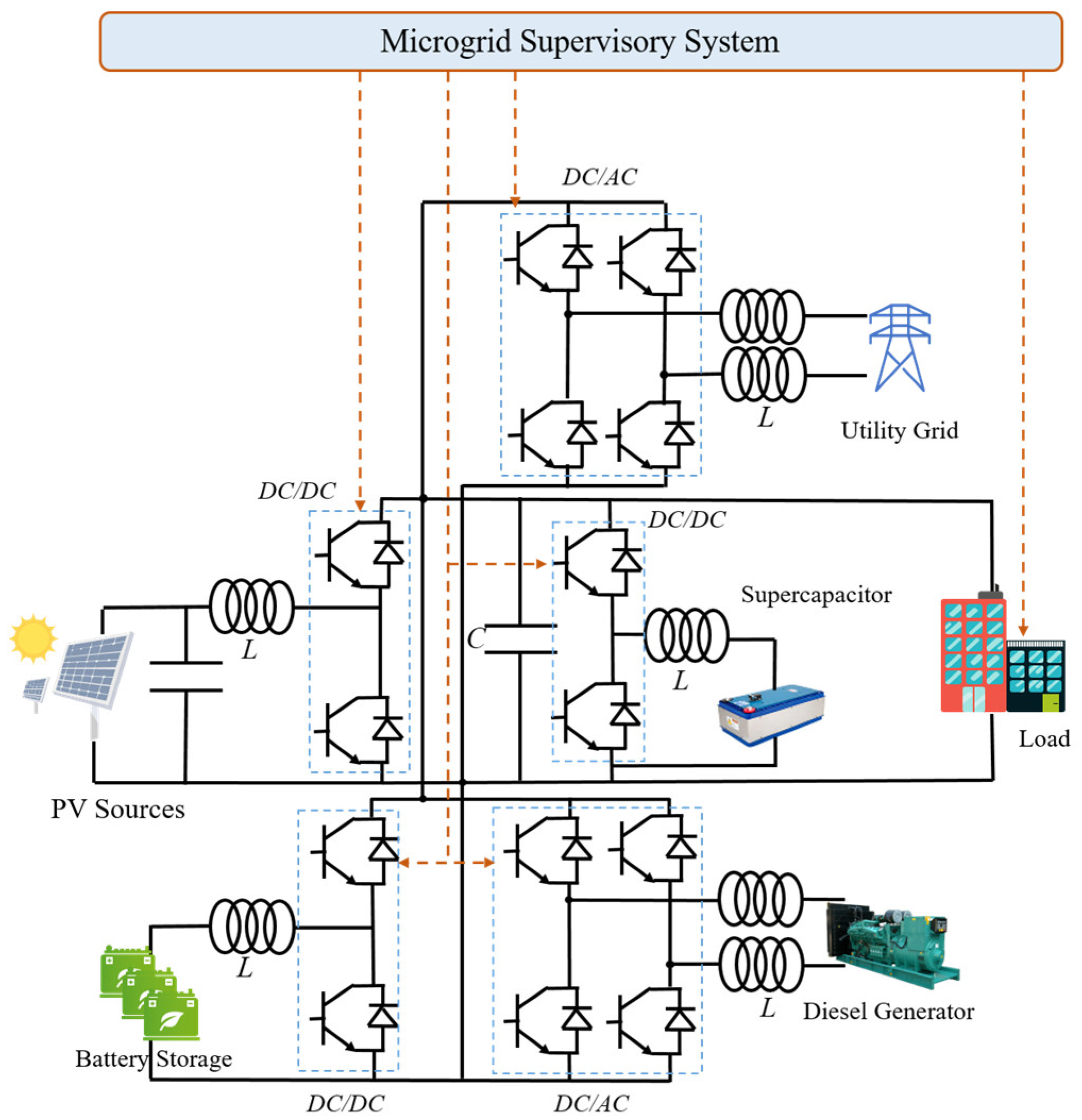
Figure 1. Commercial building microgrid structure.
Sustainability 15 06413 g001
Figure 2. Example of a PV boost converter.
Sustainability 15 06413 g002
Figure 3. Microgrid supervisory system design.
Sustainability 15 06413 g003
Figure 4. Real weather dataset.
Sustainability 15 06413 g004
Figure 5. Profiles of the PV power, the scaled building load demand, and their predicted characteristics.
Sustainability 15 06413 g005
Figure 6. Flow diagram representing the simulation and demonstration of the microgrid supervisory system.
Sustainability 15 06413 g006
Figure 7. Total converter power loss curves for case 1 and case 2.
Sustainability 15 06413 g007
Figure 8. DC bus curves for case 1 and case 2.
Sustainability 15 06413 g008
Figure 9. Instantaneous operating costs for case 1 and case 2.
Sustainability 15 06413 g009
Figure 10. RMSE characteristics for the DC bus and the total operating costs in case 3 and case 4.
Sustainability 15 06413 g010
Table 1. Simulation parameters.
Title 1ParameterValueUnitParameterValueUnit
PV P P V _ M P P T 1.75kW a P V 0.013-
p u P V _ P N 5EUR/kWh b P V 21.376-
Load k L _ C R 80% or 100%- p u L _ P N _ N R 10EUR/kWh
BS S O C B S _ M A X 80%- a B S _ b u c 0.074-
S O C B S _ M I N 20%- b B S _ b u c 16.611-
S O C B S _ 0 50%- a B S _ b s t 0.083-
C R E F 33Ah b B S _ b s t 19.859-
c B S _ A g i n g 0.07EUR/kWh p B S _ C H M A X / p B S _ D C H M A X 1kW
UG p U G _ I M A X / p U G _ S M A X 200 or 600W a U G _ i n v 0.006-
a U G _ r e c 0.011- b U G _ i n v 46.991-
b U G _ r e c 28.429- c U G _ S ( t ) / c U G _ I ( t ) 0.01 or 0.7 or 0.1EUR/kWh
DG p D G _ O N M A X 1.5kW a D G _ r e c 0.005-
c D G _ F u e l 1.2EUR/kWh b D G _ r e c 30.181-
c D G _ A g i n g 0.63EUR/kWh -
SC S O C S C M A X 45%- p S C _ C H M A X / p S C _ D C H M A X 1.5kW
S O C S C M I N 75%- a S C _ b u c 0.141-
S O C S C _ 0 75%- b S C _ b u c −15.010-
C S C 94F a S C _ b s t 0.148-
v S C _ R a t e d 75V b S C _ b s t −11.260-
c S C _ A g i n g 0.3EUR/kWh
DC bus v D C * 400V
Table 2. Simulation results for case 1 and case 2.
ConditionECV_SUM (kWh)σVbusCTOTAL (EUR)
On 8 May 2018Case 100.016.91
Case 21.730.138.82
On 20 June 2018Case 100.048.53
Case 21.960.1810.38
On 16 July 2018Case 100.0316.34
Case 22.130.1718.90
Table 3. Simulation results for case 3 and case 4.
ConditionAverage σVbusAverage CTOTAL (EUR)
On 8 May 2018Case 30.099.20
Case 40.038.18
On 20 June 2018Case 30.2510.22
Case 40.079.79
On 16 July 2018Case 30.2617.30
Case 40.0516.45
Disclaimer/Publisher’s Note: The statements, opinions and data contained in all publications are solely those of the individual author(s) and contributor(s) and not of MDPI and/or the editor(s). MDPI and/or the editor(s) disclaim responsibility for any injury to people or property resulting from any ideas, methods, instructions or products referred to in the content.