Article

Fuzzy-Based Fifteen-Level VSC for STATCOM Operations with Single DC-Link Voltage

by
Lakshminarayana Gadupudi
1,
Gudapati Sambasiva Rao
2,
Rachakonda Venkata Lakshmi Narayana Divakar
3,
Hasmat Malik
4,5,*,
Faisal Alsaif
6,
Sager Alsulamy
7 and
Taha Selim Ustun
8,*
1
Department of EEE, VNR Vignana Jyothi Institute of Engineering and Technology, Hyderabad 500090, Telangana, India
2
Department of EEE, R.V.R. & J.C. College of Engineering, Guntur 522019, Andhra Pradesh, India
3
Department of EEE, ANITS, Visakhapatnam 531162, Andhra Pradesh, India
4
Department of Electrical Power Engineering, Faculty of Electrical Engineering, University Technology Malaysia (UTM), Johor Bahru 81310, Malaysia
5
Department of Electrical Engineering, Graphic Era Deemed to be University, Dehradun 248002, Uttarakhand, India
6
Department of Electrical Engineering, College of Engineering, King Saud University, Riyadh 11421, Saudi Arabia
7
Energy & Climate Change Division, Sustainable Energy Research Group, Faculty of Engineering & Physical Sciences, University of Southampton, Southampton SO16 7QF, UK
8
Fukushima Renewable Energy Institute, AIST (FREA), National Institute of Advanced Industrial Science and Technology (AIST), Koriyama 9630298, Fukushima, Japan
*
Authors to whom correspondence should be addressed.
Sustainability 2023, 15(7), 6188; https://doi.org/10.3390/su15076188
Submission received: 30 January 2023 / Revised: 27 March 2023 / Accepted: 30 March 2023 / Published: 4 April 2023
(This article belongs to the Special Issue Power Electronics and Renewable Energy Technologies)

Abstract

:
A static synchronous compensator (STATCOM) is a powerful mechanism for balancing reactive power and uplift voltage stability in a transmission system. Nowadays, the desire to save energy by reducing losses is prioritized as an essential target instead of increasing the power generation for the sustainability of any nation’s growth plans. As a result, power-electronics-based converters are more significant for power savings in transmission systems. STATCOM based on voltage source converters (VSC) are operated to improve on stable performance conditions as well as to minimize the harmonic distortions in a power system. Hence, this paper explores low harmonic distortions of fifteen-level VSC structured STACOM using only one DC-link voltage to balance the reactive power and to manage the voltage profile in large power transmission systems. STATCOM consisting of H-bridge type VSCs and binary weighted transformers was utilized to maintain an AC system voltage at 132 kV, 50 Hz. The three stages of VSCs were operated with meticulous firing angles based on converter levels for controlling THD (total harmonic distortion) and providing system improvement. The proposed model of the fifteen-level H-bridge type voltage source converters with fuzzy logic decoupled control algorithm based STATCOM can be used for large power range applications with a small number of switches. This model attained stable operation of the system with a low harmonic deviation at any dynamical conditions. The simulation results using MATLAB showed that the system’s operation was enhanced, with a smoother response and improved steady state performance.

1. Introduction

FACTS (flexible alternating current transmission system) devices are utilized to improve controllability and to lead power transmission towards sustainable operation in the system [1,2]. They can be operated easily with lagging and leading modes of states at any reactive power control point for the system steady state conditions [3]. The power system voltage profile is maintained because of the reactive power balancing by using appropriate power electronic converters in dynamical conditions [4]. Hence, STATCOM is a suitable FACTS device for the enhancement of the system’s voltage profile and for the management of the system’s reactive power. STATCOM is connected in shunt with transmission lines to deliver or extract reactive power to control the voltage in transmission lines, and thus losses in the system can be avoided. A multilevel H-bridge voltage source converter (VSC) maintains the constant voltage profile with the reactive power variation at the transmission system [5]. Reactive power in transmission lines is balanced by binary-weighted-transformer-based seven-level VSC through STATCOM applications, and voltage dips are minimized with specific firing angle equations [6]. A phase-shifted PWM technique with cascade converters is used to mitigate voltage sags in power grid operations [7].
STATCOMs operate to keep the balanced system voltage with less harmonic content and provide voltage shaping at various unbalanced conditions [8]. The perfect power balance for grid operations is adopted by the separation of positive and negative sequence voltages through decoupled algorithms [9]. Nine-level VSC-based STATCOM implements a stable voltage reference point during dynamic load situations with single DC link capacitance [10]. The performance indicator of multi-modular converters has been studied for sizing and economical deviations [11]. One cycle control five-level converter is established for improvement of the power quality in terms of balancing the voltage flickering [12]. High-power STATCOM with combined energy storage (ES-STATCOM) is very popular and utilizes modular multi-level converters [13]. Fundamental switching of PWM-based 24-pulse converters generates constant voltage through the control of reactive power changes in transmission systems [14]. In high-voltage applications, VSCs can be combined in different topologies to enhance the speed and effect of the power management response [15]. Hybrid multilevel converter-based STATCOM operations have been implemented for the elimination of voltage dips during load variations in the system [16]. The cascade submodule of half bridge structures was designed for inverter operation in high voltage and high-power applications [17]. Seven-level binary weighted transformer connected VSC-based STATCOM was made for huge power transmission systems in order to control the reactive power changes [18]. A single DC link voltage is utilized to balance the power losses and switching losses in the distributed static synchronous compensator [19].
A dynamic response analysis of STATCOM and SVC operations to achieve stable boundary limits for voltage and frequency in a power system has been discussed in [20]. A precise level of VSC is injected into the reactive current at various stages of sequences in order to maintain the system voltage with balanced capacitor voltages [21]. The phase angle regulator is used to control the stability and security issues of power grid operations, which has been used in renewable power sources entablement [22]. The mathematical model approach of nonlinear systems is presented for the cost reduction of power system operations and to minimize power losses by reactive power balances through STATCOM at various load profiles [23]. The thermal stress on DC link capacitors is controlled to eliminate the switching losses in multilevel converters so as to establish the effective operations [24]. This paper describes various novel methodologies in VSC-based STATCOM operations and what is experienced at different application loads [25].
In this paper, the proposed fifteen-level voltage source H-bridge converters and fuzzy-logic-decoupled-control-algorithm-based STATCOM sustainable model is established for large power range applications with the smallest number of switches. The contribution of this work to the current body of knowledge is that the developed model attains stable operation of the system with a low harmonic deviation at different operational dynamic modes.

2. STATCOM Formation and Working Principle

2.1. Working Principle

STATCOM consists of weighted transformers, and various levels of VSC have been imported to generate AC voltage with less of a harmonic spectrum. VSCs consist of few H-bridges and solo DC-link capacitance along with binary weighted transformers, which has the turn sequence of 1:2:4: …:2n−1. STATCOM’s AC output voltage is always controlled by the DC-link capacitance based on the phase angle deviations between the grid’s voltage and the STATCOM’s AC output voltage during dynamic operations. STATCOM can absorb reactive power from the system if its output voltage is less than the grid’s voltage. Meanwhile, STATCOM delivers reactive power towards the grid if its output voltage is higher than the grid’s voltage. Unlike traditional multi-level VSCs, the biggest advantage of using sustainable multi-level VSC with a single DC-link capacitor and binary-weighted transformers is having voltage waveforms with multiple steps.

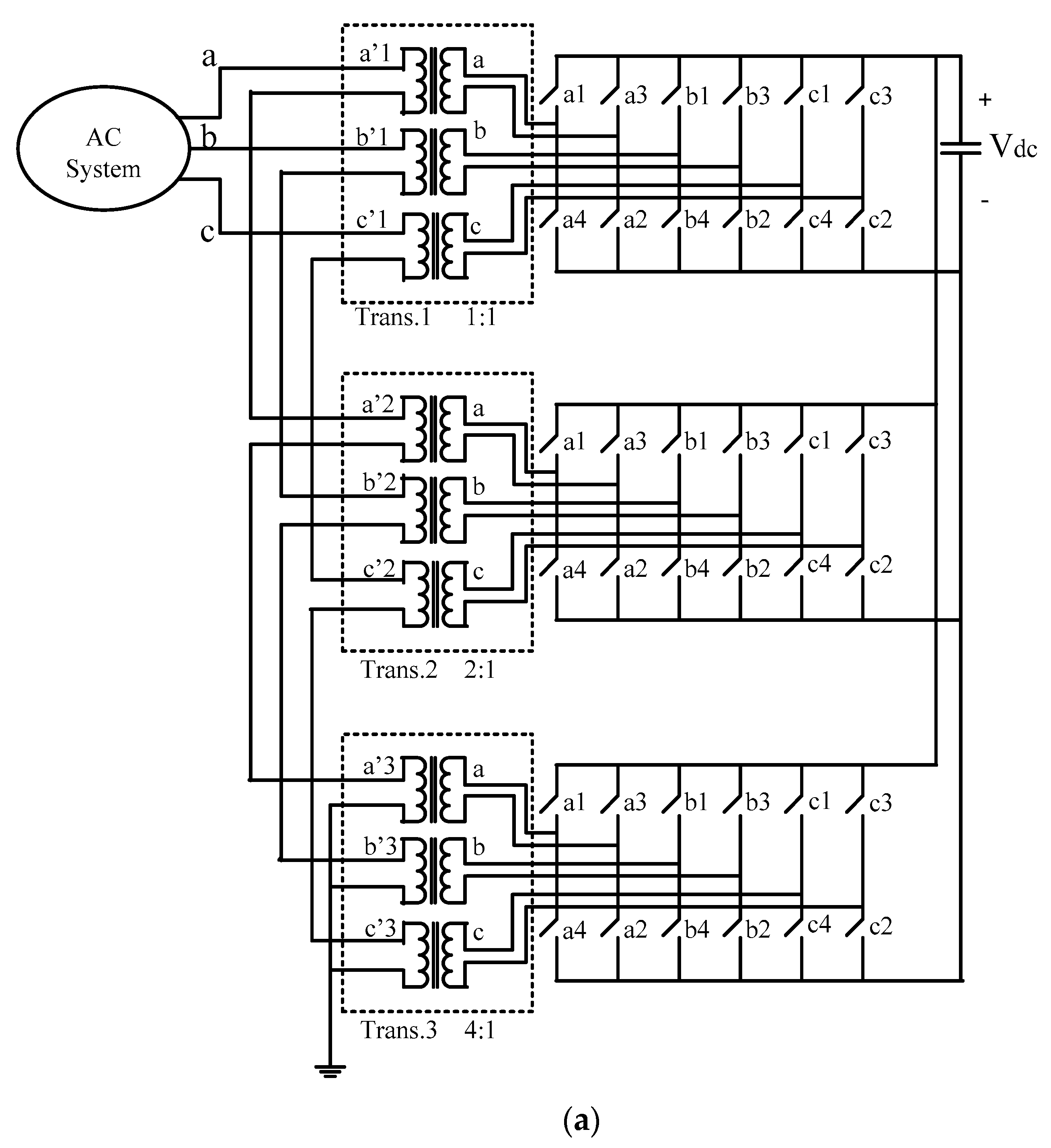
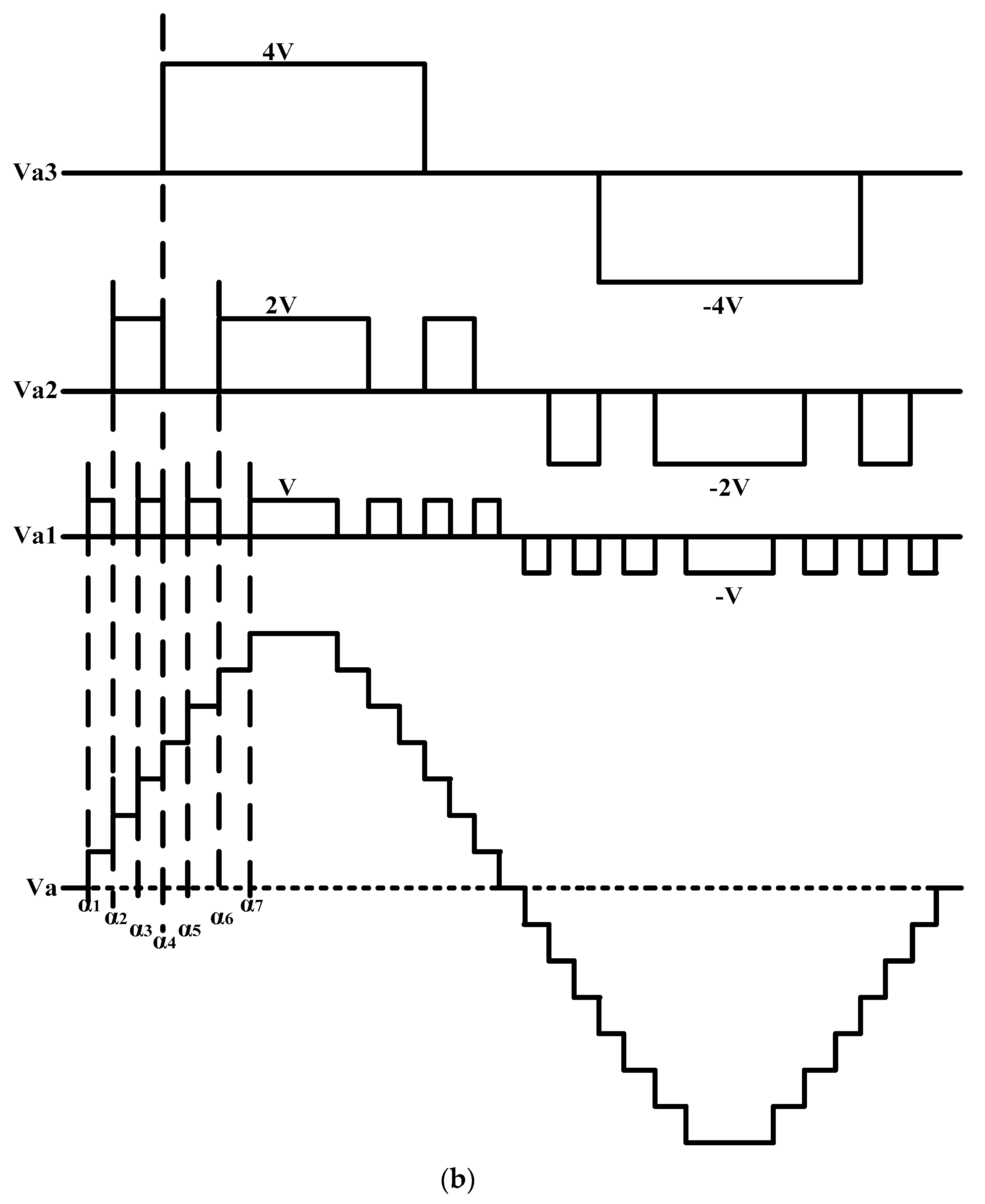
2.2. A Proposed Fifteen-Level VSC-Based STATCOM Formation

A fifteen-level VSC-based STATCOM with a unique DC-link voltage configuration with binary weighted transformers and power electronic commutating switches such as IGBTs or GTOs is proposed. Figure 1a shows a binary weighted transformer connected fifteen-level VSC-based STATCOM design model.
The configuration has a DC-link capacitance and three VSC bridges, and every VSC consists of three H-bridges. VSC output voltages are connected to transformers with 1:2:4 turn ratios and each level moves through the switching angle of H-bridges in VSC formation. Figure 1b shows the 1:2:4 turn ratios of the one, two, and three transformer output voltage levels waveform sequence.
The firing angles of the switches as per [6,10], ‘α1’, ‘α2’, ‘α3’, ‘α4’, ‘α5’, ‘α6’, and ‘α7’, are calculated in Equation (1).
α i = sin 1 i 0.5 7 , i = 1 , 2 , 3 , 4 , 5 , 6 , 7 . W h e r e   i = l e v e l   o f   V S C α 1 = 4.1 ° , α 2 = 12.37 ° , α 3 = 20.92 ° , α 4 = 30 ° , α 5 = 40 ° , α 6 = 51.79 °   a n d   α 7 = 68.21 °
Figure 1c shows the fifteen-level VSC output voltage waveform and its harmonic spectra. The THD of the fifteen-level VSC’s output voltage is 5.50% and is better than the conventional VSC arrangement.

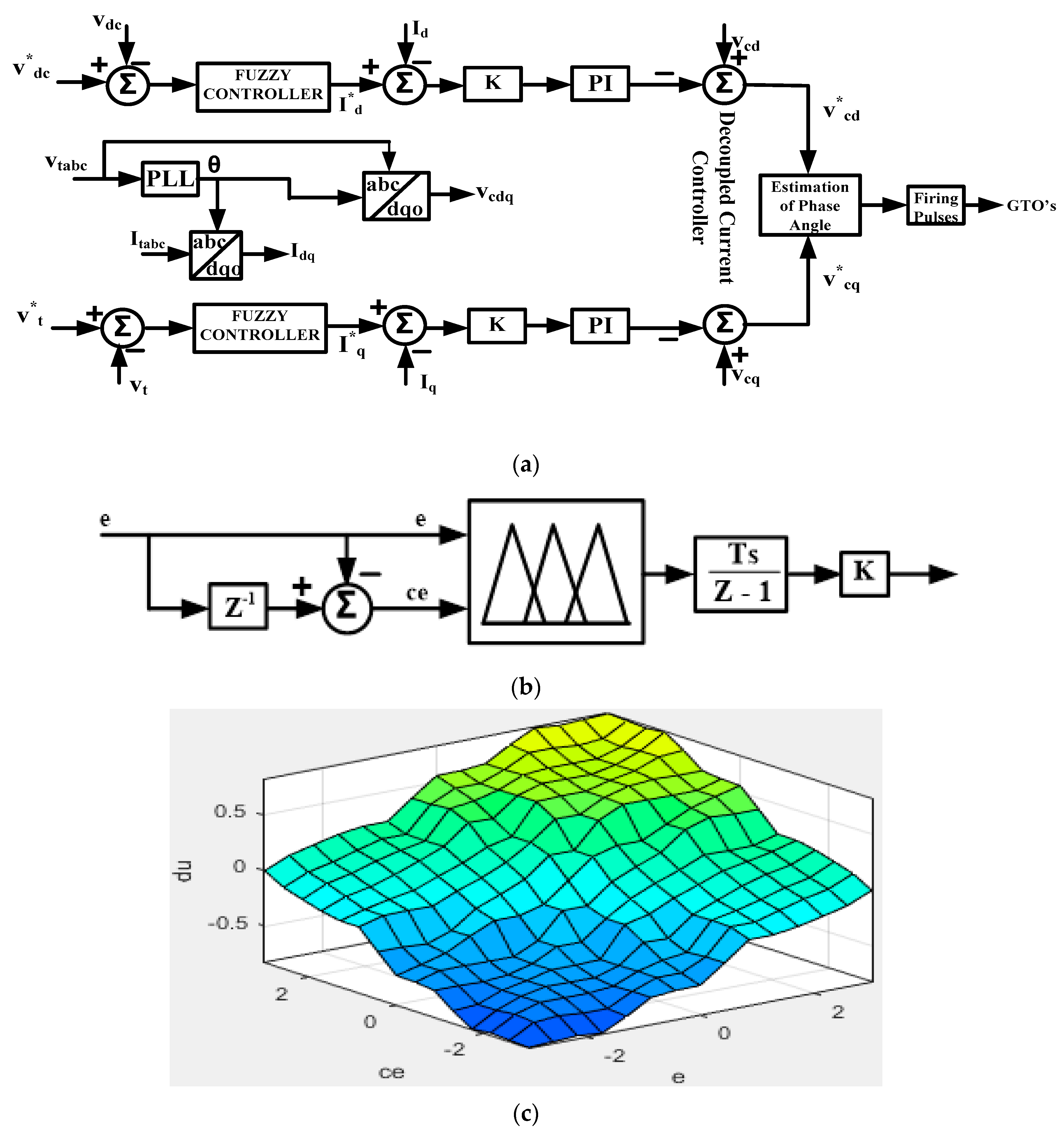
3. Fuzzy Control Methodology

The proposed fuzzy logic control method illustrates sustainable transmission system terminal voltage, current, and power, as shown in Figure 2a.

3.1. Phase Locked Loop

The synchronization signals (cos θ and sin θ), i.e., phase locked loop (PLL), are used to generate the system voltage (θ) phase angles, as shown in Figure 2a. This is the control’s reference phase angle and is generated based on the terminal voltage zero crossing point. These phase angles are employed through abc-dq0 transformations of voltage and current. A system terminal voltage  V t a b c  is converted into  V d  and  V q  based on the system’s frequency. Reference phase angles are calculated with a PI controller according to dq frame error signals  V q V q .

3.2. Fuzzy Rule DC Voltage Controller

The rule-based fuzzy logic [26,27] controller is depicted in Figure 2b. Three stages of controller are established for the process of fuzzifications, rule membership operations, and defuzzification. Fuzzification is an operation of converting crisp values into fuzzy values. Rule membership functions are applied to crisp inputs to establish their degree of suitable fuzzy sets. The rule membership operations are invoked by the rules for suitable fuzzy sets and generate results. These fuzzy membership results are transferred to crisp values called defuzzification. The centroid approach is the sort of defuzzification method used. The triangle membership function is the most widely used membership function. The linguistic values of rule membership operations are indicated in Table 1, such as negative big (NB), negative medium (NM), negative small (NS), zero (ZE), positive small (PS), positive medium (PM), and positive big (PB). Here,  e  stands for error and  c e  stands for change in error. Figure 2c depicts the control surface  d u = f ( e , c e ) . The reference d-axis current  I d  is calculated by the DC voltage controller via the fuzzy converter.
A fuzzy logic controller is supplied by an error  e d c = e d c r e f e d c  and change in error  c e d c n = e d c n e d c n 1  at  n th samplings.

3.3. Fuzzy Rule AC Voltage Controller

A reference q-axis current  I q  is calculated by the AC voltage controller. The reactive component current  I q  varyies depending on the reactive power variation in the transmission system. The current  I q  is rising, i.e., reactive power flows increase towards the AC system through STATCOM, while the AC system’s voltage rises towards the reference point. Furthermore, the current  I q  decreases, i.e., reactive power flows decrease towards the AC system through STATCOM, while the AC system’s voltage decreases towards the reference point. The procedure is repeated until the AC system’s voltage meets the point set by the fuzzy logic converter. The control surface  d u = f ( e , c e )  is shown in Figure 2c. A fuzzy logic controller supplies the error  e t = e t r e f e t  and the change in error  c e t = e t n e t n 1  at  n t h  samplings.

3.4. Decoupled Current Controller

The AC system’s voltage, AC converter output voltage, and STATCOM current are expressed as
V t a V t b V t c V c a V c b V c c = R + L d d t I s t a I s t b I s t c
Applying Park’s transformation to the above equations results in
R + L d d t w L w L R + L d d t I d I q = V t d V c d V t q V c q
V t d  and  V t q  refer to the  d  and  q  axis’s component of the AC terminal voltages.  V c d  and  V c q  refer to the  d  and  q  axis’s component of the AC converter output voltages. The d-axis and q-axis components of the STATCOM currents are referred to as  I d  and  I q , respectively. The  d  and  q  axis’s reference AC converter output voltages are calculated as,
V c d V c q = V t d V t q R w L w L R I d I q K 0 0 K I d I d I q I q
From Equations (3) and (4), we consider the reference converter voltage as equal to their sensed value,
R + L d d t w L w L R + L d d t I d I q = V t d V t q V c d V c q = V t d V t q V t d V t q + R w L w L R I d I q + K 0 0 K I d I d I q I q R + L d d t w L w L R + L d d t I d I q = R w L w L R I d I q + K 0 0 K I d I d I q I q R w L w L R I d I q + L d I d d t L d I q d t = R w L w L R I d I q + K 0 0 K I d I d I q I q L d I d d t L d I q d t = K ( I d I d ) K ( I q I q )
Taking z-transform in Equation (5) results in
I d z = z 1 T z + z 1 I d z
I q z = z 1 T z + z 1 I q z
T = L/K, K is selected on L/T, where L is the interface inductance and T is the settling time.

3.5. Assessment of Phase Angles

A constant DC-link voltage is retained for continuous active power, and  δ  is obtained in Equation (8).
δ = tan 1 v c q v c d

4. STATCOM Performance and Simulation Results

A sustainable fifteen-level VSC-based STATCOM using single DC-link voltage has been implemented for a 132 kV, 50 Hz AC system. STATCOM’s dynamic performance is estimated by changing the reactive power at the reference point for various load conditions. In addition, the system checks the terminal voltage variations at the reference point for stable operation and sustainability improvement with minimum harmonic distortion.

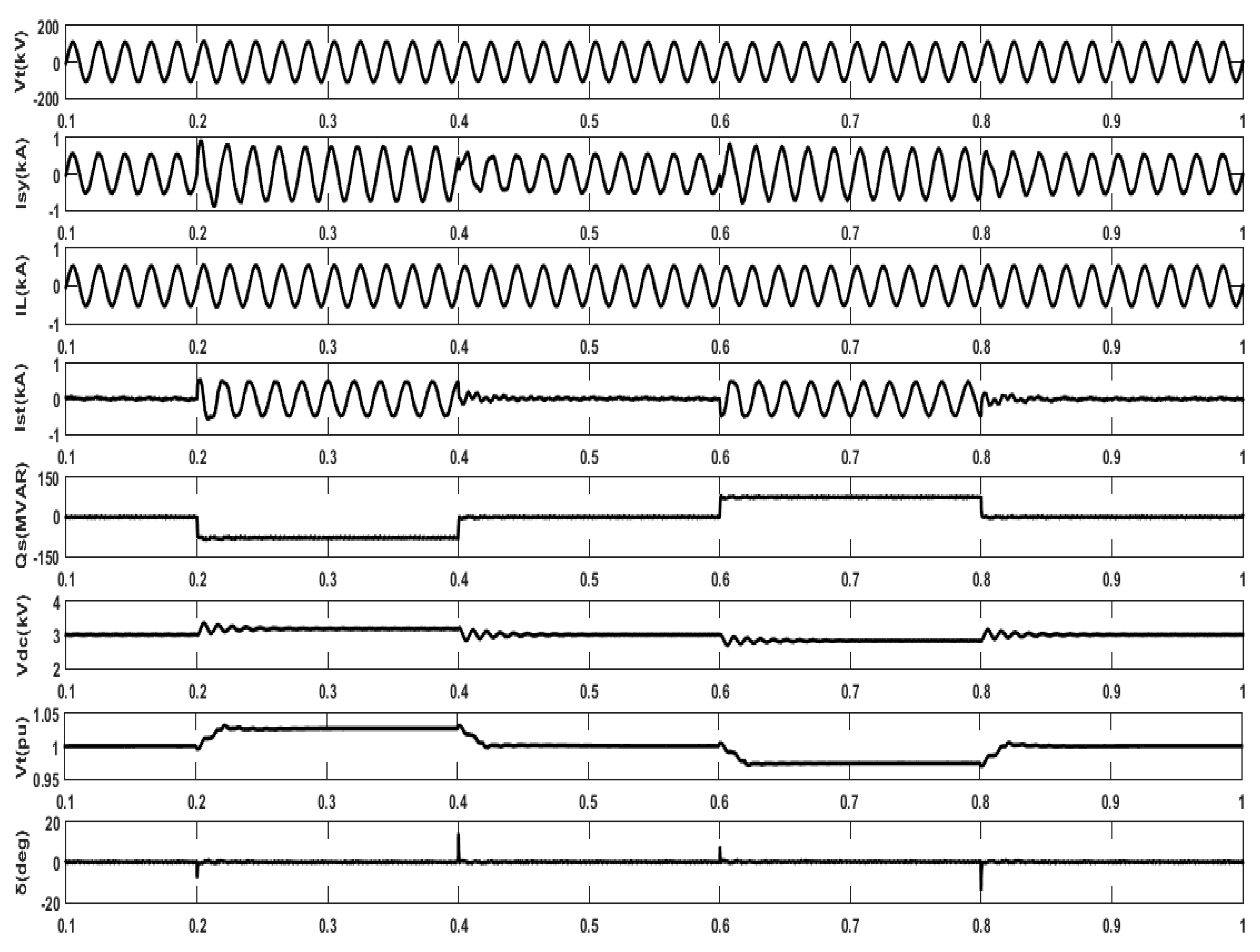
4.1. Performance When Changing Reactive Power under Continuous Load

Figure 3a shows the dynamic performance of binary weighted transformer integrated fifteen-level VSC constructed STATCOM by changing the reference reactive power under continuous loads. The reactive power changed from 0 to 100 MVAR at time intervals of 0.2 s to 0.4 s, demonstrating an inductive operation. During this period, reactive power flows towards STATCOM at an AC system point, then the converter AC output voltage decreases, i.e., the converter’s AC output voltage is less than the system’s terminal voltage. Thus, reactive power changes to 0 between 0.4 s and 0.6 s, and the STATCOM sustainability dynamic performance is investigated. At this period, the converter’s AC output voltage is same as the system’s terminal voltage, so reactive power changes are not required. Next, the reactive power is changed from 0 to −100 MVAR during 0.6 s to 0.8 s, which demonstrates a capacitive operation. During this period, reactive power flows towards the AC system at the STATCOM point, then the converter’s AC output voltage increases, i.e., converter’s AC output voltage is larger than the system’s terminal voltage. Hence, reactive power is set to 0 at intervals between 0.8 s and 1.0 s, then floating operation of the transmission system i.e., reactive power changes, are not required again. STATCOM’s sustainability dynamic performance is examined. It is found that harmonic distortion is kept within sustainable limits and the system operation is enhanced.
Figure 3b shows the performance evaluation of fifteen-level VSC constructed STATCOM harmonics current spectra during inductive operation and capacitive operation at a continuous load. The THD of the STATCOM’s current is 2.07% during the inductive operations, i.e., the reference reactive power is 100 MVAR and 3.51% during the capacitive operations, i.e., the reference reactive power is −100 MVAR.

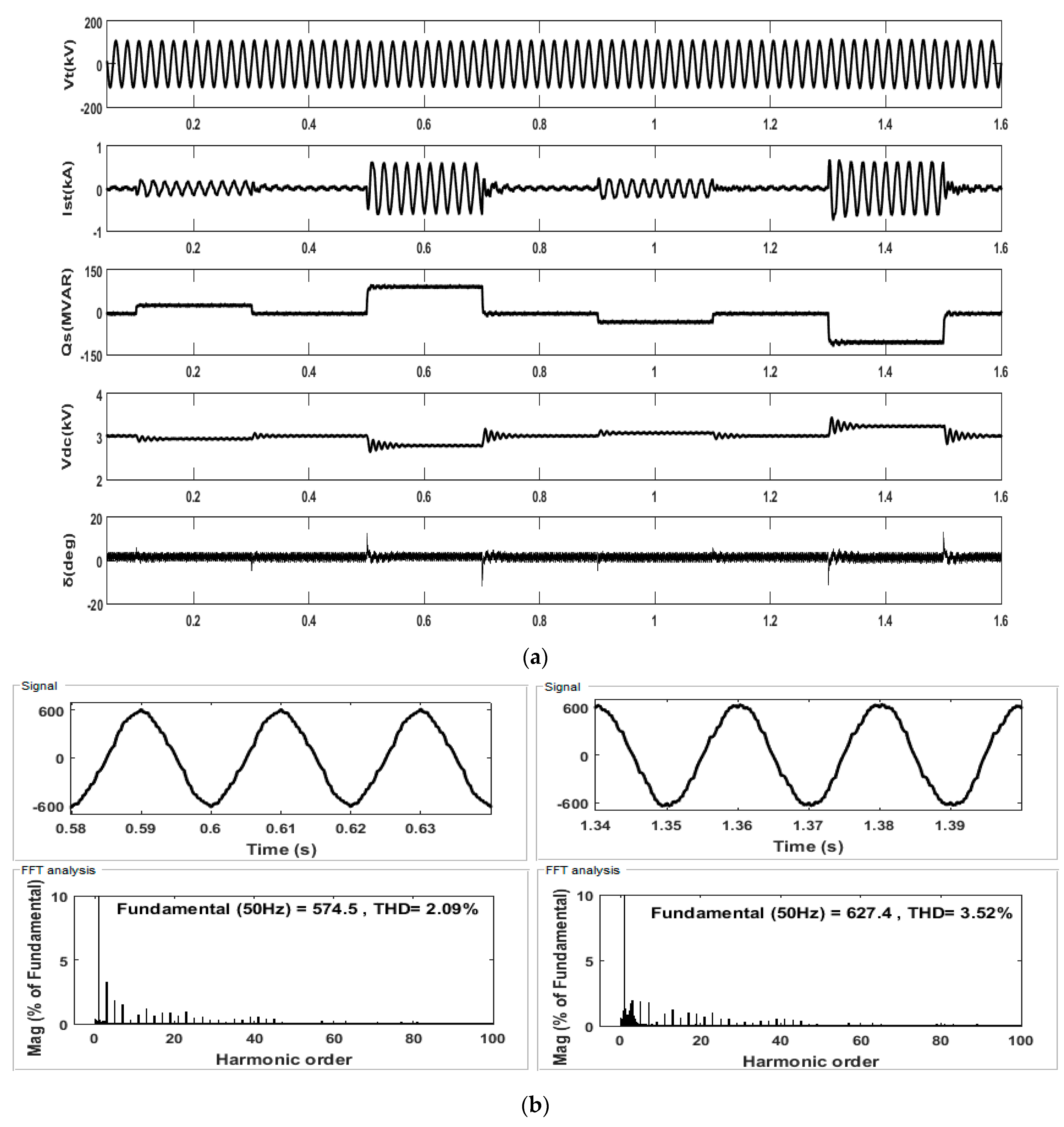
4.2. Performance When Changing Reactive Power under Cumulative Load

Figure 4a shows the dynamic performance of the binary weighted transformer integrated fifteen-level VSC constructed STATCOM by changing the reference reactive power under a cumulative load. Reactive power changes towards 40 MVAR from the initial point 0 at 0.1 s to 0.3 s, and subsequently 60 MVAR reactive power load is added in time intervals of 0.3 s and 0.5 s. Then, the total cumulative load is reached at 100 MVAR, demonstrating an inductive operation. During this time length from 0.1 s to 0.5 s, reactive power flows towards STATCOM at the AC system point, then the converter’s AC output voltage decreases, i.e., converter’s AC output voltages is lower than the system terminal voltage. Thus, reactive power is changed to 0 between 0.5 s and 0.7 s and the STATCOM sustainability dynamic performance is observed. At this point, the converter’s AC output voltages are same as the system’s terminal voltages; hence, reactive power changes are not required. Next, the reactive power is changed to −40 MVAR from initial point 0 from 0.7 s to 0.9 s, and subsequently −60 MVAR reactive power load is added in intervals of 0.9 s and 1.1 s. Then, the total cumulative load is −100 MVAR, demonstrating a capacitive operation. During the period from 0.7 s to 1.1 s, reactive power flows towards the AC system at the STATCOM point, then the converter’s AC output voltage increases, i.e., the converter’s AC output voltage is larger than the system’s terminal voltage. Hence, the reactive power is set to 0 in intervals of 1.1 s to 1.2 s, then floating operation of the transmission system, i.e., reactive power change, is not required again. STATCOM sustainability dynamic performance is inspected and shows system enhancement through acceptable harmonic distortion at cumulative loads.
Figure 4b shows the performance evaluation of fifteen-level VSC constructed STATCOM harmonics current spectra on inductive operation and capacitive operation at a cumulative load. THD of the STATCOM’s current is 2.09% during inductive operation, i.e., reference reactive power is 100 MVAR and 3.54% during capacitive operation, i.e., the reference reactive power is −100 MVAR.

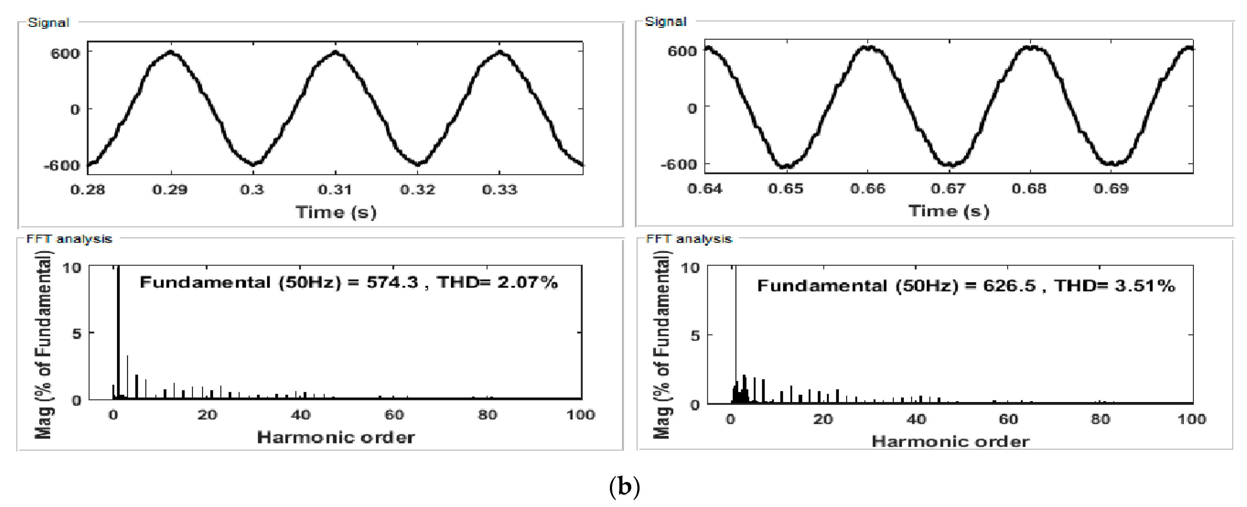
4.3. Performance When Changing Reactive Power under a Disintegration Load

Figure 5a shows the sustainable dynamic performance of binary weighted transformer integrated fifteen-level VSC constructed STATCOM by changing the reference reactive power under a disintegration load. The reactive power is changed from 0 to 30 MVAR at intervals of 0.1 s to 0.3 s, demonstrating an inductive operation. During this period, reactive power flows towards STATCOM at an AC system point, then the converter AC output voltage decreases, i.e., the converter AC output voltage is less than the system terminal voltage. Thus, the reactive power changes to 0 between 0.3 s and 0.5 s and the STATCOM sustainability dynamic performance is observed. At this period, the converter AC output voltage is the same as the system terminal voltage, hence reactive power change is not required. Next, the disintegration reactive power is changed to 100 MVAR from the initial time of 0 in time intervals 0.5 s to 0.7 s then demonstrating a disintegration inductive operation. During this period, reactive power flows towards STATCOM at the AC system point, then the converter’s AC output voltage decreases, i.e., converter AC output voltage is less than the system terminal voltage. Thus, the reactive power is changed to 0 between 0.7 s and 0.9 s, and the STATCOM sustainability dynamic performance is observed again. At this period, the converter AC output voltage is the same as the system terminal voltages, hence the reactive power change is not required. Furthermore, the reactive power changes to −30 MVAR from initial point of 0 in intervals of 0.9 s to 1.1 s, demonstrating capacitive operation. During this period, reactive power flows towards the AC system at the STATCOM point, then the converter AC output voltage increases, i.e., the converter AC output voltage is larger than the system terminal voltage. Hence, the reactive power is set to 0 at intervals of 1.1 s and 1.3 s, and floating operation of the transmission system, i.e., reactive power change, is not required. Furthermore, reactive power is changed to −100 MVAR from the initial point of 0 in intervals from 1.3 s to 1.5 s, demonstrating a disintegration capacitive operation. During this period, reactive power flows towards the AC system at STATCOM, and the converter AC output voltage increases, i.e., the converter AC output voltage is larger than the system terminal voltage. Hence, reactive power is set to 0 between 1.5 s and 1.6 s, so the floating operation of the transmission system, i.e., reactive power change, is not required. STATCOM sustainability dynamic performance has been examined and the system improvement is observed under satisfactory harmonic distortion at disintegration loads.
Figure 5b shows the performance evaluation of fifteen-level VSC constructed STATCOM harmonics current spectra on inductive operation and capacitive operation at disintegration load. The THD of the STATCOM current is 2.09% during inductive operation, i.e., the reference reactive power is 100 MVAR and 3.52% during capacitive operations, i.e., the reference reactive power is −100 MVAR.

4.4. Performance of Reference Terminal Voltage Changes at Continuous Load Conditions

Figure 6 shows the STATCOM sustainability performance by changing the reference terminal voltage. The terminal voltage is set to ‘1.00’pu until it reaches 0.2 s from the initial point. The reference terminal voltage is increased to ‘1.03’ pu from 0.2 s to 0.4 s. During this performance operation, STATCOM delivers reactive power towards the transmission system until the terminal voltage returns to ‘1.00’ pu. Again, the terminal voltage is set back to the normal position i.e., ‘1.00’ pu, between 0.4 s and 0.6 s, then STATCOM returns to normal operation. Now, the reference terminal voltage changes to ‘0.97’ pu during 0.6 s to 0.8 s. During this time, STATCOM draws reactive power from transmission lines until the terminal voltage reaches ‘1.00’ pu. Once again, the terminal voltage is set back to normal position, i.e., ‘1.00’ pu during 0.8 s to 1.0 s, then STATCOM returns to normal operation. The STATCOM sustainability dynamic performance is evaluated, and system enhancement with a low harmonic distortion is achieved.

5. Analysis of Fifteen-Level VSC-Based STATCOM under Reference Reactive Power and Terminal Voltage Conditions

The analysis and sustainability performance results of the binary weighted transformer connected fifteen-level VSC-based STATCOM according to reference reactive power changes are discussed. STATCOM sustainability dynamic operation of continuous loads, cumulative loads, and disintegration loads are observed with satisfactory conditions, and THD analysis values are obtained and meet the IEEE standards. Table 2 shows the THD values of various load conditions.
The performance results of the binary weighted transformer connected fifteen-level VSC-based STATCOM from the reference terminal voltage changes are discussed. STATCOM sustainability dynamic operations of continuous loads are observed and the THD analysis at various currents meet the IEEE standards. Table 3 shows the THD values at various load conditions.

6. Conclusions

A fuzzy logic control of fifteen-level VSC-based STATCOM by single DC-link voltage has been implemented and tested with satisfactory results. A design model of sustainability fifteen-Level VSC-based STATCOM is verified by dynamic conditions and the THD value is 5.50%, which is better than conventional VSCs. This proposed sustainability model has been tested at several reference reactive power conditions of inductive and capacitive loads. The performance results of the reactive power changes at continuous, cumulative and disintegration loads are observed, and they satisfy the requirements. In addition, the reference terminal voltage regulation of the STATCOM system has been performed at various situations of inductive and capacitive loads with compatible results. The analysis uses the performance results and numeric values of reactive power load changes and terminal voltage changes in the system. The harmonic spectrum is examined, and it meets the IEEE standards. The major advantage of this proposed sustainability model is that it can be used for high voltage applications with few power electronic switches for the VSC.

Author Contributions

Conceptualization, L.G., G.S.R., R.V.L.N.D. and H.M.; Methodology, L.G., G.S.R., R.V.L.N.D. and H.M.; Validation, L.G., G.S.R., R.V.L.N.D., H.M., F.A., S.A. and T.S.U.; Formal analysis, L.G., G.S.R., R.V.L.N.D., H.M., F.A., S.A. and T.S.U.; Investigation, L.G., G.S.R., R.V.L.N.D., H.M., F.A., S.A. and T.S.U.; Resources, L.G., G.S.R., R.V.L.N.D., H.M., F.A., S.A. and T.S.U.; Supervision, T.S.U.; Data curation, L.G., G.S.R., R.V.L.N.D., H.M., F.A., S.A. and T.S.U.; Project administration, H.M., F.A., S.A. and T.S.U.; Software, L.G., G.S.R., R.V.L.N.D., H.M., F.A., S.A. and T.S.U.; Visualization, L.G., G.S.R., R.V.L.N.D., H.M., F.A., S.A. and T.S.U.; Writing–original draft, L.G., G.S.R., R.V.L.N.D., H.M., F.A., S.A. and T.S.U.; Writing—review & editing, L.G., G.S.R., R.V.L.N.D., H.M., F.A., S.A. and T.S.U. All authors have read and agreed to the published version of the manuscript.

Funding

This research received no external funding.

Institutional Review Board Statement

Not applicable.

Informed Consent Statement

Not applicable.

Data Availability Statement

Data will be provided on request.

Acknowledgments

This work was supported by the Researchers Supporting Project number (RSPD2023R646), King Saud University, Riyadh, Saudi Arabia.

Conflicts of Interest

The authors declare no conflict of interest.

References

  1. Das, A.; Dawn, S.; Gope, S.; Ustun, T.S. A Strategy for System Risk Mitigation Using FACTS Devices in a Wind Incorporated Competitive Power System. Sustainability 2022, 14, 8069. [Google Scholar] [CrossRef]
  2. Ranjan, S.; Latif, A.; Das, D.C.; Sinha, N.; Hussain, S.S.; Ustun, T.S.; Iqbal, A. Simultaneous analysis of frequency and voltage control of the interconnected hybrid power system in presence of FACTS devices and demand response scheme. Energy Rep. 2021, 7, 7445–7459. [Google Scholar] [CrossRef]
  3. Ustun, T.S.; Hussain, S.M.S.S. IEC 61850 Modeling of UPFC and XMPP communication for power management in microgrids. IEEE Access 2020, 8, 141696–141704. [Google Scholar] [CrossRef]
  4. Ranjan, S.; Das, D.C.; Sinha, N.; Latif, A.; Hussain, S.M.S.; Ustun, T.S. Voltage stability assessment of isolated hybrid dish-stirling solar thermal-diesel microgrid with STATCOM using mine blast algorithm. Electr. Power Syst. Res. 2021, 196, 107239. [Google Scholar] [CrossRef]
  5. Abdulveleev, I.R.; Khramshin, T.R.; Kornilov, G.P. Novel Hybrid Cascade H-bridge Active Power Filter with Star Configuration for Nonlinear Powerful Industrial Loads. In Proceedings of the 2018 International Conference on Industrial Engineering, Applications and Manufacturing (ICIEAM), Moscow, Russia, 15–18 May 2018. [Google Scholar]
  6. Gadupudi, L.N.; Rao, G.S.; Devarapalli, R.; Márquez, F.P.G. Seven Level Voltage Source Converter Based Static Synchronous Compensator with a Constant DC-Link Voltage. Appl. Sci. 2021, 11, 7330. [Google Scholar] [CrossRef]
  7. Ahmad, Y.; Pinto, S.F. Cascade multilevel STATCOM as a solution to improve the voltage profile of a power grid. In Proceedings of the 2018 International Young Engineers Forum (YEF-ECE), Costa da Caparica, Portugal, 4–5 May 2018. [Google Scholar]
  8. Nguyen, T.H.; Al Hosani, K.; El Moursi, M.S.; Blaabjerg, F. An Overview of Modular Multilevel Converters in HVDC Transmission Systems with STATCOM Operation during Pole-to-Pole DC Short Circuits. IEEE Trans. Power Electron. 2019, 34, 4137–4160. [Google Scholar] [CrossRef]
  9. Liang, H.; Song, H.; Xiu, L.; Liu, A.; Zhang, B. Coordination control of positive and negative sequence voltages of cascaded H-bridge STATCOM operating under imbalanced grid Voltage. J. Eng. 2019, 2019, 2743–2747. [Google Scholar]
  10. Gadupudi, L.N.; Rao, G.S. 9-Level VSC based STATCOM for Reactive Power Management and Voltage Stability Improvement. J. Green Eng. 2020, 10, 10275–10288. [Google Scholar]
  11. Lanzarotto, D.; Morel, F.; Steckler, P.-B.; Vershinin, K. Rapid Evaluation Method for Modular Converter Topologies. Energies 2022, 15, 3492. [Google Scholar] [CrossRef]
  12. Jeong, I.W.; Sung, T.H. One-Cycle Control of Three-Phase Five-Level Diode-Clamped STATCOM. Energies 2021, 14, 1830. [Google Scholar] [CrossRef]
  13. Chaudhary, S.K.; Cupertino, A.F.; Teodorescu, R.; Svensson, J.R. Benchmarking of Modular Multilevel Converter Topologies for ES-STATCOM Realization. Energies 2020, 13, 3384. [Google Scholar] [CrossRef]
  14. Srinivas, K.V.; Singh, B. Three-Level 24-Pulse STATCOM with Pulse Width Control at Fundamental Frequency Switching. In Proceedings of the 2010 IEEE Industry Applications Society Annual Meeting, Houston, TX, USA, 3–7 October 2010. [Google Scholar]
  15. Jeon, Y.-T.; Townsend, C.D.; Tafti, H.D.; Rodriguez, E.; Farivar, G.G.; Park, J.-H.; Pou, J. An Enhanced Static Compensator with DC-Link Voltage Shaping Method. IEEE Trans. Power Electron. 2020, 35, 2488–2500. [Google Scholar] [CrossRef]
  16. Lee, H.W.; Park, J.-W. An Improved STATCOM based on Hybrid Modular Multilevel Converter. In Proceedings of the 2019 34th International Technical Conference on Circuits/Systems, Computers and Communications (ITC-CSCC), JeJu, Republic of Korea, 23–26 June 2019. [Google Scholar]
  17. Liu, W.; Liu, Y.; Mao, Y.; Sun, S.; Si, R.; Shao, H.; Jia, P. A new cascaded multi-level phase structure suitable for high-voltage high-power applications. In Proceedings of the 2018 2nd IEEE Conference on Energy Internet and Energy System Integration (EI2), Beijing, China, 20–22 October 2018. [Google Scholar]
  18. Gadupudi, L.N.; Rao, G.S. 7-Level Transformers Integrated Voltage Source Converter Based STATCOM for Voltage Profile. Int. J. Solid State Technol. 2020, 63, 3134–3141. [Google Scholar]
  19. Chakrabarty, R.; Adda, R. Reduced Switch Single DC Source Cascaded H-bridge Multilevel Inverter based DSTATCOM. In Proceedings of the IECON 2019—45th Annual Conference of the IEEE Industrial Electronics Society, Lisbon, Portugal, 14–17 October 2019. [Google Scholar]
  20. Yarlagadda, V.; Garikapati, A.K.; Gadupudi, L.; Kapoor, R.; Veeresham, K. Comparative Analysis of STATCOM and SVC on Power System Dynamic Response and Stability Margins with time and frequency responses using Modelling. In Proceedings of the 2022 International Conference on Smart Technologies and Systems for Next Generation Computing (ICSTSN), Villupuram, India, 25–26 March 2022; pp. 1–8. [Google Scholar] [CrossRef]
  21. Dash, A.R.; Panda, A.K. Experimental Validation of a Shunt Active Filter Based On Cascaded Multilevel Inverter with Single Excited DC Source. In Proceedings of the 2018 International Conference on Power, Instrumentation, Control and Computing (PICC), Thrissur, India, 18–20 January 2018. [Google Scholar]
  22. Yarlagadda, V.; Jyothi, M.N.; Lakshminarayana, G.; Priya, T.H. Power Flow and Stability Improvement in Distribution Systems Using Phase Angle Regulator. In Innovations in Electrical and Electronic Engineering. ICEEE 2022; Lecture Notes in Electrical Engineering; Mekhilef, S., Shaw, R.N., Siano, P., Eds.; Springer: Singapore, 2022; Volume 893. [Google Scholar] [CrossRef]
  23. Montoya, O.D.; Fuentes, J.E.; Moya, F.D.; Barrios, J.Á.; Chamorro, H.R. Reduction of Annual Operational Costs in Power Systems through the Optimal Siting and Sizing of STATCOMs. Appl. Sci. 2021, 11, 4634. [Google Scholar] [CrossRef]
  24. Diab, A.A.Z.; Ebraheem, T.; Aljendy, R.; Sultan, H.M.; Ali, Z.M. Optimal Design and Control of MMC STATCOM for Improving Power Quality Indicators. Appl. Sci. 2020, 10, 2490. [Google Scholar] [CrossRef] [Green Version]
  25. Gadupudi, L.N.; Rao, G.S. Recent Advances of STATCOM in Power Transmission Lines—A Review. Turk. J. Comput. Math. Educ. 2021, 12, 4621–4626. [Google Scholar]
  26. Malik, H.; Singh, S.; Kr, M.; Jarial, R. UV/VIS response based fuzzy logic for health assessment of transformer oil. Procedia Eng. 2012, 30, 905–912. [Google Scholar] [CrossRef] [Green Version]
  27. Yadav, A.K. A novel hybrid approach based on relief algorithm and fuzzy reinforcement learning approach for predicting wind speed. Sustain. Energy Technol. Assess. 2021, 43, 100920. [Google Scholar]
Figure 1. (a) Fifteen-level VSC-based STATCOM design model. (b). Fifteen-Level VSC voltage waveform. (c) Fifteen-level VSC output voltage waveform and harmonic spectra.
Sustainability 15 06188 g001aSustainability 15 06188 g001bSustainability 15 06188 g001c
Figure 2. (a). Proposed control methodology. (b) Rule-based fuzzy logic controller. (c) Fuzzy logic control surface.
Sustainability 15 06188 g002
Figure 3. (a) Performance at changing reactive power under continuous loads of fifteen-level VSC with FL-controller-based STATCOM. (b) Fifteen-level VSC with FL controller constructed STATCOM harmonics current on inductive and capacitive operations at a continuous load.
Sustainability 15 06188 g003aSustainability 15 06188 g003b
Figure 4. (a) Performance when changing reactive power under cumulative loads of fifteen-level VSC with FL-controller-based STATCOM. (b) Fifteen-level VSC with FL controller constructed STATCOM harmonics current on inductive and capacitive operations at a cumulative load.
Sustainability 15 06188 g004
Figure 5. (a) Performance when changing the reactive power under disintegration loads of fifteen-level VSC with FL-controller-based STATCOM. (b) Fifteen-level VSC with FL controller constructed STATCOM harmonics current on inductive and capacitive operations at a disintegration load.
Sustainability 15 06188 g005
Figure 6. Performance of fifteen-level VSC with fuzzy-logic-controller-based STATCOM at terminal voltage variations.
Sustainability 15 06188 g006
Table 1. Fuzzy logic control rules.
e\ceNBNMNSZEPSPMPB
NBNBNBNBNBNMNSZE
NMNBNMNMNMNSZEPS
NSNBNMNSNSZEPSPM
ZENBNMNSZEPSPMPB
PSNMNSZEPSPMPMPB
PMNSZEPSPMPMPBPB
PBZEPSPMPBPBPBPB
Table 2. Shows the reference reactive power changes of fifteen-level VSC with fuzzy-logic-controller-based STATCOM THD values at various load operations.
STATCOM Current OperationsLoads%Total Harmonic Distortion (THD) Fuzzy Logic Controller
Under inductiveContinuous2.07
Under capacitive3.51
Under inductiveCumulative2.09
Under capacitive3.54
Under inductiveDisintegration2.09
Under capacitive3.52
Table 3. Designates reference terminal voltage variations of fifteen-level VSC with fuzzy logic controller THD percentages of system currents, load currents, and STATCOM currents at inductive and capacitive operations.
CurrentsOperations%Total Harmonic Distortion (THD)
SystemUnder inductive1.30
Under capacitive2.13
LoadUnder inductive0.53
Under capacitive1.02
STATCOMUnder inductive2.01
Under capacitive3.52
Disclaimer/Publisher’s Note: The statements, opinions and data contained in all publications are solely those of the individual author(s) and contributor(s) and not of MDPI and/or the editor(s). MDPI and/or the editor(s) disclaim responsibility for any injury to people or property resulting from any ideas, methods, instructions or products referred to in the content.

