Article

DE-Based Design of an Intelligent and Conventional Hybrid Control System with IPFC for AGC of Interconnected Power System

1
Department of Electrical and Computer Engineering, Debre Berhan University, Debre Berhan 445, Ethiopia
2
Department of Electrical & Electronics Engineering, Aditya Institute of Technology & Management (A), Tekkali 532201, AP, India
3
Department of Electrical & Electronics Engineering, Anil Neerukonda Institute of Technology and Science (A), Visakhapatnam 531162, AP, India
4
Department of Electrical Power and Machines, Faculty of Engineering, Alexandria University, Alexandria 21544, Egypt
5
Department of Electrical Engineering, College of Engineering, King Saud University, Riyadh 11421, Saudi Arabia
6
Department of Electrical and Computer Engineering, Clemson University, Clemson, SC 29634, USA
*
Authors to whom correspondence should be addressed.
Sustainability 2023, 15(7), 5625; https://doi.org/10.3390/su15075625
Submission received: 1 February 2023 / Revised: 11 March 2023 / Accepted: 15 March 2023 / Published: 23 March 2023
(This article belongs to the Special Issue Intelligence and Sustainability in Electrical Engineering)

Abstract

:
In this study, a fuzzy proportional integral derivative controller (FPID) was adjusted using the differential evolution (DE) method to enhance the automated generation control (AGC) of a three-zone reheat-type power system. The objective function used in this study was an integral of the time-weighted absolute error (ITAE). In the optimization, the gain control parameters of the proportional integral (PI), the integral (I), and FPID were optimized and compared to improve the limitations drawn by the controller over a few parameters. To demonstrate that FPID controllers with IPFC produce better and more accurate optimization results than integral and PI controllers optimized by DE, the interline power flow control (IPFC) of a flexible AC transmission system (FACTS) device with suitable connections and control parameter optimization was used. Also, the particle swarm optimization (PSO) PID with IPFC was compared with the proposed DEFPID + IPFC, and better results were achieved by using the DE technique. Similarly, to demonstrate the suggested technology’s strong control capacity, random load changes were applied to the system in various conditions, and it was demonstrated that the suggested control unit easily tolerated random load perturbations and returned the system to a stable functioning state.

1. Introduction

1.1. Background

The generator governing system is the primary control method used in power system operations, and it enables the restoration of the system stability. But, due to the variations in speed, the frequency in the system also varies to a new state. To make the controlling activity in the system more reliable, the AGC as a secondary control loop functioned to recover and maintain the system frequency and to reduce the area control error (ACE). Furthermore, in the last two decades, FACTS controllers such as IPFC emerged, and they function with automatic generation control to improve and enhance the power transfer capability.

1.2. Motivation

Today’s power systems are rapidly expanding in size. This indeed increases the complexity of the network, which leads to power loss in the system. Such complexity will cause a cascading power failure and result in a blackout. In this regard, the authors were motivated to improve the transmission power transfer capability of a system. So, we aimed to utilize stable power to satisfy the interest of the end users by using IPFC FACTS devices in multiarea AGC systems by considering FPID controllers that were optimized with DE optimization methods. These devices practically support the transmission of a healthy power by using the most remarkable fuzzy intelligent control techniques.

1.3. Literature Review

The power system reliability and transfer capability of the complex network can be improved by the combination of FACTS and intelligent controllers, which supports the enhancement of the dynamic stability, reduces the power loss, increases the power transfer efficiency, is involved in voltage regulation, etc. In Ref. [1], intelligent controllers such as the fuzzy controllers in combination with GA were designed in a single area to determine the AGC of the power system, and hence GAFLC was chosen as a controller that withstands hardships and clears any fault during load perturbation; thus, the authors of this paper proved that the fuzzy controller was a good controller. In Ref. [2], the authors provided a thorough review of AGC, including its numerous models, operations, applications of energy storage and FACTS devices, participation with renewable energy, use of AGC techniques in smart grids and microgrids, and its control function in economic dispatch. In Ref. [3], a FPID controller was optimized by using a whale optimization technique to control a power system with three areas of AGC to regulate the tie-line power and frequency deviations. This study also aimed to minimize the ACE, and by minimizing the power production costs to minimize the marginal cost, compared to the GA and PSO, the proposed controller performed better.
The ability of the intelligent controller FPID to exert AGC of a three-area power system was optimized by using the DE technique, and the power system performed better even in a variety of random load scenarios [4]. In Ref. [5], a comparison between the conventional speed governor control loop with fuzzy control and fuzzy control with AVR was performed. In Ref. [6], a better dynamic power system operation was obtained by using GA optimization techniques for the AGC of interconnected systems. The tuning of the PID controller with single optimization and hybrid optimization using DE and GA to control the power systems with AGC was studied by using single- and multiobjective optimization, and the authors achieved better results with the hybrid system [7]. The authors of [8] combined intelligent controllers such as fuzzy and ANN controllers to create a hybrid of HFNN to control isolated and multiarea power systems, and they achieved better results with lower errors, faster operations, and lower transients. The authors of Ref. [9] studied various methods used to control the power systems such as combining an integral controller with a FACTS device and employing TLBO methods to tune the FPID by considering nonlinearity and some physical constraints in the tuning process by using various objective function criteria for the minimization such as IAE, ITSE, ITAE, and ISE. The study also considered a comparison of the UPFC, TCSC, TCPS, and SSSC of various FACTS devices, and the results revealed that with the placement of the UPFC, the minimum objective value was attained.
In Ref. [10], a comprehensive review of the LFC control strategy, considering both opportunities and challenges, was conducted by taking into account the conventional, future, and smart grid power systems from single area to multiarea systems. In Ref. [11], conventional PI and fuzzy PI controllers were employed in multisource power systems of hydro and thermal energy, and the authors achieved better-improved results with the fuzzy PI controller. In Ref. [12], the authors revealed that even though various loading conditions were applied to the system, the fuzzy PID controller optimized by DEPSO achieved better results.
In Ref. [13], a multisource power was optimized by using the hybrid GWO-TLBO technique; the authors used a cascaded PD-fuzzy-PID controller by considering the disturbance in area 1 and by analyzing the AC-DC tie line. UPFC was also employed to improve the frequency stability. In Ref. [14], a grasshopper optimization algorithm was introduced to optimize the ability of the proposed PDF plus (1 + PI) controller to exert AGC on a power system to obtain more feasibility validations of the proposed controller. A sensitivity analysis test with numerous load patterns and a real-time simulation was carried out. In Ref. [15], a hybrid DE-GWO technique was proposed for multisource power systems including gas, hydro, and thermal turbines.
In Ref. [16], a fuzzy logic-based controller was proposed in an LFC system that incorporated a wind farm with 10 generators with 39 bus systems in all areas. To increase the optimal performance, the membership function parameters were optimized via PSO, and the result were compared with the conventional LFC design. In Ref. [17], gain parameters such as the frequency bias and speed regulation were optimized by using the bacteria foraging optimization method to exert AGC on the three unequal-area thermal power systems; the results revealed that the BF optimization method was faster than GA and the classical or conventional ones.
In Ref. [18], the authors discuss various AGC aspects such as classical optimal, centralized, decentralized, linear, nonlinear, adaptive, self-tuning, intelligent/soft computing, digital, and multilevel control, as well as AGC incorporating FACTS devices such as PV systems.
In Ref. [19], a two-area multisource power system was optimized by using GWO in the FPID controller, and the performance of the controller was assessed by adjusting the different random load disturbances. In Ref. [20], IACO was used to optimize the FPID controller in the LFC of a multiarea system. To improve the optimization, some updating algorithm rules and a modified objective function with the appropriate weight coefficient were incorporated as a test system, which enabled it to handle nonlinearity and uncertainty. The dynamic performance was compared with BFOA, PSO, DE, PS, HPSO-PS, and HBFOA-PSO. Additionally, the IACO with FPID was applied.
In Ref. [21], a performance comparison of classical controllers was studied, but unlike the inelegant controllers, the results were not attractive. In this paper, AGC with a fuzzy logic controller and IPFC FACTS device was proposed for three equal-area thermal power systems. In Ref. [22], an optimization algorithm based on flower pollution was presented for static VAR compensator tuning. An artificial cuckoo search strategy for LFC’s best PI controller tuning was introduced in Ref. [23]. A unique optimum PID/FOPID controller for LFC was developed in [24,25]. In Ref. [26], a comparison of GA and modified DE with the FACTS device was performed, and better results were obtained in the presence of DE. In Ref. [27], the PSO, BFOA, GA, and DE techniques were applied to exert AGC on two-area power systems, and the superiority of the DE optimization technique over the others was discussed. In Ref. [28], the results from the craziness-based PSO were compared with DE methods to determine the AGC of interconnected power systems with nonlinearity, and the result from the DE technique analysis were better. In Ref. [29], the proposed hADE-PS-based FOFPID controller was compared with the Firefly Algorithm (FA) and TLBO techniques when tuning the FPID to determine the frequency control of the power systems. The majority of the metaheuristic techniques are inspired by nature. Among these are well-known methods such as PSO, GA, and Ant Colony Optimization (ACO). A common feature of these algorithms is that they do not depend on the surface gradient, which frees them from the limitations associated with the gradient-based algorithm, which is the ‘local minima trap’. The ‘Global best’ solution is the best solution that can possibly be discovered [30]. A metaheuristic-based fuzzy PID controller with a minimizing objective function was proposed by the authors of [31] for AGC in the presence of FACTS. Hybrid metaheuristic optimization techniques were applied by the authors of [32] to solve LFC problems. Moreover, such algorithm-based controllers provided robust and reliable frequency control. The ability of a Firefly Algorithm optimized two-degree-of-freedom PID (2DOF PID) controller to exert AGC of a multiarea interconnected system with FACTS was studied in [33]. The characteristics and operators of RDA were addressed by the authors of [34], who employed several adaptive algorithms for better RDA efficiency (IRDA). The improved grey wolf optimization method and the cuckoo search algorithm, known as the MGWO-CS algorithm, were taken into consideration by the authors of [35]. While designing a TID controller to exert frequency control on a two-area power system by using a photovoltaic system, the authors compared the controller to the original hybrid algorithm in terms of the implementation time and solution quality. The writers of [36] conducted research on electric cars, the specifications for the properties of their batteries, a proposed integrated vehicle identification number (VIN) code, and the coordination code used. The creators of [37] studied the behavior of Scottish red deer to create a novel metaheuristic algorithm that was inspired by nature. They also took into account many functions and several objectives while solving engineering challenges with the best possible solutions. The authors of [38] applied the optimization to a simple, intelligent, and new single-solution algorithm with different steps. The social engineering optimizer (SEO) starts with the attacker and defender principle. In order to resolve a number of benchmark functions and significant engineering and multiobjective optimization issues, the SEO is used. The authors of [39] compared the proposed controller to the PID controller and employed the hybrid PID-fuzzy controller to achieve optimum AGC of a two-area linked power system. The optimum transient response output of the parameters in both controllers was achieved by using the simulated annealing approach. The simulation results based on simulated annealing (SA) in consideration of the hybrid PID-fuzzy controller were the best. The authors of [40] investigated ways to create a unique control strategy by focusing on the model predictive controller as well as Leader Harris Hawks optimization to determine how to control the voltage and frequency of renewable power systems. The whale optimization algorithm (WOA) was used by the authors of [41] to solve the AGC issue. The authors of [42,43,44] discussed the advancements made from the first recorded usage of control systems, spanning from the fractional PID to the most recent developments in this area.
This paper presents the optimization of intelligent and conventional controllers with IPFC FACTS devices to enhance AGC. The remaining paper is structured as follows: In Section 2, the system modeling, methods, and tools are described. Section 3 provides the results. Discussions are given in Section 4. Lastly, the conclusions and future scope are presented in Section 5.

1.4. Contributions

  • We compare the conventional and intelligent controller to enhance the multiarea AGC, and better results were achieved using the FPID.
  • We optimized five membership functions of fuzzy control in the FPID by using the DE optimization method.
  • We implemented an IPFC FACTS device to determine the multiarea AGC of the system under study.
  • We optimized the IPFC gain parameters by using the DE optimization method.
  • We successfully tested the suggested controller for random load change.
  • We used the suggested controller that was DE optimized rather than PSO optimized, and we improved the conventional controllers’ approaches; thus, effective power oscillation damping can be achieved.

2. System Modeling, Methods, and Tools

Figure 1 depicts the three-region linked thermal power plants with an identical output rate of 2000 MW in each location. Since the main objective of this work was to enhance the AGC of a multiarea system by comparing the intelligent controller fuzzy PID with the conventional controllers such as the integral and PI with appropriate optimization techniques to achieve a reduced ACE, a stable frequency as well as a controlled change in the tie-line power flow was obtained. For this, a fuzzy PID controller is proposed and is shown in Figure 2. To make the system more stable, an IPFC FACTS device was incorporated in the system as depicted in Figure 3. After developing the system, initially, a MATLAB code with a DE and PSO algorithm was developed and interfaced with the system model by using the controller tools such as the integral, PI, and FPID for the comparison. During optimization, an error signal occurred due to the change in the load sensed by the feedback signal that was compared with the reference, and the controller took the appropriate action to take the system to a steady state.

2.1. Automatic Generation Control

As power demand substantially increases day to day, AGC with primary and secondary control is used to recover the system frequency and interchange power to the schedule values. Primary frequency control is enacted by the governor system. This is performed by opening the entrance of the steam or water so that it controls the prime mover. The primary controller may not always be effective to ensure zero frequency errors, so the integral controller acts as a secondary controller [45].

2.2. Controller Structure

The FPID controller model is shown in Figure 2. It has four gain parameters in each area. K1, K2, K3, and K4 in area 1; K5, K6, K7, and K8 in area 2; and K9, K10, K11, and K12 in area 3 are considered the gain parameters during optimization. Due to the advantage of having a fast response and small computational burden, reduced undershoot and overshoot triangular membership functions were employed in this work. The two inputs and the rule-based output obtained values in this work are presented in [19]. In order to improve the frequency stability and guarantee the scheduled tie-line power flow at normal levels, the fuzzy PID controller in Figure 2 was utilized to operate the system in Figure 1. This controller interacts with the system by minimizing the ACE by using the ITAE objective function, fuzzy-based rules, PID controller, and optimization techniques. For this work, the DE optimization method was used to find the optimal parameters of the fuzzy membership function and the gains of PID to achieve the minimum ACE so that the AGC of the turbine-governor system in Figure 1 could take corrective action immediately after the load change [46].

2.3. IPFC Modeling for AGC

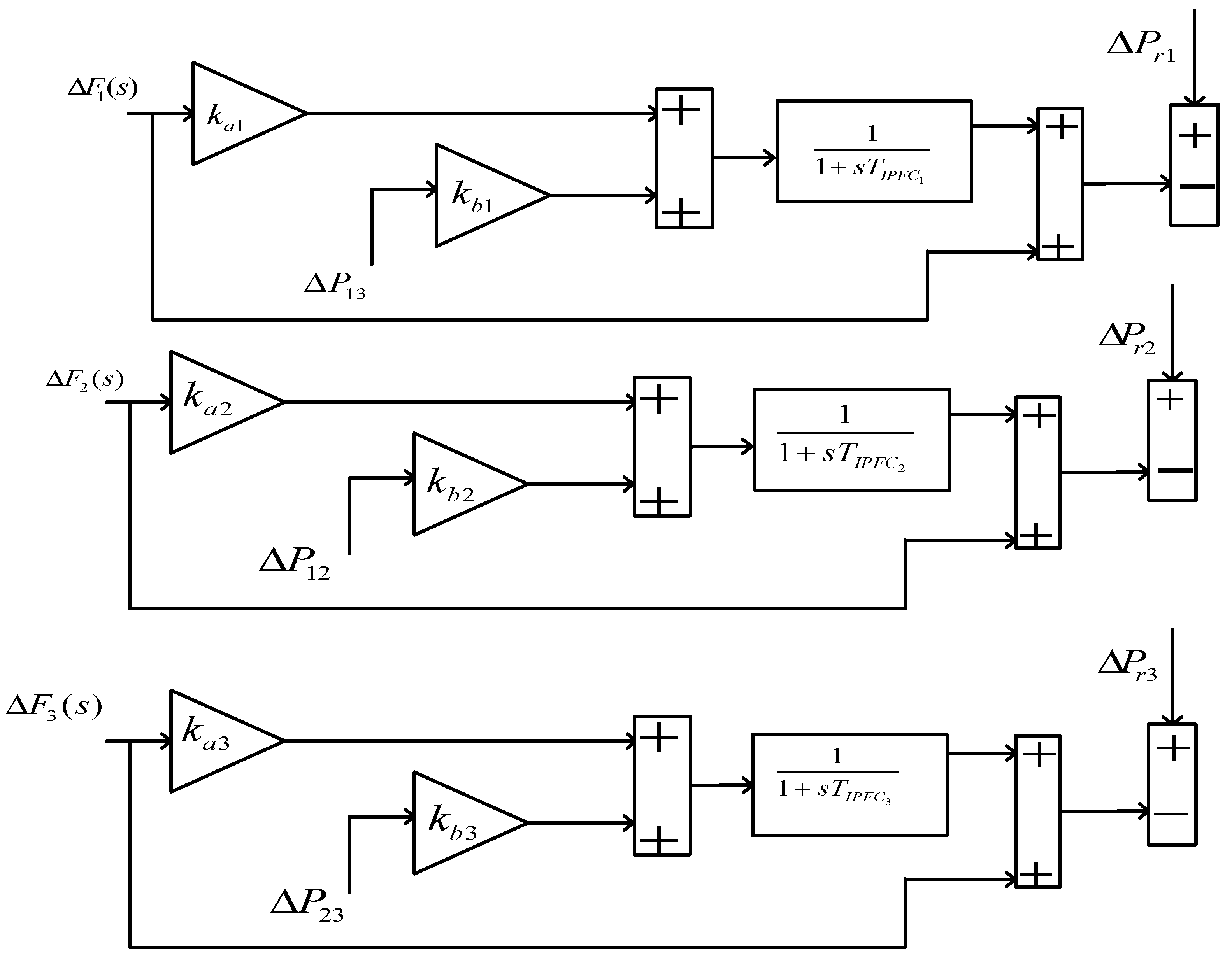
The IPFC gain parameter constants of ka and kb are connected in series with tie-line power and frequency, respectively. The complete model of IPFC is given in Figure 3, and its mathematical model is given in Equation (1), where ka and kb are the IPFC constants and TIPFC is the time constant.
Δ P IPFC S = 1 1 + sT IPFC k a Δ F 1 s + k b Δ P 12 s

2.4. Application of the IPFC FACTS Device

IPFC is an advancement of UPFC. Some of the applications of IPFC are as follows: Instead of using power flow control, IPFC can control multiple transmission lines for a single line. IPFC allows for active and reactive power sharing between the two lines [47,48].

2.5. Objective Function

The choice of the objective function is considered by different criteria. From the different types of objective functions, also known as cost functions such as IAE, ITSE, ITAE and ISE, the ITAE is chosen. The reason is that compared to ITSE, a smaller output is provided by ITAE than ITSE. Similarly, a reduced settling time and reduced peak overshoot are obtained in the case of the ITAE criterion [49].
In this paper, before choosing the ITAE as an objective function, a comparison analysis with other objective functions such as ITSE, ISE, and IAE was performed using time domain specification, namely the peak undershoot, peak overshoot, and settling time, as per the objective of minimizing the ACE control error using DE, which are given in Equations (2)–(5). Table 1, Table 2, Table 3 and Table 4 present the time response gain measurement values for the objective functions ITAE, IAE, ITSE, and ISE, respectively. It was found that better results were obtained by using the ITAE than the others.
ITAE = 0 t t . ACE i ( t ) dt
IAE = 0 t ACE i ( t ) dt
ITSE = 0 t t . ACE i ( t ) 2 dt
ISE = 0 t ACE i ( t ) 2 dt
The mathematical definition of ACE is given in Equation (6), which combines frequency and power exchange for an area [49].
ACE i = Δ P tie , i + β i Δ f i
In Equation (7), β i , Di, and Ri, respectively, are the frequency biasing factor, damping coefficient, and droop characteristic for ith area.
β i = 1 R i + D i

2.6. Optimization Technique

Storn and Price were the first to develop the DE algorithm [50]. The steps of the DE algorithm are the initialization of the parameters, the mutation operation, the crossover operation, and the selection operation. The flowchart of the DE optimization is shown in Figure 4.

2.6.1. Initialization

Two intervals of lower and upper bounds will be fixed during initialization, and the initial value can be generated randomly and uniformly. X J L and X J U , respectively, are the lower and upper bounds.

2.6.2. Mutation Operation

The target vector is combined with the donor vector to produce offspring in a mutation operation:
V i , G + 1 = X r 1 , G + F X r 2 , G X r 3 , G
In Equation (8), the integer numbers r1, r2, and r3 are produced at random, and F is a scaling factor that has values between 0 and 2, where V i , G = V 1 i , G , V 2 i , G , . , V Di , G .
D is the control variable or individual vector solutions, and the population size NP is in the range of [1, NP].

2.6.3. Crossover Procedure

The crossover step is used to obtain the potential diversity within the population and is given in Equation (9):
U j , i , G + 1 = { j X j , i , G ,   otherwise   V j , i , G ,   if   rand j 0 , 1 CR or j = j rand = 1 , 2 , , D
The crossover probability (CR) for this work was taken to be 0.98.

2.6.4. Selection Operation

The best fit value will be selected in the selection step for the next generation by comparing the trial and target and is given in Equation (10):
X i , G + 1 = U i , G   if   f U i , G f X i , G x i , G   otherwise
Generations = Current   gen Max   number   of   generations
F = i = 1 r F μ i F F 1 i i = 1 rF μ i F

2.7. Pseudocode of the Proposed DE Optimized Fuzzy PID Controller

Generate the initial population of individuals
Do
For each individual j in the population
C h o o s e   t h r e e   n u m b e r s   x 0 ,   x 1 ,   a n d   x 2   t h a t   i s ,   1 x 0 x 1 x 2 j
For each parameter i
Calculate generation using Equation (11)
Use a fuzzy system to calculate the new Mutation parameter using Equation (12)
v i , g = x r 0 , g + F . ( x r 1 , g x r 2 , g ) u i , g = u j , i , g v j , i , g i f r a n d j ( 0 , 1 ) C r o r j = j r a n d x j , i , g o t h e r w i s e
End for
Replace
R e p l a c e   x j , i , g   w i t h   t h e   c h i l d   u i , g   i f   u i , g i s   b e t t e r    
End for
Until the termination condition is achieved

3. Results

In this research, the dynamic performance of three equal-area power system models with a 2000 MW rating in each area was considered. To know the improvement in the dynamic performance of the system under study, the following things were considered: a MATLAB code interfacing with a Simulink model, optimization, conventional and intelligent fuzzy controllers, random load change, disturbances in each area, an IPFC FACTS device, ITAE as an objective function, etc. The values of the parameters involved in the simulation, such as number of populations (NP), scaling factor (F), number of iterations, etc., are presented in Table 5.
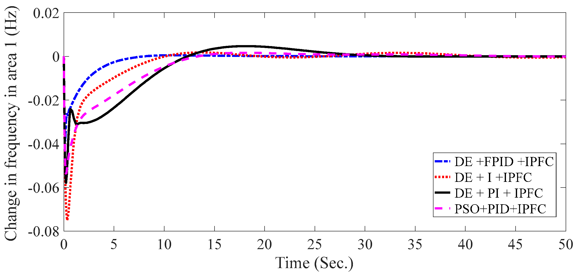
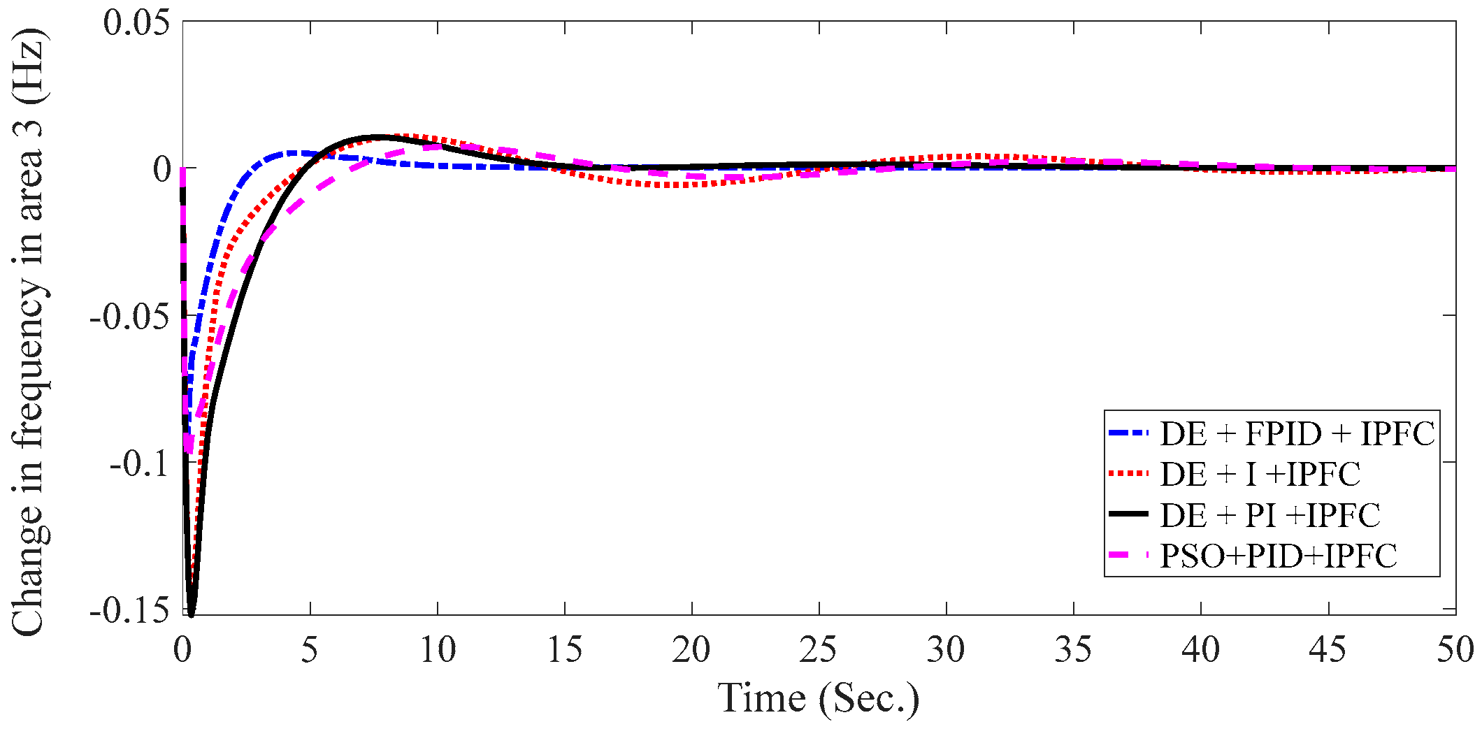
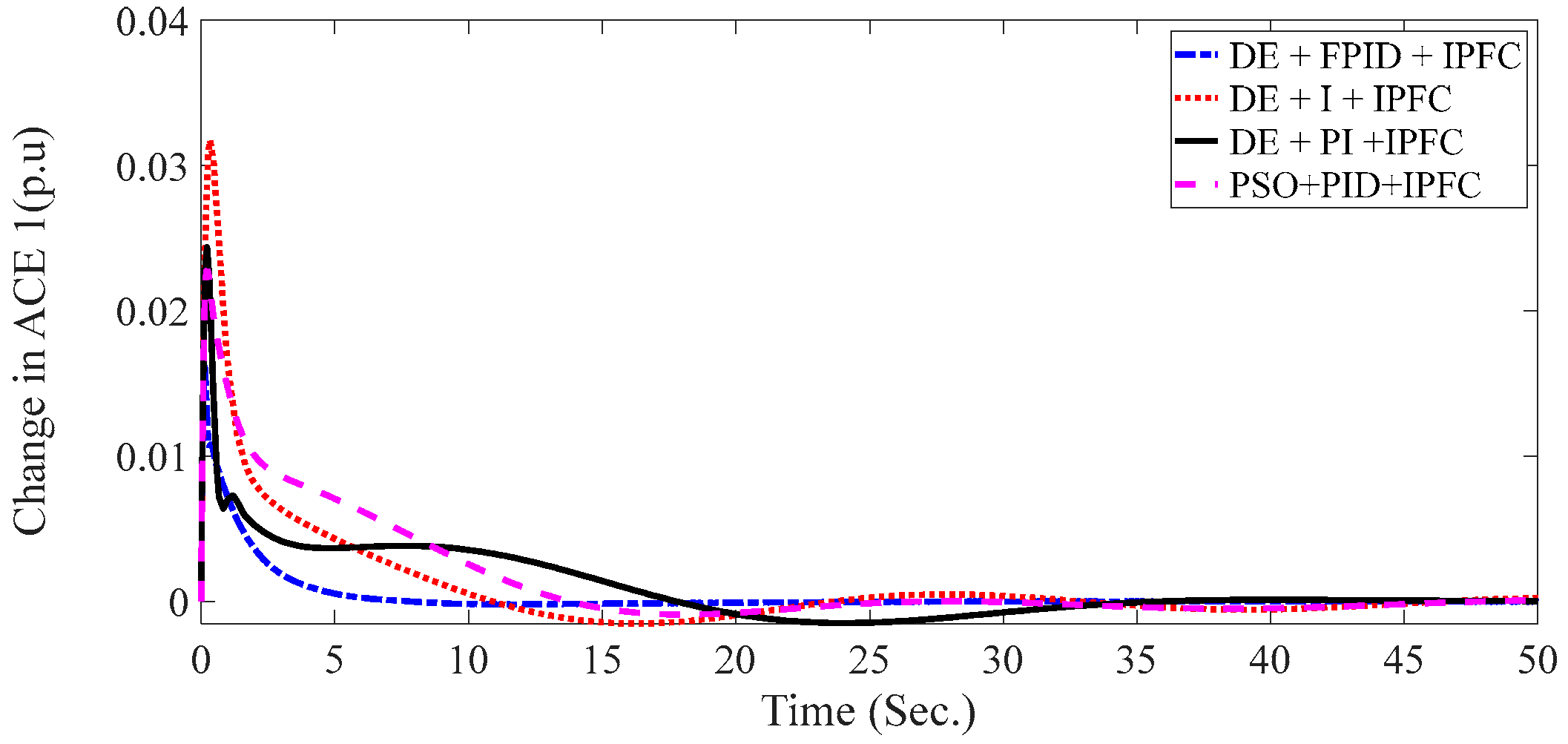
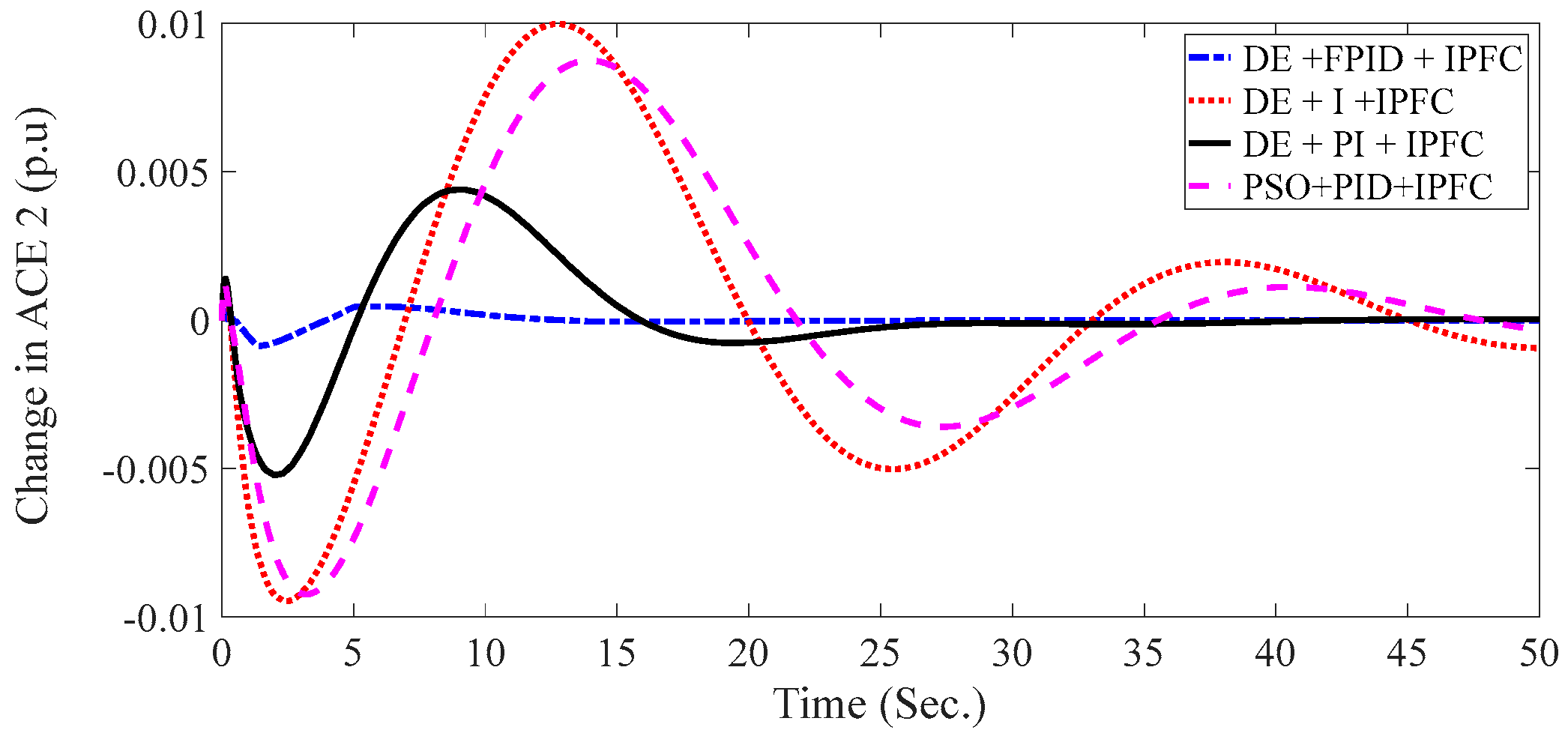
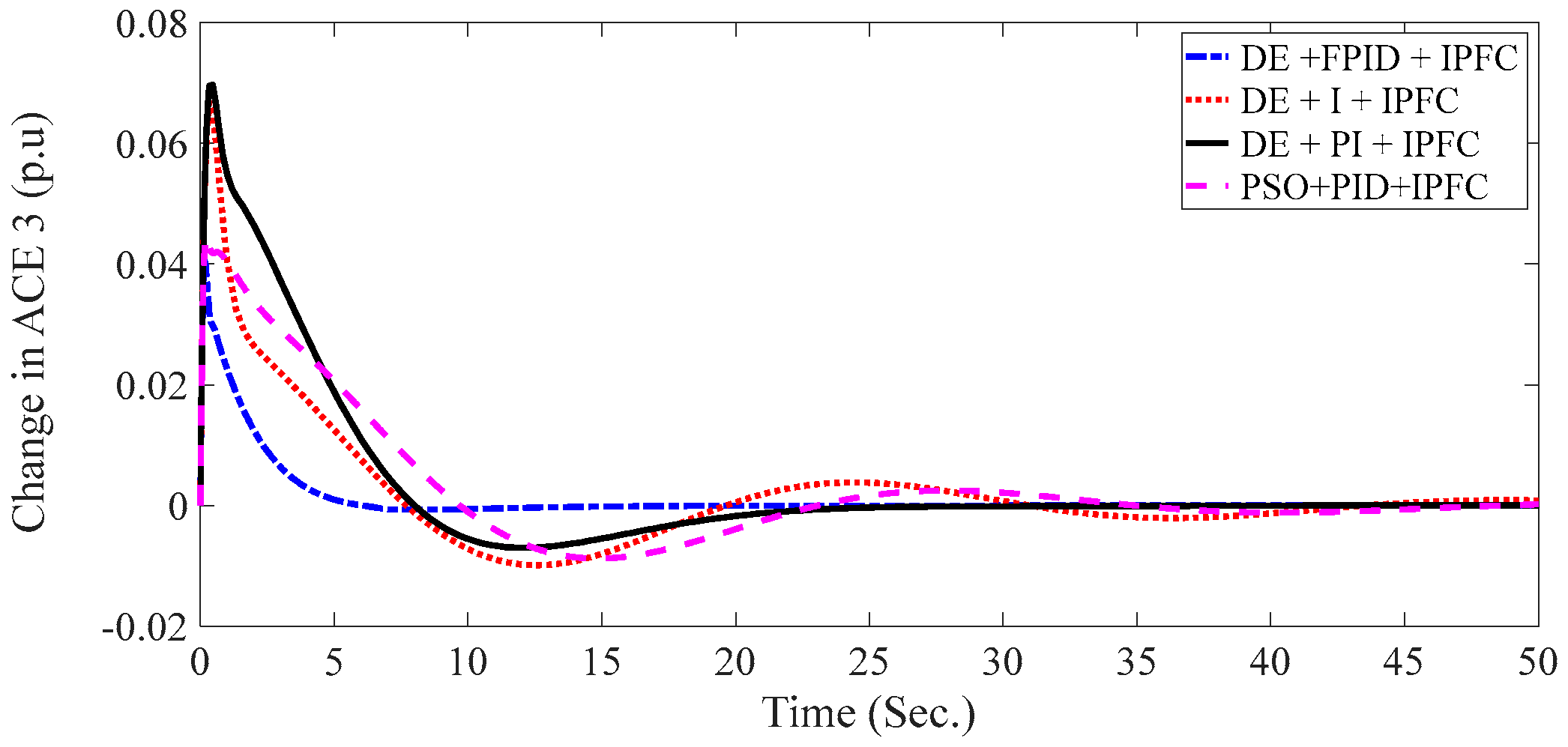
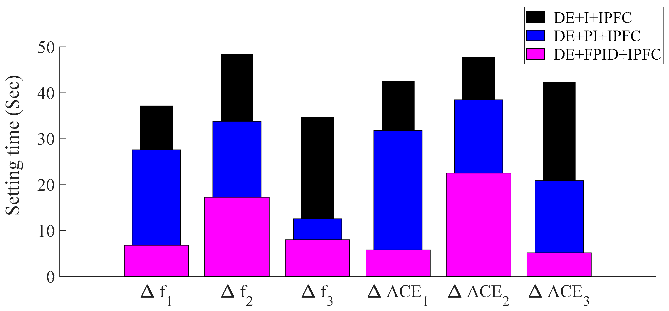
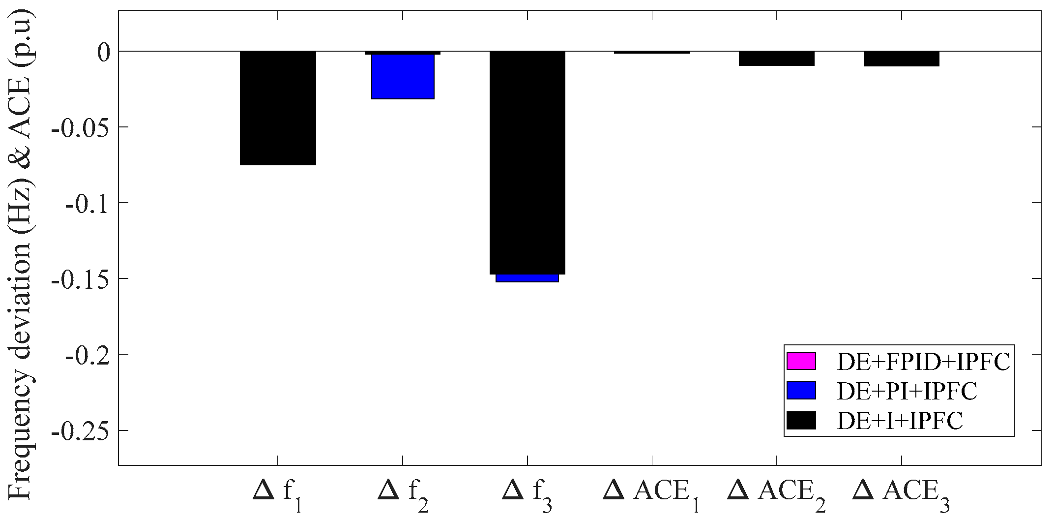
The main control parameters were the change in frequency and the change in ACE, while the main measurement parameters were the settling time, overshoot, undershoot, and rise time. Additionally, the main controllers were the integral, PI, and FPID including the IPFC FACTS device. In the optimization, the minimum solution was taken as a solution after running the program more than 30 times, and the optimization was initialized with 0 as the lower bound range and 2 as the upper bound range. Table 6, Table 7, Table 8, Table 9, Table 10 and Table 11 show the optimized gain parameters of the FPID, IPFC, I, optimized IPFC in the presence of the integral, PI. and optimized IPFC in the presence of the PI controller, respectively. The comparison of the FPID, I, and PI controllers in the presence of the IPFC with the time response parameters is given in Table 12, Table 13 and Table 14, and the FPID + IPFC with the reduced ST, OS, and US provided a satisfying result when compared with the fuzzy integral and fuzzy PI controllers. Table 15 discusses the time response results obtained by optimizing the PID with the PSO in the presence of the IPFC FACTS device. Compared to the other controllers, the reduced-error ITAE objective function was achieved in the case of the FPID controller by using the DE technique, which resulted in a value of 0.2545 pu; for the PSOPID controller in the presence of IPFC, the value was 3.2976 pu, and in the case without the controller, the value was 187.5810 pu, and these values are given in Table 16. Figure 5, Figure 6 and Figure 7 show the comparison of DE + FPID + IPFC, DE + I + IPFC, DE + PI + IPFC, and PSO + PID + IPFC for the change in frequency f1, f2, and f3, respectively, and they show that with the DE + FPID + IPFC reduced settling time, an overshoot and undershoot were achieved; similarly, Figure 8, Figure 9 and Figure 10 depict the results of the comparison of the changes in ACE1, ACE2, and ACE3, respectively, and better result were achieved with the proposed DE + FPID + IPFC controller. Compared to the other controllers, the fast convergence characteristics of the proposed controller that was created by using the DE method are given in Figure 11. The performance of the time response parameters is also shown in Figure 12, Figure 13 and Figure 14, which revealed that the FPID optimized by DE performed better with the reduced undershoot, reduced settling time, and reduced overshoot. The results of the analysis on the application of the random load change to the system is shown in Figure 15, Figure 16, Figure 17, Figure 18, Figure 19, Figure 20, Figure 21, Figure 22, Figure 23, Figure 24 and Figure 25, and the discussion for each is also given, which corresponds to each simulation result figure.
Figure 5, Figure 6 and Figure 7 depict the simulation results of the change in frequency f1, f2, and f3, respectively. These parameters were better controlled with the proposed controller DE + FPID + IPFC than with the DE optimized I and PI with the presence of IPFC. Moreover, to prove that the DE technique is better than others, a comparative study with PSO + PID + IPFC was conducted, and with the proposed controller, better results were achieved with a reduced undershoot, reduced settling time, and reduced overshoot.
Figure 8, Figure 9 and Figure 10 depict the simulation results of the change in ACE1, ACE2, and ACE3, respectively. The ACE error is a linear combination of change in the tie-line power and change in frequency. These parameters were better controlled with the proposed controller DE + FPID + IPFC than with the DE-optimized I and PI with the presence of IPFC.
Figure 11 shows the convergence characteristics of the DE-optimized proposed controller with IPFC. The DE algorithm optimized the conventional controllers such as I and PI with IPFC, and the convergence characteristics of the PSO-optimized PID with IPFC were compared; from the results, it was shown that the proposed controller converged with the fast iteration and with a smaller cost error function than the other controllers that were involved in the comparison.
Table 12, Table 13, Table 14 and Table 15 present the time response output values for DE + FPID with IPFC, DE + I with IPFC, DE + PI with IPFC, and PSO + PID with IPFC controllers, respectively. In each table, the parameters of the change in the frequency and the parameters of the change in the ACE were assessed for the time response outputs such as the settling time, undershoot, and overshoot. According to the results, compared to the other controllers, the suggested controller produced a smaller settling time, decreased undershoot, and decreased overshoot. Furthermore, PSO was also used to optimize the controller; it was compared with the proposed controller, and the superiority of DE over PSO was proved.
Comparisons of DE + FPID with IPFC, DE + I with IPFC, and DE + PI with IPFC for changes in frequency and changes in ACE are shown in Figure 12, Figure 13 and Figure 14. The findings unmistakably demonstrated that the proposed controller had a decreased settling time, reduced overshoot, and reduced undershoot.

Result Analysis for Random Load Change

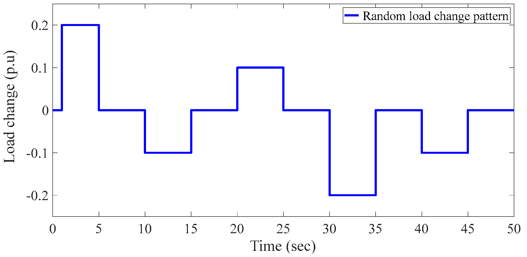
Figure 15 shows the simulation output of the random load change versus time with a 50 s simulation time for a load change ranging from [−0.2 to 0.2], which was included only to show the random load simulation output before considering the system with this load variation range. The load change can increase or decrease with time between a load of −0.2 and 0.2 pu.
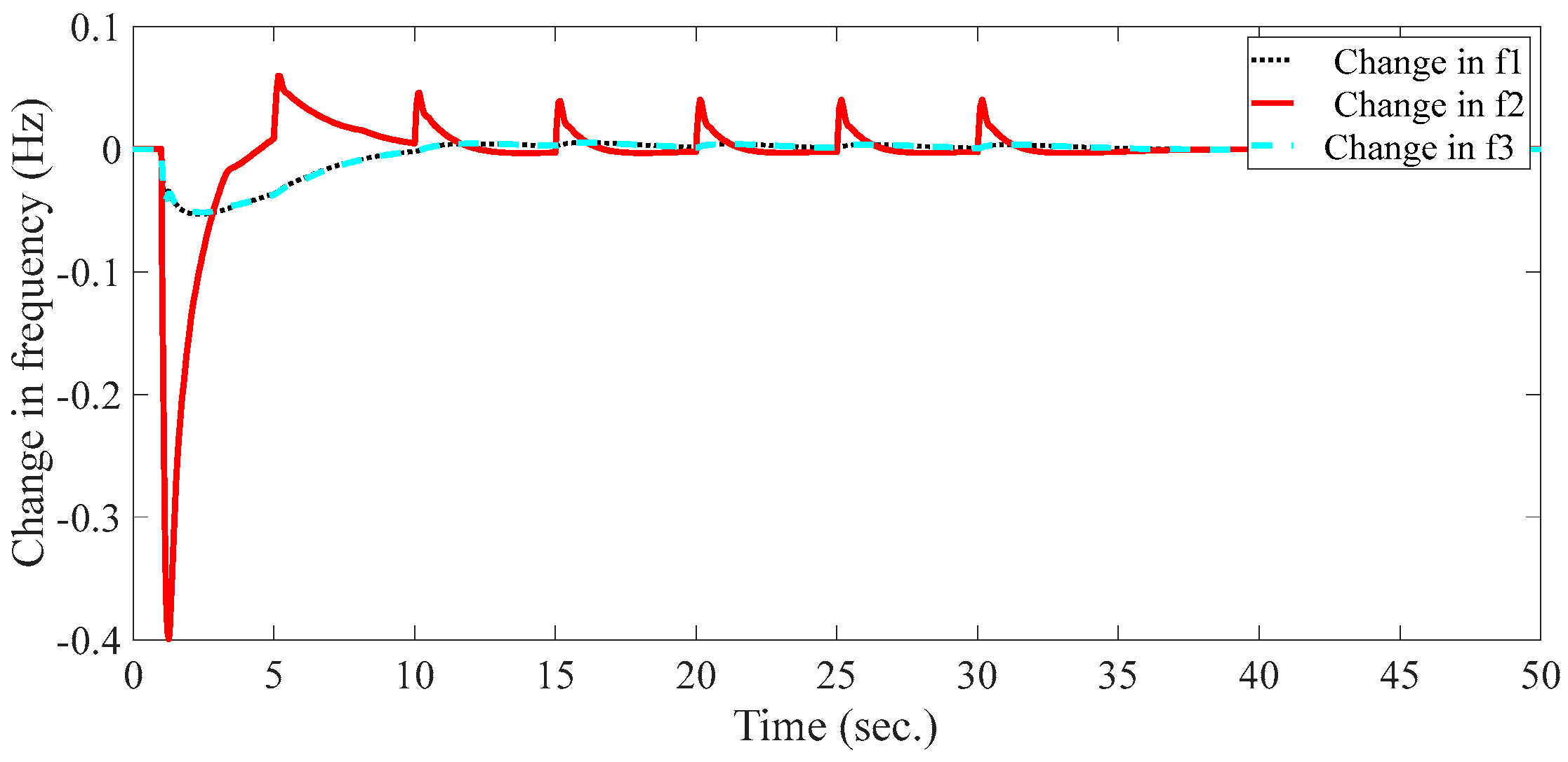
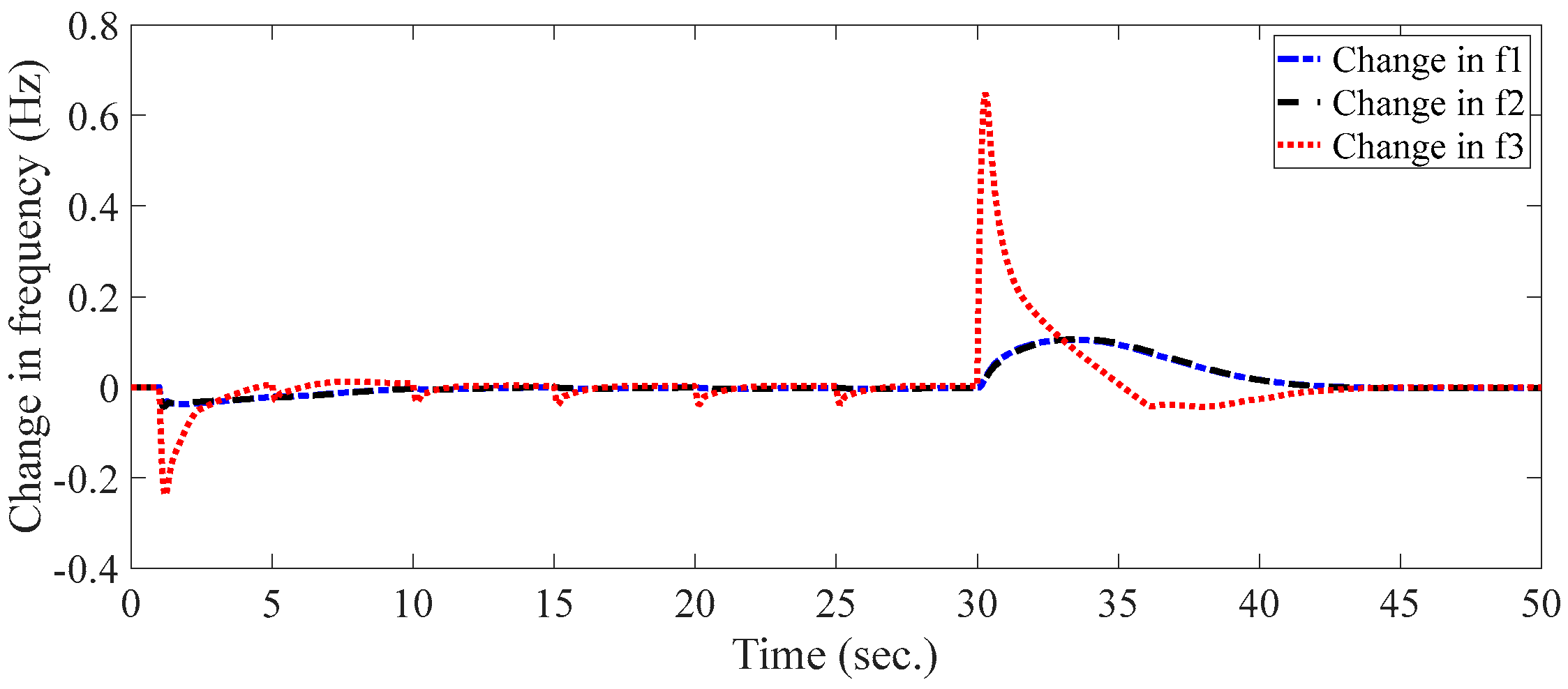
Figure 16 depicts the simulation results of the change in frequencies when random load changes were added to all areas of the system, and depending on the size of the random load change applied to the system, the output of the change frequencies also varied. As shown in Figure 16, the settling time for a change in frequency f1 was 48.5793 s, the settling time for a change in frequency f2 was 47.9958 s, and the settling time for a change in frequency f3 was 48.2853 s.
The simulation output of the change in the three frequencies showed that the output was not constant for some time before the controller was able to withstand the random load change, and the change in frequency f1 settled at 29.2976 s, the change in frequency f2 settled at 31.4428 s, and the change in frequency f3 settled at 31.7031 s and became stable.
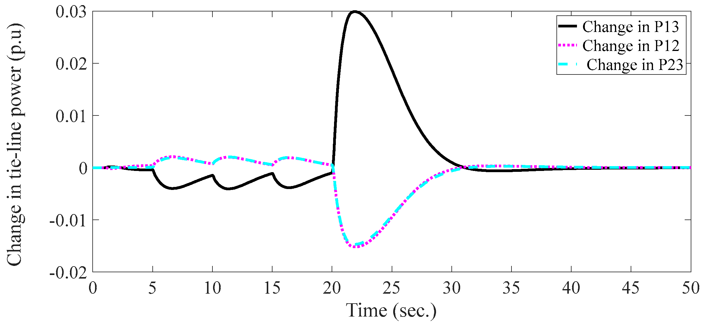
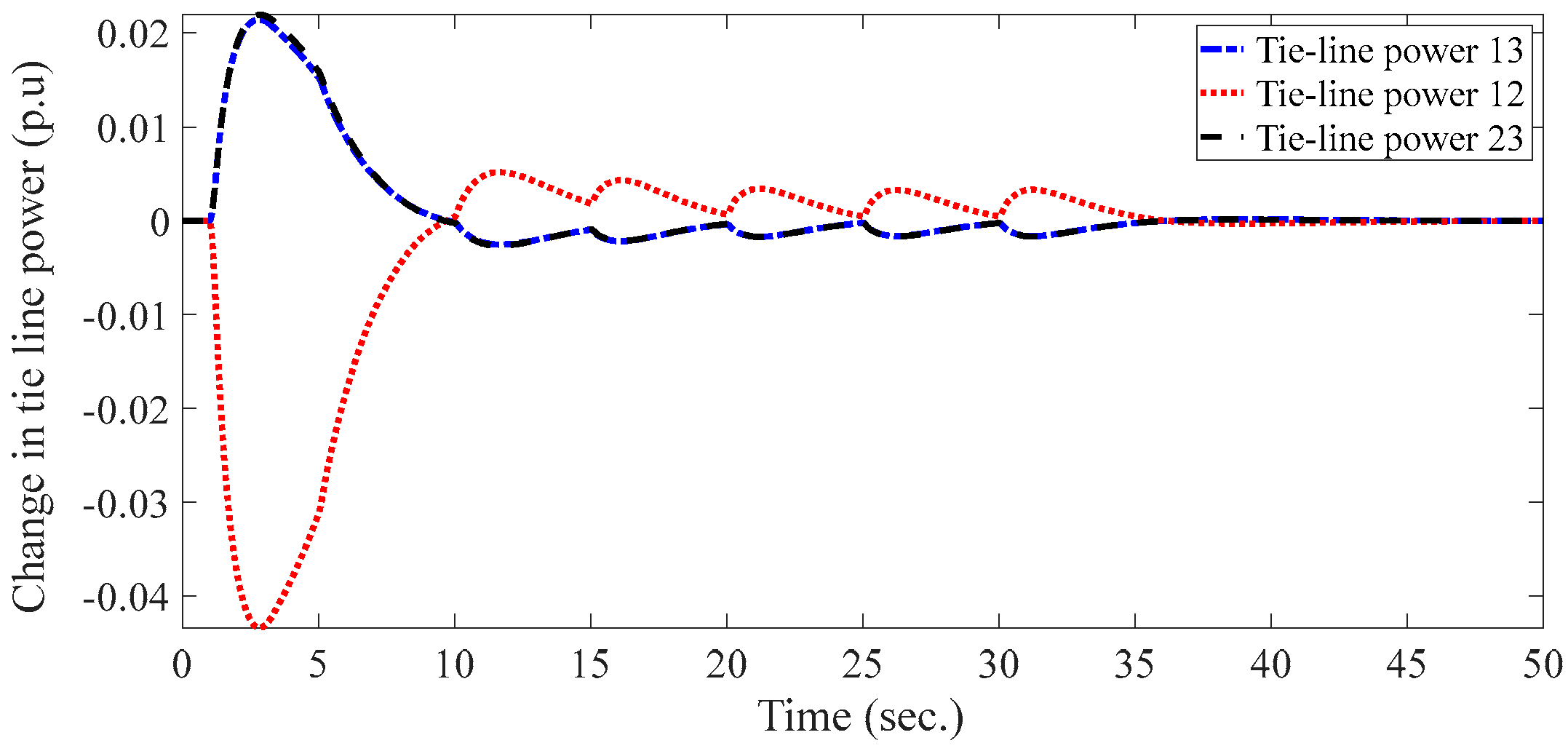
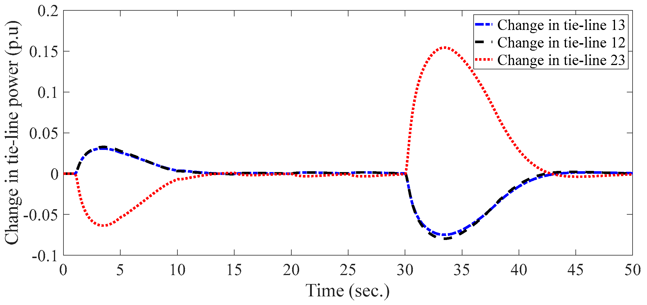
The simulation output of the change in the tie-line power revealed that the output was not constant for some time before the controller withstood the random load change, as shown in Figure 18 simulation results for a random load change that was solely applied to area 1. The change in the tie-line power P13, P12, and P23 were settled at 30.3716 s, 34.7528 s, and 30.6412 s, respectively.
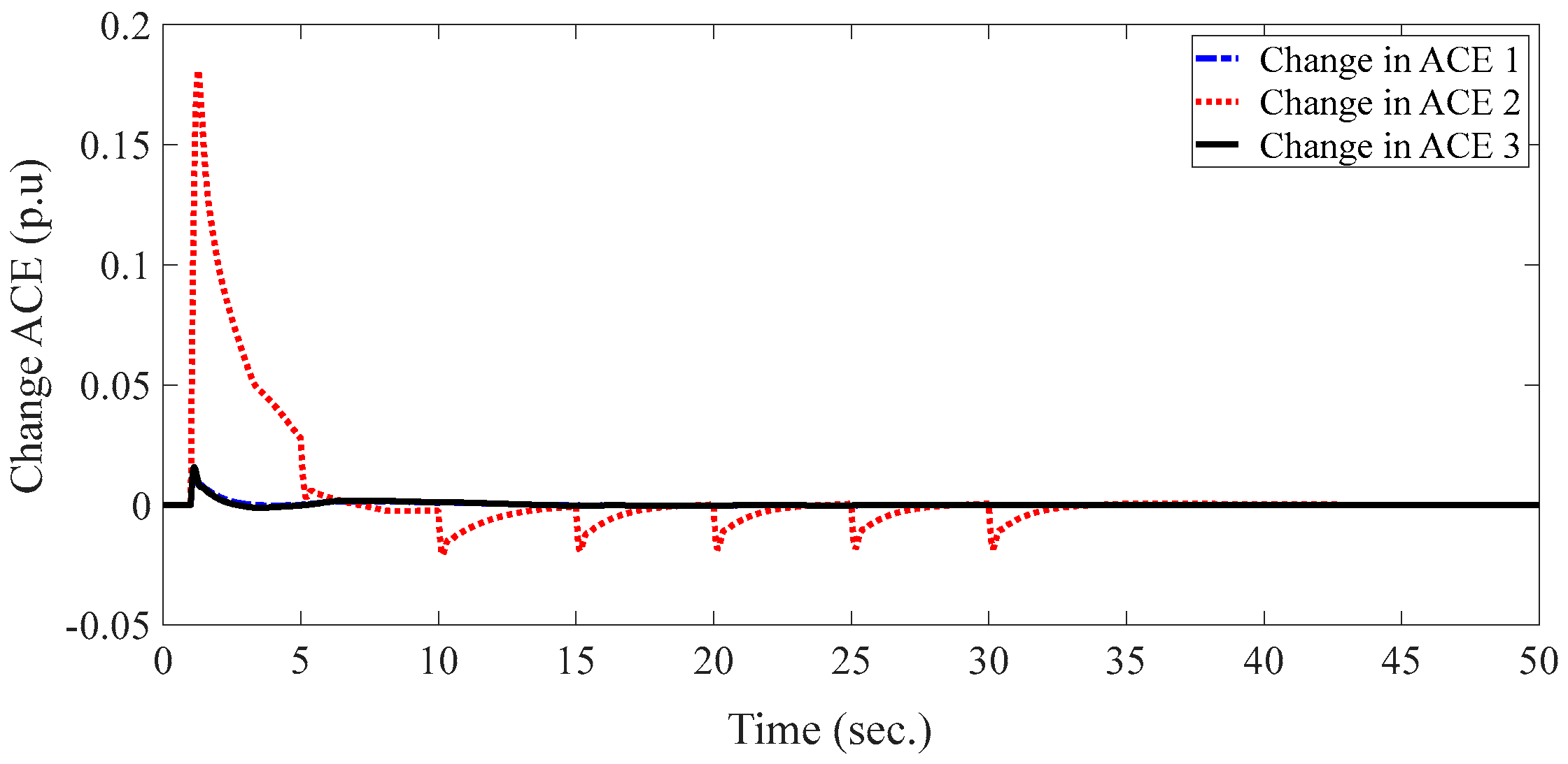
The simulation output of the change in the ACE demonstrated that the output was not constant for some time until the controller withstood the random load change, as shown in the simulation results in Figure 19. The random load variation was applied solely to area 1. ACE1 was scheduled to change every 27.4720 s, ACE2 every 32.3403 s, and ACE3 every 31.9931 s.
The random load change applied to the simulation output of Figure 20 was in area 2 only, and the simulation output of the change in the frequencies showed that the output was not constant for some time before the controller withstood the random load change. Additionally, the change in frequency f1 settled at 34.7713 s, the change in frequency f2 settled at 30.9420 s, and the change in frequency f3 settled at 34.8326 s and became stable.
Only area 2 was subjected to the random load change in Figure 21 simulation output, and the output of the tie-line power simulation revealed that the output was not constant for a while before the controller could survive the random load change. P13, P12, and P23′s tie-line power changes were fixed at 34.3899, 34.3901, and 34.3897 s, respectively.
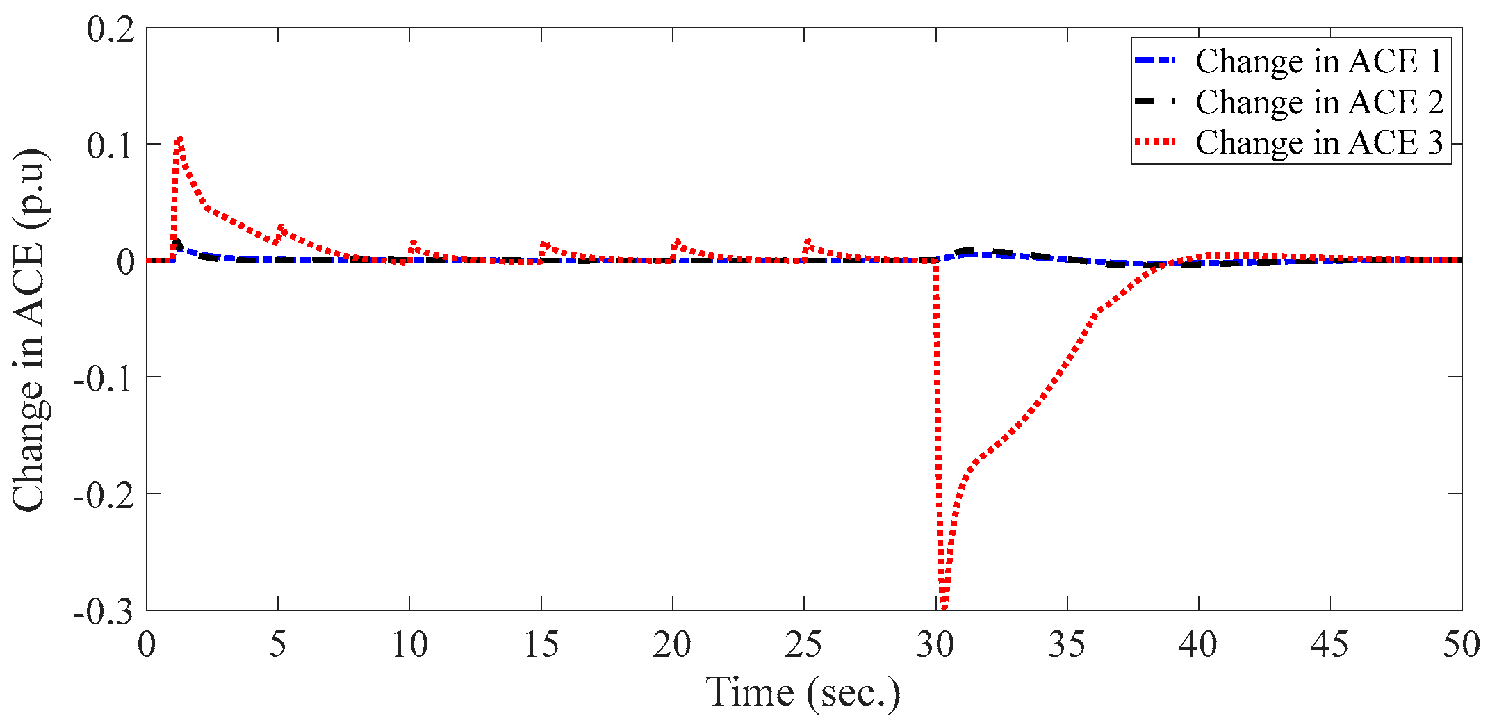
The only area in which the random load change was applied to the simulation output of Figure 22 was area 2, and the simulation output of the change in ACE revealed that the output when area 2 alone was subjected to the random load change was not constant for a period of time before the controller was able to withstand the change. ACE1 was settled at 20.0098 s, ACE2 was settled at 31.5636 s, and ACE3 was settled at 20.0163 s.
The simulation output of the change in frequencies showed that the output was not constant for some time before the controller withstood the random load change, and the change in frequency f1 settled at 42.8276 s, the change in frequency f2 settled at 42.3823 s, and the change in frequency f3 settled at 41.3359 s and became stable. The simulation result obtained in Figure 23 resulted from a random load change applied in area 3 only.
The simulation output of ∆P revealed that the output was not constant for some time before the controller was able to endure the random load shift, according to the simulation result shown in Figure 24. The change in the tie-line power P13, P12, and P23 were settled at 41.5292 s, 45.2672 s, and 44.5031 s, respectively.
The simulation output of ∆ACE demonstrated that the output was not constant for some time before the controller withstood the random load change, according to the simulation result shown in Figure 25. The change in ACE1, ACE2, and ACE3 were settled at 46.1174 s, 45.5326 s, and 38.4988 s, respectively.

4. Discussion

By taking into account three case studies, the performance of the controllers on the system for random load fluctuations from 0.1 to 0.9 p.u. was examined. Figure 15 shows the result of the system’s simulation with a random load change pattern in the beginning, which involved 50 s of variable load from −0.2 to 0.2. In Figure 16, the effect of varying the frequency output as a result of the application of the random load change was observed. And, it was shown that when there was an increase in the load, the frequency dropped and vice versa. The simulation results of the random load changes for the three case studies are given in Figure 17, Figure 18, Figure 19, Figure 20, Figure 21, Figure 22, Figure 23, Figure 24 and Figure 25.
The simulation results for ∆f, ∆P, and ∆ACE are shown in Figure 17, Figure 18 and Figure 19, respectively. In case 1, a random step load disturbance from 0.1 p.u to 0.4 p.u for 50 s in area 1 is taken into account while 0.1 p.u is kept for areas 2 and 3. The result showed that in all cases, for a certain time, the system showed a varying output, and after some time, the system achieved its steady state, which revealed the effectiveness of the proposed controller.
In case 2, a random load shift in area 2 from 0.6 to 0.1 p.u for 50 s was taken into account, while area 1 and area 3 were kept at 0.1 p.u SLP. The results of the simulation regarding the changes in frequency, tie-line power, and ACE are presented in Figure 20, Figure 21 and Figure 22, respectively. It was also demonstrated that the system eventually reached its steady-state value.
In case 3, a random load change was applied to area 3 for fifty seconds from 0.4 to 0.9 p.u, whereby the load of area 1 and area 2 was kept constant at 0.1, and this large varying load critically affected the measured parameters compared to case 1 and case 2. Figure 23, Figure 24 and Figure 25 show the produced simulation results for the frequency change, planned tie-line power change, and ACE change, respectively. Here, even with a huge disturbance, the system stabilized after 40 s on average, indicating that the suggested controller was sufficient to keep the system under control even with a large disturbance.

5. Conclusions

In order to improve the multiarea AGC system’s capacity for power regulation and to make the controller more practical and suited for optimization, this research compares intelligent and traditional controllers such as integral and PI controllers. The proposed DE + FPID + IPFC with a reduced ST, OS, and US achieved a change in the frequency and a change in the ACE. The fuzzy PID model was used in this work, and the parameters of both the fuzzy controller and the PID, I, and PI controller were optimized by using DE and PSO techniques. The results of each controller with the IPFC FACTS device are shown in Figure 6, Figure 7, Figure 8, Figure 9, Figure 10, Figure 11, Figure 12, Figure 13, Figure 14 and Figure 15 and in Table 12, Table 13, Table 14 and Table 15.
To prove that the DE optimization method is the proper choice for optimizing controllers, the DE optimization method was compared with the PSO technique, and the results showed the superiority of the DE method. Moreover, when we compared the ITAE error values without a controller, the proposed FPID + IPFC with DE, and PSO + PID with IPFC, the values were 187.5810 pu, 0.2545 pu, and 3.2976 pu, respectively, which reveals that the proposed controller was strong enough to control the system even in the presence of large disturbances. In various situations or conditions, the system is subjected to random changes in load that range from 0.1 to 0.9. We concluded that the suggested controller with IPFC can readily dampen system oscillations and endure any random load disturbance.

Author Contributions

Methodology, S.F., D.A. and M.A. (Mohamed Abuagreb); Software, S.F., D.A. and M.A. (Mohammed Alharbi); Validation, S.F., M.A. (Mohammed Alharbi) and M.A. (Mohamed Abuagreb); Formal analysis, B.P. and M.A. (Mohammed Alharbi); Investigation, B.P. and M.A. (Mohamed Abuagreb); Resources, B.P. and H.K.; Data curation, R.S.; Writing—original draft, R.S.; Writing—review & editing, R.S. and K.M.A.; Visualization, D.A. and H.K.; Supervision, K.M.A. and H.K.; Funding acquisition, K.M.A. All authors have read and agreed to the published version of the manuscript.

Funding

This research received no external funding.

Institutional Review Board Statement

Not applicable.

Informed Consent Statement

Not applicable.

Data Availability Statement

The data sources employed for analysis are presented in the text.

Acknowledgments

This work was supported by the Researchers Supporting Project number (RSP2023R467), King Saud University, Riyadh, Saudi Arabia.

Conflicts of Interest

The authors declare no conflict of interest.

References

  1. Saini, J.S.; Jain, V. A genetic algorithm optimised fuzzy logic controller for automatic generation control for single area system. J. Inst. Eng. 2015, 96, 1–8. [Google Scholar] [CrossRef]
  2. Ullah, K.; Basit, A.; Ullah, Z.; Aslam, S.; Herodotou, H. Automatic generation control strategies in conventional and modern power systems: A comprehensive overview. Energies 2021, 14, 2376. [Google Scholar] [CrossRef]
  3. Hamodat, Z.; Cansever, G. Automated Generation Control of Multiple-Area Electrical System with an Availability-Based Tariff Pricing Scheme Regulated by Whale Optimized Fuzzy PID Controller. Int. J. Photoenergy 2021, 2021, 5596527. [Google Scholar] [CrossRef]
  4. Feleke, S.; Satish, R.; Tatek, W.; Abdelaziz, A.Y.; El-Shahat, A. DE-Algorithm-Optimized Fuzzy-PID Controller for AGC of Integrated Multi Area Power System with Link. Energies 2022, 15, 6174. [Google Scholar] [CrossRef]
  5. Kocaarslan, I.; Çam, E. Fuzzy logic controller in interconnected electrical power Systems for load-frequency control. Int. J. Electr. Power Energy Syst. 2005, 27, 542–549. [Google Scholar] [CrossRef]
  6. Golpira, H.; Bevrani, H. Application of GA optimization for automatic generation control design in an interconnected power system. Energy Convers. Manag. 2011, 52, 2247–2255. [Google Scholar] [CrossRef]
  7. Kumar, D.M.V. Intelligent controllers for automatic generation control. In Proceedings of the IEEE TENCON’98. IEEE Region 10 International Conference on Global Connectivity in Energy, Computer, Communication and Control, New Delhi, India, 17–19 December 1998; Volume 2, pp. 557–574. [Google Scholar]
  8. Sinha, S.K.; Patel, R.N.; Prasad, R. Applications of FACTS devices with Fuzzy controller for oscillation damping in AGC. In Proceedings of the 2011 International Conference on Recent Advancements in Electrical, Electronics and Control Engineering, Sivakasi, India, 5–17 December 2011; pp. 314–318. [Google Scholar]
  9. Pilla, R.; Azar, A.T.; Gorripotu, T.S. Impact of flexible AC transmission system devices on automatic generation control with a metaheuristic based fuzzy PID controller. Energies 2019, 12, 4193. [Google Scholar] [CrossRef] [Green Version]
  10. Alhelou, H.H.; Hamedani-Golshan, M.E.; Zamani, R.; Heydarian-Forushani, E.; Siano, P. Challenges and opportunities of load frequency control in conventional, modern and future smart power systems: A comprehensive review. Energies 2018, 11, 2497. [Google Scholar] [CrossRef] [Green Version]
  11. Yesil, E.; Demiroren, A.; Yesil, E. Automatic Generation Control with Fuzzy Logic Controller in the Power System Including Three Areas; Department of Electrical Engineering Electric & Electronic Faculty Istanbul Technical University: Istanbul, Turkey, 2001. [Google Scholar]
  12. Sahu, B.K.; Pati, S.; Panda, S. Hybrid differential evolution particle swarm optimization optimised fuzzy proportional–integral derivative controller for automatic generation control of interconnected power system. IET Gener. Transm. Distrib. 2014, 8, 1789–1800. [Google Scholar] [CrossRef]
  13. Debnath, M.K.; Jena, T.; Mallick, R.K. Optimal design of PD-Fuzzy-PID Cascaded controller for automatic generation control. Cogent Eng. 2017, 4, 1416535. [Google Scholar] [CrossRef]
  14. Nayak, C.; Prusty, R.C.; Panda, S. Grasshopper optimization algorithm optimized multistage controller for automatic generation control of a power system with FACTS devices. Prot. Control Mod. Power Syst. 2021, 6, 8. [Google Scholar] [CrossRef]
  15. Debnath, M.K.; Mallick, R.K.; Sahu, B.K. Application of hybrid differential evolution–grey wolf optimization algorithm for automatic generation control of a multi-source interconnected power system using optimal fuzzy–PID controller. Electr. Power Compon. Syst. 2017, 45, 2104–2117. [Google Scholar] [CrossRef]
  16. Bevrani, H.; Daneshmand, R. Fuzzy logic-based load-frequency control concerning high penetration of wind turbines. IEEE Syst. J. 2011, 6, 173–180. [Google Scholar] [CrossRef]
  17. Nanda, J.; Mishra, S.; Saikia, L.C. Maiden application of bacterial foraging-base optimization technique in multiarea automatic generation control. IEEE Trans. Power Syst. 2009, 24, 602–609. [Google Scholar] [CrossRef]
  18. Kumar, P.; Kothari, D.P. Recent philosophies of automatic generation control strategies in power systems. IEEE Trans. Power Syst. 2005, 20, 346–357. [Google Scholar]
  19. Lal, D.K.; Barisal, A.K. Comparative performances evaluation of FACTS devices on AGC with diverse sources of energy generation and SMES. Cogent Eng. 2017, 4, 1318466. [Google Scholar] [CrossRef]
  20. Chen, G.; Li, Z.; Zhang, Z.; Li, S. An improved ACO algorithm optimized fuzzy PID controller for load frequency control in multi area interconnected power systems. IEEE Access 2019, 8, 6429–6447. [Google Scholar] [CrossRef]
  21. Saikia, L.C.; Nanda, J.; Mishra, S. Performance comparison of several classical controllers in AGC for multi-area interconnected thermal system. Int. J. Electr. Power Energy Syst. 2011, 33, 394–401. [Google Scholar] [CrossRef]
  22. Abdelaziz, A.Y.; Ali, E.S. Static VAR Compensator Damping Controller Design Based on Flower Pollination Algorithm for a Multi-machine Power System. Electr. Power Compon. Syst. 2015, 43, 1268–1277. [Google Scholar] [CrossRef]
  23. Abdelaziz, A.Y.; Ali, E.S. Load Frequency Controller Design via Artificial Cuckoo Search Algorithm. Electr. Power Compon. Syst. 2016, 44, 90–98. [Google Scholar] [CrossRef]
  24. Fathy, A.; Kassem, A.M.; Abdelaziz, A.Y. Optimal design of fuzzy PID controller for deregulated LFC of multi-area power system via mine blast algorithm. Neural Comput. Appl. 2020, 32, 4531–4551. [Google Scholar] [CrossRef]
  25. Ebrahim, M.A.; Becherif, M.; Abdelaziz, A.Y. PID/FOPID-based frequency control of zero-carbon multisources-based interconnected power systems under deregulated scenarios. Int. Trans. Electr. Energy Syst. 2021, 31, e12712. [Google Scholar]
  26. Sahoo, D.K.; Sahu, R.K.; Sekhar, G.C.; Panda, S. A novel modified differential evolution algorithm optimized fuzzy proportional integral derivative controller for loadfrequency control with thyristor controlled series compensator. J. Electr. Syst. Inf. Technol. 2018, 5, 944–963. [Google Scholar]
  27. Mohanty, B.; Hota, K.; Paikray, A. Performance evaluation of differential evolution algorithm on automatic generation control. In Proceedings of the 2014 International Conference on Circuits, Power and Computing Technologies [ICCPCT-2014], Nagercoil, India, 20–21 March 2014; pp. 763–768. [Google Scholar]
  28. Mohanty, B.; Panda, S.; Hota, K. Differential evolution algorithm based automatic generation control for interconnected power systems with non-linearity. Alex. Eng. J. 2014, 53, 537–552. [Google Scholar] [CrossRef] [Green Version]
  29. Mohanty, P.; Sahu, R.K.; Sahoo, D.K.; Panda, S. Adaptive differential evolution and pattern search tuned fractional order fuzzy PID for frequency control of power systems. Int. J. Model. Simul. 2022, 42, 240–254. [Google Scholar] [CrossRef]
  30. Wong, W.K.; Ming, C.I. A review on metaheuristic algorithms: Recent trends, benchmarking and applications. In Proceedings of the 2019 7th International Conference on Smart Computing & Communications (ICSCC), Sarawak, Malaysia, 28–30 June 2019; pp. 1–5. [Google Scholar]
  31. Kavitha, K.; Neela, R. Optimal allocation of multi-type FACTS devices and its effect in enhancing system security using BBO, WIPSO & PSO. J. Electr. Syst. Inf. Technol. 2018, 5, 777–793. [Google Scholar]
  32. Ramjug-Ballgobin, R.; Ramlukon, C. A hybrid metaheuristic optimisation technique for load frequency control. SN Appl. Sci. 2021, 3, 547. [Google Scholar] [CrossRef]
  33. Dash, P.; Saikia, L.C.; Sinha, N. AGC of a multi-area interconnected system with FACTS and firefly optimized 2DOF PID controller. In Proceedings of the 2014 International Conference on Control, Instrumentation, Energy and Communication (CIEC), Calcutta, India, 31 January–2 February 2014; pp. 397–401. [Google Scholar]
  34. Fathollahi-Fard, A.M.; NiazAzari, M.; Hajiaghaei-Keshteli, M. An improved red deer algorithm for addressing a direct current brushless motor design problem. Sci. Iran. 2021, 28, 1750–1764. [Google Scholar]
  35. Khadanga, R.K.; Kumar, A.; Panda, S. A modified Grey Wolf Optimization with Cuckoo Search Algorithm for load frequency controller design of hybrid power system. Appl. Soft Comput. 2022, 124, 109011. [Google Scholar] [CrossRef]
  36. Yu, H.; Dai, H.; Tian, G.; Wu, B.; Xie, Y.; Zhu, Y.; Zhang, T.; Fathollahi-Fard, A.M.; He, Q.; Tang, H. Key technology and application analysis of quick coding for recovery of retired energy vehicle battery. Renew. Sustain. Energy Rev. 2021, 135, 110129. [Google Scholar] [CrossRef]
  37. Fard, A.F.; Hajiaghaei-Keshteli, M. Red Deer Algorithm (RDA); a new optimization algorithm inspired by Red Deers’ mating. In Proceedings of the International Conference on Industrial Engineering, Bali Nusa Dua, Indonesia, 4–7 December 2016; Volume 12, pp. 331–342. [Google Scholar]
  38. Fathollahi-Fard, A.M.; Hajiaghaei-Keshteli, M.; Tavakkoli-Moghaddam, R. The social engineering optimizer (SEO). Eng. Appl. Artif. Intell. 2018, 72, 267–293. [Google Scholar] [CrossRef]
  39. Magzoub, M.A.; Alquthami, T. Optimal Design of Automatic Generation Control Based on Simulated Annealing in Interconnected Two-Area Power System Using Hybrid PID—Fuzzy Control. Energies 2022, 15, 1540. [Google Scholar] [CrossRef]
  40. Kumar, V.; Sharma, V.; Naresh, R. Leader Harris Hawks algorithm based optimal controller for automatic generation control in PV-hydro-wind integrated power network. Electr. Power Syst. Res. 2023, 214, 108924. [Google Scholar] [CrossRef]
  41. Sahu, P.R.; Simhadri, K.; Mohanty, B.; Hota, P.K.; Abdelaziz, A.Y.; Albalawi, F.; Ghoneim, S.S.; Elsisi, M. Effective Load Frequency Control of Power System with Two-Degree Freedom Tilt-Integral-Derivative Based on Whale Optimization Algorithm. Sustainability 2023, 15, 1515. [Google Scholar] [CrossRef]
  42. Shah, P.; Agashe, S. Review of fractional PID controller. Mechatronics 2016, 38, 29–41. [Google Scholar] [CrossRef]
  43. Saadatmand, M.; Mozafari, B.; Gharehpetian, G.B.; Soleymani, S. Optimal coordinated tuning of power system stabilizers and wide-area measurement-based fractional-order PID controller of large-scale PV farms for LFO damping in smart grids. Int. Trans. Electr. Energy Syst. 2021, 31, e12612. [Google Scholar] [CrossRef]
  44. Morsali, J.; Zare, K.; Hagh, M.T. A novel dynamic model and control approach for SSSC to contribute effectively in AGC of a deregulated power system. Int. J. Electr. Power Energy Syst. 2018, 95, 239–253. [Google Scholar] [CrossRef]
  45. Kundur, P. Power System Stability and Control; McGraw-Hill: New York, NY, USA, 1994. [Google Scholar]
  46. Padhan, S.; Sahu, R.K.; Panda, S. Automatic generation control with thyristor controlled series compensator including superconducting magnetic energy storage units. Ain Shams Eng. J. 2014, 5, 759–774. [Google Scholar] [CrossRef] [Green Version]
  47. Lee, C.H.; Chang, F.K. Fractional order PID controller optimization via improved electromagnetism-like algorithm. Expert Syst. Appl. 2010, 37, 8871–8878. [Google Scholar] [CrossRef]
  48. Gurijala, S.B.; Kishore, D.R.; Nittala, R.; Godala, R.R. Stability analysis and efficiency improvement of IPFC using latest PR controller. Arch. Electr. Eng. 2021, 70, 615–630. [Google Scholar]
  49. Bevrani, H. Robust Power System Frequency Control; Springer: New York, NY, USA, 2014. [Google Scholar]
  50. Storn, R.; Price, K. Differential evolution—A simple and efficient heuristic for global optimization over continuous spaces. J. Glob. Optim. 1997, 11, 341–359. [Google Scholar] [CrossRef]
Figure 1. Three-area power system model.
Sustainability 15 05625 g001
Figure 2. Structure of the proposed FPID controller.
Sustainability 15 05625 g002
Figure 3. Model of IPFC controller.
Sustainability 15 05625 g003
Figure 4. DE optimization technique flowchart.
Sustainability 15 05625 g004
Figure 5. Frequency change f1 in area 1.
Sustainability 15 05625 g005
Figure 6. Frequency change f2 in area 2.
Sustainability 15 05625 g006
Figure 7. Frequency change f3 in area 3.
Sustainability 15 05625 g007
Figure 8. ACE 1 change.
Sustainability 15 05625 g008
Figure 9. ACE 2 change.
Sustainability 15 05625 g009
Figure 10. ACE 3 change.
Sustainability 15 05625 g010
Figure 11. Convergence characteristics comparison.
Sustainability 15 05625 g011
Figure 12. Settling time comparison using conventional and intelligent controllers with IPFC for change in frequency and ACE.
Sustainability 15 05625 g012
Figure 13. Undershoot comparison using conventional and intelligent controllers with IPFC for change in frequency and ACE.
Sustainability 15 05625 g013
Figure 14. Overshoot comparison using conventional and intelligent controllers with IPFC for change in frequency and ACE.
Sustainability 15 05625 g014
Figure 15. A load change pattern ranging from [−0.2 to 0.2].
Sustainability 15 05625 g015
Figure 16. Frequency responses due to a random load change.
Sustainability 15 05625 g016
Figure 17. Frequency changes in each area for random load changes in area 1 only.
Sustainability 15 05625 g017
Figure 18. Tie-line power changes in each area for random load changes in area 1 only.
Sustainability 15 05625 g018
Figure 19. ACE changes in each area for random load changes in area 1 only.
Sustainability 15 05625 g019
Figure 20. Frequency changes in each area for random load changes in area 2 only.
Sustainability 15 05625 g020
Figure 21. Only area 2 experienced tie-line power adjustments for random load changes.
Sustainability 15 05625 g021
Figure 22. Only area 2 saw ACE fluctuations due to random load changes.
Sustainability 15 05625 g022
Figure 23. Frequency changes in each area for random load changes in area 3 only.
Sustainability 15 05625 g023
Figure 24. Only area 3 tie-line power adjustments for random load changes.
Sustainability 15 05625 g024
Figure 25. Only area 3 ACE adjustments for random load changes.
Sustainability 15 05625 g025
Table 1. Time response gain measurement values in the presence of ITAE objective functions using the proposed DE + FPID + IPFC controller.
Measured VariablesSTUndershootOvershoot
Change in f16.7617−3.8265 × 10−55.4968 × 10−4
Change in f217.26371.6677 × 10−65.8157 × 10⁻⁴
Change in f37.98508.0628 × 10−70.0050
Change in ACE 15.8068−2.2097 × 10−41.4023 × 10−5
Change in ACE 222.5019−8.7180 × 10−48.6894 × 10−4
Change in ACE 35.1147−6.9653 × 10−40.0405
Table 2. Time response gain measurement values in the presence of IAE objective functions using the proposed DE + FPID + IPFC controller.
Measured VariablesSTUndershootOvershoot
Change in f148.2105−0.1438−0.1295
Change in f248.1890−0.1519−0.1369
Change in f348.1854−0.1439−0.0527
Change in ACE 138.27520.06970.0776
Change in ACE 249.34030.05530.0613
Change in ACE 349.80660.04430.0623
Table 3. Time response gain measurement values in the presence of ITSE objective functions using the proposed DE + FPID + IPFC controller.
Measured VariablesSTUndershootOvershoot
Change in f116.31380.02610.0313
Change in f218.97930.02740.0317
Change in f316.07150.02730.0515
Change in ACE 131.8431−0.0193−0.0168
Change in ACE 236.9310−0.0191−0.0173
Change in ACE 311.5256−0.0194−0.0169
Table 4. Time response gain measurement values in the presence of ISE objective functions using the proposed DE + FPID + IPFC controller.
Measured VariablesSTUndershootOvershoot
Change in f149.8408−0.02300.0483
Change in f249.7914−0.05050.0621
Change in f349.7394−0.05530.0794
Change in ACE 149.8127−0.04840.0371
Change in ACE 249.8921−0.0459−0.0125
Change in ACE 349.6266−0.04610.0613
Table 5. System and simulation coding parameters for the system under study [12].
ParametersSymbolsValues
Number of populationsNP50
Total number of IterationsIter.100
Governor time constantTg0.08 s
Reheat gainKr0.5
Scaling factorF0.5
Turbine time constantTt0.3 s
Disturbance (change in load) in A1∆PL10.1
Disturbance (change in load) in A2∆PL20.01
Disturbance (change in load) in A3∆PL30.2
Reheat time constantTr10.0 s
Crossover probabilityCR0.98
Control area gainKp120
Rating power for A1, A2, and A3PR1 = PR2 = PR32000 MW
Control area time constantTp20 s
Frequency bias constantB1 = B2 = B30.425 MW/Hz
Regulation constantR1 = R2 = R32.4 Hz/MW
Synchronization time constantT12, T13, T230.0866
Table 6. FPID controller gain parameters.
Area 1Area 2Area 3
K1K2K3K4K5K6K7K8K9K10K11K12
1.96571.93131.81781.53111.77531.33101.36761.99071.92721.37021.62771.4917
Table 7. IPFC model gain parameters.
Area 1Area 2Area 3
IPFC1Ka1Kb1IPFC2Ka2Kb2IPFC3Ka3Kb3
1.26311.60521.60981.67071.97071.35581.44521.34151.0381
Table 8. Optimized gain parameter values of integral controller.
Area 1Area 2Area 3
K1K2 K3
1.93911.01531.9972
Table 9. Optimized IPFC gain parameters in the presence of integral controller.
Area 1Area 2Area 3
IPFC1Ka1Kb1IPFC2Ka2Kb2IPFC3Ka3Kb3
1.99991.88191.00271.99990.99991.03201.99991.99991.3410
Table 10. Optimized gain parameter values of PI controller.
Area 1Area 2Area 3
K1K2K3K4K5K6
1.99991.98471.50611.76951.82951.1954
Table 11. Optimized IPFC gain parameters in the presence of PI controller.
Area 1Area 2Area 3
IPFC1Ka1Kb1IPFC2Ka2Kb2IPFC3Ka3Kb3
0.45241.99991.85351.97180.00121.20570.43830.00430.0010
Table 12. Time response gain values for measured parameters in the presence of DE + FPID + IPFC controller.
Measured VariablesSTUndershootOvershoot
Change in f16.7617−3.8265 × 10−55.4968 × 10−4
Change in f217.26371.6677 × 10−65.8157 × 10⁻⁴
Change in f37.98508.0628 × 10−70.0050
Change in ACE 15.8068−2.2097 × 10−41.4023 × 10−5
Change in ACE 222.5019−8.7180 × 10−48.6894 × 10−4
Change in ACE 35.1147−6.9653 × 10−40.0405
Table 13. Time response gain values for measured parameters in the presence of DE + I + IPFC controller.
Measured VariablesSTUndershootOvershoot
Change in f137.1433−0.07500.0018
Change in f248.3381−0.00200.0071
Change in f334.7526−0.14690.0107
Change in ACE 142.4604−0.00150.0317
Change in ACE 247.7322−0.00950.0100
Change in ACE 342.2457−0.00990.0668
Table 14. Time response gain values for measured parameters in the presence of DE + PI + IPFC controller.
Measured VariablesSTOvershootUndershoot
Change in f127.59030.0047−0.0579
Change in f233.78320.0047−0.0314
Change in f312.57320.0104−0.1523
Change in ACE 131.76160.0244−0.0015
Change in ACE 238.45180.0044−0.0052
Change in ACE 320.85260.0697−0.0070
Table 15. Time response gain values for measured parameters in the presence of PSOPID with IPFC FACTS controller.
Measured VariablesSTUndershootOvershoot
Change in f124.0480−0.05370.0016
Change in f241.5220−0.00140.0069
Change in f338.5140−0.10010.0072
Change in ACE 142.3277−9.0665 × 10−40.0228
Change in ACE 248.6076−0.00920.0087
Change in ACE 344.7606−0.00880.0444
Table 16. ITAE error function values for various simulation cases.
Different Simulation CasesError Values for ITAE Objective Function
DE + FPID + IPFC controller0.2545
DE + PI + IPFC controller2.8741
DE + I + IPFC controller2.9147
PSO + PID + IPFC3.2976
Case 23.0165
Case 16.9896
Random load change in all areas18.6415
Case-372.2641
Without controller187.5810
Disclaimer/Publisher’s Note: The statements, opinions and data contained in all publications are solely those of the individual author(s) and contributor(s) and not of MDPI and/or the editor(s). MDPI and/or the editor(s) disclaim responsibility for any injury to people or property resulting from any ideas, methods, instructions or products referred to in the content.