Article

Numerical Simulation of an Indirect Contact Mobilized Thermal Energy Storage Container with Different Tube Bundle Layout and Fin Structure

1
School of Environmental and Municipal Engineering, North China University of Water Resources and Electric Power, Zhengzhou 450046, China
2
State Grid Henan Marketing Service Center (Metrology Center), Zhengzhou 450051, China
*
Author to whom correspondence should be addressed.
Sustainability 2023, 15(6), 5511; https://doi.org/10.3390/su15065511
Submission received: 10 February 2023 / Revised: 17 March 2023 / Accepted: 18 March 2023 / Published: 21 March 2023

Abstract

:
The great development of energy storage technology and energy storage materials will make an important contribution to energy saving, reducing emissions and improving energy utilization efficiency. Mobile thermal energy storage (M-TES) technology finds a way to realize value for low-grade heat sources far beyond the demand side. In this paper, an indirect-contact M-TES container is studied using the computational fluid dynamics (CFD) method. By optimizing the heat exchange tube bundle layout and the installed fin structure of the shell and tube type M-TES container, a method of enhancing the charging and discharging efficiency is identified. The peripheral distribution mode of the heat exchanger tubes improves the efficiency of heat charging by 12.6% compared with the traditional uniform layout. The installation of the Y-shaped fins can improve the heat charging efficiency by 8.3%, better than straight fins. Compared with the horizontal installation of Y-shaped fins, the vertical installation of Y-shaped fins is preferred to improve the heat charging efficiency of the M-TES container.

1. Introduction

In the last decade, as human demand for energy has continued to grow, energy prices have skyrocketed and emissions regulations have become more stringent. Considering this background, industrial waste heat recovery becomes extremely important. Reducing energy consumption, facilitating decarbonization, reducing the use of fossil fuels, and making full use of industrial waste heat have become the key energy-saving technologies currently being investigated. Thermal energy storage systems (TES), a waste heat recovery technology, have the potential to increase energy resiliency by storing heat for later use and promote more efficient energy use in line with the goal of a decarbonized society. The latest research direction of TES is hybrid thermal energy storage (HyTES) [1] which combines latent heat storage modules containing high-temperature phase change materials (PCMs) with a fast-response steam accumulator.
Mobilized-thermal energy storage (M-TES) systems improve the quantity of low-carbon energy consumed for heat generation in the residential sector, supply heat to distributed heat users by recovering and transporting the low-temperature industrial waste heat (IWH) by vehicular means, and have the potential to achieve a decarbonized economy. The concept of M-TES was proposed by a research team from Japan [2]. Using M-TES as a heat source can significantly reduce primary energy requirements by 95%, exergy losses by 60%, and CO2 emissions by 93% compared to conventional heating systems using fossil fuels [3]. M-TES technology has been studied for decades, but there are still some challenges in terms of materials, containers, and economic feasibility [4]. The latent heat storage (LHS) materials have a significant impact on the performance of M-TES systems and play an important role in the charging and discharging processes involving solid–liquid and liquid–solid phase transitions [5]. Commonly researched candidate LHS materials for energy storage systems are organic sugar alcohols and inorganic hydrated salts. The studied organic sugar alcohols are mainly erythritol [6,7,8,9], D-mannitol [7,10], and xylitol [11,12]; the studied inorganic hydrated salts are mainly sodium acetate trihydrate [13], magnesium chloride hexahydrate [14], and sodium hydroxide [15]. To serve the needs of the M-TES system, there are special requirements for PCM performance, such as lower price, suitable melting point, and insignificant supercooling performance. Therefore, a number of scholars have started to study the mixing of multiple PCMs [10,11,12]. Some scholars have even started to develop CoO-ZnO-based [16] and MnO2 nanocomposite-based [17] energy storage materials.
In general, there are two types of thermal energy storage (TES) containers in the M-TES system based on the different heat transfer mechanisms. One is the direct-contact container [18], in which the PCM mixes with the heat transfer medium (hot thermal oil (HTO)) directly. As PCM and the heat transfer medium are non-soluble and have different densities (PCM normally has a greater density than HTO), they can be easily separated after mixing. The other is the indirect-contact container, in which heat is transferred through a built-in heat exchanger between the PCM and the heat transfer medium [19,20]. The specific advantage of the indirect-contact container is that it is easy to implement heat transfer enhancement, while the direct-contact structure favors the reduction of the weight of containers that can further save on the cost of transport. The study of the economic assessment of M-TES is focused on the type of heat source, distance from the heat source, heat carrying medium, storage capacity, number of cycles per day, and charging and discharging time. The results of the economic evaluation showed that improvement of the thermal charge/discharge process is an important issue in the development of M-TES systems in order to achieve low running costs of M-TES [21].
Typical configurations of indirect containers reported in recent M-TES research papers are shell and tube style [13,19,22,23] and encapsulated style [24]. The shell and tube type heat exchanger is simple in design, has a large space for later optimization, is less prone to leakage, and has the required heat transfer performance. The encapsulated style is characterized by the PCM melting quickly, high thermal efficiency, and the low melting temperature of the PCM. In order to shorten charging and discharging periods, several scholars have studied the charging and discharging thermal performance of the shell and tube type M-TES containers. Guo et al. [25] numerically predicted the performance of a shell and tube type M-TES container from charging to discharging using a simplified 2D model. Their conclusion shows that the charging and discharging periods for indirect-contact M-TES containers can be shortened by up to 74% and 67%, respectively. Zhang et al. [26] developed a latent heat storage (LHS) unit with tree-shaped fins aiming to enhance the energy discharging rate of this unit and numerically analyzed performance of this structure by using the computational fluid dynamics (CFD) method. Yang et al. [13] also researched a shell and tube latent heat thermal energy storage (LHTES) unit with annular fins using the method of numerical calculation. Parsazadeh and Duan [27] provided a CFD model to study a shell and tube thermal energy storage unit with circular plate fins on the outer surface of the heat transfer fluid (HTF) tube and highly conductive nanoparticles (Al2O3) dispersed in the PCM on the shell side.
By reviewing the current research papers on the two types of configurations of indirect containers, it is found that the shell and tube type of container system has the advantages of high temperature, high melting point of the PCM, and high energy density. Therefore, in this paper, the study of the improvement of M-TES charging and discharging efficiency is focused on the shell and tube type container. Previously, scholars studied the shell and tube container where the internal heat transfer tube bundles are uniformly distributed inside the container. The effect of natural convection in the heat exchange process is concentrated in the upper part, and the PCM melting in the lower part is slower. This situation is very obvious, especially when the number of heat transfer tubes is lower. Some scholars have also studied the effect of the number of fins on the charging and discharging efficiency. However, the effect of the shape and installation position of the fins was not studied. Therefore, the research objectives of this paper are to seek the best arrangement of tube bundles and the best fin structure in the shell and tube M-TES container. Based on the conclusions drawn from the numerical study, useful suggestions are provided for the future design of M-TES systems with high energy density and high heat transfer efficiency. The results of this paper can also contribute to the design of more excellent TES systems and drive the global innovation of green and low-carbon technologies.

2. Numerical Method

2.1. Geometry Model

Figure 1 displays the structure of a typical shell and tube type M-TES container [20]. The shell and tube M-TES container is the most commonly used indirect-contact M-TES container, which uses an immersion heat exchanger whereby the heat transfer medium transfers heat to the PCM through the tubes. For comparison with their experiment, the same M-TES container as in Wang et al. [19] is used in this paper, as shown in Figure 2. The radius of the inner surface of the shell is 190 mm, and the interior contains 9 smooth copper tubes with a radius of 12.5 mm. In the container, both the tubes and the test points were arranged in an equilateral triangle with a side length of 80 mm. It is well recognized that the temperature variation in the direction of heat transfer medium flow can be neglected when the temperature of the heat transfer medium does not change. Thus, a 2-dimensional (2D) simulation model in Figure 2 was established.

2.2. Mathematical Model

To simplify the analysis, the following assumptions were made: (1) The thermal storage material is isotropic and homogeneous. (2) PCM has no performance degradation or supercooling during the phase change process. (3) The thermal resistance of the contact surface between the phase change material and the tube is neglected. (4) The thickness of the copper tube wall is neglected. (5) The container wall was adiabatic. (6) The Boussinesq approximation is adopted to deal with the natural convection effect of liquid-phase PCM.
Ansys Fluent software includes many computational models, among which the Solidification/Melting model can be used to solve the heat transfer and phase change problems of PCM. This software uses the “Enthalpy-Porosity” model, which treats the region where the solid and liquid phases coexist directly as a porous medium. It also introduces a very important concept named liquid fraction β, which is specifically defined as the following relation:
β = { 0                                                       i f   T < T s 1                                                       i f   T > T l T T s / T l T s       i f   T s < T < T l  
where T is the temperature of the PCM, Ts is the solidification temperature, and Tl is the melting temperature. When β is taken as 1, the material is solid; when β is taken as 0, the material is liquid; and when β is between 0 and 1, the material is in the solid–liquid coexistence state.
The enthalpy-porosity model treats the solid–liquid coexistence region as a porous region and assumes that liquid fraction is equal to the porosity. The controlling equations for the model can be illustrated as follows:
Continuous equation:
u x + w z = 0
Momentum equation:
ρ ( u t + u u x + w u z ) = μ ( 2 u x 2 + 2 u z 2 ) P x + S u
ρ ( w t + u w x + w w z ) = μ ( 2 w x 2 + 2 w z 2 ) P x + S w
Energy equation:
ρ ( h t + u h x + w h z ) = λ c p ( 2 h x 2 + 2 h z 2 ) + S
where ρ is the density of the PCM; t is the phase change time; h is the enthalpy of the PCM; u is the velocity of the fluid in the x axis direction; w is the velocity of the fluid in the z axis direction; λ is the thermal conductivity of PCM; Cp is the specific heat of the PCM; μ is the dynamic viscosity; P is the pressure; S is an energy source term; Su is the momentum source term in the x axis direction; and Sw is the momentum source term in the z axis direction.
The enthalpy h in Equation (5) includes the sensible enthalpy hs and the latent enthalpy ∆h. As shown, hs and ∆h are given by Equations (6) and (7).
h = h r e f + T r e f T C p d T
Δ h = β L
where Tref is the reference temperature, href is the reference enthalpy, and L is the latent heat capacity of the PCM.
The energy source S in Equation (5) and the momentum source Su and Sw in Equations (3) and (4) can be obtained by Equations (8)–(10).
S = ρ C p Δ h t
S u = ( 1 β ) 2 β 2 + ε u A m u s h
S w = ( 1 β ) 2 β 2 + ε w A m u s h + ρ r e f g ( h h r e f ) C p
where ε is a constant value equal to 0.001, Amush is the mushy zone constant (1.0 × 10⁵) [28], ρref is the reference density, and g is the earth acceleration.

2.3. Boundary Condition and Input Data

The walls of the M-TES container are adiabatic, qwall = 0; the tube wall is a constant temperature boundary condition, Ttube = 140 °C; and the initial temperature of the PCM is supposed to be 25 °C. For unsteady calculations, the number of time steps is 0.1 s. For the thermophysical properties of erythritol, as shown in Table 1, we assume that the thermophysical properties of erythritol vary linearly with temperature in two temperature ranges. The thermophysical properties of four PCMs are given in Table 1. By comparing the thermophysical properties of the four PCMs, erythritol has advantages in latent heat, melting point, and price. Sodium hydroxide is somewhat corrosive and not suitable as a PCM for practical use in M-TES systems.

3. Calculation Verification

3.1. Mesh Independence Verification

In this paper, the 2D physical model is meshed with ICEM software, as shown in Figure 3. The unstructured triangular mesh is selected for the mesh division. The tube walls are bound to undergo rapid temperature changes due to natural convection, so the encrypted mesh was drawn near the tube walls. Five numbers of structured grids are chosen to evaluate the grid independence of the shell and tube type M-TES container in numerical simulation. The numbers ranged from 20 thousand to 90 thousand. When the total number of grids amounted to 47 thousand, the monitored average temperature of all grid points on the 2D plane remained constant, and the temperatures of the four monitoring points (T1, T2, T3, and T4 in reference [19]) used for comparison with this experiment are also not changing. Therefore, the grid number of 47 thousand is the solution of grid independence verification, which satisfies the accuracy requirement of numerical simulation.

3.2. Comparison of Experiment and Simulation

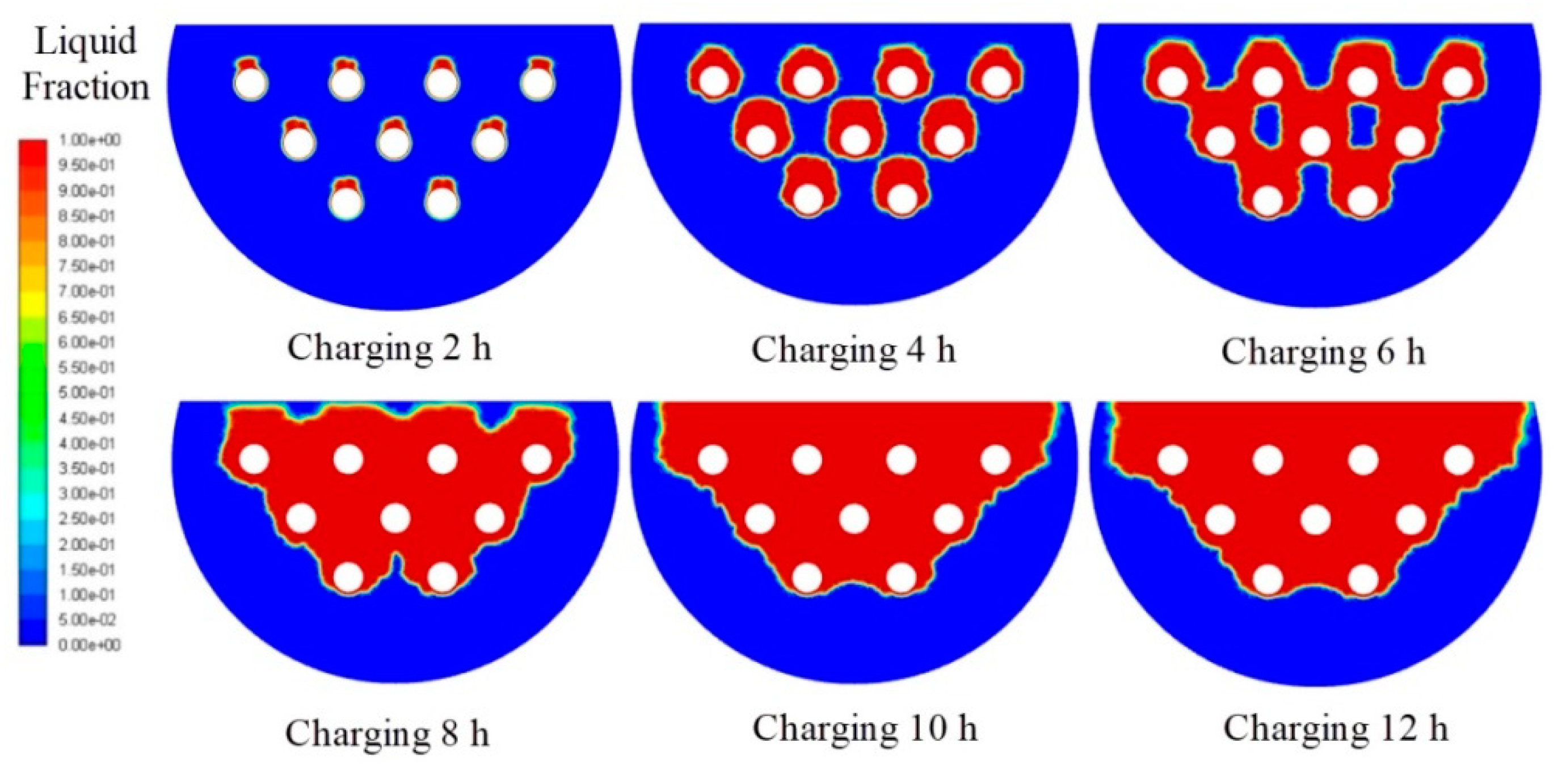
To verify the feasibility of the model, comparisons of the measured and calculated temperatures at different moments are shown in Figure 4. Figure 5 shows the variation of liquid fraction in the process of heat charging. The four small diagrams correspond to the four positions (T1, T2, T3, and T4) of the experimental measurements [19]. The red circular dots and lines show the calculated temperatures at 12 moments. Accordingly, the black square dots and lines show measured temperatures at the same moments. It can be seen that the results obtained from numerical simulation match very well with the measured experimental temperatures. The average departure of temperatures in the four positions shown in Figure 4 is 2.85%, which implies that the simulation model presented in this paper can be used to forecast the melting and solidification process and characteristics of the PCM.

4. Results and Discussion

4.1. Effect of the Tube Bundle Layout for the Shell and Tube Type M-TES Container

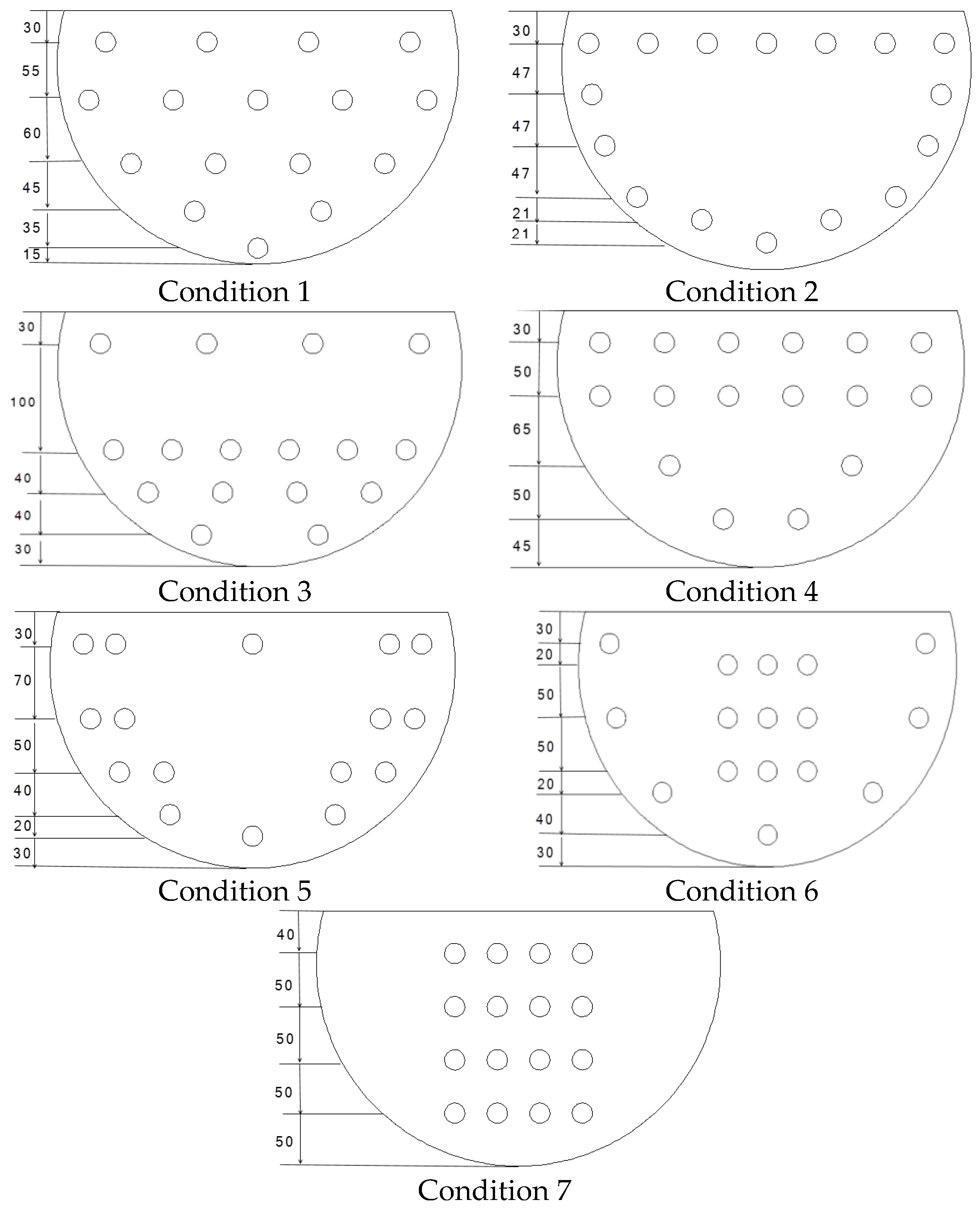
As can be seen in Figure 5, the PCM melts very slowly at the bottom of the container near the wall. The literature [25] gives the same results. The arrangement of the tube bundle in their paper is uniformly arranged, so in this paper, we will try to investigate non-uniform arrangement. The diameter of the tubes in the example calculation is 25 mm, and the number of tubes is 9. The diameter of the tubes is modified to 19 mm, and the number of tubes is modified to 16, while the mass flow rate of the heat exchange medium is guaranteed to be constant. For these 16 tubes, seven types of layouts are given in this paper. They are named in Table 2 from Condition 1 to Condition 7. Their specific distributions can be seen in Figure 6.
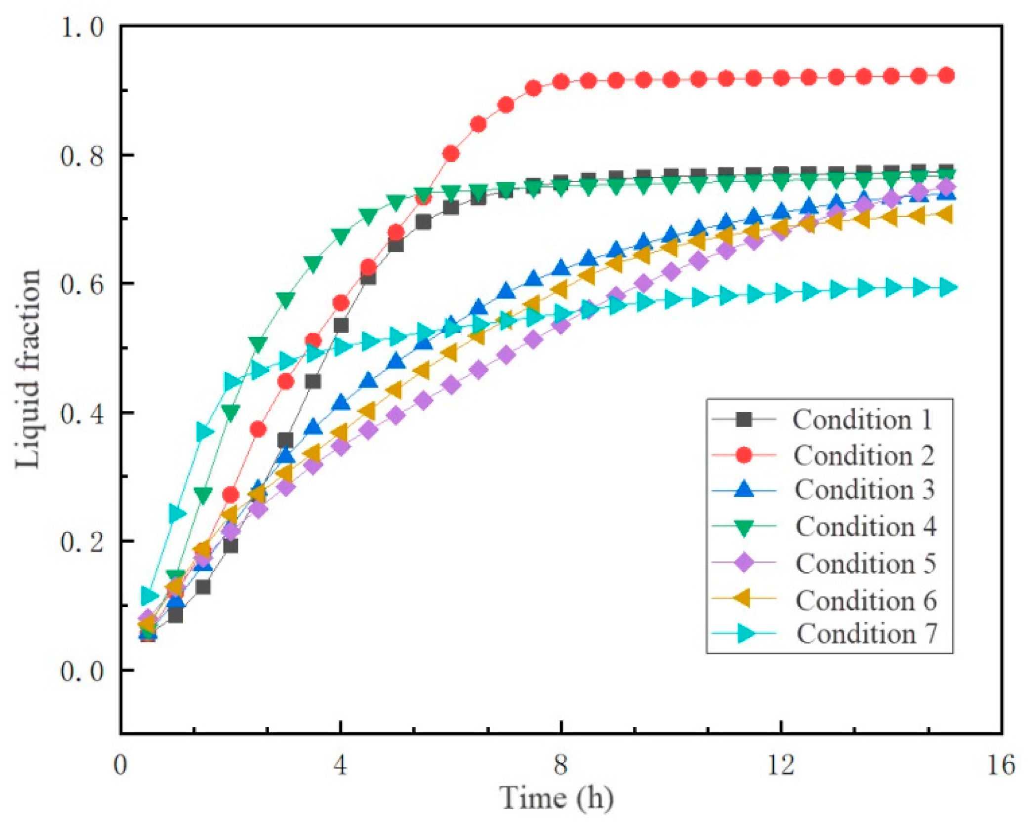
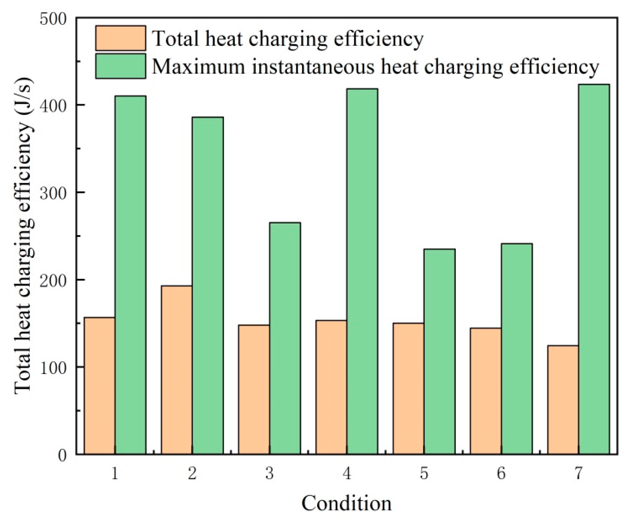
Figure 7 shows the liquid fraction curves for the seven conditions; it can be seen that the heat transfer efficiency of Condition 2 is the best, compared with Condition 1 as the reference standard, when the heat transfer tubes are peripherally distributed. It is calculated that the heat charging efficiency can be increased by 16.2% in the same time. This is due to the fact that when the heat exchanger tubes are distributed around the heat exchanger, it is more conducive to the melting of the PCM around the heat exchanger, thus better enhancing the heat transfer of the heat exchanger. In addition, we can see that in the 0–5th hour of heat storage, the heat charging efficiency of Condition 4 is the highest, but after 5 h, its heat charging efficiency remains basically constant, and the overall efficiency is lower than that of Condition 1. In the rest of the conditions, we found that Condition 7, in which the heat exchanger tubes are concentrated in the center of the M-TES container, is the most unfavorable to heat transfer. Figure 7 also shows that the heat transfer efficiency in this condition is the lowest, especially in the time period after three hours of heat charging, basically no longer carrying out the melting of the phase change material. Looking at the curves of Condition 3, Condition 5, and Condition 6, the heat charging performances of these three conditions are not the worst, but they are only a little better than Condition 1. By calculating the total energy absorbed by the PCM in the shell and tube M-TES container with a thickness of 1 m and combining it with the obtained liquid fraction, the total heat charging efficiency and the instantaneous maximum heat charging efficiency can be given for seven operating conditions. Figure 8 illustrates the comparison of the heat charging efficiencies of 7 conditions. Compared with the other conditions, the transient maximum heat charging efficiency for Condition 2 is not bad, and the total heat charging efficiency is the highest. It can be said that Condition 2 makes full use of natural convection to enhance heat transfer. Therefore, it can be seen from the results that the design with uniform tube arrangement along the wall of the container can achieve the maximum liquid fraction, but the heat charging efficiency is not the fastest, and the heat transfer tubes need to be placed in the center of the carrier as well. The natural convection is fully utilized to strengthen the convective heat transfer, so that as many phase change materials as possible can complete the phase change process. Only in this way can we achieve the maximum energy loading of the M-TES container for each vehicle.

4.2. Effect of Adding Fins for the Shell and Tube Type M-TES Containers

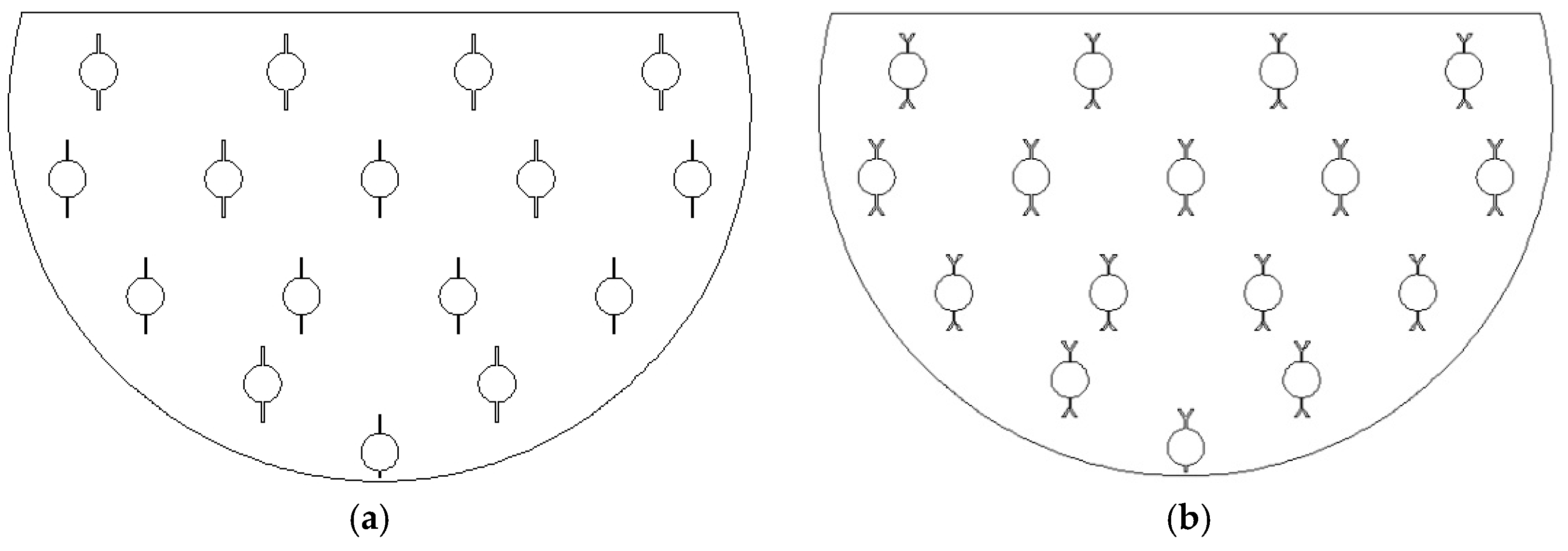
Guo et al. [25] investigated the effect of the number of straight fins on the heat charging and discharging efficiency. Higher heat transfer efficiency can be achieved by adding four straight fins on each heat exchanger tube. Currently, Y-shaped fins are a better form of fins with better heat transfer efficiency than straight and T-shaped fins [30,31]. Therefore, the heat exchanger tube layout of Condition 1 in Figure 6 is applied in this paper. Two vertical straight fins or Y-fins are installed on each heat exchanger tube to compare and study the heat transfer efficiency of the two types of fins. Then, two horizontal or vertical Y-fins are installed on each heat exchanger tube to compare the difference between the two placement methods. Firstly, we introduce the material properties of the Y-shaped fins used in our work. The material of these fins is aluminum. The density is 2719 kg/m3; the specific heat at constant pressure is 871 J/kg·K; and the thermal conductivity is 202.4 W/m·K. The diameter of the 16 heat exchanger tubes in the M-TES container is 19 mm. The detailed parameters of the Y-shaped fins are shown in Table 3 below. Secondly, the installation of the two kinds of fins are shown in Figure 9. Vertical straight fins are installed at the top and bottom of each heat exchanger tube as seen in Figure 9a. Using the same mounting method Figure 9b shows the Y-shaped fin installation. With the same installation, Figure 9b shows the Y-shaped fin placement.
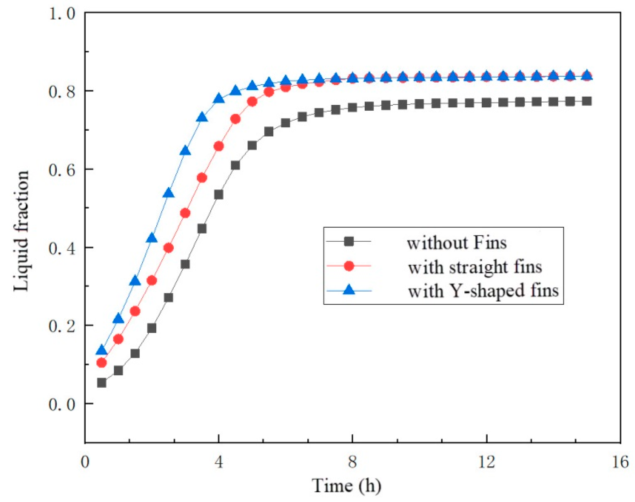
Figure 10 shows the variation of the liquid fraction with time in the M-TES container with fins installed (straight and Y-shaped fins) and without fins installed. As can be seen from the figure, at the beginning of 6 h, the heat charging efficiency of the container with fins installed is greater than the condition without fins installed. The liquid fractions of the container with Y-shaped fins and straight fins gradually tend to be constant during the next 10 h. In general, the heat charging efficiency of the container with Y-shaped fins is stronger than that of the straight fins. In comparison with the container without fins, the heat charging efficiency of the container with Y-shaped fins can be increased by 8.3%. The calculation of the thermal charging efficiency for the different rib structures is based on the 15 h in Figure 10.
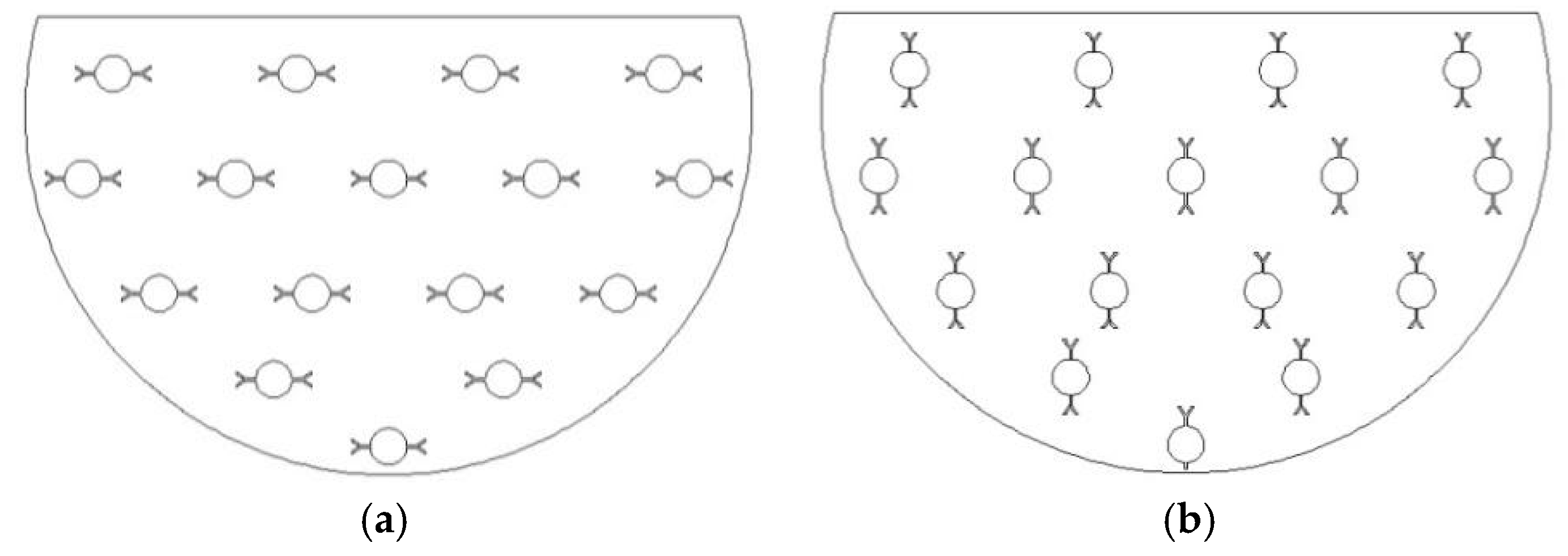
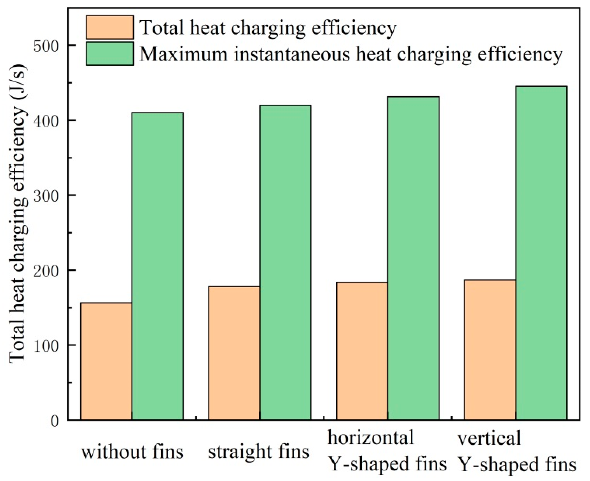
From the previous analysis, the M-TES container with Y-shaped fins installed is more effective. Does the horizontal installation and vertical installation of the Y-shaped fins have any effect on the efficiency of heat charging? With this question, we constructed physical models of horizontally and vertically installed Y-shaped fins and performed computational analysis. Figure 11 illustrates the installation of the horizontal and vertical Y-shaped fins. Figure 12 shows the variation of the liquid fraction with time in the M-TES container with vertical Y-shaped fins and horizontal Y-shaped fins. Figure 13 illustrates the comparison of the heat charging efficiencies of different fin structures. From Figure 12, it can be seen that in the 0–6th hours of thermal storage, the container with Y-shaped fins installed vertically has a stronger heating efficiency than the container with Y-shaped fins installed horizontally. The former was calculated to be 5.91% more efficient than the latter in charging heat during this period. The liquid fraction curves of the two installations almost coincide after 6 h of charging, but the former is still more efficient than the latter placed horizontally. Therefore, in engineering practice, the vertical installation of Y-shaped fins is preferred to improve the heat charging efficiency of the M-TES container.

5. Conclusions

The current demand for energy is increasing, but supplying energy to meet the demand is difficult, and the process of energy generation takes some time, and some of the energy cannot be provided directly to the demand side, so a device that can both collect and carry energy is needed to accomplish this task. In response to the above problems, the mobile thermal energy storage system is a technology that integrates waste heat recovery and thermal energy utilization. The core device of the M-TES system is the phase change heat storage device, the heat transfer performance of which directly affects the whole waste heat utilization efficiency. The shell and tube container, where the internal heat transfer tube bundles are uniformly distributed inside the container, was investigated by some researchers. In addition, the effect of the number of fins on the charging and discharging efficiency was also studied. However, few scholars have considered changing the tube bundle layout of the heat exchanger bundle or changing the shape and installation of the fins. Therefore, this paper investigates indirect-contact M-TES containers with different tube bundle layouts and fin structures by means of numerical simulation. The following conclusions can be drawn:
(1) The peripheral distribution layout of the heat exchanger tube is not the fastest in terms of heat charging, but it can achieve the maximum overall liquid fraction. This layout mode improves the efficiency of heat charging by 12.6% compared with the traditional uniform layout.
(2) The installation of fins on the heat exchanger pipe improves the heat charging efficiency, and the vertical installation of Y-shaped fins achieves better results than the same form of straight fins. Y-shaped fins can improve the heat charging efficiency by 8.3%.
(3) The vertical installation of Y-shaped fins was calculated to be 5.91% more efficient than the horizontal installation of Y-shaped fins in the process of heat charging. The vertical installation of Y-shaped fins is preferred to improve the heat charging efficiency of the M-TES container.

Author Contributions

Conceptualization, Z.K.; methodology, W.Z. and B.Z.; software, K.Q. and C.W.; validation, K.Q., C.W. and Z.Q.; formal analysis, W.Z.; investigation, W.Z. and C.W.; resources, Z.K. and Q.Y.; data curation, Z.K. and Z.Q.; writing—original draft preparation, Z.K., Q.Y. and W.Z.; writing—review and editing, Z.K. and W.Z.; visualization, Z.K. and K.Q.; supervision, Z.K.; project administration, Q.Y.; funding acquisition, Q.Y. All authors have read and agreed to the published version of the manuscript.

Funding

This research was funded by the high-level talents start-up project of North China University of Water Resources and Electric Power (No. 40601).

Conflicts of Interest

The authors declare no conflict of interest. The funders had no role in the design of the study; in the collection, analyses, or interpretation of data; in the writing of the manuscript, or in the decision to publish the results.

References

  1. Niknam, P.H.; Sciacovelli, A. Hybrid PCM-steam thermal energy storage for industrial processes—Link between thermal phenomena and techno-economic performance through dynamic modelling. Appl. Energy 2023, 331, 120358. [Google Scholar] [CrossRef]
  2. Fujita, Y.; Shikata, I.; Kawai, A.; Kamano, H. Latent heat storage and transportation system “TransHeat Container”. In Proceedings of the IEA/ECES Annex 18, the First workshop and Expert Meeting, Tokyo, Japan, 13–15 November 2006. [Google Scholar]
  3. Du, K.; Calautit, J.; Eames, P.; Wu, Y. A state-of-the-art review of the application of phase change materials (PCM) in Mobilized-Thermal Energy Storage (M-TES) for recovering low-temperature industrial waste heat (IWH) for distributed heat supply. Renew. Energy 2021, 168, 1040–1057. [Google Scholar] [CrossRef]
  4. Guo, S.; Liu, Q.; Zhao, J.; Jin, G.; Wu, W.; Yan, J.; Li, H.; Jin, H. Mobilized thermal energy storage: Materials, containers and economic evaluation. Energy Convers. Manag. 2018, 177, 315–329. [Google Scholar] [CrossRef]
  5. Mehling, H.; Cabeza, L.F. Heat and Cold Storage with PCM; Heat and Mass Transfer; Springer: Berlin/Heidelberg, Germany, 2008; pp. 11–55. [Google Scholar]
  6. Horibe, A.; Jang, H.; Haruki, N.; Sano, Y.; Kanbara, H.; Takahashi, K. Melting and solidification heat transfer characteristics of phase change material in a latent heat storage vessel: Effect of perforated partition plate. Int. J. Heat Mass Transf. 2015, 82, 259–266. [Google Scholar] [CrossRef]
  7. Kaizawa, A.; Kamano, H.; Kawai, A.; Jozuka, T.; Senda, T.; Maruoka, N.; Okinaka, N.; Akiyama, T. Technical feasibility study of waste heat transportation system using phase change material from industry to city. ISIJ Int. 2008, 48, 540–548. [Google Scholar] [CrossRef] [Green Version]
  8. Guo, S.; Zhao, J.; Wang, W.; Jin, G.; Wang, X.; An, Q.; Gao, W. Experimental study on solving the blocking for the direct contact mobilized thermal energy storage container. Appl. Therm. Eng. 2015, 78, 556–564. [Google Scholar] [CrossRef]
  9. Anandan, S.S.; Sundarababu, J. A comprehensive review on mobilized thermal energy storage. Energy Sources Part A Recovery Util. Environ. Eff. 2021, 1–24. [Google Scholar] [CrossRef]
  10. Peiró, G.; Gasia, J.; Miró, L.; Cabeza, L.F. Experimental evaluation at pilot plant scale of multiple PCMs (cascaded) vs. single PCM configuration for thermal energy storage. Renew. Energy 2015, 83, 729–736. [Google Scholar] [CrossRef] [Green Version]
  11. Höhlein, S.; König-Haagen, A.; Brüggemann, D. Thermophysical characterization of MgCl2· 6H2O, xylitol and erythritol as phase change materials (PCM) for latent heat thermal energy storage (LHTES). Materials 2017, 10, 444. [Google Scholar] [CrossRef] [Green Version]
  12. Diarce, G.; Gandarias, I.; Campos-Celador, A.; García-Romero, A.; Griesser, U. Eutectic mixtures of sugar alcohols for thermal energy storage in the 50–90 C temperature range. Sol. Energy Mater. Sol. Cells 2015, 134, 215–226. [Google Scholar] [CrossRef]
  13. Yang, X.; Lu, Z.; Bai, Q.; Zhang, Q.; Jin, L.; Yan, J. Thermal performance of a shell-and-tube latent heat thermal energy storage unit: Role of annular fins. Appl. Energy 2017, 202, 558–570. [Google Scholar] [CrossRef]
  14. Nagano, K.; Ogawa, K.; Mochida, T.; Hayashi, K.; Ogoshi, H. Thermal characteristics of magnesium nitrate hexahydrate and magnesium chloride hexahydrate mixture as a phase change material for effective utilization of urban waste heat. Appl. Therm. Eng. 2004, 24, 221–232. [Google Scholar] [CrossRef]
  15. Nomura, T.; Okinaka, N.; Akiyama, T. Waste heat transportation system, using phase change material (PCM) from steelworks to chemical plant. Resour. Conserv. Recycl. 2010, 54, 1000–1006. [Google Scholar] [CrossRef]
  16. Kumar, Y.A.; Kim, H.-J. Effect of time on a hierarchical corn skeleton-like composite of coo@ zno as capacitive electrode material for high specific performance supercapacitors. Energies 2018, 11, 3285. [Google Scholar] [CrossRef] [Green Version]
  17. Moniruzzaman, M.; Anil Kumar, Y.; Pallavolu, M.R.; Arbi, H.M.; Alzahmi, S.; Obaidat, I.M. Two-dimensional core-shell structure of cobalt-doped@ MnO2 nanosheets grown on nickel foam as a binder-free battery-type electrode for supercapacitor application. Nanomaterials 2022, 12, 3187. [Google Scholar] [CrossRef] [PubMed]
  18. Kaizawa, A.; Kamano, H.; Kawai, A.; Jozuka, T.; Senda, T.; Maruoka, N.; Akiyama, T. Thermal and flow behaviors in heat transportation container using phase change material. Energy Convers. Manag. 2008, 49, 698–706. [Google Scholar] [CrossRef]
  19. Wang, W.; Guo, S.; Li, H.; Yan, J.; Zhao, J.; Li, X.; Ding, J. Experimental study on the direct/indirect contact energy storage container in mobilized thermal energy system (M-TES). Appl. Energy 2014, 119, 181–189. [Google Scholar] [CrossRef]
  20. Wang, W.; Li, H.; Guo, S.; He, S.; Ding, J.; Yan, J.; Yang, J. Numerical simulation study on discharging process of the direct-contact phase change energy storage system. Appl. Energy 2015, 150, 61–68. [Google Scholar] [CrossRef]
  21. Li, H.; Wang, W.; Yan, J.; Dahlquist, E. Economic assessment of the mobilized thermal energy storage (M-TES) system for distributed heat supply. Appl. Energy 2013, 104, 178–186. [Google Scholar] [CrossRef]
  22. Agyenim, F.; Eames, P.; Smyth, M. Heat transfer enhancement in medium temperature thermal energy storage system using a multitube heat transfer array. Renew. Energy 2010, 35, 198–207. [Google Scholar] [CrossRef]
  23. Al-Mudhafar, A.H.; Nowakowski, A.F.; Nicolleau, F.C. Performance enhancement of PCM latent heat thermal energy storage system utilizing a modified webbed tube heat exchanger. Energy Rep. 2020, 6, 76–85. [Google Scholar] [CrossRef]
  24. Wang, Y.; Yu, K.; Ling, X. Experimental study on thermal performance of a mobilized thermal energy storage system: A case study of hydrated salt latent heat storage. Energy Build. 2020, 210, 109744. [Google Scholar] [CrossRef]
  25. Guo, S.; Zhao, J.; Wang, W.; Yan, J.; Jin, G.; Zhang, Z.; Gu, J.; Niu, Y. Numerical study of the improvement of an indirect contact mobilized thermal energy storage container. Appl. Energy 2016, 161, 476–486. [Google Scholar] [CrossRef]
  26. Zhang, C.; Li, J.; Chen, Y. Improving the energy discharging performance of a latent heat storage (LHS) unit using fractal-tree-shaped fins. Appl. Energy 2020, 259, 114102. [Google Scholar] [CrossRef]
  27. Parsazadeh, M.; Duan, X. Numerical study on the effects of fins and nanoparticles in a shell and tube phase change thermal energy storage unit. Appl. Energy 2018, 216, 142–156. [Google Scholar] [CrossRef]
  28. Brent, A.; Voller, V.R.; Reid, K. Enthalpy-porosity technique for modeling convection-diffusion phase change: Application to the melting of a pure metal. Numer. Heat Transf. Part A Appl. 1988, 13, 297–318. [Google Scholar]
  29. Kakiuchi, H. A study of erythritol as phase change material. In Proceedings of the IEA Annex 10-PCMs and Chemical Reactions for Thermal Energy Storage 2nd Workshop, Sofia, Bulgaria, 11–13 April 1998. [Google Scholar]
  30. Lorenzini, G.; Moretti, S. Numerical heat transfer optimization in modular systems of Y-shaped fins. J. Heat Transf. 2008, 130, 081801. [Google Scholar] [CrossRef]
  31. Lorenzini, G.; Moretti, S. Numerical analysis on heat removal from Y-shaped fins: Efficiency and volume occupied for a new approach to performance optimisation. Int. J. Therm. Sci. 2007, 46, 573–579. [Google Scholar] [CrossRef]
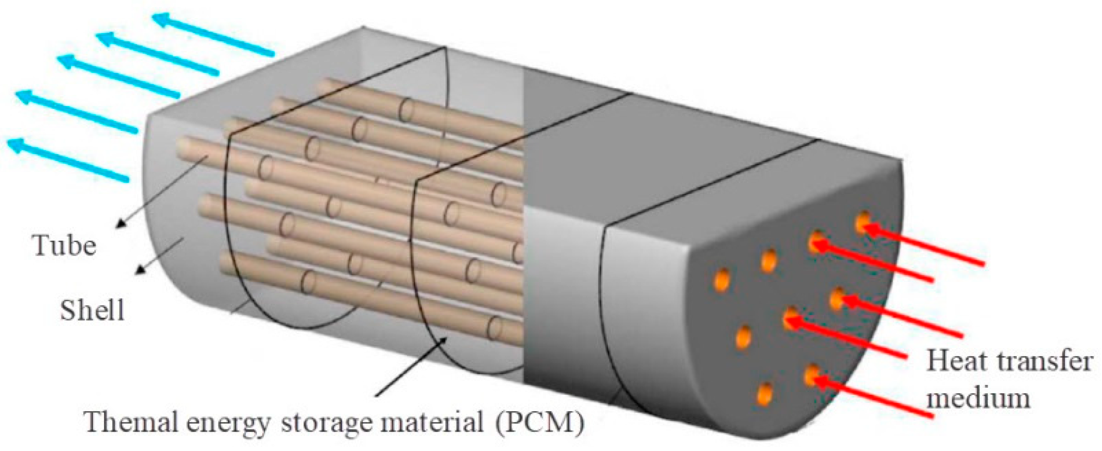
Figure 1. Schematic diagram of a typical shell and tube type M-TES container [20].
Sustainability 15 05511 g001
Figure 2. 2D physical model of the shell and tube type M-TES container.
Sustainability 15 05511 g002
Figure 3. Meshes for the 2D simulation model.
Sustainability 15 05511 g003
Figure 4. Comparison of the measured and calculated temperatures at 12 moments and 4 positions.
Sustainability 15 05511 g004
Figure 5. Variation of liquid fraction in the process of heat charging.
Sustainability 15 05511 g005
Figure 6. Physical models of the seven working conditions (The units of numbers are mm).
Sustainability 15 05511 g006
Figure 7. The liquid fraction of the 7 conditions.
Sustainability 15 05511 g007
Figure 8. Comparison of the heat charging efficiencies of 7 conditions.
Sustainability 15 05511 g008
Figure 9. Physical model with two types of fins. (a). Vertical straight fins; (b). Vertical Y-shaped fins.
Sustainability 15 05511 g009
Figure 10. Comparison of liquid fractions with and without fins installed.
Sustainability 15 05511 g010
Figure 11. Physical model with two types of Y-shaped fins. (a). Y-shaped fins placed vertically; (b). Y-shaped fins placed horizontally.
Sustainability 15 05511 g011
Figure 12. Comparison of liquid fractions with vertical and horizontal Y-shaped fins.
Sustainability 15 05511 g012
Figure 13. Comparison of the heat charging efficiencies of different fin structures.
Sustainability 15 05511 g013
Table 1. Physical properties of four PCMs.
PropertyErythritol [29]Xylitol [11,12]MCHH [14]Sodium Hydroxide [15]
Latent heat (kJ/kg)340280167164
Melting point (°C)1199311558
Density (kg/m3)1480 (at 20 °C)15151569 (20 °C); 1450 (120 °C)
1300 (at 140 °C) 1422 (128 °C)
Specific heat (kJ/(kg·K))1.38 (at 20 °C)1.33 (solid)2.1 (25 °C); 2.25 (100 °C)2.79 (solid)
2.61 (120 °C)
2.77 (at 140 °C)2.36 (liquid)
Viscosity (kg·m−1·s−1)0.02895 (at 20 °C)
0.01602 (at 140 °C)
Thermal conductivity (W·m−1·K−1)0.732 (at 20 °C)0.52 (solid)0.704 (110 °C)0.7 (solid)
0.125 (at 140 °C)0.36 (liquid)0.570 (120 °C)
Price ($/t)1458–15964352–58021360128
Table 2. Seven heat exchanger tube layout patterns.
NameLayout
Condition 1Uniform distribution
Condition 2Peripheral distribution
Condition 3The upper part is sparse and the lower part is dense
Condition 4The upper part is dense and the lower part is sparse
Condition 5Sparse on both sides and dense in the middle.
Condition 6Dense on both sides and sparse in the middle.
Condition 7Center 4 × 4 distribution
Table 3. Fins types and parameters.
Fin TypeNumber of FinsFin HeightFin Thickness
Straight fins2 × 16101
Y-shaped fins2 × 16101
Disclaimer/Publisher’s Note: The statements, opinions and data contained in all publications are solely those of the individual author(s) and contributor(s) and not of MDPI and/or the editor(s). MDPI and/or the editor(s) disclaim responsibility for any injury to people or property resulting from any ideas, methods, instructions or products referred to in the content.