Article

Support Control Design of Mining Roadway under Goaf of Close-Distance Coal Seam

College of Energy and Mining Engineering, Shandong University of Science and Technology, Qingdao 266590, China
*
Author to whom correspondence should be addressed.
Sustainability 2023, 15(6), 5420; https://doi.org/10.3390/su15065420
Submission received: 1 March 2023 / Revised: 11 March 2023 / Accepted: 16 March 2023 / Published: 18 March 2023
(This article belongs to the Special Issue Sustainability in Geology and Civil Engineering)

Abstract

:
Coal resources have always been the focus of attention in the field of sustainable development. Based on the problem of surrounding rock control in close-distance coal seams, first, a mechanical model of floor failure was established based on the 29204 working face in Dongqu Mine; the failure mechanism of the floor was revealed by the zero displacement line, and a method to judge the occurrence state of the roof in the lower coal seam was put forward. Furthermore, by FLAC3D numerical simulation software, the mechanical model is verified, and the optimal support parameters are optimized, and the optimal water–cement ratio and grouting pressure are determined to be 0.6 and 3 MPa respectively. The application shows that the roof displacement is reduced by about 73.48% compared with the control group. Compared with the control group, the cable stress decreased by about 50.68%, and the application effect is remarkable. The research results provide an effective solution to ensure the sustainable development of coal resources and disaster prevention.

1. Introduction

Close-distance coal seams mean that the distance of two coal seams is very close in coal mining, which will have a great mutual influence on the mining process. Especially for the upper coal floor in close-distance coal seams, the uplift degree of the floor changes significantly due to the influence of factors, such as rock properties, coal seam thickness, and mining disturbance. The different uplift degree of the floor is of great significance to the stability of the surrounding rock of mining roadways under a goaf of close coal seams. The traditional support methods, such as single pillar and pipe roofs have many problems, such as the high personnel demand, high labor intensity, and low support efficiency, which restrict the control effect seriously of the roadway and the high yield and high efficiency of coal [1,2]. Therefore, the support control design is essential for ensuring the control effect of mining roadways and realizing the sustainable development of geotechnical engineering.
In close-distance coal, failure depth has a significant impact. Excessive damage depth will lead to serious damage to mining roadways under a goaf and even lead to disasters such as overall instability [3,4,5]. Since the early 20th century, scholars have performed many research studies on the failure characteristics of floors. In terms of theoretical models, Li et al. [6,7] used plastic mechanics to determine the plastic failure range of a floor in a coal seam at close distances. The mechanical model of floor failure was developed by Liang et al. [8,9] using limit equilibrium theory and verified the accuracy of the model by combining numerical simulation and field monitoring results. In addition, considering the different load forms, Cheng et al. [10,11] established the mechanical model of floors under different loads, which provided a basis for roadway support design, considering the structural form of the floor, using a mechanical model. Sun et al. [12,13,14] determined what mechanical conditions must be met for the floor to remain stable. Some scholars have studied the influencing factors of floor failure and made some achievements [15].
In terms of numerical simulation and physical similarity simulation experiments, based on elasticity theory, Wang et al. [16,17,18] revealed the failure mechanism of the floor by establishing a mechanical model and verifying it by field engineering. The strain softening model was used by Yin et al. [19] to study the failure state of the floor, and they obtained the analytical expression for plastic mechanics. Considering the characteristics of coal and rock, Ma et al. [20] obtained the progressive failure law of floors by the RFPA numerical simulation method. Some scholars have also analyzed it from the microscopic point of view and obtained the mechanical analytical formula of floor failure [21].
In the field practice, based on the stress-strain technology of boreholes, Guo et al. [22,23] obtained the omni-directional floor disturbance failure law, which provided a method for predicting the floor failure depth, based on self-developed equipment. An inclined coal seam floor failure characteristic was determined by Meng et al. [24] and put forward the corresponding control design method. Furthermore, through field practice, Ning et al. [25] obtained the actual failure situation and crack evolution characteristics of floors, which provides real data for the study of floor failure mechanisms. Some scholars use optical fiber sensors to measure the failure depth of the bottom plate [26,27,28].
Researchers have carried out extensive research on the failure characteristics of floors at home and abroad. However, in close-distance coal seams, there are still some deficiencies around the failure mechanism and the supporting design method suitable for it. To establish a suitable supporting design method for lower coal mining roadway by revealing the failure mechanism of floors in close-distance coal seams, the workface of 29204 being mined in Dongqu Mine, is used as a background to illustrate how upper coal floor failure occurs and puts forward a method for judging the integrity of the lower coal roof. On this basis, combined with FLAC3D numerical simulation software, the design method of supporting parameters for mining roadway in 29204 working face is determined and verified by field cases. The results provide a reference for revealing the failure mechanism and disaster prevention of close-range coal seams.

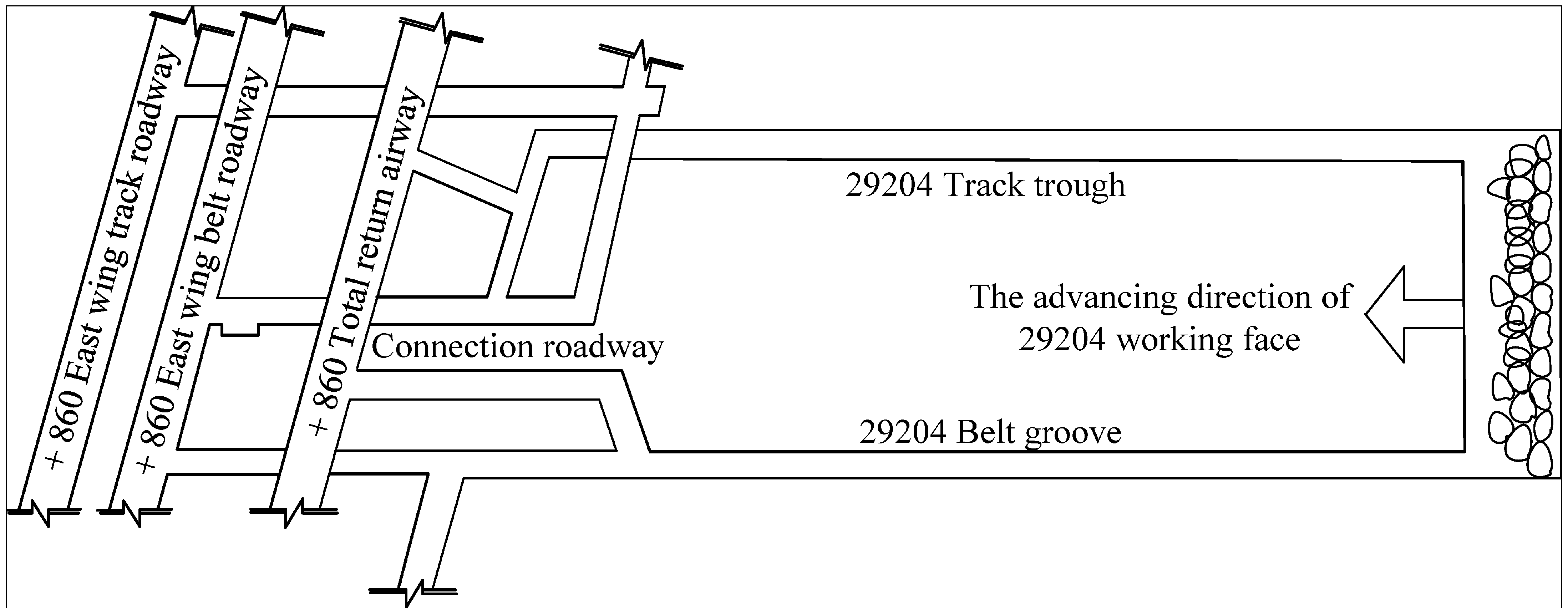
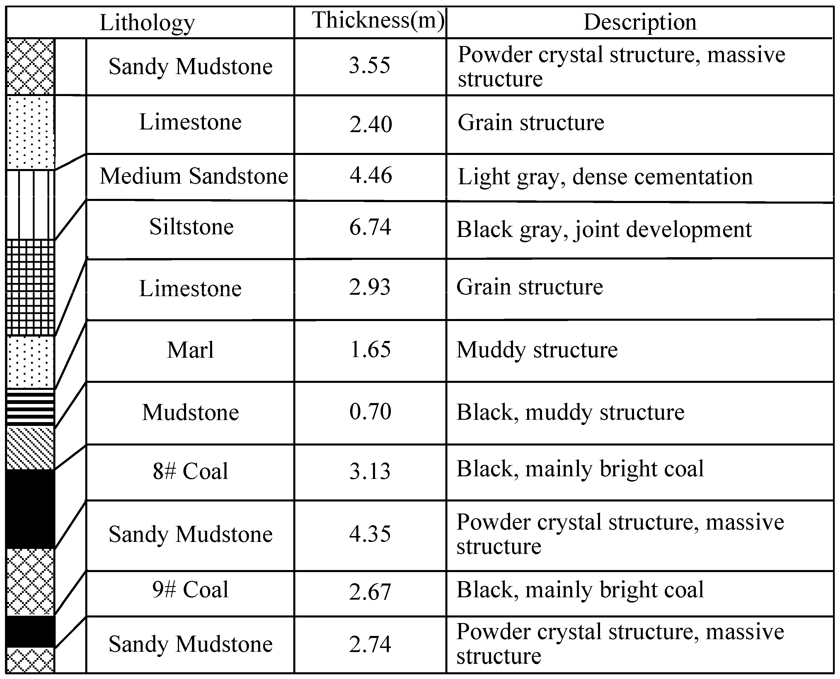
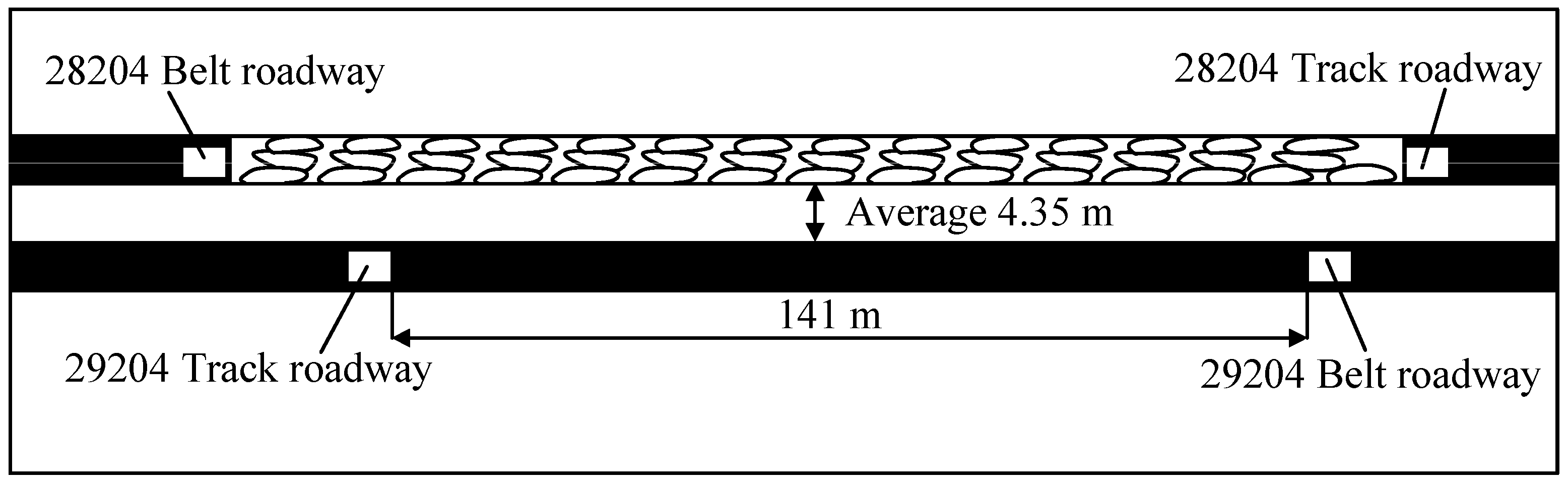
2. Engineering Background

Dongqu Mine is on the south bank of Fenhe River in Taiyuan City, Shanxi Province, and belongs to Xishan Coal and Electricity Co., Ltd. 29204 working face is located at 270 m from buried depth, the advancing length is 1335 m, the length of the working face is about 1171 m, and the mining area is about 165,111 m2. The inclined length of working face is 141 m, the footage is 4.8 m every day, and the roof is managed by the full caving method. The dip angle of the coal seam is 0°~5°, which belongs to a nearly horizontal coal seam. Figure 1 shows the roadway layout plan for the 29204 working face.
The 28204 working face belongs to the coal seam 8# and has been mined, and the 29204 working face belongs to the 9# coal seam below the 8# coal seam. Among them, the layer spacing of 8# and 9# coal is about 4.35 m, that is, there is the close distance coal seam. The comprehensive histogram of the roof and floor is shown in Figure 2, and the relationship between 8# and 9# coal seams is shown in Figure 3.

3. Failure Mechanism and Integrity Discrimination of Close Distance Coal Seam Floor

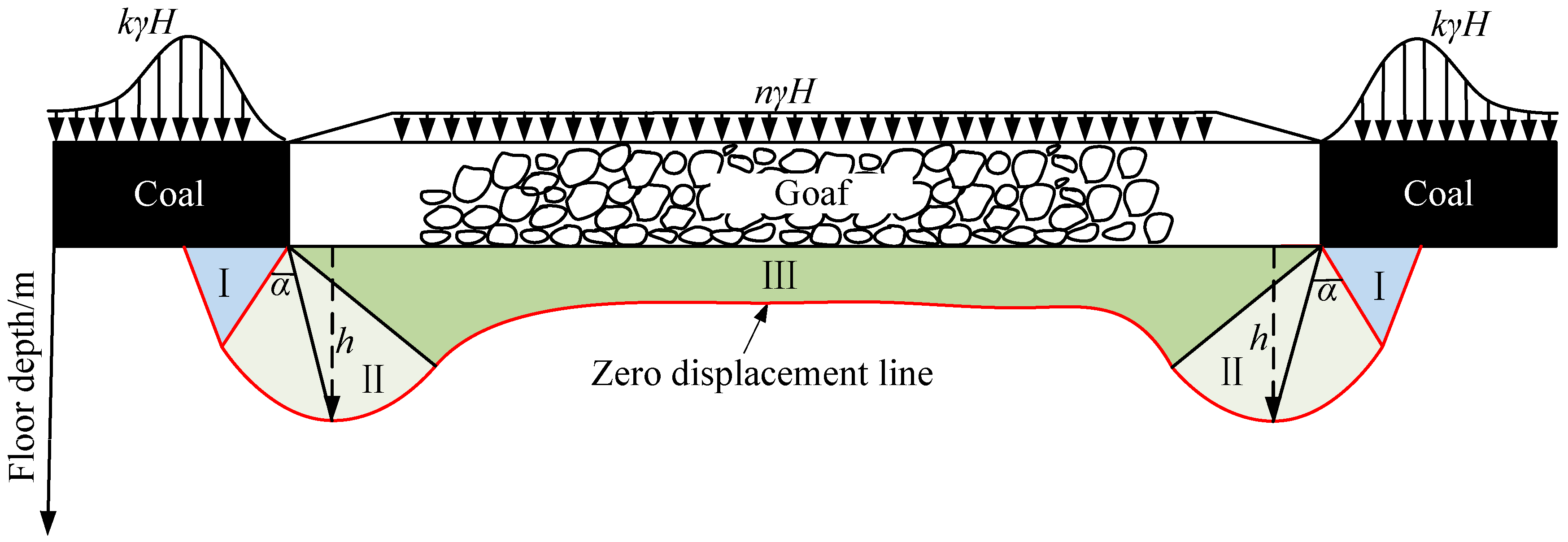
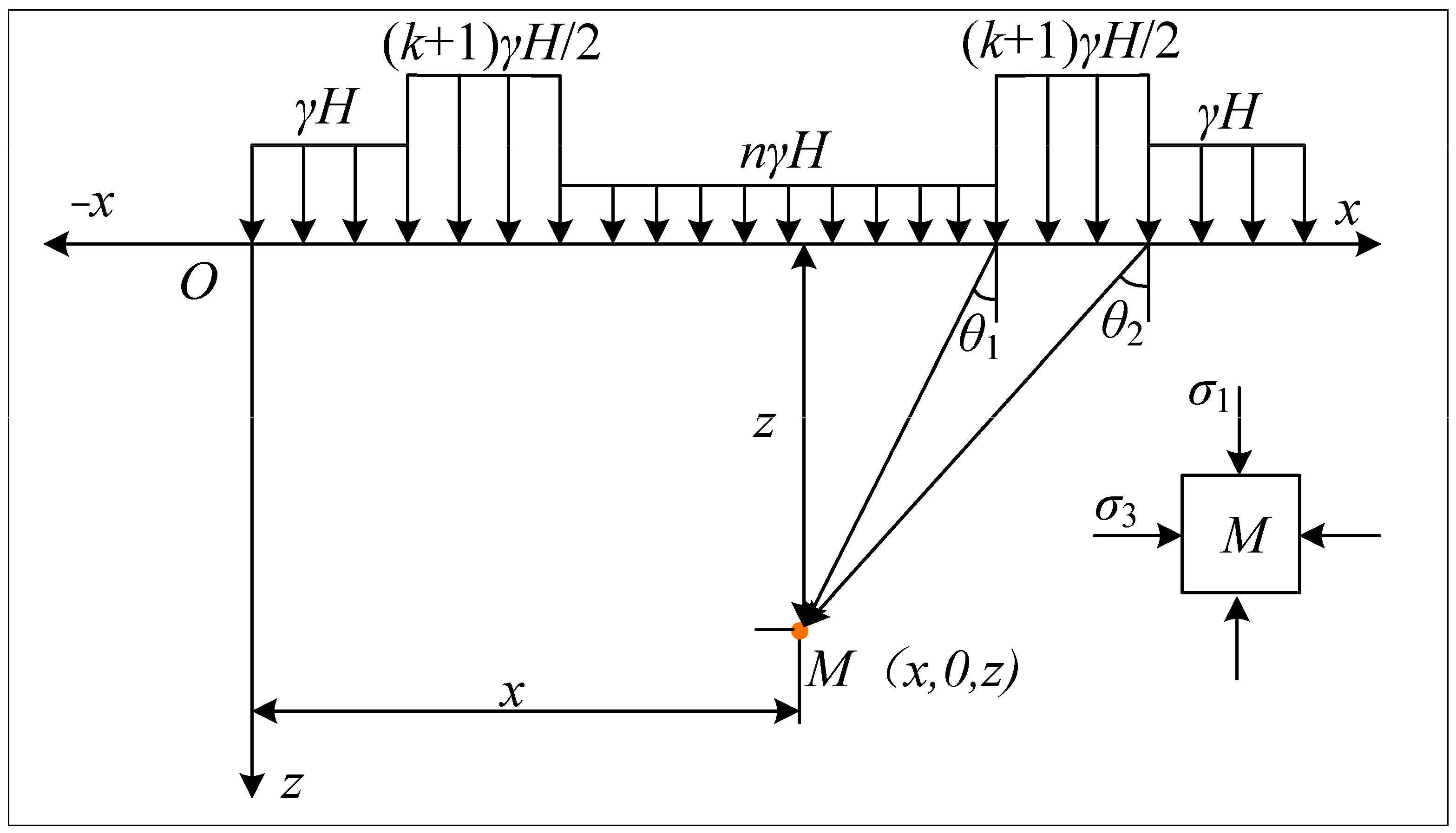
3.1. Failure Mechanism of upper Coal Seam Floor

When mining is being carried out, the plastic failure of the strata between coal layers will occur in a certain range. According to Karl Terzaghi’s theory [29], when the bearing strength of rock mass exceeds its yield strength in a certain range, the plastic zone produced by the failure of the floor within the load range will be connected together. Based on this, this paper holds that there must be a displacement zero point in the process of plastic failure and deformation caused by upper coal seam mining, that is, the displacement of the strata at this point is zero. At this time, a line with zero displacement can be obtained by connecting the points with zero displacement in the interlayer strata, and it is defined as a ‘zero displacement line’. Compression or expansion of strata above the zero displacement line will occur during the mining of the working face. In order to determine whether coal seam mining will affect upper coal seam mining, the zero displacement line will be crucial.
Based on the above analysis, a mechanical model of coal seam mining in close coal seams is presented in Figure 4.
Three areas of the floor can be divided by the zero displacement line, namely compression area I, expansion area II, and compaction area III. Among them, area II is squeezed by the expansion of rock mass in areas I and III in the horizontal direction, and because there is free space above this area (formed after roadway excavation), the rock mass in this area will move to the upper free space (roadway direction) under the constraint of horizontal stress on both sides, resulting in floor heave. It can be seen that this area is the action area that produces significant pressure relief and release to the lower coal seam and interlayer rock mass.
The stress distribution in Figure 4 is simplified in Figure 5 to calculate the failure depth of the floor theoretically.
Based on the above analysis, the lower coal and interlayer rock mass are affected due to the expansion zone above the zero displacement line; by solving the maximum failure depth in this area, the influenced degree of the lower coal mining can be judged. Saint Venant’s principle can simplify the calculation, taking the equivalent stress value of advanced abutment pressure as (k + 1)γH/2. At the same time, the theory of elasticity and the principle of stress superposition are used, and the stress analytical formula of any point (micro-element) M in the floor strata after mining under the loading can be obtained as follows:
σ z   =   k + 1 2 π γ H ( sin θ 2 cos θ 2 sin θ 1 cos θ 1 + θ 2 θ 1 ) σ x = k + 1 2 π γ H [ θ 2 θ 1 sin ( θ 2 θ 1 ) cos ( θ 2 + θ 1 ) ] τ z x   =   k + 1 2 π γ H ( sin 2 θ 2 sin 2 θ 1 )
In the equation, k is the coefficient of stress concentration; γ is the gravity density, N/m3; H is the depth of coal, m; θ1 and θ2 are the angles of any point M of the floor, °.
The principal stress calculation equation of micro element can be expressed according to the material mechanics
σ 1   =   σ z + σ x 2 + σ z σ x 2 2 + τ z x 2 σ 3   =   σ z + σ x 2 σ z σ x 2 2 + τ z x 2
Substitute Equation (2) into Equation (1):
σ 1   =   k + 1 2 π γ H [ θ 2 θ 1 + sin ( θ 2 θ 1 ) ] σ 3   =   k + 1 2 π γ H [ θ 2 θ 1 sin ( θ 2 θ 1 ) ]
Considering the self-weight stress of the rock in the floor and the compaction effect of goaf formed after mining, the self-weight stress q1 and the load q2 after goaf compaction are taken as:
q 1   =   γ z q 2   =   n γ H
where z is the depth of any point M, m; n is the pressure reduction coefficient of goaf.
Combined with Equations (3) and (4), the principal stress of any point M is:
σ 1   =   k + 1 2 π γ H [ θ 2 θ 1 + sin ( θ 2 θ 1 ) ] + γ z + n γ H σ 3   =   k + 1 2 π γ H [ θ 2 θ 1 sin ( θ 2 θ 1 ) ] + γ z + n γ H
To simplify the above equation, set the
α   =   θ 2 θ 1
So
σ 1   =   k + 1 2 π γ H [ α + sin ( α ) ] + γ z + n γ H σ 3   =   k + 1 2 π γ H [ α sin ( α ) ] + γ z + n γ H
After mining, the above equation expresses the principal stress at any point in the strata. When the M point gradually changes from elastic deformation to plastic deformation, according to the yield criterion based on Mohr-Coulomb, there are
1 2 ( σ 1 σ 3 )   =   c cos φ + 1 2 ( σ 1 + σ 3 ) sin φ
Substitute Equation (7) into Equation (8) is available
z   =   H [ k + 1 2 π sin α α sin φ sin φ n ] c γ tan φ
Combined with Figure 5, there is always
d z d α   =   0
Combining Equations (9) and (10), the maximum failure depth h of region II is
h   =   H ( k + 1 2 π c sin φ α cos φ cos φ n ) c γ tan φ
Substituting the real parameters, the thickness of coal is 3.13 m, the depth of the coal seam is 262 m, the coefficient of stress concentration k is 1.5, the cohesion of floor c is 3.86 MPa, and the internal friction angle φ is 28.4°. By Equation (11), the failure depth of the upper coal is 3.742 m. Obviously, the spacing between coal layers is greater than 3.742 m. It can be seen that there is a partial complete direct roof above the track groove of the 29204 working face.

3.2. Analysis of Occurrence State of Lower Coal Seam Roof

During mining, the yield ratio is calculated between the coal seam spacing and the failure depth of the ground, and if the interlayer rock stress exceeds its yield limit, the fracture of the lower coal seam roof is further expanded, which leads to the change of the roof occurrence state. Therefore, the definition of yield ratio can be used to analyze the occurrence state of roof strata in lower coal seams. When the interlayer spacing between layers of coal is less than 0.5 m, the rock between layers will be destroyed due to the mining of upper coal, which is continuous and extensive. Furthermore, the interlayer spacing of 0.5 m is enough for cracks to expand and penetrate, and compared with the thickness of upper and lower layers of coal, the difference of 0.5 m is larger. At this time, the upper and lower layers of coal can be regarded as one layer, and the rock between layers can be regarded as the Parting. The classification of rock integrity between adjacent coal seams considering yield ratio can be referred to in Table 1.
Combined with Equation (11), the failure depth is 3.742 m, the spacing is 4.35 m, and the safety factor is 2, then f·h is 7.484 m. According to the calculation, the interlayer spacing is a range of 1.5 m to 7.484 m, so it belongs to the condition of block fracture. The lower coal seam roof has a good occurrence state and can achieve good anchoring bearing performance. At the same time, as a result of mining damage to floors and roofs, in order to achieve a good anchoring effect, the anchoring depth should be as large as possible; however, the maximum should not be greater than the coal seam spacing, so as not to make the anchoring of the anchor rod or cable to the goaf, thus making the anchoring invalid.

4. Design of Supporting Parameters of Mining Roadway in 29204 Working Faces

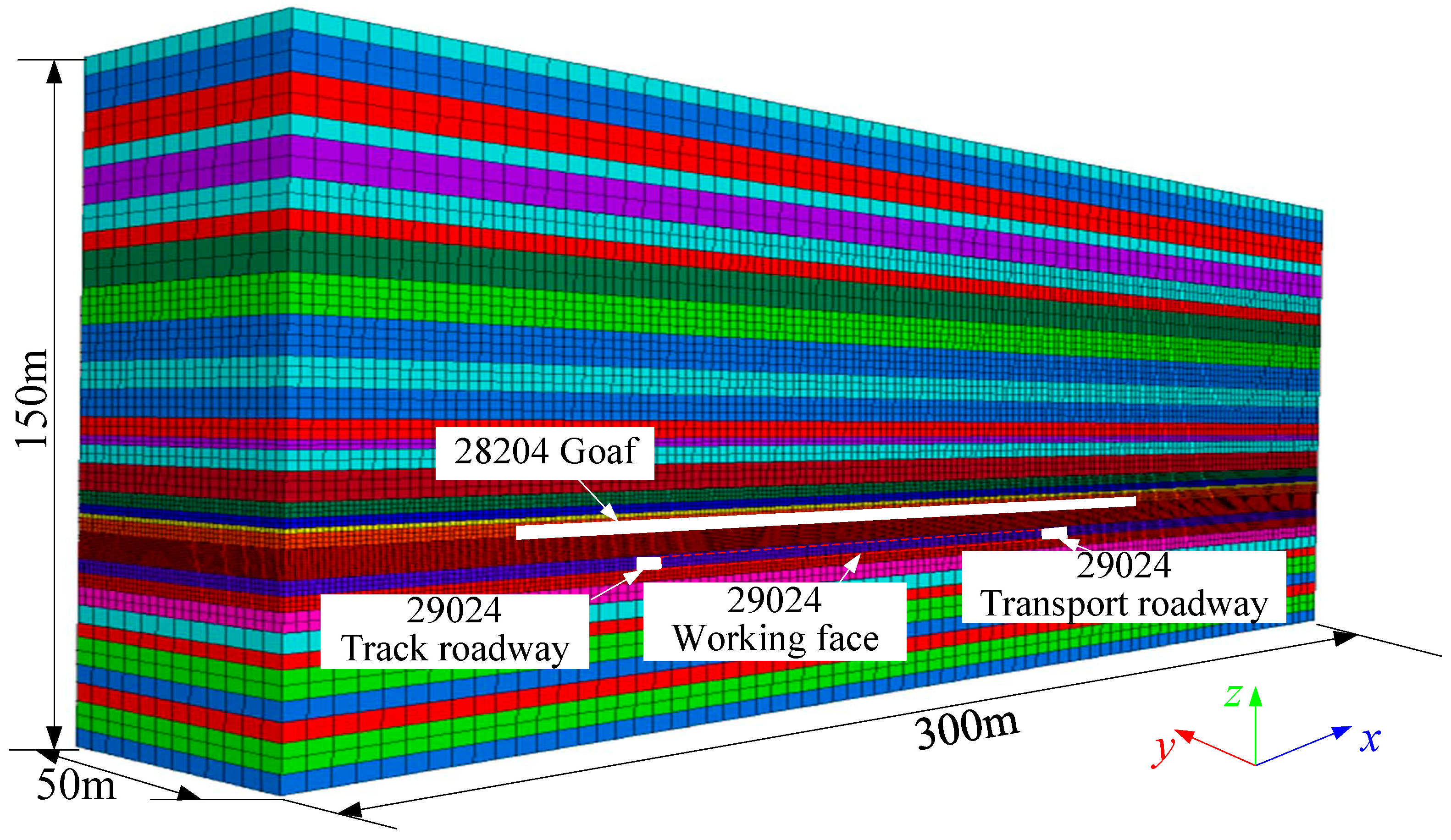
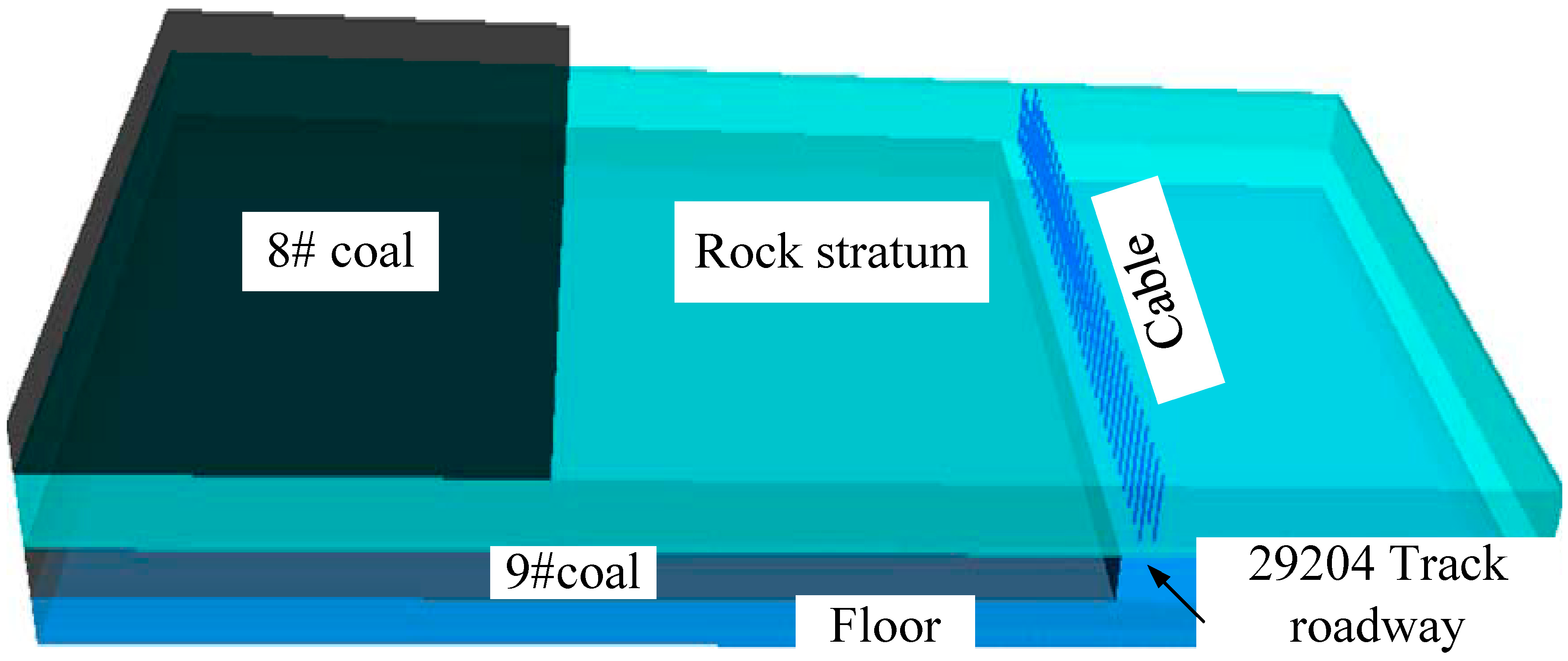
4.1. Numerical Model

Based on the track roadway of 29204, a FLAC3D numerical simulation model is established according to the properties of coal, roof, and floor rocks. Based on the comprehensive histogram (Figure 2), the model is established from bottom to top according to the lithology and thickness of the rock/coal layer. The model is 300 m× 50 m× 150 m. Considering that the buried depth of 9# coal is 270 m and the coal is 109 m away from the top of the model, the vertical load is 4.025 MPa, and it is set at the top of the model. The field measurement shows that the horizontal stress has little effect on the deformation of the surrounding rock of the roadway but is mainly affected by the vertical stress of the roof, so the horizontal stress is not applied in the numerical simulation, and fixed boundaries are imposed in the model boundaries. The specific model diagram is shown in Figure 6.
Based on the actual mine geological data of Dongqu Coal Mine, the basic properties are shown in Table 2.

4.2. Simulation Scheme

Based on the above analysis, it is proposed to use a grouting cable with a length of 4.3 m as the supporting material, and the cable arrangement is shown in Figure 7. Specifically, the grouting anchor cables are set on the roof of the 29204 track along the advancing direction of the working face, with two in each row, and the pre-tightening force is 200 kN. The spacing and row spacing are determined according to the simulation scheme.
At the same time, combined with the relevant supporting parameters of the adjacent working face, it is proposed to determine the range of slurry water–cement ratio is 0.4~0.7, and 0.1 is taken as an interval. Some studies have shown that the different slurry water–cement ratio will lead to the increase of elastic modulus, internal friction angle, cohesion and uniaxial tensile strength of surrounding rock [30,31]. Therefore, in order to make the simulation more convenient, when the water–cement ratio of the slurry decreases by 0.1, the increase of the elastic modulus, cohesion and uniaxial tensile strength of the surrounding rock is considered as 2, 1, and 1 times, respectively, and the internal friction angle is considered as 4°. The scheme is shown in Table 3.
For the grouting pressure, according to the existing literature [32,33], cable grouting pressure and slurry diffusion radius are related. As shown in Figure 8, with the increase of the grouting pressure, the diffusion radius of the slurry shows an increasing trend and the growth rate with the increase of the grouting pressure. Therefore, based on Figure 8, when the grouting pressure is 2, 3, 4, and 5 MPa, the grouting radius is 1.3, 1.5, 1.65, and 1.75 m, respectively. Table 4 shows the simulation scheme.
The simulation follows the principle of controlling variables, and the grouting pressure is controlled at 3 MPa when different water–cement ratios are studied. When studying different grouting pressures, control the water–cement ratio to 0.7. The model adopts the method of step-by-step excavation, that is, the 8# coal is mined first, and the lower coal is mined step by step after the model calculates the balance, and each excavation is 10 m. At the same time, for a better understanding of how the roadway along the track in 29204 working face interacts with surrounding rock control, a spherical section is used to display the variation law of vertical displacement cloud map and stress cloud map, and a group of monitoring points is placed along the middle part of the roadway. Under the influence of the mining in 29204 working face, it is possible to monitor the vertical stress and displacement evolution of the rock surrounding the track roadway, and the evolution of vertical displacement and stress nephogram are analyzed, and the control effect of surrounding rock of roadway under different simulation schemes is obtained by comprehensive comparison, and then the optimal water–cement ratio and grouting pressure are determined.

4.3. Result Analysis

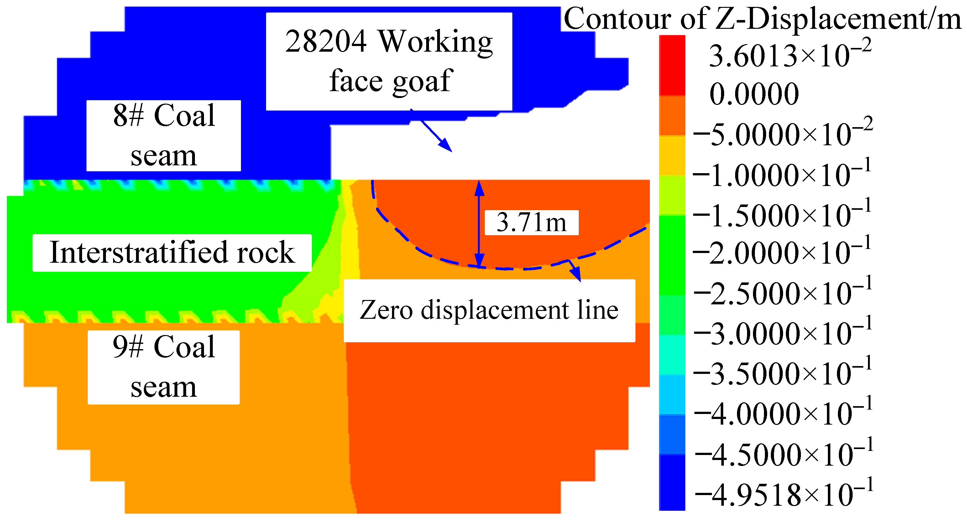
4.3.1. Simulation Verification of Floor Failure Mechanism

By excavating the upper 8# coal seam, Figure 9 shows the displacement variation characteristics of the upper coal seam floor.
Figure 9 shows that, after the excavation of the 8# coal, the floor displacement of the mining roadway in the 28204 working face presents obvious ‘zero displacement line’ characteristics, with a maximum floor heave of about 34.9 mm and a maximum failure depth of the zero displacement line of about 3.71 m, which is basically consistent with the floor failure depth of 3.742 m obtained according to the zero displacement line theory in the above analysis of the failure mechanism of the floor. Based on the above research, the failure mechanism of the floor is basically consistent.

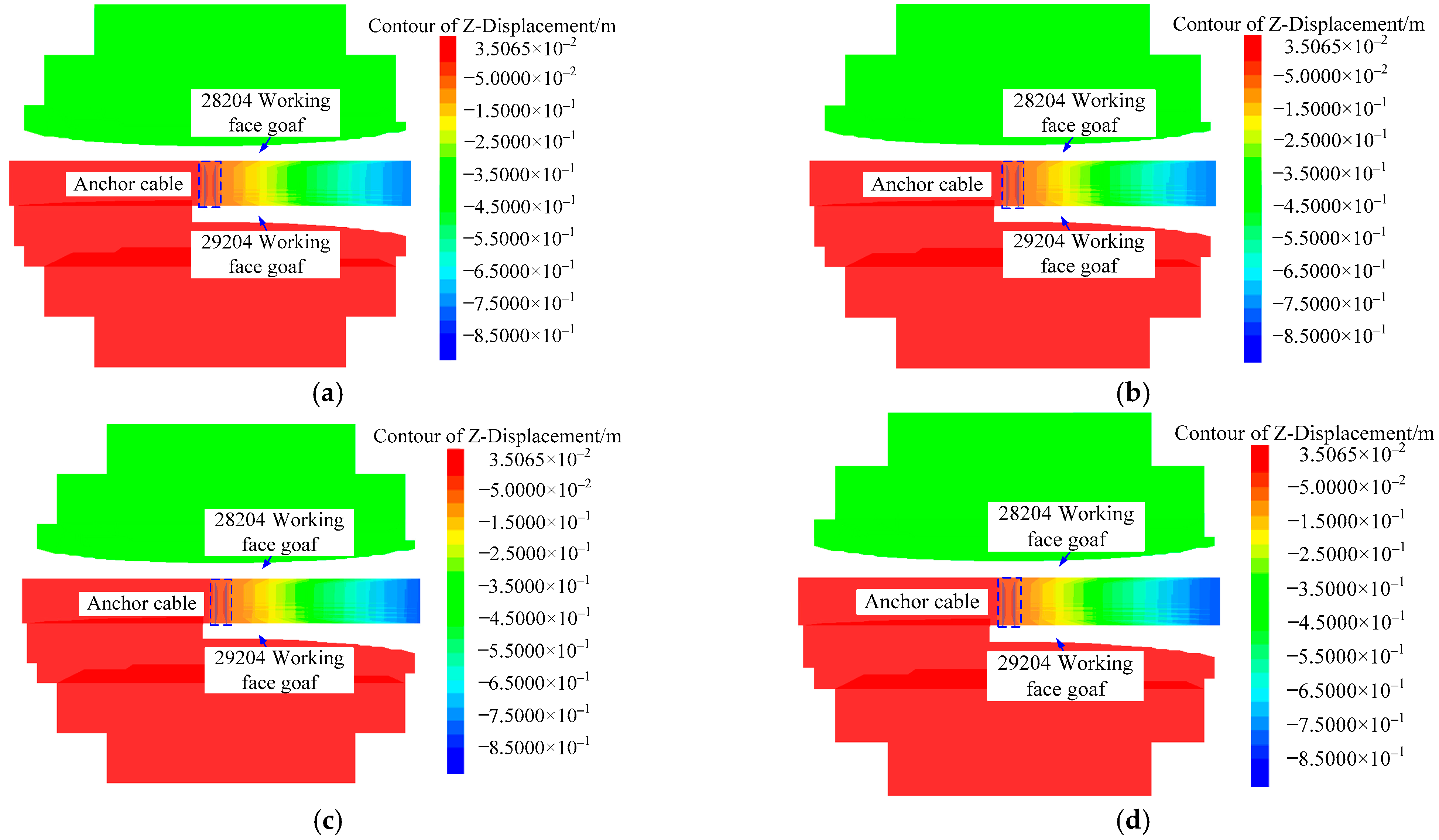
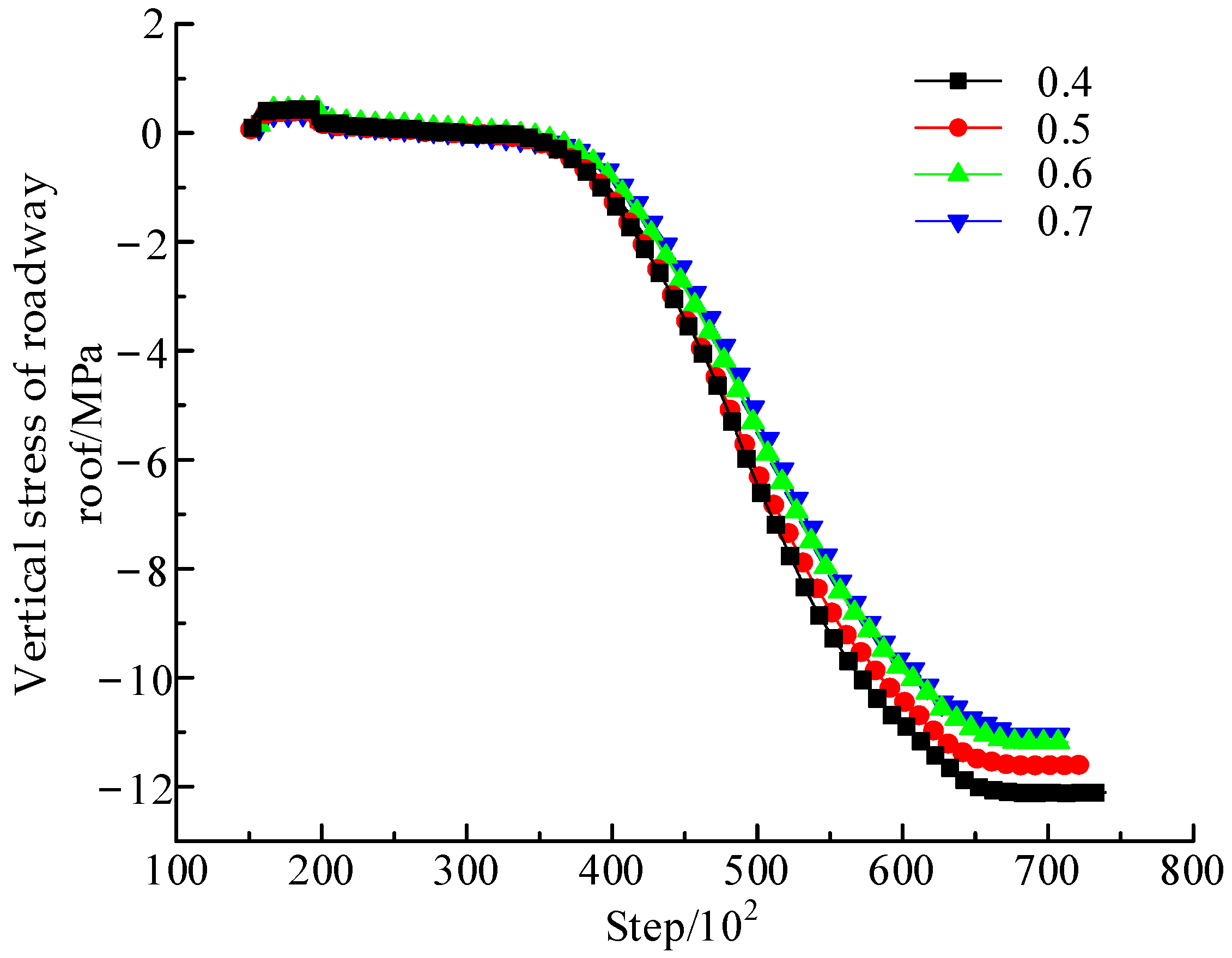
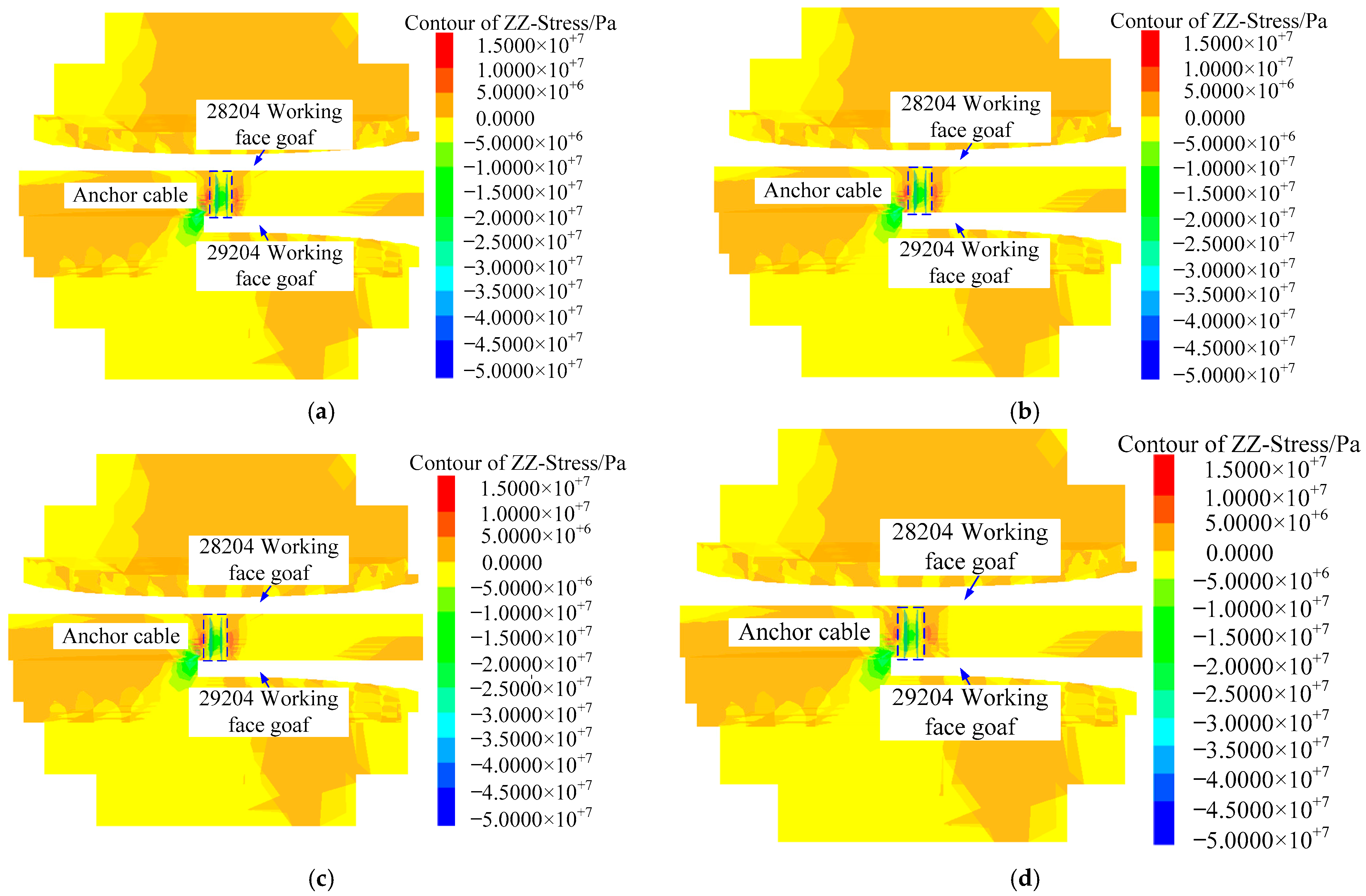
4.3.2. Deformation and Stress Distribution Law of Roadway Surrounding Rock under Different Water–Cement

The simulation results of vertical displacement of roadway roofs under different water–cement ratios are shown in Figure 10 and Figure 11.
From the influence of different water–cement ratios, when the water–cement ratio increases, the vertical displacement of the roof in the lower coal seam generally shows a trend of decreasing first and then increasing. For example, the water–cement ratio is 0.4, and the maximum subsidence of the lower coal roof is about 59.5 mm, the water–cement ratio is 0.5, the maximum subsidence of the lower coal roof is about 55.9 mm, the water–cement ratio is 0.6, the maximum subsidence of the lower coal seam roof is about 57.6 mm, and the water–cement ratio is 0.7, the maximum subsidence of the lower coal seam roof is about 60.8 mm. Therefore, from the minimum value of roof subsidence, the optimal water–cement ratio should be 0.5.
The results of vertical stress of the roadway roof under different water–cement ratios are shown in Figure 12 and Figure 13.
In close-distance coal seams, the vertical stress of roadway roofs varies with the water–cement ratio, the vertical stress of roofs in lower coal seams is inversely proportional to the water–cement ratio. For example, if the water–cement ratio is 0.4, the maximum vertical stress of the lower coal seam roof is about 12.4 MPa, if the water–cement ratio is 0.5, it is about 11.8 MPa, if the water–cement ratio is 0.6, it is about 11.5 MPa, and if the water–cement ratio is 0.7, it is about 11.4 MPa. From the perspective of the vertical stress of the roof, it is obvious that the vertical stress of the roof is the smallest when the water–cement ratio is 0.7.
To sum up, when the water–cement ratio is 0.5, roof subsidence is the smallest; however, the vertical stress is relatively high. On the other hand, when the water–cement ratio is 0.7, roof subsidence is relatively large; however, vertical stress is small. Therefore, considering the above factors and the required economic cost, the optimal water–cement ratio is 0.6.

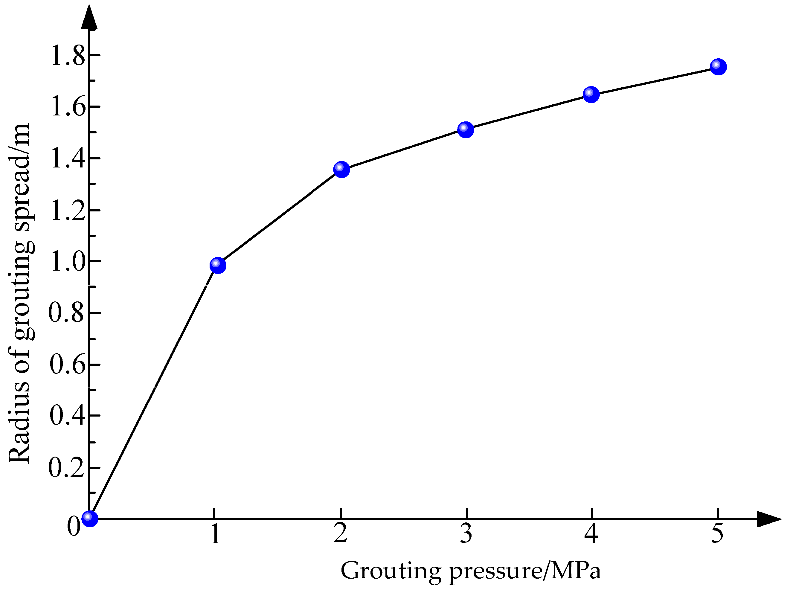
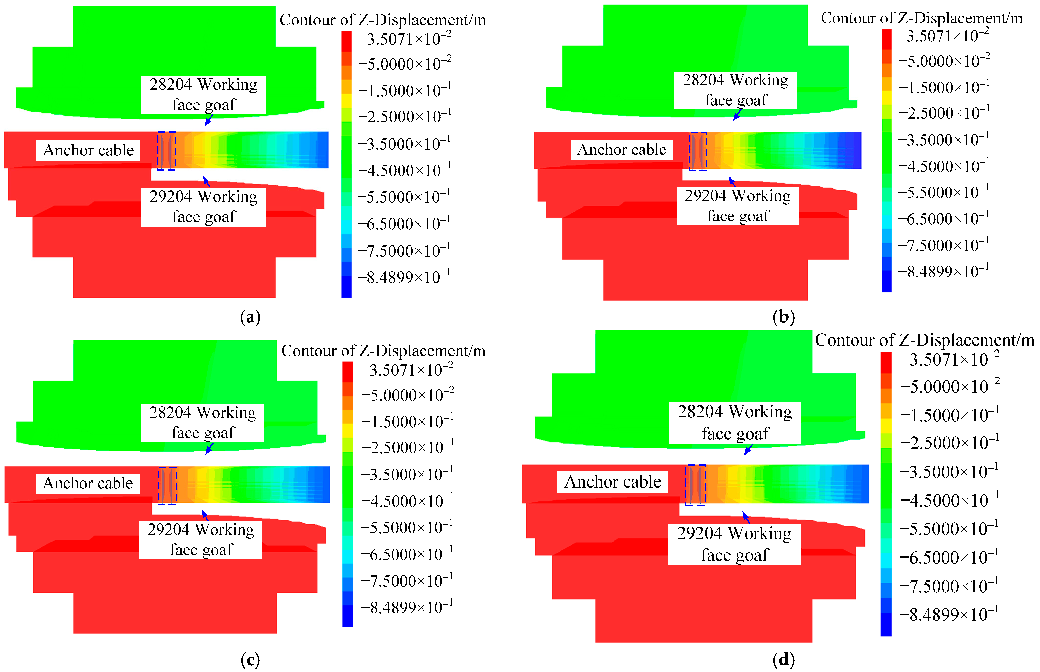
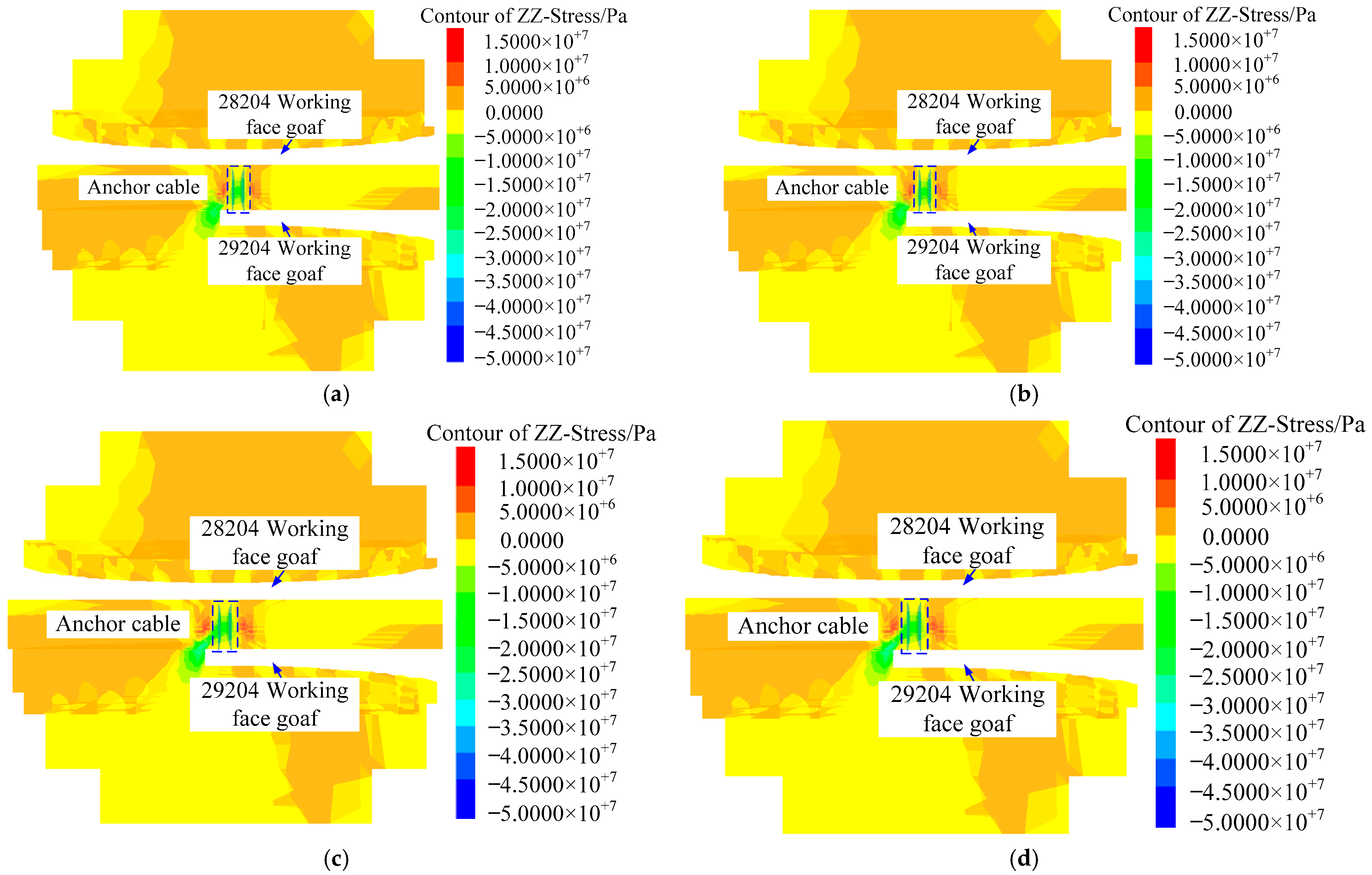
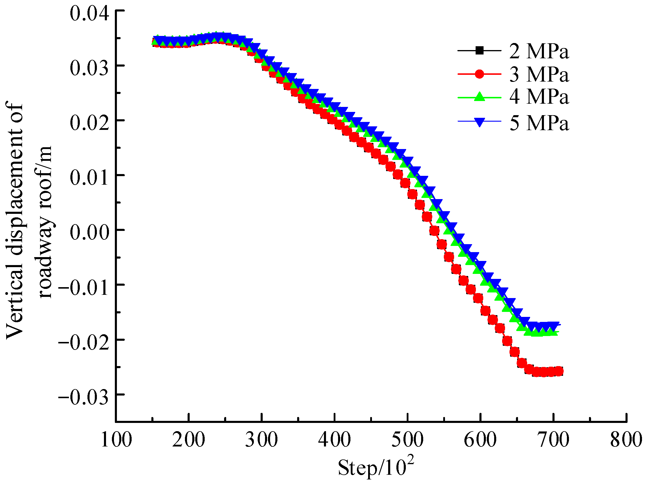
4.3.3. Deformation and Stress Distribution Law of Roadway Surrounding Rock under Different Grouting Pressure

The simulation results of vertical displacement of roadway roofs under different grouting pressure are shown in Figure 14 and Figure 15.
Lower coal seam roof vertical displacement generally decreases with increasing grouting pressure. For example, when grouting pressure is 2 MPa, the maximum subsidence of the lower coal seam roof is around 61.9 mm; when grouting pressure is 3 MPa, the maximum subsidence is about 60.8 mm; the maximum subsidence of the lower coal seam roof is about 53.9 mm when grouting pressure is 4 MPa and about 52.8 mm when grouting pressure is 5 MPa. Based on the minimum subsidence value, 5 MPa is the suitable grouting pressure. At the same time, referring to the allowable value of the actual roof subsidence in Dongqu Coal Mine, when the roof subsidence does not exceed 60 mm, it is most beneficial for the maintenance and use of the roadway. It can be seen that when the grouting pressure is 4 MPa or 5 MPa, the value of the roof subsidence can be met.
Figure 16 and Figure 17 show the vertical stress results of roadway roofs at different grouting pressures.
As grouting pressure continues to increase, the vertical stress on the lower coal seam roof generally increases gradually. The lower coal seam roof has a maximum vertical stress of about 11 MPa with a grouting pressure of 2 MPa, and a maximum vertical stress of about 11.3 MPa with a grouting pressure of 3 MPa. The maximum vertical stress of the lower coal seam roof is approximately 11.7 MPa when the grouting pressure is 4 MPa, and 11.9 MPa when the grouting pressure is 5 MPa. When the grouting pressure is 2 MPa, the vertical stress is the smallest, and the best control effect is achieved. Under different grouting pressures in a highway with a close-distance coal seam, the roof subsidence is larger when the grouting pressure is 2 MPa, and the control effect on the roof is the worst. There is the smallest roof subsidence on the 29204 working face at 4 MPa, and it decreases at the fastest rate. Although the vertical stress of the roof is relatively large at this time, it is basically the same as that under other grouting pressures in terms of growth amplitude.
Therefore, when grouting pressure is 4 MPa, the subsidence and vertical stress of the roof along the track are small, and the change rate has an obvious and beneficial inflection point. It can be seen that the optimal grouting pressure should be 4 MPa.

5. Field Application

The specific construction process includes construction preparation, drilling grouting anchor holes, installing grouting anchor cables, hole sealing and grouting, etc. The description of the construction process will not be introduced too much due to space reasons.
Based on the above research results, the optimum water–cement ratio and grouting pressure are determined to be 0.6 and 4 MPa, respectively, the spacing and row spacing of the cables are 1600 mm × 2000 mm, and the control group is set, which does not have the grouting cable support. The whole testing process continued from the working face 100 m away from the monitoring site to the working face advancing to the monitoring site, and the GUD350(A) surrounding rock movement sensor and GMY400 mine intrinsically safe anchor cable stress sensor were used for monitoring. The specific application effects are shown in Figure 18.
The results show that after the implementation of the scheme, the maximum displacement of the roof in the 29204 working face is about 42 mm, which is about 73.48 % lower than that of the control group. The overall change is relatively gentle, and the increase rate is small. The maximum cable force is about 50 kN, which is about 50.68% lower than that of the control group, and the overall change is relatively stable. A remarkable design effect can be seen in the cable support.

6. Conclusions

Based on the 29204 close-distance seam working face in Dongqu Mine, this paper revealed the failure mechanism of the upper coal floor and put forward the method of judging the integrity of the lower coal roof. Furthermore, this study optimized the design of the best support parameters by numerical simulation, which was verified by field cases. The main results are as follows:
(1)
A mechanical model for the failure of coal seams in close distances was developed, and the floor failure mechanism based on the zero displacement line was revealed. The method for theoretical calculation of floor failure was developed, and a method for evaluating the level of occurrence of lower seam roofs was proposed using yield ratios.
(2)
FLAC 3D numerical simulation was used to verify and optimize parameters. According to the results, the floor failure showed obvious ‘zero displacement line’ characteristics, which verified the feasibility of the model. At the same time, the vertical displacement and stress variation of roadway roofs under the influence of different water–cementation and grouting pressure were obtained, and the optimal water–cement ratio was 0.6 and the optimal grouting pressure was 4 MPa.
(3)
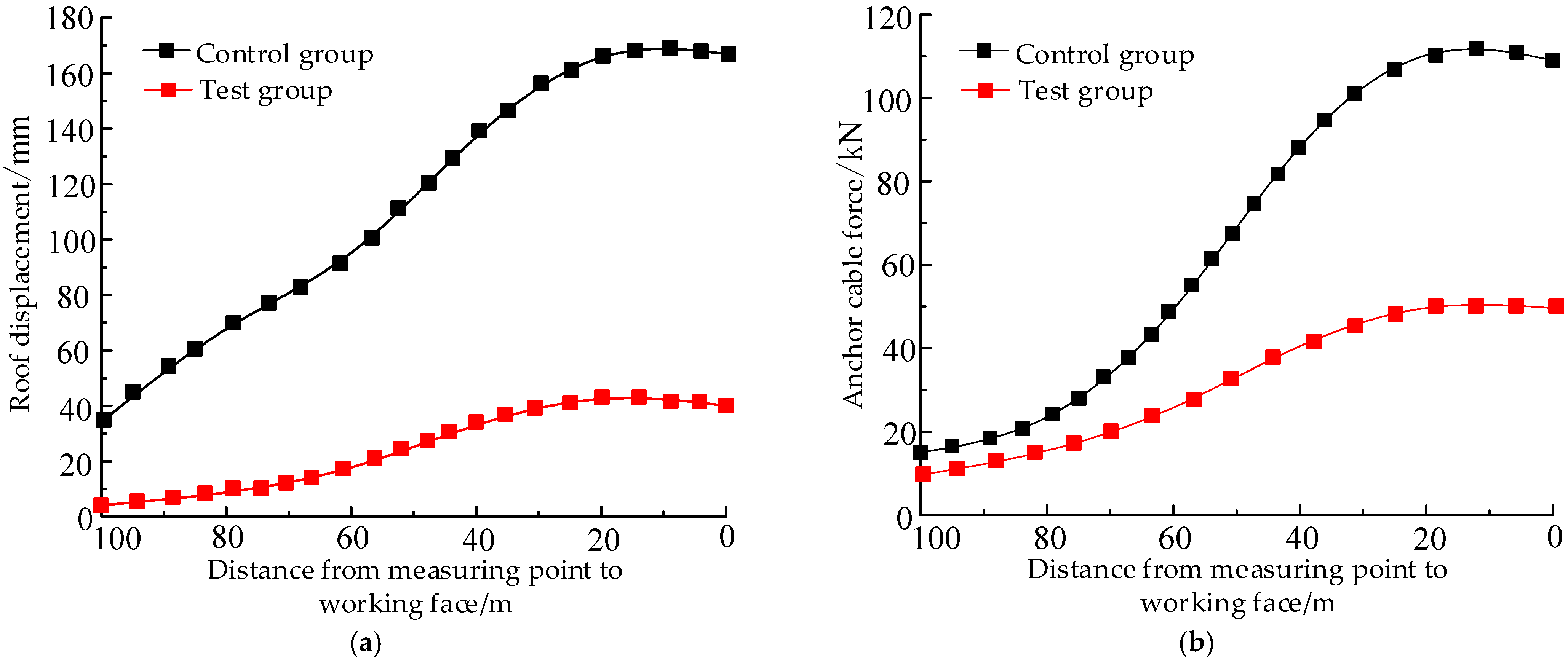
A field application was conducted for the 29204 roadway. As a result of monitoring, the maximum roof displacement of the 29204 working face was about 42 mm, which was 73.48% lower than that of the control group. About 50.68% of the maximum force of the cable was lower than that of the control group. Clearly, anchor grouting support had an impressive design effect. In the future, attention should be paid to the use of grouting anchor cable in the support selection of mining engineering, and the support parameters should be optimized and designed around factors such as mining and geological conditions, which are very beneficial to the safe mining of coal mines and the sustainable development of resources.

Author Contributions

Conceptualization, G.L.; methodology, G.L. and P.N.; software, P.N.; validation, P.N.; writing—original draft preparation, P.N.; writing—review and editing, G.L. All authors have read and agreed to the published version of the manuscript.

Funding

This research was funded by the National Natural Science Foundation of China (grant number 52174121).

Institutional Review Board Statement

Not applicable.

Informed Consent Statement

Not applicable.

Data Availability Statement

The data used to support the findings of this study are available from the corresponding author upon request.

Conflicts of Interest

The authors declare no conflict of interest.

References

  1. Zhang, Z.Z.; Deng, M.; Bai, J.B.; Yan, S.; Yu, X.Y. Stability control of gob-side entry retained under the gob with close distance coal seams. Int. J. Min. Sci. Technol. 2020, 31, 321–332. [Google Scholar] [CrossRef]
  2. Tan, Y.L.; Zhao, T.B.; Xiao, Y.X. In situ investigations of failure zone of floor strata in mining close distance coal seams. Int. J. Rock Mech. Min. 2010, 47, 865–870. [Google Scholar] [CrossRef]
  3. Yang, X.L.; Wen, G.C.; Dai, L.C.; Sun, H.T.; Li, X.L. Ground subsidence and surface cracks evolution from shallow-buried close-distance multi-seam mining: A case study in Bulianta Coal Mine. Rock Mech. Rock Eng. 2019, 52, 2835–2852. [Google Scholar] [CrossRef]
  4. Ma, Q.; Tan, Y.L.; Liu, X.S.; Gu, Q.H.; Li, X.B. Effect of coal thicknesses on energy evolution characteristics of roof rock-coal-floor rock sandwich composite structure and its damage constitutive model. Compos. Part B-Eng. 2020, 198, 108086. [Google Scholar] [CrossRef]
  5. Song, D.Q.; Chen, Z.; Dong, L.H.; Tan, G.J.; Zhang, K.L.; Wang, H. Monitoring analysis of influence of extra-large complex deep foundation pit on adjacent environment: A case study of Zhengzhou City, China. Geomat. Nat. Hazards Risk 2020, 11, 2036–2057. [Google Scholar] [CrossRef]
  6. Li, S.F.; Chen, J.F. Research on supporting technology of roadway surrounding rock for downward mining in extreme contiguous seams. Min. Saf. Environ. Prot. 2022, 49, 127–131. [Google Scholar]
  7. Zheng, W.X.; Bu, Q.W.; Hu, Y.Q. Plastic failure analysis of roadway floor surrounding rocks based on unified strength theory. Adv. Civ. Eng. 2018, 2018, 7475698. [Google Scholar] [CrossRef]
  8. Liang, Z.Z.; Song, W.C. Theoretical and numerical investigations of the failure characteristics of a faulted coal mine floor above a confined aquifer. Mine Water Environ. 2021, 40, 456–465. [Google Scholar] [CrossRef]
  9. Huang, Q.X.; Hao, G.Q. Research on the floor failure range and its effects of entry. J. Xian Uni. Sci. Technol. 2018, 38, 51–58. [Google Scholar]
  10. Cheng, H.; Zhao, H.B.; Zhang, H.; Qin, F.Y.; Li, J.Y. Study on mechanism and prevention technology of floor heave of mining roadway in close distance coal seam. J. Cent. South Univ. 2022, 53, 1392–1405. [Google Scholar]
  11. Liu, C.K.; Ren, J.X.; Gao, B.L.; Song, Y.J. Support design and practice for floor heave of deeply buried roadway. IOP Conf. Ser. Earth Environ. Sci. 2017, 64, 1232. [Google Scholar] [CrossRef]
  12. Sun, J.; Wang, L.G.; Zhao, G.M. Stress distribution and failure characteristics for workface floor of a tilted coal seam. KSCE J. Civ. Eng. 2019, 23, 3793–3806. [Google Scholar] [CrossRef]
  13. Chen, P. Analysis on stress characteristics of roadway floor and evolution law of arch structure. Coal Technol. 2020, 39, 79–81. [Google Scholar]
  14. Zhao, H.B.; Liu, Y.H.; Li, J.Y.; Xu, J.F. Analysis of damage process and zonal failure characteristics of rock mass under floor of isolated coal pillar. J. China Uni. Min. Technol. 2021, 50, 963–974. [Google Scholar]
  15. Jiang, Y.L.; Cai, T.T.; Zhang, X.Q. A multifactor coupling prediction model for the failure depth of floor rocks in fully mechanized caving mining: A numerical and in situ study. R. Soc. Open Sci. 2019, 6, 190528. [Google Scholar] [CrossRef] [Green Version]
  16. Wang, P.X.; Liu, J.N.; Feng, G.R. Stress distribution and failure characteristics of a longwall panel floor with a negative gate pillar. Chin. J. Rock Mech. Eng. 2023, 42, 194–211. [Google Scholar]
  17. Mo, S.; Sheffield, P.; Corbett, P.; Ramandi, H.L.; Oh, J.; Canbulat, L.; Saydam, S. A numerical investigation into floor buckling mechanisms in underground coal mine roadways. Tunn. Undergr. Space Technol. 2020, 103, 103497. [Google Scholar] [CrossRef]
  18. Liu, S.L.; Liu, W.T.; Shen, J.J. Stress evolution law and failure characteristics of mining floor rock mass above confined water. KSCE J. Civ. Eng. 2017, 21, 2665–2672. [Google Scholar] [CrossRef]
  19. Yin, S.X.; Meng, H.P.; Qian, S.B. Failure analysis of deep coal seam floor considering strain softening of surrounding rock and formation contact in goaf. Coal Geol. Explor. 2022, 50, 95–102. [Google Scholar]
  20. Ma, K.; Sun, X.Y.; Tang, C.A.; Yuan, F.Z.; Wang, S.J.; Chen, T. Floor water inrush analysis based on mechanical failure characters and microseismic monitoring. Tunn. Undergr. Space Technol. 2021, 108, 103698. [Google Scholar] [CrossRef]
  21. Lu, Y.L.; Wang, L.G. Numerical simulation of mining-induced fracture evolution and water flow in coal seam floor above a confined aquifer. Comput. Geotech. 2015, 67, 157–171. [Google Scholar] [CrossRef]
  22. Guo, G.Q. Floor failure law of extra-thick coal seam in fully mechanized caving mining. Coal Geol. Explor. 2022, 50, 107–115. [Google Scholar]
  23. Guo, G.Q.; Wang, Z.M.; Qu, S.B.; Li, H.; Zhou, Y.; Lyu, H.J.; He, Y. Study on explicit-implicit simulation and in-situ measurement of floor failure law in extra-thick coal seams. Minerals 2023, 12, 1511. [Google Scholar] [CrossRef]
  24. Meng, X.X.; Liu, W.T.; Zhao, J.Y.; Ding, X.Y. In situ investigation and numerical simulation of the failure depth of an inclined coal seam floor: A case study. Mine Water Environ. 2019, 38, 686–694. [Google Scholar] [CrossRef]
  25. Ning, J.G.; Wang, J.; Tan, Y.L.; Xu, Q. Mechanical mechanism of overlying strata breaking and development of fractured zone during close-distance coal seam group mining. Int. J. Min. Sci. Technol. 2020, 30, 207–215. [Google Scholar] [CrossRef]
  26. Hu, Y.B.; Li, W.P.; Liu, S.L.; Wang, Q.Q. Prediction of floor failure depth in deep coal mines by regression analysis of the multi-factor influence index. Mine Water Environ. 2021, 40, 497–590. [Google Scholar] [CrossRef]
  27. Liu, Y.B.; Wang, E.Y.; Jiang, C.B.; Zhang, D.M.; Li, M.H.; Yu, B.C.; Zhao, D. True triaxial experimental study of anisotropic mechanical behavior and permeability evolution of initially fractured coal. Nat. Resour. Res. 2023, 32, 567–585. [Google Scholar] [CrossRef]
  28. Liu, Y.B.; Wang, E.Y.; Li, M.H.; Song, Z.L.; Zhang, L.; Zhao, D. Mechanical response and gas flow characteristics of pre-drilled coal subjected to true triaxial stresses. J. Nat. Gas Sci. Eng. 2023, 111, 204927. [Google Scholar] [CrossRef]
  29. Lei, M.F.; Peng, L.M.; Shi, C.H. Calculation of the surrounding rock pressure on a shallow buried tunnel using linear and nonlinear failure criteria. Autom. Constr. 2014, 37, 191–195. [Google Scholar] [CrossRef]
  30. Xu, H.F.; Gen, H.S.; Li, C.F.; Chen, W.; Wang, C. Estimating strength of grouting reinforced bodies in broken rock mass. Chin. J. Geotech. Eng. 2013, 35, 2018–2022. [Google Scholar]
  31. Wang, L.G.; Miao, X.X.; Dong, J.T.; Tan, X.N. Numerical simulation research of bolt-grouting support in deep soft roadway. Rock Soil Mech. 2005, 26, 983–985. [Google Scholar]
  32. Li, L.H. Study on the Application of Advance Support Technology with Grouting and Cable in Mining Roadway. Master’s Thesis, China University of Mining and Technology, Xuzhou, China, June 2020. [Google Scholar]
  33. Song, D.Q.; Liu, X.L.; Huang, J.; Zhang, Y.F.; Zhang, J.M.; Benedict Nganteh, N. Seismic cumulative failure effects on a reservoir bank slope with a complex geological structure considering plastic deformation characteristics using shaking table tests. Eng. Geol. 2021, 286, 106085. [Google Scholar] [CrossRef]
Figure 1. Roadway layout of working face 29204.
Sustainability 15 05420 g001
Figure 2. Comprehensive histogram of roof and floor.
Sustainability 15 05420 g002
Figure 3. Relationship between 8# and 9# coal seams.
Sustainability 15 05420 g003
Figure 4. Mechanical model of floor: I. Compression area; II. Expansion area; III. Compaction area.
Sustainability 15 05420 g004
Figure 5. Simplified stress diagram.
Sustainability 15 05420 g005
Figure 6. Numerical calculation model.
Sustainability 15 05420 g006
Figure 7. Arrangement of cable.
Sustainability 15 05420 g007
Figure 8. Relationship between grouting pressure and slurry diffusion radius of cable.
Sustainability 15 05420 g008
Figure 9. Displacement variation characteristics of floor.
Sustainability 15 05420 g009
Figure 10. Cloud chart of vertical displacement of roadway roof under different water–cement ratios: (a) 0.4; (b) 0.5; (c) 0.6; (d) 0.7.
Sustainability 15 05420 g010
Figure 11. Vertical displacement curve of roadway roof under different water–cement ratios.
Sustainability 15 05420 g011
Figure 12. Cloud chart of vertical stress of roadway roof under different water–cement ratios: (a) 0.4; (b) 0.5; (c) 0.6; (d) 0.7.
Sustainability 15 05420 g012
Figure 13. Vertical stress curve of roadway roof under different water–cement ratios.
Sustainability 15 05420 g013
Figure 14. Cloud chart of vertical displacement of roadway roof under different grouting pressure: (a) 2 MPa; (b) 3 MPa; (c) 4 MPa; (d) 5 MPa.
Sustainability 15 05420 g014
Figure 15. Vertical displacement curve of roadway roof under different grouting pressure.
Sustainability 15 05420 g015
Figure 16. Cloud diagram of vertical stress of surrounding rock of roadway under different grouting pressure: (a) 2 MPa; (b) 3 MPa; (c) 4 MPa; (d) 5 MPa.
Sustainability 15 05420 g016
Figure 17. Vertical stress curve of surrounding rock of roadway under different grouting pressure.
Sustainability 15 05420 g017
Figure 18. Application effects: (a) Variation diagram of roof subsidence; (b) Variation diagram of cable force.
Sustainability 15 05420 g018
Table 1. Classification of interbedded rock integrity in nearby coal seams considering yield ratio.
TitlePartingBroken, Crack PenetrationBlock Fracture
Yield ratio β β ≥ 1β < 1
Interlayer spacing z (m)z ≤ 0.50.5 ≤ z ≤ 1.51.5 < zf·h
Table 2. Mechanical parameters.
Lithologic CharactersDensity/kg/m3Bulk Modulus/GPaShear Modulus/GPaAngle of Internal Friction/°Cohesion/MPaTensile Strength/MPa
sandy mudstone25205.72.5228.43.864.57
limestone26506.23.4329.42.192.32
medium sandstone25806.83.9833.62.592.67
siltstone26206.73.8232.82.782.51
limestone26506.23.4329.42.192.32
marl22405.12.7830.22.173.18
mudstone24503.82.1326.71.722.13
8#coal16003.11.5724.21.651.52
sandy mudstone25205.72.5228.43.864.57
9#coal16003.11.5724.21.651.52
sandy mudstone25205.72.5228.43.864.57
Table 3. Numerical simulation scheme of different water–cement ratio.
SchemeWater–Cement RatioBulk Modulus/GPaShear Modulus/GPaAngle of Internal Friction/°Cohesion/MPaTensile Strength/MPa
10.4461.7204.1244.461.7673.12
20.5153.968.0440.430.8836.56
30.651.322.6836.415.4418.28
40.717.17.5632.47.729.14
Table 4. Numerical simulation scheme of different grouting pressure.
SchemeGrouting Pressure/MPaRadius of Grouting Spread/m
121.3
231.5
341.65
451.75
Disclaimer/Publisher’s Note: The statements, opinions and data contained in all publications are solely those of the individual author(s) and contributor(s) and not of MDPI and/or the editor(s). MDPI and/or the editor(s) disclaim responsibility for any injury to people or property resulting from any ideas, methods, instructions or products referred to in the content.

