Article

Particle-Size Effect of Nanoparticles on the Thermal Performance of Solar Flat Plate Technology

1
Energy Systems Engineering, Cyprus International University, 99258 Nicosia, Cyprus
2
Petroleum Engineering, Near East University, 99138 Nicosia, Cyprus
*
Author to whom correspondence should be addressed.
Sustainability 2023, 15(6), 5271; https://doi.org/10.3390/su15065271
Submission received: 7 February 2023 / Revised: 7 March 2023 / Accepted: 14 March 2023 / Published: 16 March 2023

Abstract

:
One of the cleanest and most efficient solar collector systems is the flat plate collector, which has applications in hot water production, drying, among others. Flat plate collectors have improved in terms of both their structural configurations and working fluids. Several studies have verified the comparatively higher efficiency of nanofluid-based flat plate collectors, relative to that of water and other thermal oils. Additionally, the influence of several nanofluid synthesis factors, such as volume fraction, pH, type of base fluid, hybridization, surfactants, and sonification, on the performance of these collectors has been highlighted in the literature. However, the effect of nanoparticle size on collector performance has received minimal research interest, despite its significant effect on both the cost of synthesis and the thermophysical properties of nanofluids. The uncertainties regarding the effect of nanoparticle size on thermal collectors have limited their practical applications. This study numerically investigates the effect of the nanoparticle size of silver (Ag) nanofluid with nanoparticle sizes between 20 nm and 100 nm on the performance of flat plate collectors. The effect of nanoparticle size on the mean fluid temperature resulted in a maximum temperature of 45.8 °C for the Ag-100 nm. An increase of 0.25 °C for the Ag-20 nm was recorded, relative to the Ag-100 nm. In addition, the Ag-100 nm was calculated to have resulted in the highest reduction in collector size (18.30%), relative to that of water.

1. Introduction

The bedrock of all human activities, be they economic, social, or environmental, is energy. It is the source for activities in agriculture, industry, transportation, leisure, and many more [1]. The development of cities and nations is predicated upon the production and consumption of energy. Over the years, fossil fuels have been the primary source of energy globally for meeting our energy needs, and this has resulted in harmful environmental consequences [2]. The health hazards from burning fossil fuels and the increase in the average global temperature (global warming) have become popular subjects of discourse. In addition, industrialization and population growth have placed more demand on fossil fuel production, which has led to depleting resources. These challenges have prompted a need for alternative energy sources. Renewable energy sources are considered inexhaustible, and harnessing them does not constitute environmental depletion; hence, their integration into global energy production has increased exponentially in the past decade [3]. The availability of renewable energy across geographical locations also enhances energy security for countries, in addition to reducing carbon emissions and air pollution [4]. Amongst all renewable energy sources, solar energy represents the most harnessed source due to its vast potential and the low cost of solar technologies as of late [2,3]. The data show that the potential of solar energy globally is 3,850,000 exajoules per year, which is more than enough to meet global energy needs for a year [5]. According to the International Energy Agency (IEA), the development of solar energy technologies will accelerate the energy security of countries and reduce the costs of mitigating global warming [6]. Solar collector and photovoltaic systems are some of the most utilized solar technologies with wide-ranging applications. Solar collector systems are a type of heat exchanger, which operates on the principle of heat transfer from a heat source (the sun hitting the collector system) and a fluid flowing through the collector pipes [7]. Solar collector systems are classified as either concentrating or non-concentrating. The non-concentrating type of solar collectors is further divided into evacuated tube collectors and flat plate collectors (FPCs). The latter has been used in widespread applications due to their comparatively low cost and simple configurations. The first FPC was designed in 1942 by Hottel and Woertz [8], and Hottel and Whiller [9] further analysed the FPC system. Their first FPC was made out of an absorber plate, a transparent cover, a working fluid in the collector pipe, and an insulator. This FPC was further improved upon in 1955 by incorporating selective black surfaces to absorb more radiation. The experiment by (reference) opened the door for more research on the effect of optical concentration in producing high-pressure steam. Over the past few decades, more attention has been paid to improving the thermal efficiency of FPCs through their structural configurations and the utilization of better working fluids for optimum heat absorption [10]. Some of the adjustments that have been suggested and tested via experiments on structural configurations for the thermal efficiency enhancement of FPCs include the use of polymers to reduce the weight of the entire system [11], spacing between the glass covers in multi-glazed collectors (reference), modifications of absorber plates [12], and modifications of insulator materials to reduce the heat loss from the system [13]. However, even though there are several optimization procedures to increase the efficiency of FPCs, studies have shown that there is only a minimal enhancement achieved in these procedures. The alternative approach to enhancing the thermal efficiency of FPCs is optimizing the heat from solar resources using thermally improved fluids. In this vein, the direction of the study of heat transfer fluids for FPCs has shifted to nanofluids. Nanofluids are suspensions of nanoparticles with nanosizes below 100 nm in base fluids [14]. The comparative advantage of nanofluids over base fluids is their better thermal conductivity. This is due to their high size-to-volume ratio. The heat transfer characteristics of nanofluids have grown over the years since the first nanofluid was proposed by Choi [15]. Improvements in the thermal and physical properties of nanofluids, such as thermal conductivity, viscosity, and specific heat capacity (SHC), have been experimentally analysed in various studies by optimizing different synthesis variables. Certain studies have reported the significant effects of the preparation methods of nanofluids on their thermophysical properties [16]. Others have included volume concentration [17], temperature [18], nanoparticle type [19], hybridization [20], nanoparticle shape [21], the mixing ratio of nanoparticles [22], and centrifugation time [23]. These aforementioned factors have a direct impact on the performance of FPC systems when used as working fluids, as their effective utilization is measured based on the optimal extraction of heat from collector plates [24,25]. Several studies have specifically analysed the range of performance of FPCs by analysing the variations in the corresponding factors of nanofluid synthesis processes. Tajik et al. [26] considered how volume concentration affects the performance of FPCs. They prepared two volume concentrations of 0.05% and 0.1% Cu nanofluid. Their result showed that the collector efficiency of the FPC increased from 60% when using water to 70% and 80% with the 0.05% and 0.1% concentrations of the nanofluid, respectively. Additionally, the efficiency enhancement in the FPC was also recorded for the increased mass flow rate of the nanofluid in the collector pipe. A similar experimental study on the effect of volume concentration on the amelioration of FPCs was conducted by Mahmoud and Gyula [27]. In their study, the range of volume fractions was 0.0167%, 0.0333%, and 0.0666% WO3/water nanofluid. Their study found that the optimum efficiency enhancement of the FPC was 13.48% for a volume fraction of 0.0666%. The shape effect of nanoparticles on FPC performance was investigated by Khetib et al. [25]. It is worth noting that their study represents only a few studies that have considered the impact of the shape factor of nanoparticles on FPCs. Their study investigated the shapes of a brick, platelet, blade, and cylinder of boehmite–alumina nanoparticles. Their study showed that the platelet-shaped nanoparticle resulted in the least increase in outlet temperature from the pipe. Their study also showed that the brick-shaped nanoparticle resulted in a higher outlet temperature for the collector system. The potential of reducing the size of FPCs by utilizing nanofluids as heat transfer fluids was investigated by [28]. Their study investigated the effect of the mass fraction of nanoparticles and the presence of surfactants in a fluid. They measured a size reduction of 37% when a nanofluid was used against water as the working fluid. Their result also showed that the presence of a surfactant in the synthesis process of the MWCNT nanofluid used in their study improved its heat transfer characteristics. Moravej et al. [24] also analysed how TiO2 operated in an FPC. Their result showed that the optimal efficiency of the experimental FPC was recorded with a 1 wt% TiO2/water nanofluid. Their result had a maximum and average efficiency gain of 9.8% and 6.64% against water as a baseline, respectively. Additionally, their study found that the efficiency gains measured for 5 wt%, 3 wt%, and 1 wt% were 33.54%, 27.09%, and 27.09%, respectively. Yacine et al. [29] analysed the effects of incorporating a turbulator with innovative geometry (TIG) and a DWCNT/TiO2 hybrid nanofluid on an FPC. Their study analysed Reynold numbers between 7000 and 28000. Their findings demonstrated that by enhancing Re, the average Nusselt number rises. Additionally, the installation of TIG with PR = 4 within the solar collector (SC) raises the Nuave by 63.46 per cent at Re = 28,000 and = 3 per cent. A hybrid nanofluid of SiO2/TiO2 was used as the heat transfer fluid for the numerical investigation of the efficiency of an FPC in a study by Nidal et al. [30]. Their study showed that the SiO2/TiO2 outperformed the TiO2 nanofluid, and had an efficiency enhancement of 63.1% at a 4 wt% volume concentration. A study by Abassi et al. [31] investigated the performance of an FPC using a ZnO/water nanofluid. Their study synthesized nanoparticles at a size of 40 nm and at a volume concentration of 0.4%. Their result showed that the maximum improvement (16%) was recorded for the nanofluid-based FPC at a mass flow rate of 1 kg/min against water. Table 1 shows some improvements in the performance of FPCs with varying synthesis factors used in the preparation of nanofluids.

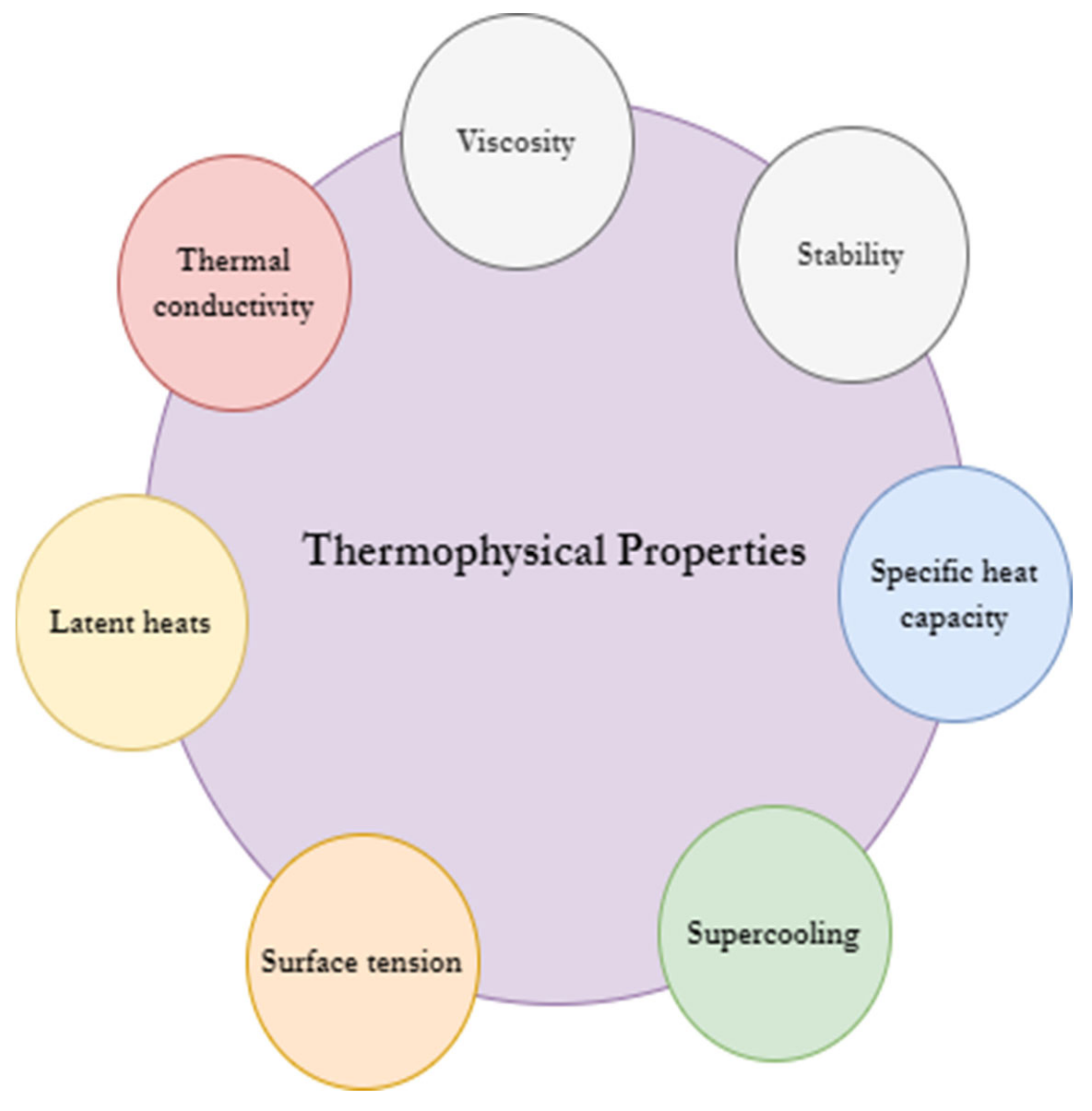
2. Effect of Nanoparticle Size (NPS) on Thermophysical Properties

The influence of the morphology of nanoparticles in the application of nanofluids is quite significant; however, there are only a few studies that have singularly considered utilizing varying nanoparticle sizes to investigate the extent of these effects. The variations and inconsistencies in this subject matter present an impression that more research is needed to clarify certain results. The influence of the sizes of nanoparticles is even more important for their use in practical applications because the cost of the synthesis of nanofluids is significantly affected by the synthesis of the optimal size. Furthermore, the effect of larger-sized nanoparticles is the clogging of the heat exchanger microchannel. This causes a high-pressure drop in the system and prevents effective flow in the channel. There is also the issue of erosion in the pipes with large-sized particles. Nanoparticles affect different thermophysical properties, as shown in Figure 1.
The study by Wang et al. [15] in 1999 was the earliest experimental analysis that mentioned that there could be a relationship between thermal conductivity and particle size. In their study, they found that with decreases in particle size, the thermal conductivity increased. They also stated that the dispersion technique, microscopic motion, and particle structure affected the variations in the thermal conductivity behaviour of the nanofluid. They suggested further studies on nanometer-sized particles for a better understanding of the use of nanofluids as a heat transfer medium. The effect on the thermal conductivity of Al2O3 nanoparticles with a range of nano sizes between 11 nm and 150 nm was analysed by Chon et al. [39]. Their study experimented with nanoparticles over a temperature range of 21–71 °C. Their study validated a previously proposed conjecture of Jang and Choi that the Brownian motion of nanoparticles affects the thermal conductivity of a nanofluid, with an increasing temperature and decreasing nanoparticle size. Their study presented a correlation Equation (Equation (1)) of the relationship between the nanoparticle size and temperature on thermal conductivity.
K e f f K B F = 1 + c o n s t . 1 d p 0.369 T 1.2321 10 2.4642 B T C
A study by Teng et al. [40] also investigated the effect of nanoparticle size on the thermal conductivity of an Al2O3 nanofluid. The sizes experimentally analysed were 20 nm, 50 nm, and 100 nm across volume concentrations of 0.5, 1.0, 1.5, and 2.0 wt.%. Their study corroborated the prevalent conclusion in the literature that thermal conductivity increases with decreases in particle size at a specific weight fraction. Chopkar et al. [41] analysed Al2Cu and Ag2Al nanoparticles and measured similar results to those of Teng et al. [40]. Beck et al. [42] investigated a much wider range of nanoparticle sizes between 8 nm and 282 nm. Their study made an interesting contribution to the enhancement in thermal conductivity in regards to nanoparticle size. Their study experimentally discovered that the thermal conductivity enhancement decreased below 50 nm, due to the particle size becoming small enough to be impacted by increasing phonon scattering, which decreases the thermal conductivity of the nanoparticles themselves. Pramod et al. [43] analysed the effect of the particle size of metallic nanoparticles on thermal conductivity. They found contrasting results to those of most studies. Thermal conductivity was shown to decrease with a decrease in particle size. Their study attributed this behaviour to the aggregation (which causes sedimentation) of smaller-sized particles.
The viscosity property of nanofluids is also affected by nanoparticle size. Different studies have shown differing results for the viscosity of nanofluids across varying sizes of nanoparticles. A study by Nguyen et al. [44] investigated the effect of temperature and nanoparticle size on the viscosity of Al2O3 and CuO nanofluids. According to their findings, for particle volume fractions that are smaller than 4%, the viscosities that correspond to an alumina–water nanofluid with particle sizes of 36 nm and 47 nm are nearly equal. The viscosities of 47 nm particles are unquestionably larger than those of 36 nm particles for higher particle fractions. A contrasting result by Lu et al. [45] showed that the viscosity decreased with increases in particle size.
From our literature review, which has shown little research on the effect of nanoparticle size on the performance of FPCs, and the few research studies available on thermophysical property behaviour of varying nanoparticle sizes, it is clear that more attention and studies should be conducted on the effects of nanoparticle size. Our study fills this gap by analysing the performance of FPCs with different nanoparticle sizes, alongside the effects of mass flow rate and meteorological parameters. This study also presents the first economic and environmental analysis of nanoparticle-sized heat transfer fluids in the literature. This study will serve as a significant reference for future discourse on the choice of heat transfer fluids for FPC systems. This paper is structured as follows: the next section discusses the nanofluid utilized for the numerical analysis (synthesis method). Section 4 presents the thermodynamic computation of the numerical analysis. Then the model validation is shown and the results are presented. This study concludes with a suggestion for future studies regarding nanoparticle sizes for FPCs.

3. Nanofluid Used for Analysis

The choice of nanofluid used in this study was based on the availability of complete and accurate data in the literature. The study from which the nanofluid was culled was conducted by Dhairiyasamy et al. [46]. The silver (Ag) nanoparticle was used due to a gap in the literature on the synthesis of silver (Ag) nanoparticles. The synthesis method was a two-step process. The base fluid used was ethylene glycol/water at a mixture ratio of 50:50. In preparing the Ag nanofluid, the nanoparticle (which was 20 nm) was mixed with the base fluid and sodium citrate in a magnetic stirrer and ultra-sonicated for a couple of hours to prevent coagulation and ensure the stability of the mixture. The 0.5% volume concentration was put into an ultrasonic bath to resist sedimentation. The same synthesis procedure was carried out for the different nanoparticle sizes of 30 nm, 40 nm, 60 nm, and 100 nm.
To observe the morphology of the silver nanoparticles, the transmission electron morphology (TEM) was analysed. It was shown from the results that the nanoparticles had spherical shapes. Furthermore, the aggregation results of the particles revealed that the larger particles had higher aggregation as compared to that of the smaller particles.
Stability analyses are important, especially when nanofluids are to be used as the working fluid in pipe systems. The stability of nanofluids is affected by the sedimentation of the nanoparticles. In determining the stability, the zeta potential test was used. The results showed a stability of 46 mV, which is considered a high stability.
The thermophysical properties were measured after the synthesis. The thermal conductivity (TC) measurement was performed using the KD2 pro analyser. The instrument had an accuracy of ±5 to ±10%. The TC analysis used a temperature range of 35–75 °C. In measuring the viscosity of the nanofluid, the Brookfield viscometer/DV2TTM was utilized. The temperature range in which the viscosity measurement was taken was between 35 and 75 °C. For determining the specific heat capacity (SHC), Figure 2 shows the variations in the thermophysical properties of the Ag nanofluid with temperature for the different nanoparticle sizes. The thermal conductivity results showed that the maximum value was retrieved for the Ag-20 nm at a temperature of 75 °C. The higher TC at a higher temperature agrees with the conclusions of the literature regarding the effect of Brownian motion on the conductivity of nanofluids. The result of viscosity analysis showed that a smaller nanoparticle size increases the viscosity property. This behaviour was attributed to the collisions of smaller particles in the base fluid, as compared to those of the larger nanoparticles. Additionally, the result showed that by decreasing the temperature across the range considered, the viscosity of the nanofluid increases, and this was attributed to the decrease in the particle interaction. Increasing the temperature causes an increase in the molecule’s kinetic energy, decreasing the viscosity. The increase in nanoparticle size results in a decrease in the specific heat capacity of the Ag nanofluid, while increasing the temperature also increases the SHC. The Ag-100 nm showed the lowest reduction in the specific heat measured. At 35 °C, the specific heat values of Ag-20 nm and Ag-100 nm decreased by 24 and 29 per cent, respectively, in comparison to base fluid values. For the Ag-20 nm sample, the specific heat value decreased by 19%, while for the Ag-100 nm sample, the specific heat value decreased by 23% at 75 °C.

4. Solar Flat Plate Collector Configuration and Mathematical Modelling

This study uses the model of Hottel and Whillier (HW) reported by Duffie and Beckman [47] for computing the analysis of the flat plate collector (shown in Figure 2) running with nanofluid as the heat transfer fluid. Some adjustments are made to their design. Table 2 presents the configuration of the FPC. In simplification of their model, some assumptions are also made, without distorting the fundamental concepts. These assumptions are as follows:
  • A steady-state operation of the FPC is assumed in the analysis and discussion;
  • There is uniform temperature across the tubes;
  • Temperature gradients are treated discretely in the flow direction and along the Y-axis in the absorber plate (along the X-axis);
  • There is the assumption of thorough and long-term stability of the nanofluid;
  • The heat losses are considered to be occurring from the absorber plate, concerning the bottom, top, and edge of the FPC. In addition, heat loss is occurring at the average temperature of the ambient temperature;
  • There is a uniform and unidimensional flow of the heat transfer fluid and heat, respectively.
Table 2. Specification and dimensions of the utilized FPC [48].
Parameters of Flat Plate CollectorSpecifications
Collector area2 m2
Length of plate2 m
Width of collector plate1 m
Height of collector plate0.15 m
Collector tilt angle15
Back insulation thickness0.05 m
Edge insulation thickness0.025 m
Absorber plate thickness0.00045 m
Thermal conductivity of absorber plate386 W/m k
Emissivity of absorber plate0.95
Effective transmittance–absorptance product0.82
Thickness of glass cover0.004 m
Absorptivity of glass cover0.05
Emissivity of glass cover0.88
Tube spacing between risers0.095 m
Riser pipe’s inner diameter0.0095 m
Riser pipe’s outer diameter0.01 m
Diameter of header pipe0.0254 m

4.1. Mathematical Computation of the FPC

The operation of flat plate collectors involves trapping solar thermal energy, using a heat transfer fluid (water, thermal oil, phase change materials, nanofluid), and using them in heating applications, such as water heating, drying, space heating, refrigeration process, and other industrial applications. The performance of FPCs is an important research topic as it helps in improving and developing their designs [11]. The development and analysis of FPCs work in tandem. Carrying out experimental analysis is most often not feasible, especially at the early stage of a design improvement, due to cost. Hence, analytical and numerical methods can be employed.
The performance analysis of FPCs is usually computed using the first law and second laws of thermodynamics. The first law of thermodynamics is known as energy efficiency, while the second law is known as exergy efficiency, which most often has smaller values due to the irreversibility of the process, which destroys part of the input energy [49]. To estimate the useful energy gained from a collector using the solar radiation magnitude, Equation (2) is computed [50].
Q u = A c S U L T p m T a
In Equation (2), the area of the collector system is represented by A c , while the solar irradiance incidence on the plate, plate temperature, and ambient temperature are depicted using S, T p m , and T a , respectively. Additionally, U L explains the coefficient of heat loss from the FPC. Equation (3) gives the mathematical derivation of computing the U L [51].
U L = U t + U b + U e
Experimental studies have shown that adding insulation to the sides and ends of the FPC drastically drops the heat loss from the system, thereby improving the overall performance. Equations (4) and (5) show the numerical calculation of the bottom and side of the collector system in terms of heat loss coefficient.
U b = L b K b + 1 h b , a 1
U e = L e K b + 1 h b , e 1 A e A c
The thickness, thermal conductivity, and heat transfer by convection of the side and back of the collectors are represented using L e , h b , e , and L b , K b , and h b , a , respectively.
In computing the performance of the FPC, this study used the fin analysis explained in the studies by [52,53]. Equation (6) is used to calculate the mean fluid temperature of the HTF [54].
T p m = T i + Q ˙ u A c × U L × F R × 1 F R
In the estimation using Equation (6), a constant inlet temperature ( T i ) of 305.15 K is used in this study. F R represents the heat transfer factor. Equation (7) gives the mathematical computation of F R [55]:
F R =   m ˙ C P A c U L   1 e x p A c × U L × F m ˙ C P
The specific heat capacity of the fluid is represented using C P , while m ˙ and F are the mass flow rate and coefficient of collector efficiency, respectively. F is estimated using Equation (8) [55]:
F = w 1 D + W D F + U L π D i h f i 1
D explains the outer diameter of the tubes, while the distance from the center of the pipe to the middle point of the fluid is given by W [56].
F = t a n h m W D / 2 m W D / 2
By dividing the useful energy output by the area of the collector and the solar irradiation ( G T ) received on the collector system, the efficiency of the FPC is measured, as shown in Equation (10) [57]:
η = Q u A c G T
The pressure in the collector is computed using Equation (11), where the inclination angle is represented as follows:
Δ P = ρ f g L s i n β + h L
The pumping power used in circulating the fluid through the system is dependent on the viscosity of the fluid, and this further provides a useful comparative analysis with base fluid, in terms of the cost of using varying HTFs. Equation (12) gives the computation of the pump work [58]:
W p = m ˙ Δ P ρ f
The maximum output achievable from a system concerning the environment temperature is referred to as exergy. Equation (16) gives the general exergy balance [59,60].
E i n ˙ + E ˙ s + E ˙ o u t + E ˙ l + E ˙ d ˙ = 0 ˙ ˙ ˙
where the inlet exergy rate, stored exergy rate, outlet exergy rate, leaked exergy rate, and destroyed exergy rate are represented by E ˙ i n , E ˙ s , E ˙ o u t , E ˙ l , and E ˙ d , respectively. In estimating the inlet exergy rate, which computes the absorbed solar radiation rate and flow of the fluid, Equation (14) is used [60].
E i n , f = m ˙ ˙ C p T i n T a l n T i n T a + m ˙ Δ P i n ρ
where the pressure difference between the environment and the fluid is represented by Δ P i n . Equation (15) is used to compute the absorbed solar radiation exergy:
E i n , Q = η I T A p 1 T a T s ˙
The apparent temperature of the sun is given as T s . Equation (16) is used to compute the inlet exergy rate of the FPC:
E i n = E i n , f + E i n ,   Q ˙ ˙ ˙
The stored exergy rate is zero, considering steady-state conditions:
E ˙ s = 0
Equation (18) shows the mathematical computation of the outlet exergy rate [61]:
E o u t , f = m ˙ ˙ C p T o u t T a T a l n T o u t T a + m ˙ Δ P i n ρ

4.2. Economic and Environmental Analysis

The embodied energy of the FPC is estimated. The distribution, maintenance, and disposal of solar collectors are not taken into account; rather, only the energy required during the solar collector’s manufacturing process is taken into account. Because the manufacturing of the collector accounts for more than 70% of the system’s embodied energy [62], the calculation is made using the size reduction in the collector system; this computation is performed using Equation (19) [50]:
A p = m ˙ C p T o u t T i n I T η
The economic analysis parameter used in this study is cost savings, which is obtained by analysing the thermal performance and the FPC size reduction. Because of the higher performance of the nanofluid-based FPC, the collector geometry can be scaled on the overall percentage weight of the system. The cost offset from using the nanofluid as the working fluid is the cost savings. The energy utilized daily in tangent with the local electricity rates based on 0.055 USD/kWh (0.987TL/kWh) are used to determine the cost saved from refraining from using fossil fuel sources.
The main source of emission production (EP) in the Turkish Republic of North Cyprus (TRNC) is energy production in power plants. In 2008, North Cyprus produced 0.953 million tons of carbon emissions. Since 2018, there have been 1.27 million tons of CO2 emissions from the production of energy using fossil fuels (1631.041 million kWh) [63]. Table 3 shows the approximate release emissions per kWh in Cyprus by conventional power plants. Utilizing solar hot water systems instead of the burning of fossil fuels for heating water can reduce emissions on the island. The reduction in emissions can be estimated from the embodied energy index retrieved from the embodied energy analysis. The estimation is made for the main pollutants: CO2, NOx, and SOx.

5. Model Validation

The reliability of the proposed model for computing the performance of the nanofluid-based FPC in this study needs to be ascertained. The model validation is carried out using an experimental study by Mahmoud et al. [27], in which the nanofluid used as working fluid was WO3/water. The model in this study was also validated by an experimental investigation of FPCs by Alawi et al. [33], in which they utilized graphene nanofluid as the working fluid in a collector pipe. In both of the studies used in validating the designed model for this study, the parameters inputted into the model design included the collector configurations, mass flow rate, and volume concentration. Mahmoud et al. [27] found that the collector area was 1.009 × 2.009   m 2 .  Table 4, Table 5 and Table 6 show the experimental results and the modelled results. It can be seen that in Table 4 and Table 5, the maximum per cent error was 0.2052 and 0.6849, respectively. This low error shows the accuracy of the model developed in this study. Furthermore, it can be generally noted from the experiment results in Table 5 that the absorbed heat from the collector increased with increasing mass flow rate at a constant volume concentration. In addition, Table 5 shows that at a specified mass flow rate, the heat removed from the collector by the nanofluid increased with more nanoparticles in the base fluid. Additionally, Table 6 shows a close result between the outlet temperature of the nanofluid in the experiment conducted by [4] and the modelled result.

6. Results and Discussion

This section presents the simulation results of the nanofluid-based flat plate collector. As stated in previous sections, the main focus of this study specifically highlights the influence of the morphology of nanoparticles (specifically their size) on the heat transfer characteristics of nanofluids, which ultimately affect the thermal performance of the systems in which they are used (as working fluids). Some points are worth noting regarding the results presented from the numerical analysis. Firstly, the effect of nanoparticle size does not nullify the effects of other factors, such as the volume concentration, pH of the synthesis, base fluids, etc. It should be noted that the volume concentration of the nanofluid used in this study is set at 0.5%, and the base fluid is water. The ratio of the water and nanoparticle was also fixed at a 50:50 mixture ratio [5]. However, the result obtained in this study simply highlights the extent or magnitude of particle size. In addition, this is meant to emphasize the subject of nanoparticle size in future syntheses and practical applications. Moreover, the authors utilize just one nanofluid in this analysis; however, a similar methodology can be used to investigate nanofluids with varying nanoparticle sizes. This study also checks the performance of the FPC by varying the mass flow rate of the nanofluid, time of the day, and Reynold number. Furthermore, the meteorological parameters used in the simulation are obtained from the weather station at Cyprus International University (CIU), Turkish Republic of North Cyprus.
Figure 3 shows the retrieved ambient temperature and incident solar radiation across a typical day in summer at the case study location. The meteorological data were retrieved on 25 July 2022. Several studies [65] have exhaustively studied the effects of weather, such as solar radiation, humidity, and ambient temperature, on the performance of solar collector systems. Figure 3 shows that between the hours of 8 am and 1 pm, the solar radiation increases from 389 W/m2 to 920 W/m2 and then starts to drop till the evening hours. A similar trend is noted for the ambient temperature.
The performance of the FPC with the Ag nanofluid with nanoparticle sizes of 20 nm to 100 nm (Ag-20 nm, Ag-30 nm, Ag-40 nm, Ag-60 nm, and Ag-100 nm) is analysed above.
The mean fluid temperature of the FPC across the day is depicted in Figure 4. Figure 4 shows that the mean fluid temperature (computed using Equation (6)) has an increasing trend with the solar radiation, due to there being more solar energy available to be absorbed by the working fluid. Additionally, the useful energy extracted based on the Equation shows that this factor will increase with increasing solar radiation [66]. As for the effect of the nanoparticle size on the mean fluid temperature, a maximum temperature of 45.8 °C was measured for the Ag-100 nm. An increase of 0.25 °C between the Ag-20 nm and Ag-100 nm was found. It is also worth noting that the difference in the mean temperature increased as the nanoparticle size increased. For example, at 3 pm, the mean fluid temperatures of the Ag-20 nm and Ag-40 nm were 45.55 °C and 45.6 °C, respectively, while the mean fluid temperatures of the Ag-60 nm and Ag-100 nm were 45.7 °C and 45.8 °C, respectively. The percentage difference between the former and latter nanoparticle pairs was 0.11% and 0.22%, respectively.
The fluid outlet temperature of the FPC is shown in Figure 5. A similar trend as that of the mean fluid temperature is depicted. The fluid outlet temperature of the nanofluid is measured based on the absorbing ability of the nanofluid in the pipe. The heat from the glass cover is better absorbed by the Ag-100 nm, with the maximum temperature recorded being 49.4 °C at 2 pm. At the same time (2 pm), the least outlet temperature is measured for the Ag-20 nm with a temperature of 48.9 °C. This similar trend of increasing temperatures with an increase in nanoparticle size has been corroborated by a few studies in the literature regarding the higher thermal conductivity of larger-sized nanoparticles. One of these studies was conducted by Elena et al. [67], in which the thermal conductivity of a SiC nanofluid was investigated at different particle sizes between 16 nm and 90 nm. Their study had a similar range of nanoparticle sizes as that in this study. Their result showed that a larger particle size resulted in a higher thermal conductivity and lower viscosity compared to smaller-sized nanoparticles. The reason for this behaviour was stated to be the smaller solid/liquid interfacial area of the larger-sized particles. Their study mentioned that the heat transfer coefficient of nanoparticle sizes below 95 nm has been shown in the literature to have lower values than water [68,69,70]. Studies in the literature have shown that a heat transfer coefficient higher than the base fluids at a constant velocity results in larger nanoparticle sizes, such as the study of Xuan and Li [71] (Cu-100 nm), Devdatta et al. [70] (SiO2-100 nm), and Yurong et al. [72] (TiO2-95 nm). However, the outlet temperature of an FPC is more related to the specific heat capacity of the fluids, which is the energy required to raise the temperature of the fluid. This result can also be due to the higher nanoparticle size, which lowers the SHC of the nanofluid as compared to that of the smaller-sized nanoparticles. The preceding results from the useful energy and efficiency reports can better explain other thermophysical effects, such as thermal conductivity, on the FPC and the general performance of the modelled system.
Figure 6 shows the useful heat from the collector. The model shows that the useful heat has the same pattern as the solar radiation. Again, this is because of the higher amount of solar thermal energy available between the morning and midday. The useful heat results at 8 am for the Ag-20 nm, Ag-30 nm, Ag-40 nm, Ag-60 nm, and Ag-100 nm are 475.8 kW, 476,2 kW, 475.6 kW, 474.7 kW, and 473.7 kW, respectively. The maximum useful heat (1265 kW) was measured at 1 pm for the Ag-20 nm. The percentage increase in the useful heat between the smallest and largest particle sizes was 0.8% (at 2 pm).
The energy efficiency of the FPC at different NPSs is shown in Figure 7. The energy efficiency was computed using Equation (10). Since the energy efficiency is directly proportional to the useful heat extracted from the absorber plate of the collector, the pattern is similar to that in Figure 6. The energy efficiency increases with the decreasing nanoparticle size. The maximum efficiency (69.1%) was measured for the Ag-20 nm at 10 am. A possible reason for the maximum efficiency being recorded at this time is due to less heat loss from the collector as compared to that at midday when the temperature is much higher. At 10 am, the energy efficiencies recorded for the Ag-30 nn, Ag-40 nm, Ag-60 nm, and Ag-100 nmm were 69.0%, 68.86%, 68.0%, and 68.64%.
The increasing useful heat output and energy efficiency of the FPC with decreasing nanoparticle size are attributed to the enhanced TC of the smaller-sized particles. Kanti and Praveen [73] studied the thermophysical behaviour of coal fly ash nanoparticles with particle sizes between 11 nm and 114 nm. Their study showed that across varying temperature and volume fractions, smaller-sized nanoparticles showed a higher thermal conductivity (TC) and heat transfer enhancement as compared to larger-sized nanoparticles. Their study showed that there was an optimal 11.92% enhancement of the TC against the base fluid when the NPS was 11.5 nm, with a volume fraction and temperature of 0.5% and 60 °C, respectively. The viscosity was increased with decreasing NPS in their study, and this behaviour was explained to be a result of the higher interface resistance of the fluid layer of smaller-sized nanoparticles. It is important to note that this is a net negative to the FPC system.
The exergy efficiency of the FPC is numerically presented in Figure 8. The value of computing the exergy efficiency is that it shows the cause and scope of irreversibility, which can help improve the FPC performance. The maximal output possible given the temperature of the surroundings is known as exergy. Figure 8 shows the variation in exergy efficiency across the day, which has the same trend as solar radiation. The result shows that the exergy efficiency increases with more available solar resources. Farahat et al. [60] agree with this result, as their study examined the exergy efficiency of flat plate collectors. Their study showed that the exergy efficiency of the system increased from 0 to 6.9% when increasing solar radiation from 50 to 1000 W/m2. A similar result was also found in the study by Joseph et al. [48], in which the maximum exergy efficiency (68%) was recorded at noon, and then it decreased till 4 pm. The optimum exergy efficiency (2.08%) was noted for the 100 nm Ag nanoparticle. This was retrieved for 12 pm. The exergy efficiencies of the Ag-20 nm, Ag-30 nm, Ag-40 nm, and Ag-60 nm were 2.03%, 2.04%, 2.05%, and 2.06%, respectively.
In the design improvement of flat plate collectors, apart from the augmentation of heat transfer, the minimization of pressure drops and maximization of the ratio of heat transfer to pressure drops are important conditions to consider [74]. The pressure drop is a crucial factor to take into account since it determines how much power will be required to pump fluid through the system. Calculating the pressure drop and pumping power also aids in determining how engines handle their energy [63]. Figure 9a,b show the pressure drop with varying mass flow rates and times of the day, respectively. The pressure drop of all the nanoparticles considered showed a similar trend of increasing values with an increase in the mass flow rate. The pressure drop decreased with decreasing nanoparticle sizes (with the exception of the Ag-100 nm). The boundary layer is a thin layer of fluid that forms when a fluid flows over a surface and is close to the surface. Frictional drag between the fluid and the surface causes this layer to flow more slowly than the bulk fluid does [75]. Because of this, the fluid in the boundary layer is more pressurized and has a lower velocity than the bulk fluid. Nanoparticles can interact with the molecules of a fluid and change its properties, such as its viscosity and thermal conductivity, when they are added to it. Boundary layer thickness, which varies with particle size, can also be impacted by the inclusion of nanoparticles [76]. More interactions with fluid molecules are possible when the surface area of the particles increases due to a reduction in particle size. This contact may cause the fluid’s viscosity to decrease, which could lead to a reduction in the boundary layer’s thickness [67]. The fluid’s velocity in the boundary layer increases as the layer’s thickness decreases, which decreases the pressure drop. Furthermore, the presence of nanoparticles in the fluid can encourage turbulence and prevent eddies from forming, which can lower the pressure drop by reducing the creation of stagnant fluid patches that can obstruct flow. Reducing the size of the nanoparticles can reduce the boundary layer and increase turbulence, which lowers the pressure drop in the fluid flowing over a surface.
The viscosity of the fluid, the flow rate, the size, and the geometry of the channel are all factors that affect the pressure drop across a fluid flowing through a channel. The fluid pressure decrease may be impacted by the size and shape of the nanoparticles when they are added. The fluid becomes more viscous as the size of the nanoparticles grows because it is harder for them to pass through the channel. When the fluid moves through the channel, the pressure drop is increased due to the increased viscosity. This validates the reduced pressure drop with the decrease in nanoparticle size as seen with the 60 nm, 40 nm, 30 nm, and 20 nm Ag. The behaviour of the 100 nm nanoparticle size can be attributed to some other factors, such as agglomeration, surface charge, and flow rate. Agglomeration can affect the thermophysical properties, which can affect the result. It is worthy to note, however, that experimental analyses are needed to further clarify such theoretical and analytical results. Additionally, in an experimental setup, the channel size can also affect the pressure drop. The influence of nanoparticle size on the pressure drop may be less pronounced if the channel is quite large.
With an increase in the mass flow rate between 0.06 kg/s and 0.08 kg/s, the percentage increase in the pressure drop of the Ag-20 nm, Ag-30 nm, Ag-40 nm, Ag-60 nm, and Ag-100 nm was 33.80%, 33.81%, 33.82%, 33.78%, and 33.81%. The lowest pressure drop (734.3 Pa), which is a net positive for the FPC system, was measured for Ag-20 nm (0.06 kg/s mass flow rate), while the maximum pressure drop (1002 Pa) was measured for the Ag-60 nm at 0.08 kg/s. The higher pressure drop with increasing nanoparticle size is due to a higher amount of friction between the fluid and the wall of the pipe. A direct consequence of a high-pressure drop is an increase in the power required to pump the fluid through the pipe. Figure 10a,b show the pump work of the nanoparticles at varying mass flow rates and times of day, respectively. Figure 10a shows that the maximum pump work was measured for the Ag-60 nm with 0.072 W.
Table 7 shows the embodied energy from the different nanoparticle sizes based on the FPC. The result also shows the production of the different emissions. It can be seen that the Ag-100 nm resulted in the highest reduction in collector size (18.30%), relative to water. In addition, the embodied energy in production for the Ag-100 nm was the least, with 453.28 MJ. Environmental analyses are important for global efforts toward carbon emission reductions. Table 7 shows that the highest CO2 reduction, 442.858 kg, was measured for the Ag-100 nm, while the lowest CO2 reduction, 120.628 kg, was measured for the Ag-20 nm. The maximum reductions in SOx and NOx were 61.6% and 62%, respectively, which corresponded to the Ag-100 nm. Table 8 also shows the yearly damage costs of nanoparticle-size-based solar collectors. It can be seen that, relative to water, the Ag-100 nm resulted in the lowest damage costs: 7.428837, 1.579411, and 4.096075 USD/kg for CO2, SOx, and NOx, respectively. Water was measured to have the highest cost per kg of damage costs. This is attributed to the lower heat absorption capacity of water relative to that of nanofluids. Jaweed et al. [47] also agree with our measured results.

7. Summary of Findings and Conclusions

Our study fills a crucial research gap on nanoparticle size in the analysis of the thermal performance of solar flat plate collectors. The lack of research analysing this property of nanoparticles has hindered the practical application of nanofluids in collector systems, because there is not a clear understanding on the optimal nanoparticle size for efficient heat absorption, which can lead to higher costs for synthesis and the reduced performance of FPCs. This study has also mentioned that the emphasis on nanoparticle size does not nullify the effect of other factors, such as volume fraction, base fluid, pH, and hybridization, which have been studied extensively. However, the effect of nanoparticle size should be analysed side-by-side with these other effects in future numerical and experimental studies.
This study, therefore, investigated the thermal performance of FPCs: energy and exergy efficiency, fluid outlet temperature, pressure drop, pump work, and PEC factors. The economic and environmental implications of different nanoparticle-sized Ag nanofluids were also investigated. Some of the significant results retrieved from the numerical analysis include the following:
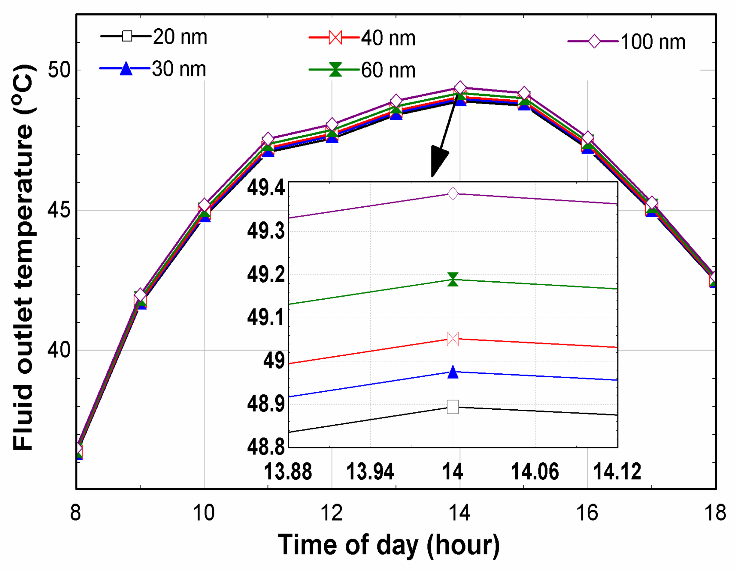
  • The effect of nanoparticle size on the mean fluid temperature was shown by a maximum temperature of 45.8 °C which was measured for the Ag-100 nm. An increase of 0.25 °C between the Ag-20 nm and Ag-100 nm was calculated;
  • The useful heat at 8 am for the Ag-20 nm, Ag-30 nm, Ag-40 nm, Ag-60 nm, and Ag-100 nm was 475.8 kW, 476,2 kW, 475.6 kW, 474.7 kW, and 473.7 kW, respectively. The maximum useful heat (1265 kW) was measured at 1 pm for the Ag-20 nm;
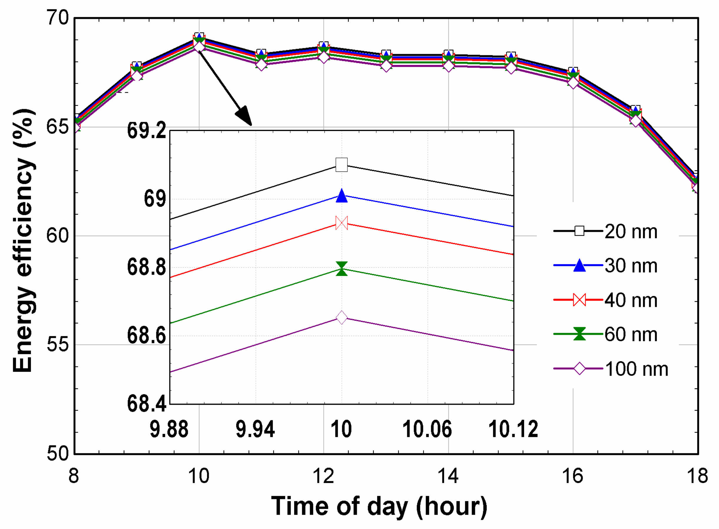
  • The maximum energy efficiency, 69.1%, was measured for the Ag-20 nm at 10 am;
  • The lowest pressure drop, 734.3 Pa, which is a net positive for the FPC system, was measured for the Ag-20 nm, while the maximum pressure drop, 1002 Pa, was measured for the Ag-60 nm at 0.08 kg/s;
  • Relative to water, the Ag-100 nm resulted in the lowest damage costs: 7.428837, 1.579411, and 4.096075 USD/kg for the CO2, SOx, and NOx, respectively;
  • The maximum pump work was measured for the Ag-60 nm, with 0.072 W.
This study focuses on how the size of nanoparticles affects how well solar flat plate collectors conduct heat transfers. The practical use of nanofluids in collector systems has been hampered by the paucity of research in this field. Our research discovered that the Ag nanofluids’ mean fluid temperature, usable heat, energy efficiency, pressure drop, pump effort, and environmental consequences are significantly influenced by the size of the nanoparticles. At ten in the morning, the maximum temperature and useable heat of the Ag-20 nm were measured, along with its highest energy efficiency. The Ag-20 nm had the lowest measured pressure loss, whereas the Ag-60 nm had the highest recorded pump work. The Ag-100 nm provided the lowest damage costs for CO2, SOx, and NOx relative to those of water in terms of environmental effects.
This study concludes that further research should be conducted on a wider range of nanoparticle sizes of both conventional and hybrid nanofluids and that the effect of nanoparticle size should be studied in both future numerical and experimental investigations. Future research should also take into account the hybrid effect of nanoparticle size and volume fraction, as well as nanoparticle size and type of the base fluid. Overall, the results of this work offer insightful information on how the size of nanoparticles affects the thermal efficiency of solar flat plate collectors and can guide further studies in this field.

Author Contributions

Conceptualization, H.A. methodology, H.A. and M.A.; software, M.A.; validation, T.R.; formal analysis, A.T. and J.J.M.; writing—review and editing, T.R. All authors have read and agreed to the published version of the manuscript.

Funding

This research received no external funding.

Institutional Review Board Statement

Not applicable.

Informed Consent Statement

Not applicable.

Data Availability Statement

No data were used.

Conflicts of Interest

The authors declare no conflict of interest.

Nomenclature

ΔPPressure drop
ηEfficiency
ApArea of aperture
CpSpecific heat capacity
EPEmission production
FCoefficient of collector efficiency
FPCFlat plate collector
FRRemoval factor
hbHeat transfer coefficient at back of collector
LeEdge thickness
mMass flow rate
QuUseful energy
SSolar irradiance
TaAmbient temperature
TpmMean plate temperature

References

  1. Wole-Osho, I.; Bamisile, O.; Adun, H.; Yusuf, I. Comparison of renewable energy potential in relation to renewable energy policy in ECOWAS countries. In Proceedings of the IEEE HONET-ICT, Nicosia, Cyprus, 13–14 October 2016; pp. 24–28. [Google Scholar]
  2. Martins, F.; Felgueiras, C.; Smitkova, M.; Caetano, N. Analysis of Fossil Fuel Energy Consumption and Environmental Impacts in European Countries. Energies 2019, 12, 964. [Google Scholar] [CrossRef] [Green Version]
  3. Ellabban, O.; Abu-rub, H.; Blaabjerg, F. Renewable energy resources : Current status, future prospects and their enabling technology. Renew. Sustain. Energy Rev. 2014, 39, 748–764. [Google Scholar] [CrossRef]
  4. Bilen, K.; Ozyurt, O.; Bakırcı, K.; Karslı, S.; Erdogan, S.; Yılmaz, M.; Comaklı, O.K. Energy production, consumption, and environmental pollution for sustainable development : A case study in Turkey. Sustain. Energy Rev. 2008, 12, 1529–1561. [Google Scholar] [CrossRef]
  5. Heinberg, R. Ur Enewable Future; Island Press: Washington, DC, USA, 2015. [Google Scholar]
  6. Kohl, W.L. Consumer country energy cooperation: The International Energy Agency and the global energy order. In Global Energy Governance: The New Rules of the Game; Global Public Policy Institute: Berlin, Germany; Brookings Institution Press: Washington, DC, USA, 2010; pp. 195–220. [Google Scholar]
  7. Gorjian, S.; Ebadi, H.; Calise, F.; Shukla, A.; Ingrao, C. A review on recent advancements in performance enhancement techniques for low-temperature solar collectors. Energy Convers. Manag. 2020, 222, 113246. [Google Scholar] [CrossRef]
  8. Hottel, B.B.; Woertz, H.C. The performance of flat-plate solar heat collectors. Trans. Am. Soc. Mech. Eng. 2002, 64, 91–103. [Google Scholar]
  9. Hottel, A.; Whillier, H. Evaluation of flat-plate solar collector performance. Trans. Conf. Use Sol. Energy 1955, 3, 19–41. [Google Scholar]
  10. Tabarhoseini, S.M.; Sheikholeslami, M.; Said, Z. Solar Energy Materials and Solar Cells Recent advances on the evacuated tube solar collector scrutinizing latest innovations in thermal performance improvement involving economic and environmental analysis. Sol. Energy Mater. Sol. Cells 2022, 241, 111733. [Google Scholar] [CrossRef]
  11. Murari, K.; Chaurasiya, R. A review on analysis and development of solar fl at plate collector. Renew. Sustain. Energy Rev. 2017, 67, 641–650. [Google Scholar] [CrossRef]
  12. Al Faris, H.; Khonkar, H. A simulation modeling for optimization of flat plate collector design in Riyadh, Saudi Arabia. Renew. Energy 2003, 28, 1325–1339. [Google Scholar] [CrossRef]
  13. Beikircher, T.; Möckl, M.; Osgyan, P.; Streib, G. Solar Energy Materials & Solar Cells Advanced solar fl at plate collectors with full area absorber, front side fi lm and rear side vacuum super insulation. Sol. Energy Mater. Sol. Cells 2015, 141, 398–406. [Google Scholar] [CrossRef]
  14. Yu, W.; Xie, H. A Review on Nanofluids: Preparation, Stability Mechanisms, and Applications. J. Nanomater. 2012, 2012, 435873. [Google Scholar] [CrossRef] [Green Version]
  15. Wang, X.; Xu, X.; Choi, S.U.S. Thermal conductivity of nanoparticle-fluid mixture. J. Thermophys. Heat Transf. 1999, 13, 474–480. [Google Scholar] [CrossRef]
  16. Babar, H.; Ali, H.M. Towards hybrid nano fluids: Preparation, thermophysical properties, applications, and challenges. J. Mol. Liq. 2019, 281, 598–633. [Google Scholar] [CrossRef]
  17. Kumar, N.; Sonawane, S.S.; Sonawane, S.H. Experimental study of thermal conductivity, heat transfer and friction factor of Al2O3 based nanofluid. Int. Commun. Heat Mass Transf. 2017, 90, 1–10. [Google Scholar] [CrossRef]
  18. Akilu, S.; Baheta, A.T.; Sharma, K.V. Experimental measurements of thermal conductivity and viscosity of ethylene glycol-based hybrid nanofluid with TiO2-CuO/C inclusions. J. Mol. Liq. 2017, 246, 396–405. [Google Scholar] [CrossRef]
  19. Babu, J.A.R.; Kumar, K.K.; Rao, S.S. State-of-art review on hybrid nanofluids. Renew. Sustain. Energy Rev. 2017, 77, 551–565. [Google Scholar] [CrossRef]
  20. Adun, H.; Kavaz, D.; Dagbasi, M.; Umar, H.; Wole-Osho, I. An experimental investigation of thermal conductivity and dynamic viscosity of Al2O3-ZnO-Fe3O4 ternary hybrid nanofluid and development of machine learning model. Powder Technol. 2021, 394, 1121–1140. [Google Scholar] [CrossRef]
  21. Sahoo, R.R. Thermo-hydraulic characteristics of radiator with various shape nanoparticle-based ternary hybrid nanofluid. Powder Technol. 2020, 370, 19–28. [Google Scholar] [CrossRef]
  22. Wole-Osho, I.; Okonkwo, E.C.; Kavaz, D.; Abbasoglu, S. An experimental investigation into the effect of particle mixture ratio on specific heat capacity and dynamic viscosity of Al2O3-ZnO hybrid nanofluids. Powder Technol. 2020, 363, 699–716. [Google Scholar] [CrossRef]
  23. Mousavi, S.M.; Esmaeilzadeh, F.; Wang, X.P. Effects of temperature and particles volume concentration on the thermophysical properties and the rheological behavior of CuO/MgO/TiO2 aqueous ternary hybrid nanofluid: Experimental investigation. J. Therm. Anal. Calorim. 2019, 137, 879–901. [Google Scholar] [CrossRef]
  24. Moravej, M.; Vahabzadeh, M.; Guan, Y.; Li, L.K.B. Enhancing the e ffi ciency of a symmetric flat-plate solar collector via the use of rutile TiO2-water nano fluids. Sustain. Energy Technol. Assess. 2020, 40, 100783. [Google Scholar] [CrossRef]
  25. Khetib, Y.; Abo-dief, H.M.; Alanazi, A.K.; Sajadi, S.M. Effect of nanoparticles shape on turbulent nanofluids flow within a solar collector by using hexagonal cross-section tubes. Sustain. Energy Technol. Assess. 2022, 51, 101843. [Google Scholar] [CrossRef]
  26. Jamal-abad, M.T.; Zamzamian, A.; Imani, E.; Mansouri, M. Experimental Study of the Performance of a Flat-Plate Collector Using Cu—Water Nanofluid. J. Thermophys. Heat Transf. 2013, 27, 756–760. [Google Scholar] [CrossRef]
  27. Ahmed, M.; Gr, G. Experimental study on the performance of a fl at-plate collector using WO3/Water nano fluids. Energy 2017, 141, 2436–2444. [Google Scholar] [CrossRef]
  28. Science, E. Potential of size reduction of flat-plate solar collectors when applying MWCNT nanofluid. IOP Conf. Ser. Earth Environ. Sci. 2013, 16, 012004. [Google Scholar] [CrossRef]
  29. Khetib, Y.; Alzaed, A.; Tahmasebi, A.; Sharifpur, M.; Cheraghian, G. Influence of using innovative turbulators on the exergy and energy efficacy of flat plate solar collector with DWCNTs-TiO2/water nanofluid. Sustain. Energy Technol. Assess. 2022, 51, 101855. [Google Scholar] [CrossRef]
  30. Abu-hamdeh, N.H.; Alazwari, M.A.; Salilih, E.M.; Sajadi, S.M.; Karimipour, A. Improve the efficiency and heat transfer rate’ trend prediction of a flat-plate solar collector via a solar energy installation by examine the Titanium Dioxide/Silicon Dioxide-water nanofluid. Sustain. Energy Technol. Assess. 2021, 48, 101623. [Google Scholar] [CrossRef]
  31. Ali, S.A.; Naser, K.A. Improving performance of flat plate solar collector using nanofluid water/zinc oxide. J. Cent. South Univ. 2021, 28, 3391–3403. [Google Scholar]
  32. Alawi, O.A.; Kamar, H.M.; Mallah, A.R.; Mohammed, H.A.; Sabrudin, M.A.S.; Newaz, K.M.S.; Najafi, G.; Yaseen, Z.M. Experimental and Theoretical Analysis of Energy Efficiency in a Flat Plate Solar Collector Using Monolayer Graphene Nanofluids. Sustainability 2021, 13, 5416. [Google Scholar] [CrossRef]
  33. Alawi, O.A.; Mohamed, H.; Mallah, A.R.; Kazi, S.N.; Azwadi, N.; Sidik, C. Thermal efficiency of a flat-plate solar collector filled with Pentaethylene Glycol-Treated Graphene Nanoplatelets : An experimental analysis. Sol. Energy 2019, 191, 360–370. [Google Scholar] [CrossRef]
  34. Alawi, O.A.; Kamar, H.M.; Mallah, A.R.; Mohammed, H.A.; Sabrudin, M.A.S.; Hussein, O.A.; Kazi, S.N.; Najafi, G. Graphene Nanoplatelets Suspended in Different Basefluids Based Solar Collector: An Experimental and Analytical Study. Processes 2021, 9, 302. [Google Scholar] [CrossRef]
  35. Stalin, P.M.J.; Arjunan, T.V.; Matheswaran, M.M.; Sadanandam, N. Experimental and theoretical investigation on the effects of lower concentration CeO2/water nanofluid in flat-plate solar collector. J. Therm. Anal. Calorim. 2019, 135, 29–44. [Google Scholar] [CrossRef]
  36. Yousefi, T.; Shojaeizadeh, E.; Veysi, F.; Zinadini, S. An experimental investigation on the effect of pH variation of MWCNT-H 2O nanofluid on the efficiency of a flat-plate solar collector. Sol. Energy 2012, 86, 771–779. [Google Scholar] [CrossRef]
  37. Youse, T.; Veysi, F.; Shojaeizadeh, E.; Zinadini, S. An experimental investigation on the effect of Al2O3-H2O nanofluid on the efficiency of flat-plate solar collectors. Renew. Energy 2012, 39, 293–298. [Google Scholar] [CrossRef]
  38. Akram, N.; Montazer, E.; Kazi, S.N.; Soudagar, M.E.M.; Ahmed, W.; Zubir, M.N.M.; Afzal, A.; Muhammad, M.R.; Ali, H.M.; Márquez, F.P.G.; et al. Experimental investigations of the performance of a flat-plate solar collector using carbon and metal oxides based nano fluids. Energy 2021, 227, 120452. [Google Scholar] [CrossRef]
  39. Chon, C.H.; Kihm, K.D.; Lee, S.P.; Choi, S.U.; Chon, C.H.; Kihm, K.D. Empirical correlation finding the role of temperature and particle size for nanofluid (Al2O3) thermal conductivity enhancement. Appl. Phys. Lett. 2005, 87, 153107. [Google Scholar] [CrossRef]
  40. Teng, T.; Hung, Y.; Teng, T.; Mo, H.; Hsu, H. The effect of alumina/water nano fl uid particle size on thermal conductivity. Appl. Therm. Eng. 2010, 30, 2213–2218. [Google Scholar] [CrossRef]
  41. Chopkar, I.; Sudarshan, S.; Das, P.K.; Manna, I. Effect of particle size on thermal conductivity of nanofluid. Metall. Mater. Trans. A Phys. Metall. Mater. Sci. 2008, 39, 1535–1542. [Google Scholar] [CrossRef]
  42. Beck, M.P.; Yuan, Æ.Y.; Warrier, P.; Teja, Æ.A.S. The effect of particle size on the thermal conductivity of alumina nanofluids. 2009, 2009, 1129–1136. J. Nanoparticle Res. 2009, 2009, 1129–1136. [Google Scholar] [CrossRef]
  43. Warrier, P.; Teja, A. Effect of particle size on the thermal conductivity of nanofluids containing metallic nanoparticles. Nanoscale Res. Lett. 2011, 6, 247. [Google Scholar] [CrossRef] [Green Version]
  44. Nguyen, C.T.; Desgranges, F.; Roy, G.; Galanis, N.; Maré, T.; Boucher, E.; Mintsa, H.A. Temperature and particle-size dependent viscosity data for water-based nanofluids—Hysteresis phenomenon. Int. J. Heat Fluid Flow 2007, 28, 1492–1506. [Google Scholar] [CrossRef]
  45. Lu, W.-Q.; Fan, Q.-M. Fan Study for the particle’s scale effect on some thermophysical properties of nanofluids by a simplified molecular dynamics method. Eng. Anal. Bound. Elem. 2008, 32, 282–289. [Google Scholar] [CrossRef]
  46. Dhairiyasamy, R.; Saleh, B.; Govindasamy, M.; Ayman, A.; Afzal, A.; Abdelrhman, Y. Effect of particle size on thermophysical and heat transfer properties of Ag nanofluid in a radiator—An experimental investigation. Inorg. Nano-Metal Chem. 2021, 53, 78–92. [Google Scholar] [CrossRef]
  47. Mustafa, J.; Alqaed, S.; Sharifpur, M. Evaluation of energy efficiency, visualized energy, and production of environmental pollutants of a solar flat plate collector containing hybrid nanofluid. Sustain. Energy Technol. Assess. 2022, 53, 102399. [Google Scholar] [CrossRef]
  48. Joseph, P.M.; Arjunan, S.T.V.; Dolli, M.M.M.H. Energy, economic and environmental investigation of a flat plate solar collector with CeO2/water nanofluid. J. Therm. Anal. Calorim. 2020, 139, 3219–3233. [Google Scholar] [CrossRef]
  49. Fudholi, A.; Sopian, K. A review of solar air flat plate collector for drying application. Renew. Sustain. Energy Rev. 2019, 102, 333–345. [Google Scholar] [CrossRef]
  50. Elminir, H.K.; Ghitas, A.E.; El-hussainy, F.; Hamid, R. Optimum solar flat-plate collector slope: Case study for Helwan, Egypt. Energy Convers. Manag. 2006, 47, 624–637. [Google Scholar] [CrossRef]
  51. Verma, S.K.; Tiwari, A.K.; Chauhan, D.S. Experimental evaluation of flat plate solar collector using nanofluids. Energy Convers. Manag. 2017, 134, 103–115. [Google Scholar] [CrossRef]
  52. Duffie, N.; Beckman, J.A.; Blair, W.A. Solar Engineering of Thermal Processes, Photovoltaics and Wind; John Wiley & Sons: Hoboken, NJ, USA, 2020. [Google Scholar]
  53. Dominguez, J. Solar Energy Engineering Processes and Systems, 2nd ed.; Elsevier Inc.: Amsterdam, The Netherlands, 2017. [Google Scholar]
  54. Sarsam, W.S.; Kazi, S.N.; Badarudin, A. Thermal performance of a flat-plate solar collector using aqueous colloidal dispersions of multi-walled carbon nanotubes with different outside diameters. Exp. Heat Transf. 2022, 35, 258–281. [Google Scholar] [CrossRef]
  55. Amin, T.E.; Roghayeh, G.; Fatemeh, R.; Fatollah, P. Evaluation of nanoparticle shape effect on a nanofluid based flat-plate solar collector efficiency. Energy Explor. Exploit. 2015, 33, 659–676. [Google Scholar] [CrossRef] [Green Version]
  56. Dobriyal, R.; Negi, P.; Sengar, N.; Singh, D.B. Materials Today : Proceedings A brief review on solar flat plate collector by incorporating the effect of nanofluid. Mater. Today Proc. 2020, 21, 1653–1658. [Google Scholar] [CrossRef]
  57. Said, Z.; Sabiha, M.A.; Saidur, R.; Hepbasli, A.; Rahim, N.A.; Mekhilef, S.; Ward, T.A. Performance enhancement of a Flat Plate Solar collector using Titanium dioxide nanofluid and Polyethylene Glycol dispersant. J. Clean. Prod. 2015, 92, 343–353. [Google Scholar] [CrossRef]
  58. ADUN, H.; Mukhtar, M.; Adedeji, M.; Agwa, T.; Ibrahim, K.H.; Bamisile, O.; Dagbasi, M. Synthesis and Application of Ternary Nanofluid for Photovoltaic-Thermal System: Comparative Analysis of Energy and Exergy Performance with Single and Hybrid Nanofluids. Energies 2021, 14, 4434. [Google Scholar] [CrossRef]
  59. Suzuki, A. General theory of exergy-balance analysis and application to solar collectors. Energy 1988, 13, 153–160. [Google Scholar] [CrossRef]
  60. Farahat, S.; Sarhaddi, F.; Ajam, H. Exergetic optimization of flat plate solar collectors. Renew. Energy 2009, 34, 1169–1174. [Google Scholar] [CrossRef]
  61. Kotas, T.J. The Exergy Analysis Method of Thermal Plant Analysis; Krieger: Melbourne, Australia, 1995. [Google Scholar]
  62. Ardente, F.; Beccali, G.; Cellura, M.; Lo Brano, V. Life cycle assessment of a solar thermal collector. Renew. Energy 2005, 30, 1031–1054. [Google Scholar] [CrossRef]
  63. Adun, H.; Adedeji, M.; Ruwa, T.; Senol, M.; Kavaz, D. Energy, exergy, economic, environmental (4E) approach to assessing the performance of a photovoltaic-thermal system using a novel ternary nanofluid. Sustain. Energy Technol. Assess. 2022, 50, 101804. [Google Scholar] [CrossRef]
  64. Steen, M. Greenhouse Gas Emissions from Fossil Fuel Fired Power Generation Systems; Institute for Advanced Materials, Joint Research Centre, European Commission: Ispra, VA, Italy, 2000. [Google Scholar]
  65. Akhtar, N.; Mullick, S.C. International Journal of Heat and Mass Transfer Effect of absorption of solar radiation in glass-cover (s) on heat transfer coefficients in upward heat flow in single and double glazed flat-plate collectors. Int. J. Heat Mass Transf. 2012, 55, 125–132. [Google Scholar] [CrossRef]
  66. Zayed, M.E.; Zhao, J.; Du, Y.; Kabeel, A.E.; Shalaby, S.M. Factors a ff ecting the thermal performance of the fl at plate solar collector using nano fluids : A review. Sol. Energy 2019, 182, 382–396. [Google Scholar] [CrossRef]
  67. Timofeeva, E.V.; Smith, D.S.; Yu, W.; France, D.M.; Singh, D.; Routbort, J.L. Particle size and interfacial effects on thermo-physical and heat transfer characteristics of water-based α-SiC nanofluids. Nanotechnology 2010, 21, 215703. [Google Scholar] [CrossRef]
  68. Pak, B.C.; Cho, Y.I. Hydrodynamic and heat transfer study of dispersed fluids with submicron metallic oxide particles transfer study of dispersed fluids with submicron metallic oxide. Exp. Heat Transf. 1998, 11, 151–170. [Google Scholar] [CrossRef]
  69. Torii, W.J.; Yang, S. Heat transfer augmentation of aqueous suspensions of nanodiamonds in turbulent pipe flow. J. Heat Transfer 2009, 131, 043203. [Google Scholar] [CrossRef]
  70. Naveen, N.S.; Kishore, P.S.; Bargar, H.E.; Das, D.K. Convective Heat Transfer and Fluid Dynamic Characteristics of SiO2 Ethylene Glycol/Water Nanofluid Convective Heat Transfer and Fluid Dynamic Characteristics of SiO2—Ethylene Glycol/Water Nanofluid. Heat Transf. Eng. 2010, 29, 1027–1035. [Google Scholar] [CrossRef]
  71. Xuan, Y.; Li, Q. Investigation on convective heat transfer and flow features of nanofluids. J. Heat Transfer 2003, 125, 151–155. [Google Scholar] [CrossRef] [Green Version]
  72. He, Y.; Jin, Y.; Chen, H.; Ding, Y.; Cang, D.; Lu, H. Heat transfer and flow behaviour of aqueous suspensions of TiO2 nanoparticles (nanofluids) flowing upward through a vertical pipe. Int. J. Heat Mass Transf. 2007, 50, 2272–2281. [Google Scholar] [CrossRef]
  73. Kanti, P.; Sharma, K.V.; Raja Sekhar, Y. Influence of particle size on thermal conductivity and dynamic viscosity of water-based Indian coal fly ash nanofluid. Heat Transfer 2022, 51, 413–433. [Google Scholar] [CrossRef]
  74. Alim, M.A.; Abdin, Z.; Saidur, R.; Hepbasli, A.; Khairul, M.A.; Rahim, N.A. Analyses of entropy generation and pressure drop for a conventional flat plate solar collector using different types of metal oxide nanofluids. Energy Build. 2013, 66, 289–296. [Google Scholar] [CrossRef]
  75. Majdi, H.; Abed, A.M. Effect of nanofluids on the performance of corrugated channel within out-of-phase arrangement. Int. Int. J. Sci. Technol. Res. 2014, 3, 220–229. [Google Scholar]
  76. Asif, M.; Dhiman, A.K. Effect of alumina nanoparticle shape in a triangular porous array of heated periodic pin-fins. Korean J. Chem. Eng. 2021, 38, 704–715. [Google Scholar] [CrossRef]
Figure 1. Effects of nanoparticles on thermophysical properties.
Sustainability 15 05271 g001
Figure 2. Flat plate collector.
Sustainability 15 05271 g002
Figure 3. Variation in incident solar radiation and ambient temperature.
Sustainability 15 05271 g003
Figure 4. Mean fluid temperature of FPC across time of the day.
Sustainability 15 05271 g004
Figure 5. Fluid outlet temperature at considered NPS.
Sustainability 15 05271 g005
Figure 6. Useful heat of nanofluid across the day.
Sustainability 15 05271 g006
Figure 7. Energy efficiency of nanofluid at different nanoparticle sizes.
Sustainability 15 05271 g007
Figure 8. Exergy efficiency of FPC across the time of the day.
Sustainability 15 05271 g008
Figure 9. Pressure drop across (a) varying mass flow rates; and (b) times of day.
Sustainability 15 05271 g009
Figure 10. Pump work of the FPC (a) varying mass flow rates; and (b) times of day.
Sustainability 15 05271 g010
Table 1. Experimental and numerical analysis of nanofluid-based flat plate collector.
ReferenceNanofluid UsedNanoparticle SizeVolume ConcentrationResult Obtained
Omer et al. [32]Covalently functionalized graphene (Gr)289.6 nm0.025%-wt., 0.05%-wt., 0.075%-wt.The optimum removal factor determined was 11.67%, using a volume concentration of 0.1 wt%.
Omer et al. [33]Glycol-treated graphene nanoplatelets-0.025, 0.05, 0.075, and 0.1 wt%When the flow rate was held constant at 0.025 kg/s and the weight concentration was 0.1 wt%, the largest improvement in solar collector thermal performance was 13.3%
Omer et al. [34]Graphene/EG; Graphene/water; Graphene/DW: EG (70:30), DW: EG (50:50)-0.025, 0.05, 0.075, and 0.1 wt%The maximum heat gain was measured for the nanofluid with a DW:EG ratio of (70:30) for all volume concentrations
Stalin et al. [35]CeO2/water25 nm0.01%78.2% maximum efficiency and 21.5% enhancement against water
Yousefi et al. [36]MWCNT–H2O-0.2 wt.%According to the experimental findings, the greater the discrepancies between the pH of the nanofluid and the pH of the isoelectric point, the greater the increase in collector efficiency.
Tooraj et al. [37]Al2O3/water15 nm0.2% and 0.4%The maximum efficiency enhancement was 28.3% against water, with volume concentration of 0.2%.
Naveed et al. [38]f-GNPs, SiO2, and ZnOZnO-50 nm
SiO2-10–20 nm
0.025 wt.%, 0.05 wt.%, 0.075 wt.% and 0.1 wt.%The results show that compared to DI water, all nanofluids enhanced the thermal performance of FPSCs.
Table 3. Released pollutants of fuel power plants burning oil [64].
PollutantsValues
Sulphur oxide9 g per kWh
Nitrogen oxide2 g per kWh
Carbon dioxide644 g per kWh
Particles released to the air0.7 g per kWh
Table 4. Model validation of experimental and modelled analysis of FPC using WO3/water.
ReferenceVolume Fraction %Mass Flux Rate (kg/s.m2) Experimental   Result   F R τ α Modelled   Result   F R τ α Error Percentage
Mahmoud et al. [27]0.01670.01560.63870.63770.1568
0.01830.65390.65350.0612
0.01950.66020.65990.0454
0.03330.01560.65850.65820.0455
0.01830.68350.68210.2052
0.01950.69660.69600.0862
Table 5. Model validation of experimental and modelled analysis of FPC using graphene/water.
ReferenceMass Flow Rate (kg/min)Volume Concentration Experimental   Result   F R τ α Modelled   Result   F R τ α Error Percentage
Alawi et al. [33]0.50.0250.7060.7050.1418
0.050.7210.7210
0.0750.7280.7250.4138
0.10.7350.7300.6849
10.0250.7220.7190.4172
0.050.7370.7350.2721
0.0750.7450.7420.4043
0.10.7520.7500.2667
Table 6. Model validation of experimental and modelled analyses of outlet temperature (40 °C inlet temperature).
ReferenceMass Flow Rate (kg/min)Volume ConcentrationExperimental Result (Outlet Temp)Modelled Result (Outlet Temperature)Error Percentage
[4]0.5149.649.70.2
350.451.20.39
551.651.50.19
Table 7. Embodied energy emissions from the different nanoparticle-size-based solar collectors.
Water20 nm30 nm40 nm60 nm100 nm
Size reduction (%) 16.8117.0717.3517.7518.30
Embodied energy (MJ)1183984.14816.15674.54554.81453.28
Emission (kg)
Carbon dioxide (CO2)718.081597.372495.400409.448336.771275.142
Sulphur oxides (SOx)0.36670.30510.25300.20910.17200.1405
Nitrogen oxides (NOx)0.62700.52160.43260.35750.29410.2402
Table 8. Yearly damage costs from the different nanoparticle-size-based solar collectors.
Cost (USD/kg)Water20 nm30 nm40 nm60 nm100 nm
Carbon dioxide (CO2)0.02719.3881916.1290313.3758111.05519.0928227.428837
Sulphur oxides (SOx)11.244.1220453.4291332.8437762.3503851.933191.579411
Nitrogen oxides (NOx)17.0510.690188.8931617.3750976.0955115.013574.096075
Total (USD) 34.2004128.4513323.5946819.50116.0395813.10432
Disclaimer/Publisher’s Note: The statements, opinions and data contained in all publications are solely those of the individual author(s) and contributor(s) and not of MDPI and/or the editor(s). MDPI and/or the editor(s) disclaim responsibility for any injury to people or property resulting from any ideas, methods, instructions or products referred to in the content.

