1. Introduction
Rock mass is a complex medium made up with solid and pore fracture, and the pore fracture is the storage place and movement channel of the fluids inside. Engineering rock mass bears vertical and horizontal stress, as well as pore pressure, which leads to the balance of the rock mass. When coal, methane and underwater are exploited out, there is a certain form of deformation during the excavation. During the process of coal mining, with the coal face going on, the direct roof will collapse and the overlying strata will move and break, which form the mining fissure zone. This may also result in the phenomenon of stress redistribution.
The ground pressure and the strata control have been extensively studied in the literature. For instance, Qian [
1,
2] proposes an important theory for the movement of strata, which establishes the criteria to identify the key strata. They also provide insights into the law of deformation, abscission layer and breaking with respect to the key strata. Yuan [
3,
4] proposes key techniques for the simultaneous extraction of the coal and gas, the support of an easy abscission layer and the geology protection under complex geological conditions. Based on the analogy simulation tests on the protective layer, Lin [
5,
6] proposes the dynamic evolution law of overlying strata pressure relief, instability, crack initiation, crack extension and fracture atrophy. By utilizing the numerical simulation technique, Tu [
7] investigates the law of stress distribution of overlying strata and the deformation law of protected layer. It is reported that the expansion of the protected layer will enhance its air permeability.
Taking fractured rock mass as the research object, the previous research results on the failure mechanism under different rock mass sizes were reviewed. With the help of advanced equipment, such as high-resolution digital cameras, scanning electron microscopy and CT scanners, model material tests and mechanics experiments on the solid rock material were carried out to study the effects of different conditions, such as rock bridge inclination, fissure spacing, fracture fissure length, fissure number, fissure dip angle and fissure penetration degree [
8,
9,
10]. A set of experimental techniques for roadway excavation under jointed surrounding rock included a mixed pouring–bricking method and a roadway excavation device, which can reproduce the structural characteristics of the prototype and replicate the excavation conditions of the roadway [
11,
12,
13]. Some methods of machine learning and a safety evaluation model are used to explain the dynamic propagation process of fracture [
14,
15]. Although great progress has been made in the study of fractures, it has not yet been directly applied in the field test. Bored imaging theory can effectively solve the above deficiencies.
In order to study the breaking law of overlying strata, a special methane roadway was deployed at the floor of the E group coal seam. Meanwhile, some holes were drilled, and a Bored Imaging machine was used to scan the overlying strata of the F coal groups influenced by the excavation. Then, the development condition of the fissure zone was calculated, and the characteristic of the overlying strata evolution law of the mining face was investigated. Together with the breaking theory of strata, we study the intensity factor of fractured rock mass, and hence verify whether the fissure can develop and form the macroscopic fractured zone.
2. Engineering Situation
The F coal mine group is at the middle and lower part of the Shanxi group. The evaluation height of the working face of F15 ranges from −560 m to −660 m, and the effective strike length of the working face is 1600 m, with a mining length of 195 m and a mining height of 2.0 m, and 840,000 tons of coal will be mined. The inner section of the working face only has an F15 coal mine, the thickness of which ranges from 1.6 m to 2.3 m. The outer section is the combination of an F15 and F16 coal seam, where the coal seam is relatively stable and the structure is simple. The east dip angle of the coal seam is relatively small, which is usually 10°. The angle in the middle and upper part is slightly larger, ranging from 25° to 30°. The method used was strike retreating comprehensive mechanized l mining, and the management method for the roof is the all-collapse method. The borehole diagram of F15 is shown in
Figure 1.
3. Bored Imaging Technology
3.1. Bored Imaging System
Advanced DSP image collection and treatment techniques are used in a highly integrated system. The probe can take panoramic pictures, and the image of the section can be produced immediately. The image is clear, the depth can be corrected automatically and the images of all holes can be obtained from all directions.
This equipment can not only observe the structure in the hole, but also produce plane graph and 3D prism display. Therefore, the structure of the hole can be quantitatively analyzed by the image produced, and the attitude of the coal and thickness can be detected effectively. By analyzing different images of the hole at different times, the development of surrounding rock joints and faults can be detected. Therefore, underground disasters, such as roadway instability, can be predicted. The equipment can provide real and effective data for the design of the support and protection of the surrounding rock, and hence, improve the safety conditions of underground coal mining. The bored imaging technique used in this paper is the state-of-the-art hole imaging system. The schematic diagram of the system is shown in
Figure 2. It includes a mainframe, synchronous shaft and bore bit.
3.2. Actual Measurements and Results Analysis of Fractured Holes
To monitor the development condition of the overlying rock’s fissure zone, some holes for observation were drilled [
16,
17,
18]. Then, the equipment was used to monitor the structure and fissure development characteristics of the overlying rock, and further study was conducted on the basis of the data collected by the equipment. Based on the local condition, the holes were drilled in the methane roadway of the E group, and the working face of the stope was beneath the methane lane. According to the local condition, 12 holes were drilled, and the parameters of the holes drilled are shown in
Table 1.
The depth of the hole is designed to be 150 m. Some water-flowing fractured zones were encountered during the process of drilling the overlying rock. During the process, the hole started to lose water, and the drill ended when no water returned. Consequently, the end position of the hole can be regarded as the height of the overlying rock fissure zone. The layout conditions of the holes are shown in
Figure 3. Six boreholes were monitored. The inclination was 20° for borehole No. 10, 30° for No. 11, 40° for No. 6, 45° for No. 12, −20° for No. 9 and −35° for No. 8. The sign represents the direction, defining the angle with the vertical stress, and is positive in the counterclockwise direction and negative in the clockwise direction. The methane roadway was in coal seam E, and beneath was coal seam F15.
Taking 1# as an example, there is no need of angle conversion because it is vertical. The measured altitude at the start point of the hole was −560 m, and that of the end point was −620 m. When experimenting with bored imaging on 1#, the working face of the F coal seam was directly beneath the methane roadway. The expansion columnar image received from bored imaging is shown in
Figure 4. Ten cracks were observed and signed in red marks. The results are shown in
Table 2. With the increasing depth of the hole, the bottom of the hole was closer to the mining area. Meanwhile, the fissure became closer, and the angle of the fissure grows larger. Finally, the fissure zone was developed. The more broken the rock was, the larger the width of the fissure. The distribution of the fissure influenced by mining is related to the characteristic and integrity of the strata. The fissure in the hard strata is relatively larger, and the fissures inside usually have a large angle; soft strata has relatively more fissures, and the fissures inside are crisscrossed. When it is closer to the broken zone of the coal seam, the fissures inside the strata are mainly made up with horizontal fissures, and the abscission layer appears.
Figure 5 shows four kinds of typical fracture shapes after propagation. Four kinds of typical fracture include bedding, horizontal fracture, vertical fracture and fracture zone. The upper part of the rock mass is mainly composed of primary fractures. The downward part has the trend of transforming from horizontal fractures to vertical fractures. The fracture zone appeared near the coal seam.
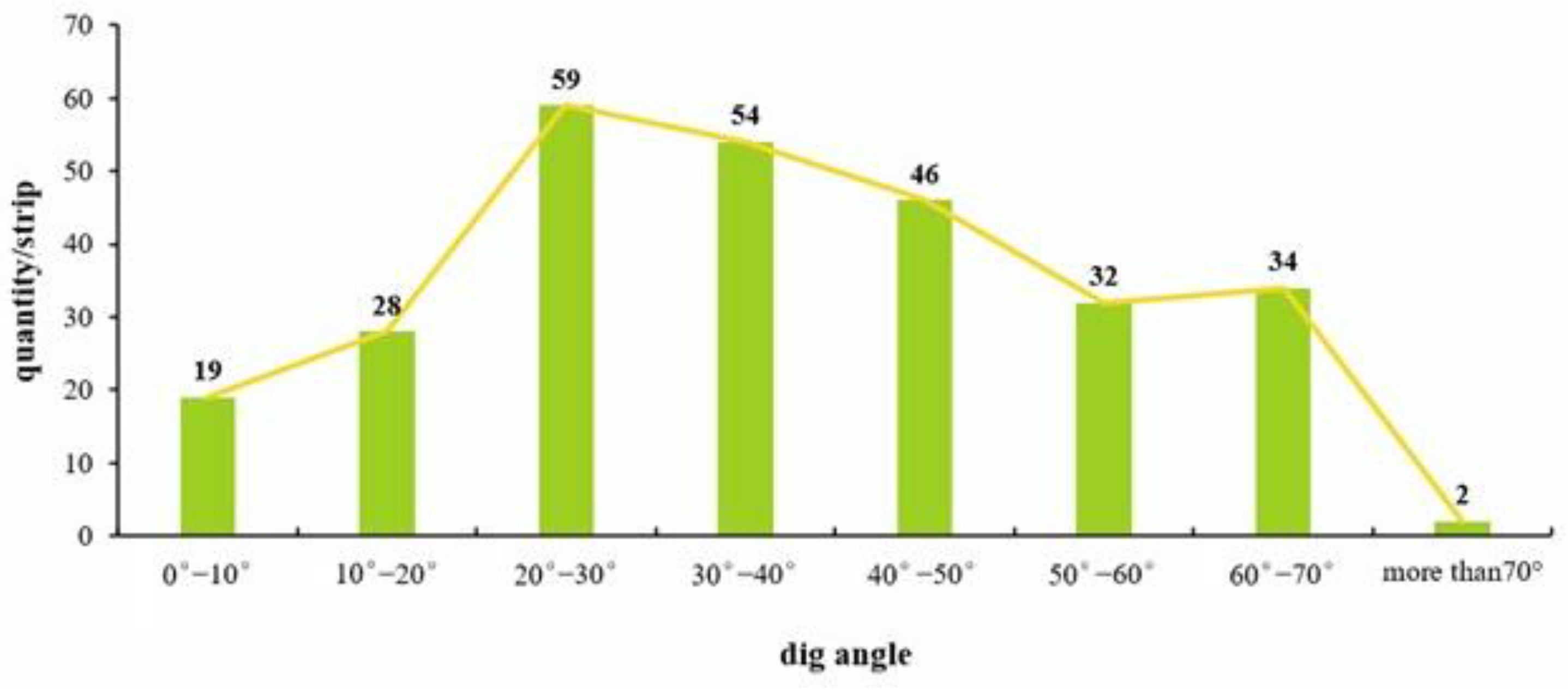
The borehole imaging data acquisition work was carried out for the drill hole from 15 August to 15 September. The original fractures of geological coring and the impact of mining conditions were analyzed. The geological loggings were carried out for the drilling core to record the location, occurrence and other information relating to the original fractures upon the completion of drilling. In the whole observation section, 1455 fractures were counted by using the method of combining geological coring with borehole television. In addition, 1208 pieces of cracks nearly did not expand and were less affected by mining. We also defined the main crack with its detailed growth trend. Excluding the influence of primary fractures, the statistical analysis of 274 main fractures with obvious development shows that there are 47 fractures with a dip angle of less than 20°, accounting for about 17%, mostly appearing at the depth of 0 to 50 m. The minimum dip angle of the cracks is 8°. There are 159 cracks with the dip angle between 20° and 50°, accounting for about 58%. The number of cracks in this part is the largest, and most of them are in the area of 50–110 m, which is the transition area from transverse cracks to oblique cracks. There are 68 cracks with the dip angle greater than 50°, accounting for about 25%. The cracks in this part are mainly concentrated below 110 m. Among them, there are two cracks with inclination angles greater than 70°, which are 70.13° and 70.39°, respectively.
Figure 6 shows the statistics of the number of typical cracks. Therefore, it can be inferred that the initial crack initiation angle is about 8° and the final crack propagation angle is 70.4°.
3.3. Analysis on the Theory of Broken Strata
In geotechnical engineering, to evaluate whether the fissures inside the strata can turn to macroscopic broken zone under external force, the stress intensity factor should be considered and the rules for broken should be used together [
19].
Fractured rock is beard with complex stress. The maximum principal stress is σ
1. Taken a fissure with length of 2a in an infinite plane as an example, the angle between the fissure and minimum principal stress(σ
3) is φ, the force condition of the fissure is shown in
Figure 7.
The tangential stress
and normal stress
in the fissure surface are:
In the equation,
is the shearing transferring coefficient and
is the compression transferring coefficient [
20].
The slide driving force in the fissure surface is:
In the equation, refers to the coefficient of the sliding friction.
Due to the existence of a pre-existing fissure, the top of the fissure appeared to be singular. The angle between the top determined by the slide driving force and the pre-existing fissure is
, where the tangential stress is defined as
.
According to Cotterell and Rice’s suggestion [
21,
22], the intensity factor of tiny fissure I on top of the fissure is shown in the following equation:
where
is the stress strength influence coefficient of the fissure.
The place where the dislocation most likely occurs, and is caused by shear stress, is the direction where the maximum efficient shear stress exits, and it can be derived from Equation (6):
Further, the following equation is derived:
when
= 1, equals
, the force to the fissure is at its limit position, indicating that the fissure only bears tensile stress, and the strata is most likely to break at this moment. Then, we have the following equation:
The biggest angle
can be obtained from the derivation of nine, and the equation is:
3.4. Big Data Analysis for Crack Propagation Angle
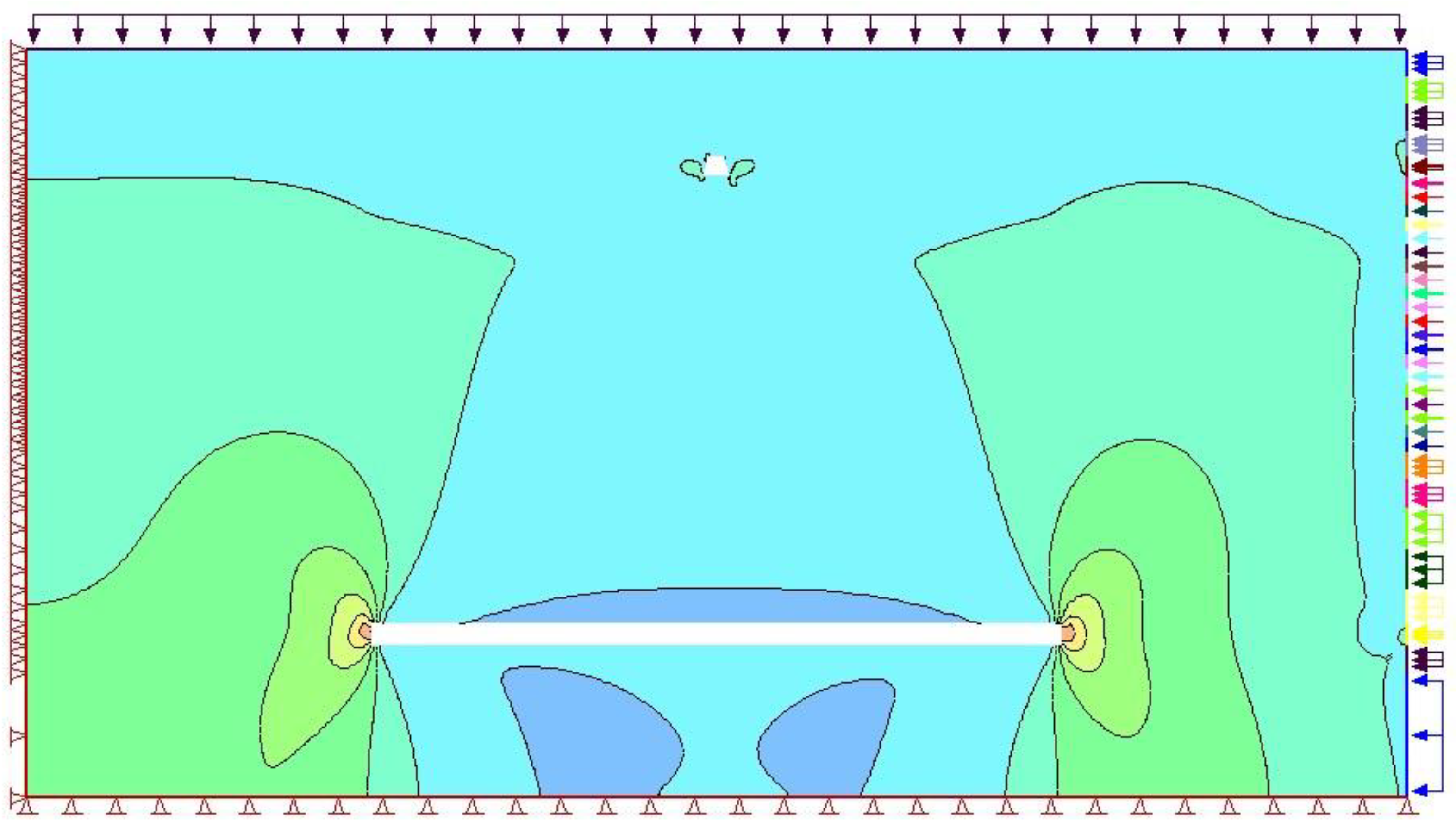
The development law of the fissure under the influence of mining can be analyzed based on theoretical analysis and the initial azimuth of the pre-existing fissure. The numerical simulation is used to analyze the distribution of the stress and plastic zone under mining conditions, and the stress value is used in the theoretical formula to calculate the crack propagation angle. To simplify the calculation, the middle stress
is ignored, and the layer with an altitude of −514 m (−785 m) is considered as the top (bottom) layer of the model. According to the stress data, the upper surface is loaded with 17.48 MPa of vertical stress, and the direction of the stress is downward; on the right of the model, trapezoidal load ranging from 31.43 MPa to 34.32 MPa is loaded on the model, and the stress direction is horizontal leftward. The left boundary of the model is horizontally fixed, and the bottom boundary of the model is vertically fixed.
Table 3 shows the current stress of different drilling depths.
Figure 8 illustrates the stress contours during drilling, and
Figure 9 shows the stress contours after excavation.
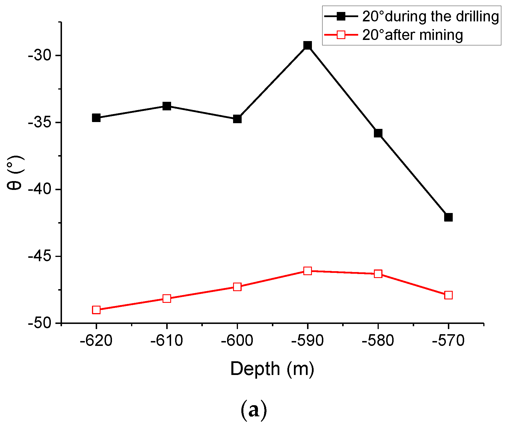
The limit condition, when the rock mass only bears tensile stress and the inclination is 20°, 30°, 40°, 45°, −35° or −20°, represents the maximum expansion angle at different depths. The results are shown in
Table 4.
Figure 10 shows the maximum angle curve with different azimuth during drilling, and the maximum angle curve after excavation. All curves are in good agreement. The boundary between the rock stratum and the coal seam is −590 m. The fracture at −590 m is different from that seen at other depths, indicating that the formation has a certain influence on the fracture propagation angle. Positive and negative signs represent the expanding direction of the fissure. The expansion of the fissure began with the top of the fissure, and the expansion tended to parallel the maximum primary stress. As the mining went on, the stress field redistributed. As the difference of primary stress increased, so did the maximum angle. When the initial azimuth was 45°, the expansion of the fissure had nothing to do with the maximum and minimum primary stress, and the largest angle of the fissure was 70.54°. Because mining fissure is in the dynamic process, when the expansion angle was relatively small, the fissure was in an unstable condition. As the stress condition changed, the expansion of the fissure continued. When the expansion angle was relatively large, indicating when the initial azimuth reached 45°, the expansion angle of the fissure could reach 70.54°. As for the inclination of the borehole as a negative value, the opposite direction of the fissure expansion was considered, and the results showed that the expansion of the fissure had the tendency to parallel the maximum primary stress.
4. Discussion
Drill holes are arranged in the upper part of the coal seam to observe the fracture development trend. If the depth of the borehole is 40 to 50 m below and located in the roof of the coal seam, the primary crack is observed at a certain initial angle. With the development of the mining process, the secondary crack tends to be the same fixed angle. It is indicated that this part is the fracture zone. And the fracture observed at the lower part of the borehole is a mining fracture, which is easy to connect with each other and form a horizontal separation layer. If the shallow part of the borehole is 10 m to 20 m, it can be seen from the previous text that this part is obviously affected by the change of ground stress. Generally, the fracture angle is not large, and this part of the fracture is considered a primary fracture. Once there is mining impact, it will expand into a large-angle fracture, before finally forming a new fracture zone. Therefore, the height of the fracture zone can be determined by observing the fracture angle, and it can provide an important basis for the simultaneous extraction of coal and gas.
5. Conclusions
By taking advantage of bored imaging technology, we analyze the evolution and distribution characteristics of the fissure field and then form the following important conclusions according to the fracture theory-based calculation:
The mining fissure distribution of the strata not only relates to the characteristics of the strata, but also relates to the integrity of the strata. The fissure in the hard strata is relatively larger, and the fissures inside are mainly of a large angle. On the other hand, the soft strata have relatively more fissures, and the fissures inside are crisscrossed.
Comparing the results of local observation and analysis on fissure strata using fracture theory, the largest expansion angle of the fissure is 70.54°, which is inconsistent with the phenomenon that the amount of fissure with an angle more than 70° is relatively small.
Once there is any mining activity on the original fissure with a small angle, which is located in the shallow layer, the influence will be extended to other areas. Meanwhile, the deep mining angle will extend and move toward the same direction. This has a high probability of producing the abscission layer and eventually leading to the breaking area. Therefore, the height of the fissure zone can be judged by the observation of the fissure angle, and it can provide an important basis for the simultaneous extraction of coal and gas.
This paper investigates the problem based on the drill hole, and does not consider the fracture law of the whole overlying strata on soft rock ring in the drilling area. As a possible future work, drill holes can be arranged at the entire range of the soft rock ring, and the expansion angle of fissure at the entire breaking area with a different drilling angle can be studied using bored imaging technique. In this way, the fracture law of the strata will be further studied, which can be better applied to engineering practice.
Author Contributions
Methodology, X.Z.; Software, M.W.; Formal analysis, X.Z.; Investigation, D.F.; Data curation, D.F.; Supervision, J.W. All authors have read and agreed to the published version of the manuscript.
Funding
This paper is funded by the Science and Technology Project of Hebei Education Department (Grant Number: QN2021128) and Key Laboratory of Large Structure Health Monitoring and Control, Shijiazhuang, 050043 (Grant Number: KLLSHMC2113).
Institutional Review Board Statement
Not applicable.
Informed Consent Statement
Not applicable.
Data Availability Statement
All datasets generated for this study are included in this paper.
Conflicts of Interest
The authors declare no conflict of interest.
References
- Qian, M.G.; Xu, J.L. Study on the “O Shape” circle distribution characteristics of mining induced fractures in the overlaying strata. J. China Coal Soc. 1998, 23, 225–230. [Google Scholar]
- Qian, M.G.; Miu, X.X.; Li, L.J. Mechanism for the fracture behaviours of main floor in longwall mining. Chin. J. Geotech. Eng. 1995, 17, 55–62. [Google Scholar]
- Yuan, L. Theory of pressure relieved gas extraction and technique system of integrated coal production and gas extraction. J. China Coal Soc. 2009, 34, 1–8. [Google Scholar]
- Yuan, L. Key technique to high efficiency and safe mining in highly gassy mining area with complex geologic condition. J. China Coal Soc. 2009, 34, 174–1788. [Google Scholar]
- Lin, B.Q.; Meng, F.W.; Zhang, H.B. Regional gas control based on drilling-slotting-extracting integration technology. J. China Coal Soc. 2011, 36, 75–79. [Google Scholar]
- Lin, B.Q.; Zhou, S. Experimental investigation on the permeability of the coal samples containing methane. J. China Univ. Min. Technol. 1987, 16, 21–28. [Google Scholar]
- Tu, M.; Huang, N.B.; Liu, B.A. Research on pressure-relief effect of overlying coal rock body using far distance lower protective seam exploitation method. J. Min. Saf. Eng. 2007, 24, 418–426. [Google Scholar]
- Wang, Y.; Tang, J.; Dai, Z.; Yi, T. Experimental study on mechanical properties and failure modes of low-strength rock samples containing dierent fissure under uniaxial compression. Eng. Fract. Mech. 2018, 197, 1–20. [Google Scholar] [CrossRef]
- Li, G.; Ma, F.; Guo, J.; Zhao, H. Experimental research on deformation failure process of roadway tunnel in fractured rock mass induced by mining excavation. Environ. Earth Sci. 2022, 81, 243. [Google Scholar] [CrossRef]
- Zhou, T.; Zhu, J.B. Identification of a suitable 3D printing material for mimicking brittle and hard rocks and its brittleness enhancements. Rock Mech. Rock Eng. 2018, 51, 765–777. [Google Scholar] [CrossRef]
- Yang, S.-Q.; Huang, Y.-H.; Tian, W.-L.; Zhu, J.-B. An experimental investigation on strength deformation and crack evolution behavior of sandstone containing two oval flaws under uniaxial compression. Eng. Geol. 2017, 27, 35–48. [Google Scholar] [CrossRef]
- Liu, Y.; Wang, E.; Li, M.; Song, Z.; Zhang, L.; Zhao, D. Mechanical response and gas flow characteristics of pre-drilled coal subjected to true tri-axial stresses. Gas Sci. Eng. 2023, 111, 204927. [Google Scholar] [CrossRef]
- Zhang, C.; Wang, Y.; Wang, E.; Zhou, X.; Wang, P.; Zeng, W. Influence of coal seam gas pressure on the propagation mechanism of outburst two-phase flow in visual roadway. Fuel 2022, 322, 124296. [Google Scholar] [CrossRef]
- Reinhardt, M.; Jacob, A.; Sadeghnejad, S.; Cappuccio, F.; Arnold, P.; Frank, S.; Enzmann, F.; Kersten, M. Benchmarking conventional and machine learning segmentation techniques for digital rock physics analysis of fractured rocks. Environ. Earth Sci. 2022, 81, 71. [Google Scholar] [CrossRef]
- Li, X.; Liu, J.; Gong, W.; Xu, Y.; Bowa, V.M. A discrete fracture network-based modelling scheme for analysing the stability of highly fractured rock slope. Comput. Geotech. 2022, 141, 104558. [Google Scholar] [CrossRef]
- Zhang, Y.J.; Zhang, H.X.; Chen, P.P. Visual exploration of fissure field of overburden and rock. J. China Coal Soc. 2008, 11, 1216–1219. [Google Scholar]
- Zhou, K.P.; Gao, F.; Hu, J.H. Monitoring and analysis of fracture development in pre-splitting hole of cave inducement of roof. Chin. J. Rock Mech. Eng. 2007, 26, 1034–1040. [Google Scholar]
- Wang, C.Y.; Law, K.T. Review of borehole camera technology. Chin. J. Rock Mech. Eng. 2005, 24, 3440–3448. [Google Scholar]
- Chen, W.G.; Wu, G.J.; Yang, J.P.; Jia, S.P.; Dai, Y.H. Stability Analysis of Fractured Rock Underground Engineering Theory and Engineering Applications; Science Press: Beijing, China, 2012; pp. 85–87. [Google Scholar]
- Xv, J.N.; Zhu, W.S.; Bai, S.W. Multi-crack Rock mass Mechanical Character under the State of Compression Shearing Constitutive Model. Rock Soil Mech. 1993, 4, 1–15. [Google Scholar]
- Cotterell, B.; Rice, J.R. Slightly curved or kinked cracks. Int. J. Fract. 1980, 16, 155–169. [Google Scholar] [CrossRef]
- Yang, D.P.; Zhao, Y. Plastic Area at Slightly Curved Fatigue Crack Tip. Chin J. Appl Mech. 2007, 24, 578–583. [Google Scholar]
| Disclaimer/Publisher’s Note: The statements, opinions and data contained in all publications are solely those of the individual author(s) and contributor(s) and not of MDPI and/or the editor(s). MDPI and/or the editor(s) disclaim responsibility for any injury to people or property resulting from any ideas, methods, instructions or products referred to in the content. |
© 2023 by the authors. Licensee MDPI, Basel, Switzerland. This article is an open access article distributed under the terms and conditions of the Creative Commons Attribution (CC BY) license (https://creativecommons.org/licenses/by/4.0/).


