Article

The Mechanism of Plugging Open-Pit Mine Cannon Holes and the Modification of Plugging Materials

1
School of Mines, China University of Mining and Technology, Xuzhou 221116, China
2
School of Civil Engineering, Shaoxing University of Arts and Sciences, Shaoxing 312010, China
3
School of Energy, Xi’an University of Science and Technology, Xi’an 710064, China
4
China Coal Pingshuo Group Co., Ltd., Shuozhou 036006, China
5
School of Mining Engineering, Taiyuan University of Technology, Taiyuan 030024, China
*
Author to whom correspondence should be addressed.
Sustainability 2023, 15(5), 4257; https://doi.org/10.3390/su15054257
Submission received: 16 December 2022 / Revised: 16 February 2023 / Accepted: 21 February 2023 / Published: 27 February 2023

Abstract

:
Step blasting is an important part of open-pit mining, which is accompanied by hazards such as large blasting blocks, flying stone splashing, blasting noises, and blasting dust during the blasting process. In order to reduce the harm caused by blasting, this paper uses impact dynamics and rock dynamics to explain the deformation damage and motion law caused by detonation of the material blocked by the gun hole. By simulating the motion of the blocked material in the gun hole, the motion and failure characteristics of the blocked material in the gun hole are revealed. In this paper, geological polymer is introduced into the field of open-pit mine blasting, and 700 g rock powder, 200 g slag, 40 g NaOH solution (30%), and 140 g water glass with a modulus of 3.2 and 80 g of water are selected to prepare geological polymer-modified plugging materials to change rock powder blockage from bulk to solid, and improve the plugging performance. Finally, a field test was carried out in the open-pit mine explosion area, and a comparative test was carried out through the high-speed photography system; it is demonstrated that the modified blocking material could improve the blockage ability of the gun hole, reduce the large block rate of the upper part of the step, reduce the amount of dust, reduce the amount of flying stone, and improve the production efficiency and safety.

1. Introduction

Mining provides industrial raw materials and energy security for human society and supports social and economic prosperity [1]. At present, mineral resources mainly realize the crushing, stripping, and mining of ore through engineering blasting, and the safety and high-quality development of mine blasting are of great significance to ensure the production safety and good economic benefits of mines [2]. However, at present, some basic technologies of open-pit mine step blasting have not been significantly improved; especially, the quality of gun hole plugging in open-pit mine blasting has not been significantly improved, the blocking material is relatively simple, the operation technology is relatively rough, and the professional quality of construction personnel is uneven. Today, open-pit mine gun holes are mainly blocked by rock powder, and a large amount of dust [3,4,5] will be produced during the blasting process, causing serious dust pollution problems. The length of the blockage is estimated by the experience of on-site construction personnel, and the blockage operation is completed by the excavator auxiliary artificial shovel in a semi-mechanical and semi-manual manner, which has certain limitations [6]. In order to ensure the quality of the blockage and prevent punching, a long plugging length is required. On the one hand, the charge of the upper part of the gun hole is reduced, and the center of gravity of the charge is reduced, which is not conducive to improving the blasting quality of the upper rock. On the other hand, the length of the charge of the gun hole is reduced, the optimized space of the gun hole charge structure is compressed, the utilization rate of the gun hole is reduced, the amount of drilling operation is increased, and the cost of penetration is increased.
At present, China’s mining is undergoing the transformation and upgrading of the overall production process, and intelligent mechanized operation is gradually replacing manual operation. Engineering blasting is the first part of the mining process, and improving the quality of the blockage is an important way to optimize the blasting process [7]. The disposal and utilization of mine solid waste materials is becoming a research hotspot in mining, civil engineering and construction, and other engineering fields, and the use of mine solid waste materials to modify the hole-filling rock powder to improve the sealing effect has become an important direction for future mine blasting technology research [8]. Good gun hole blockage can extend the action time of the blasted gas, further expand and extend the blasted gas along the cracks of the hole wall, enhance the degree of crushing of the rock mass, improve the expansion of explosives on the crushing of the rock mass to a functional force, reduce invalid work and harmful work, reduce the leakage of explosive energy, and effectively control the hazard of blasting flying stones, noise pollution, and blasting vibration intensity.
Akhmetov et al. [9] introduced the experimental results of a shockwave loading plastic-bonded HMX planar sample, in which X-rays are triggered by sensors that respond to the start of the explosion in the sample, determine the time and place of the explosion start and the influence of the initial density of the sample on these parameters, and obtain the dependence between the calculated model parameters and the initial density of the sample. The research results of Hannukaye et al. [10] showed that from the actual situation of blasting engineering, it can be seen that blocking the gun hole tended to produce a greater specific energy of the shock wave than the unblocked gun hole, and the value of the latter was about twice that of the former. The results of Bawum [11] showed that the explosive impulse of the blast shock wave of the explosive on the hole wall increased to 120% under the action of blockage. W. Chen et al. [12]: Dynamic mechanical properties of soft materials were obtained by improved SHPB pressure rod technology; Yao, XH et al. [13] obtained the dynamic mechanical properties of brittle materials, such as rock, using improved SHPB pressure bar technology. Yari, M et al. [14,15] proposed a blasting mode with a load of 3.5 m, a spacing of 4.5 m, a stem of 3.8 m, and a hole length of 12.1 m through numerical simulation of the blasting system, which was the most suitable mode for the linear allocation model of Sungun copper, and the blasting mode evaluation method considering other blasting factors was also considered.
At present, research on the mechanism of the blasting and blocking of gun holes is based on the rock mass blasting theory [16,17], including the three-zone theory of blasting action (crushing zone, rupture zone, and shock zone), Livingston blasting funnel theory, and explosion shock wave and explosion gas combined action theory [18]. The crushing zone in the rock gun hole will reduce the blasting effect, mainly compressing the medium in the crushing zone, hindering the expansion of the blasted gas to the crack in the fracture area, reducing the scope and degree of destruction of the medium, and leading to the accumulation of blasted gas, thereby worsening the negative results of flying rocks, air shock waves, noise, and seismic waves [19]. Wang et al. [20] believed that the blocking time of the blockage on the explosive gas was a control standard for the time of crack extension to the free surface; if the blockage expanded to the free surface along the direction of the minimum resistance line before the blockage was rushed out of the gun hole, the blocking effect was excellent, which could ensure the rock mass crushing effect. If the blockage was not extended to the free surface along the direction of the minimum resistance line after the blockage was rushed out of the gun hole, the blocking effect was poor, the rock mass crushing effect could not be guaranteed, and it was easy to produce large blocks. Abbaspour et al. [21] proposed a System Dynamic Model (SDM) for drilling and blasting operations as an interactive system that considers technical and economic uncertainties, such as rock density, uniaxial compressive strength, drill bit life, and operating costs, to evaluate different optimization results. Suazo et al. [22] studied the effects of underground blasting on stress wave propagation, explosion response, and pore water pressure in cemented paste backfill (CPB) stope. The effects of the explosion sequence, number, and burst hole proximity on the total pore pressure and residual pore pressure applied in the filler were studied by LS-DYNA. The results showed that with the detonation of the explosive perpendicular to the exposure surface of the stope, the delay time was more than two milliseconds.
Yadollahi et al. [23] used blast furnace waste residue as the base, added cement and other new gel materials, and drew from the network-based adaptive fuzzy inference system (ANFIS) model and two linear and nonlinear regression models to predict the compressive strength of geological polymer composites and determine the optimal fit ratio of materials, but the results had certain limitations compared with the ANFIS model. In order to explore the prediction method of open-pit blasting block, Ang et al. [24] evaluated the accuracy of the prediction results of the three methods through on-site screening results. The results showed that the Harries model, the distribution function prediction model, and the image analysis prediction model all had certain accuracy, and the image analysis prediction model had the highest accuracy.
This paper chooses an open-pit mine as the test site because 25% of China’s coal output comes from open-pit mines. Blasting is a necessary step of open-pit mines, blasting quality directly affects production efficiency and environmental pollution problems, the test site is in a typical cold area of more than 90% of China’s open-pit coal production, there are poor blasting effects, blasting flying stones splashing, blasting dust pollution, and other problems. In the blasting operation of the East Open-pit Mine, the problem of punching occurs when the segmented charge structure is adopted. Based on this engineering background, this paper takes gun hole plugging as the research object to study the mechanism of the influence of the blocking effect on the blasting effect of the gun hole, [25] propose a scheme for the modification of the gun hole blocking material, apply the modified blocking material to carry out field tests, and analyze the economic and technical effects of the modified blocking material on step blasting.
Therefore, this paper takes the plugging of the hole as the research object to study the mechanism of the effect of plugging on the blasting effect of the hole, proposes a plan for the modification of the plugging material of the hole, applies the modified plugging material to a field test, and analyzes the economic and technical effects of the modified plugging material on the step blasting. The research results can be extended to domestic open-pit mines.

2. Materials and Methods

This paper takes gun hole blocking material as the research object, studies the influence mechanism of the blocking effect on the blasting effect of the gun hole, puts forward the scheme of modification of the gun hole blocking material, uses numerical simulation to study the force analysis of the blocking material, applies the modified blocking material to a field test, analyzes the influence of the modified blocking material on step blasting, and the method applies the results obtained from simulation and laboratory test to a field test with certain accuracy and applicability, which can provide a research basis for future research [26]. The study is divided into four parts: (1) the influence of plugging on the blasting effect of the gun hole; (2) the modification scheme of gun hole blocking material; (3) a field test of gun hole blocking material; (4) economic and technical analysis of gun hole blocking modification material. As shown in Figure 1, the influence of plugging on the blasting effect of the gun hole is studied, which reveals the key properties of the plugged material and provides direction guidance for the modification of the material. Hole plugging material modification solutions provide products for field trials. Field tests of gun hole plugging materials provide a data source for the economic and technical analysis of modified gun hole plugging materials.

2.1. Effect of Blockage on the Effectiveness of Step Blasting

The Effect of Blockage on the Explosion of Gas in the Shell Hole

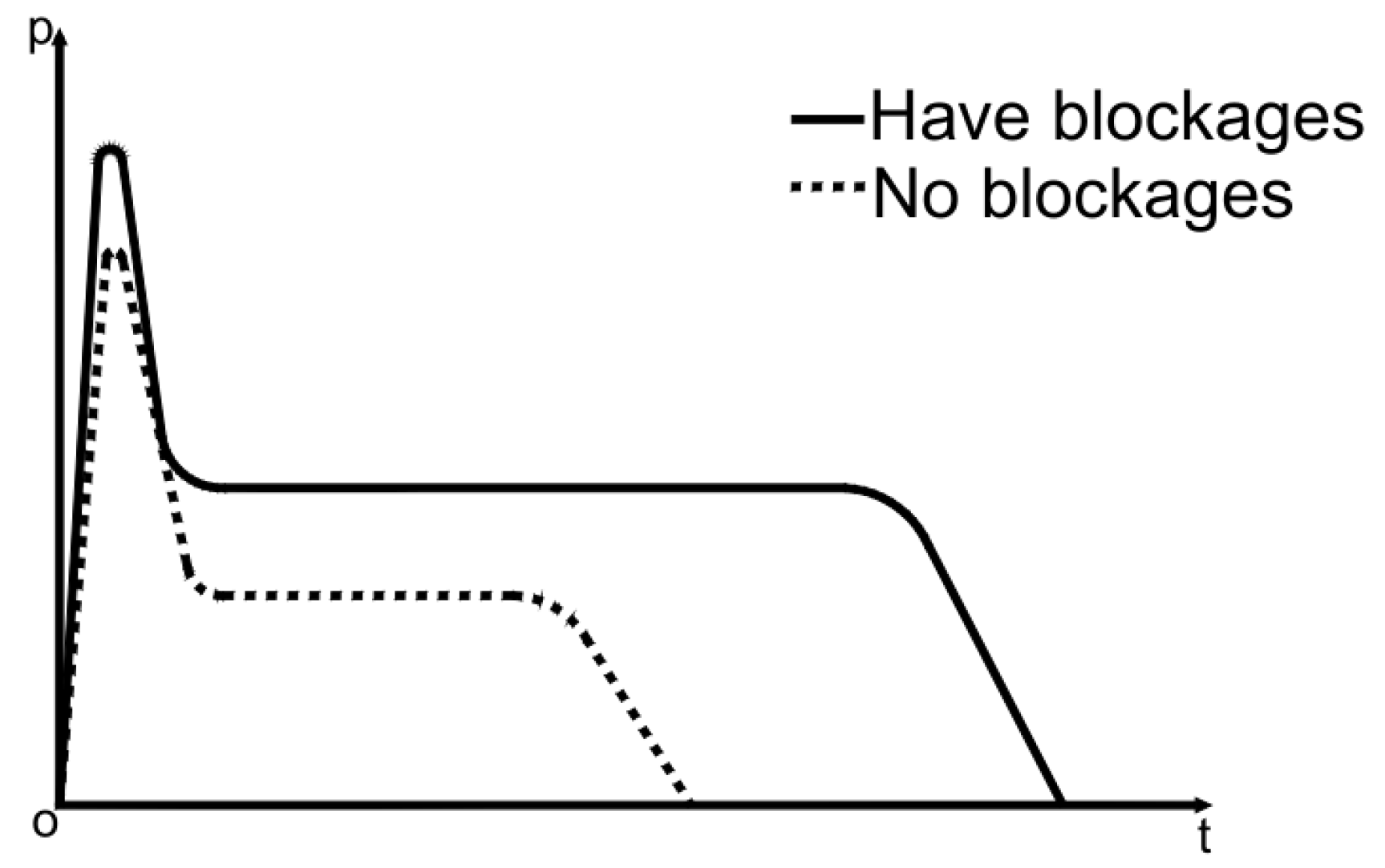
As shown in Figure 2, a gun hole in the case of no blockage, after the explosive explosion, the high temperature and high pressure gas generated will quickly rush out of the gun hole, so that the gas pressure quickly decays below the critical pressure. This process will also produce a lot of noise, and have a certain impact damage effect on the orifice. When the gun hole is blocked, the explosive gas will continue to act on the step rock mass due to the blocking effect of the blockage, and the rock mass can be fully broken to achieve a good blasting effect. When there is no tamponade or the quality of the tampon is not good, the action time of the explosive gas on the rock medium is very short, and there is not enough time for explosive gas breakage. It can be seen that the blockage can significantly increase the pressure of the blasted gas, delay the pressure decay time of the blasted gas, and promote the fracture propagation of the rock mass.

2.2. Analysis of Blockage Material Force and Damage Deformation

2.2.1. Plugging Material Force Analysis

The blockage body is in direct contact with the explosive in the gun hole, and the manifestation of the force mainly includes the destruction and pushing effect of the detonation wave; The destructive effect is the complete destruction of the bottom end of the blocked body by the detonation wave and the damage and damage of the internal structure; The pushing effect mainly includes the compression effect of the detonation wave on the blockage body and the movement of the tendency to punch.
1. The propagation law of the burst wave in the blockage material
(1)
Burst wave into the blockage material state
When the blast wave reaches the interface between the explosive and the bottom of the blockage material, transmission and reflection occur. When the wave impedance of the blockage is greater than that of the explosive, the shock wave is formed in the blockage and propagates upward, reflecting the shock wave to the lower charge. When the wave impedance of the plugging material is smaller than that of the explosive, the shock wave will be formed in the plugging material and the sparse wave will be reflected to the lower charge.
Set the initial parameters of the explosive ( P 1 ,   ρ 1 ,   u 1 = 0 ,   D 1 ), the initial parameters of the blast wave ( P H ,   ρ H ,   u H ), the initial parameters of the rock ( P m ,   ρ m ,   u m ), the parameters of the transmitted wave ( P 2 ,   ρ 2 ,   u 2 ), the parameters of the reflected wave ( P 2 ,   ρ 2 ,   u 2 ), and establish the continuity equation and the equation of motion for the incident, reflected and transmitted waves, and use the continuity condition of the transmitted wave at the interface ( P 2 = P 2 ,   u 2 = u 2 ) to obtain:
P 2 P 1 P H - P 1 = 1 + N 1 + N ρ 1 D 1 ρ m D 2
Among them,
N = ρ 1 D 1 ρ H ( D 2 + u H )
As the initial pressure of the explosive is much smaller than the pressure of the transmissive and blast waves, P 1 can be ignored, and the above formula can be reduced to:
P 2 = P H 1 + N 1 + N ρ 1 D 1 / ρ m D 2
Other parameters of the transmitted shock wave can be determined by the (Hugoniot) curve, as well as the principle of shock wave propagation. Through the above equations and principles, one can find the initial parameters of the shock wave of the blast wave into the blockage material.
(2)
The blast wave enters the blocking material propagation state
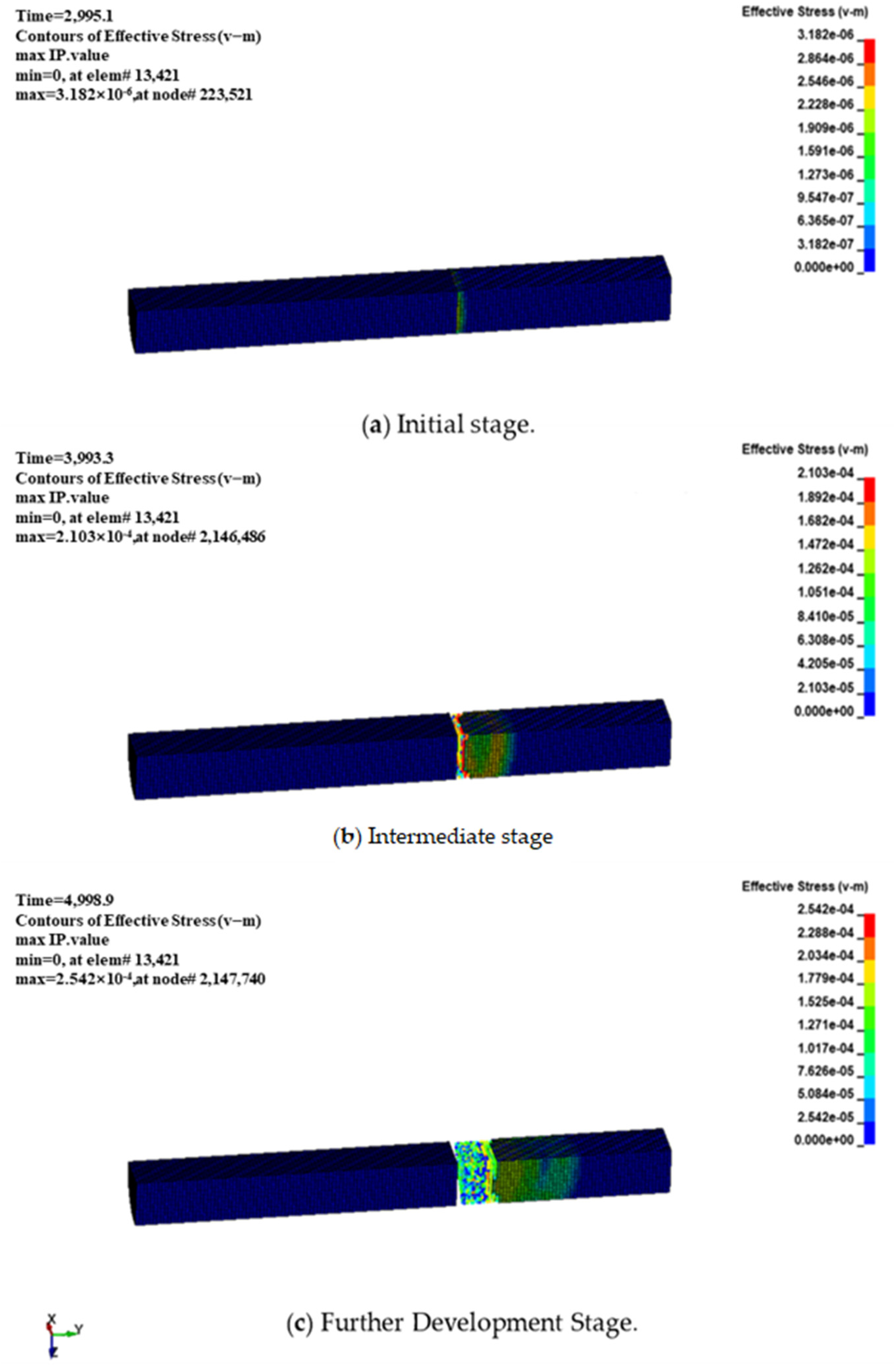
Select Hypermesh software to build the model, use LSDYNA software to calculate the model, and simulate the detonation wave into the blockage propagation state. As shown in Figure 3, place the explosive at the bottom of the blockage body to form a shock wave as far away from the center of the charge; the shock wave attenuates, the stress amplitude continues to decrease, and the wave velocity continues to decrease. In the near charge zone, the explosion load value is high, and the speed of the shock wave in the rock is supersonic, and the attenuation is the fastest; therefore, the state parameters of the rock passing through the wavefront are abrupt. During the detonation wave propagation process, the expansion of the shock wave front leads to a decrease in the energy density of the wave front per unit area, and correspondingly, the peak of the stress wave at the top of the plugged body is significantly smaller than the bottom end of the plugged body.
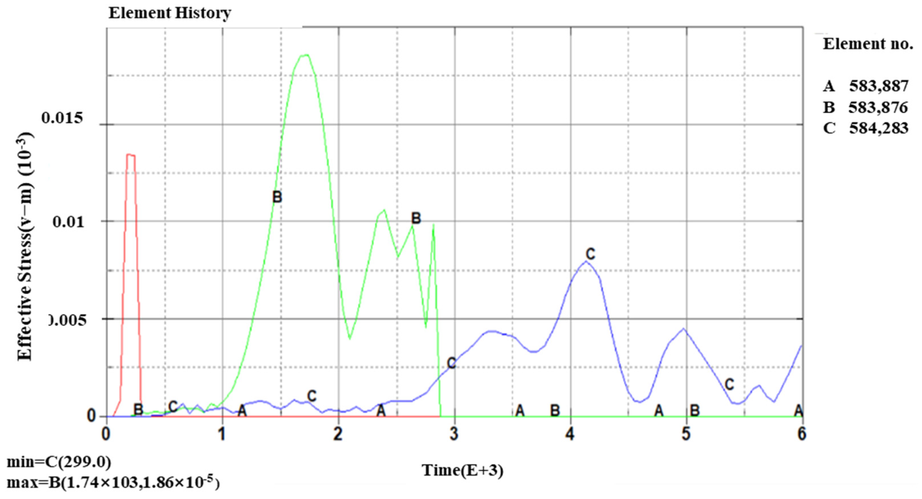
The effective stress of different sections of the plugging is statistically shown in Figure 4. The explosion generated by the blast wave from the bottom of the blockage material to the top of the transfer process, the bottom of the first impact of the blast wave, the bottom of the stress (A point) in the moment of detonation that reached a peak, based on the role of explosives in the rock “three circles” range theory, the bottom of the crush zone, where the blockage will not be able to withstand the high pressure, is completely crushed. The middle of the blockage material (point B) is subject to greater stress, and the stress fluctuations show a certain periodicity, and the top of the blockage material (point C) is subject to the longest duration of stress.

2.2.2. Analysis of the Damage Process of Blockage Material by Dynamic Load Impact

In this paper, the dynamic mechanical properties and dynamic load damage process of blockage materials are analyzed by the joint TrueGrid+LS-DYNA modeling simulation method. The geometric model is divided into bullet, incident rod, test piece, and transmission rod, where all the rods are of the same material to ensure consistent wave impedance. The HJC material model is selected for the specimen material, which has similar mechanical properties to the blockage material (geopolymer); the properties are shown in Table 1.
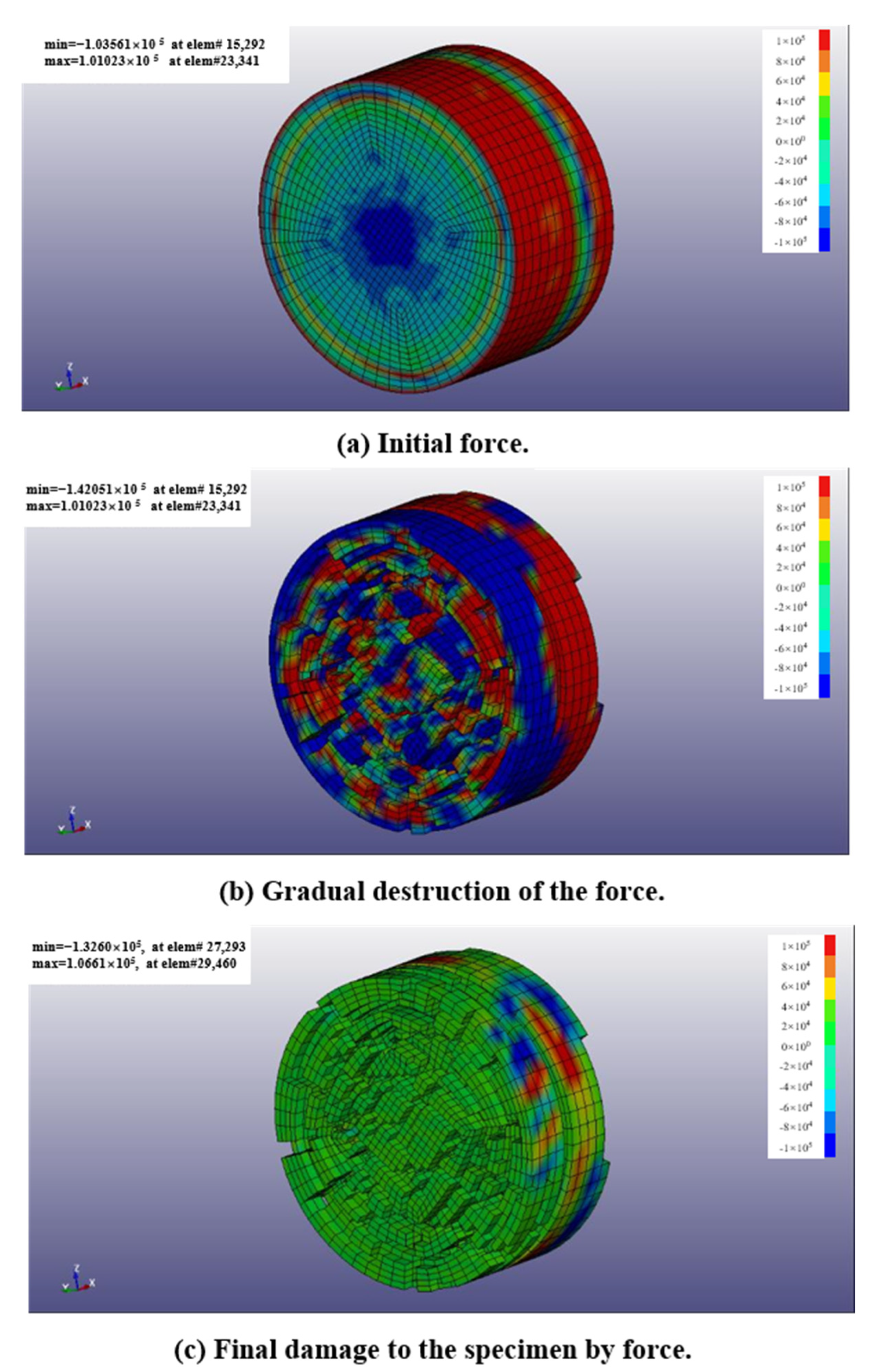
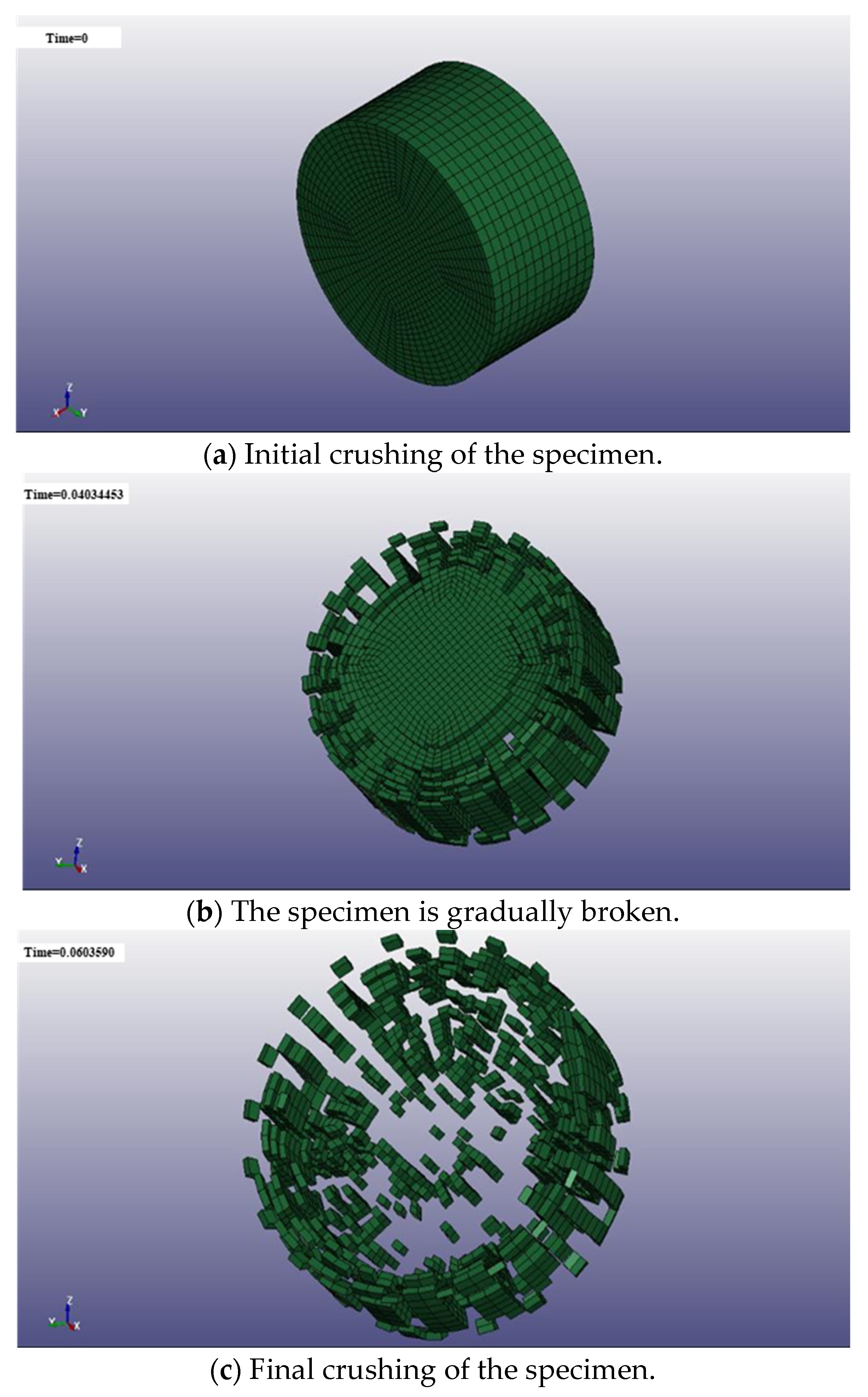
Under the dynamic load impact of the geopolymer-modified plugging material, the force performance is shown in Figure 5, the force on the edge of the hole in the initial stage is greater than the center position of the hole, and the stress is gradually transferred to the center position of the hole in the process of gradual failure, and the stress area of the sample is uniform when the final failure of the specimen is reached.
The failure process of the specimen shows the failure of the piece, and the crushing degree reaches the crushed stone gradation, which can better realize the crushed stone loading operation (Figure 6).

2.3. Analysis of Gun Hole Blockage Movement Law

2.3.1. Numerical Simulation Study of Blockage Material Motion

Hypermesh software was selected to construct the model, and LSDYNA software was used to calculate the model. The high energy explosive model MAT_HIGH_EXPLOSIVE_BURN is used in this calculation, where BETA has three types and takes the value of 0.0 in this paper modeling. The air material used is the *MAT NULL material model, and linear polynomial EOS LINEAR POLYNOMIAL is used to represent the ideal gas. *MAT_PLASTIC_KINEMATIC is the plug material model, and the algorithm uses the SPH algorithm. In this paper, the plugged body is studied by numerical simulation.
(1)
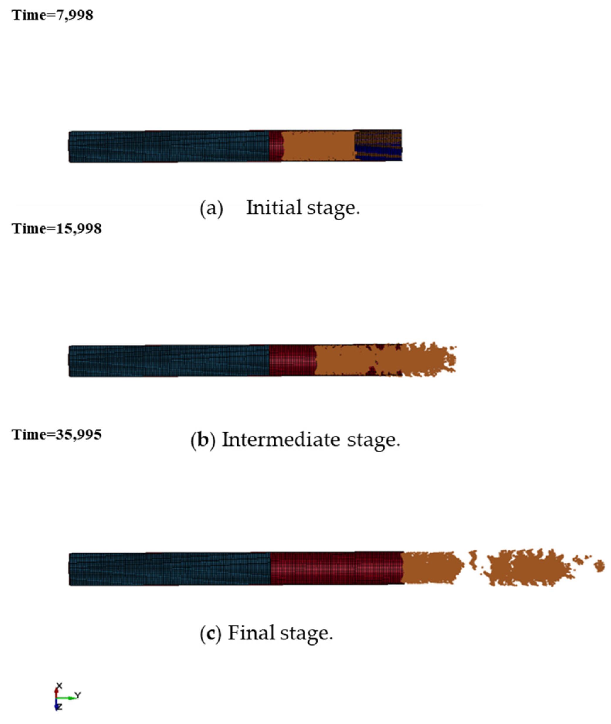
Analysis of the dispersion process of the blockage
The gun hole and plugging parameters were determined according to the blasting of the deep hole step of the open-pit mine, and the length of the gun hole was 9 m and the plugging length was 7 m. The damage of the detonation wave to the plugged body will affect the movement process of the plugged body as shown in Figure 7, in the figure, blue is the rock foundation, yellow is explosives, red is the ground polymer blocking material, and the range of action of the detonation wave in the rock is manifested as crushing zone, fracturing zone and vibration zone.
(2)
Analysis of motion parameters of the blockage body
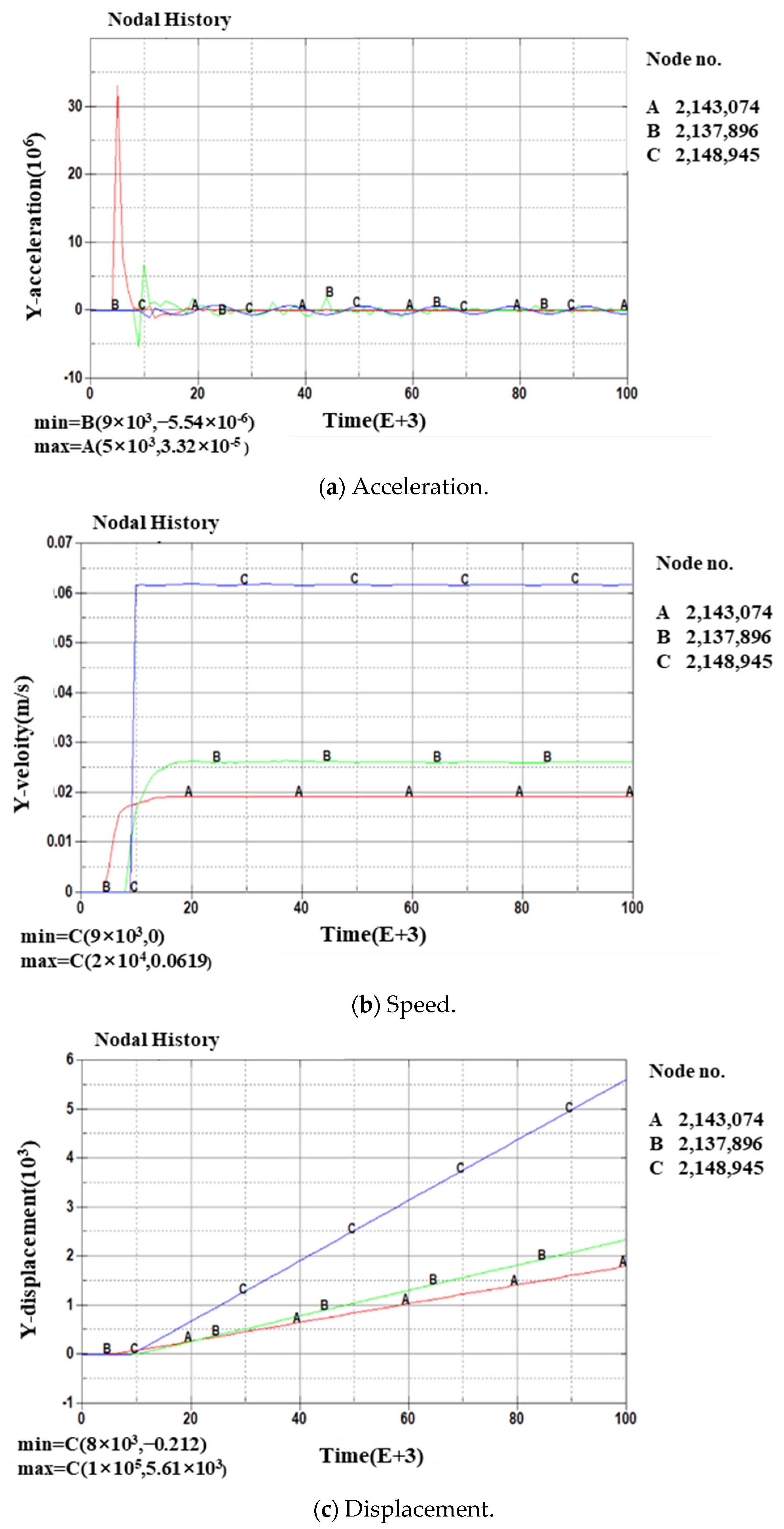
As shown in Figure 8, the acceleration of the blockage from the bottom to the top gradually decreases, and the acceleration of the bottom, middle, and top blockage has a negative value. On the one hand, when the stress wave propagates to the free surface, it will form a reflective stretch wave at the orifice, and has a certain tensile effect on the filler to cause a variable acceleration movement with reduced acceleration. On the other hand, it is because the upper blockage body physically limits its movement, creating resistance. The motion manifestations (velocity, displacement) of the blockage gradually increase from bottom to top. The top blockage can obtain greater speed and larger displacement, while the bottom blockage only forms a large acceleration, but obtains less speed and less displacement.
The bottom plugging material (point A) in the direct action of the burst wave, the instantaneous access to great acceleration, while the material is completely broken by the high pressure, the plugging material in the middle of the plugging effect, only to obtain a certain speed and partial displacement, thus occurring in the plugging material compression. Therefore, the bottom plugging material in the burst of gas action at the beginning, mainly to complete destruction and large compression deformation.
The middle blockage material (point B) is subject to both the burst wave and the bottom blockage material to promote the action, but also by the top blockage material of the clamping force. Its acceleration of motion compared to the bottom blockage material is much smaller, mainly located in the rock explosive “fissure area”, and the energy of the blast wave is significantly reduced. The middle blockage material speed and displacement lags behind the bottom blockage material, indicating that further compression of the blockage material occurs.
Top plugging material (C point) of the movement of the main burst of gas and the lower plugging material promote the two components. In the plugging performance of the poor plugging material, such as the simulation for the bulk plugging material (rock powder), the burst of gas through the plugging material itself fissures can directly push the top plugging material. The top plugging material does not exist in the direction of motion constraints, so its speed can reach the maximum; once the speed is reached, immediately produce displacement, and punch out of the hole.

2.3.2. High-Speed Photography to Monitor Clogging Punch Movement

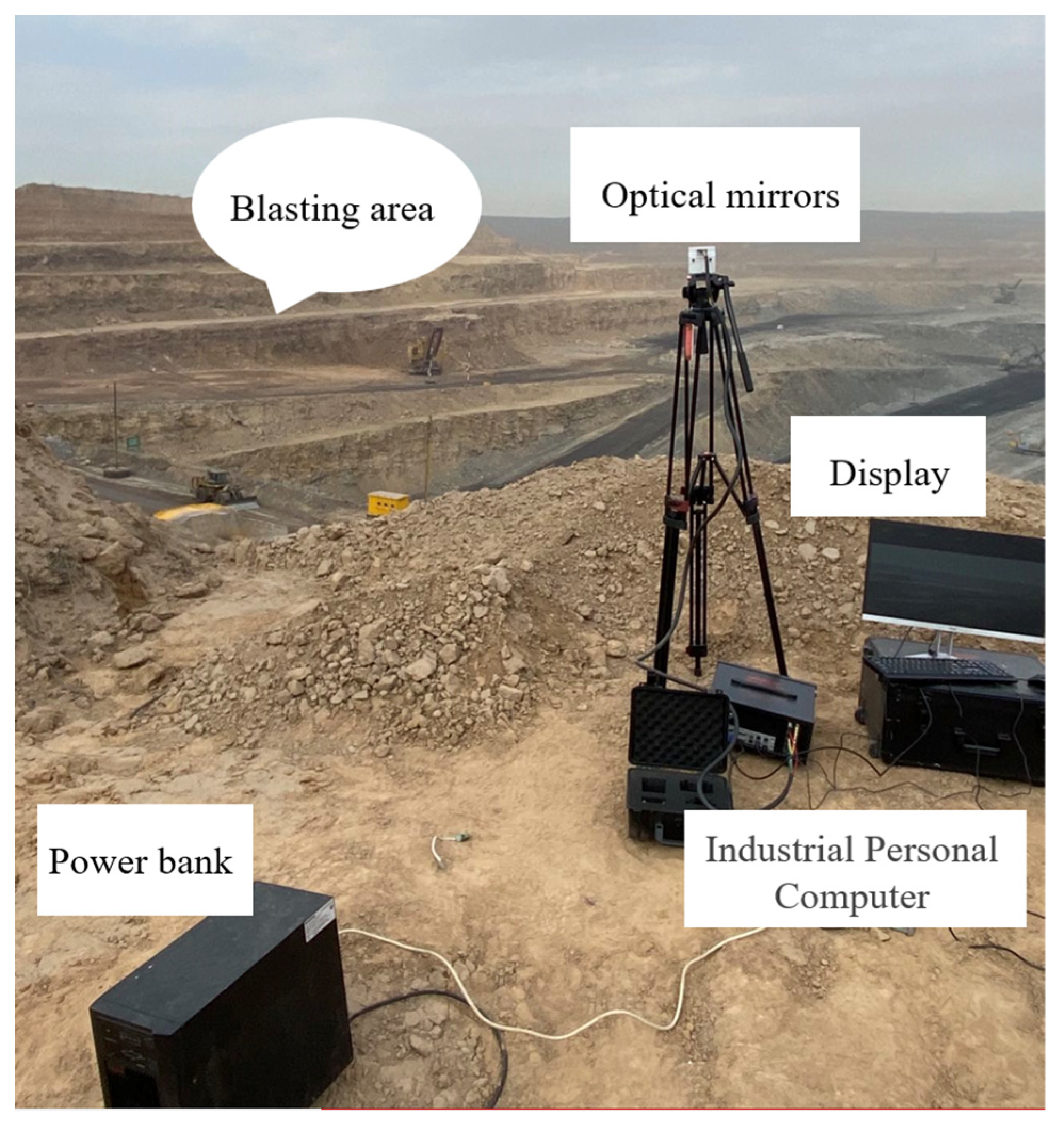
Open-pit step blasting is an activity in which rock damage occurs within a very short period of time, and it is appropriate to use high-speed photography to observe the dynamic parameters of the blasting process. Figure 9 uses high-speed photography in open-air step blasting for both macroscopic analysis of the blasting dynamic process in the blast area in space and time, obtaining high-speed video images of open-pit blasting, and quantitative analysis of the temporal and spatial displacement changes of the rock mass, enabling observation of blockage punching or not, calculation of blockage punching motion parameters, and analysis of flying rock motion distance. In this paper, an experiment based on high-speed camera monitoring of the plugging motion of the gun hole was carried out at the Pinshuo East Open Pit Mine.
1. Shooting equipment and parameters
The Acuteye high-speed image system was used to build a high-speed photography system for open pit mines. The system consisted of a high-speed camera, an industrial control computer, an optical lens, a mobile power supply, a display screen, and a keyboard and a mouse. The shooting frequency of the high-speed camera was adjusted between 1000~5000, which could clearly record the dynamic process of step blasting, and the exposure time and exposure were set according to the system reference value, as shown in Table 2.
2. Qualitative analysis of the process of punching motion of the hole blockage
(1) Trajectory analysis
After the plugging material rushed out of the hole, it almost moved upward along the axial direction of the hole, and the overall trajectory was approximately a vertical straight line. The trajectory of the plugging material illustrated that when the plugging material reached the hole surface, the rock near the upper wall of the hole and the hole surface position could relatively keep the structure intact, and the movement of the plugging material in the hole was approximately a one-dimensional movement.
(2) Integrity analysis
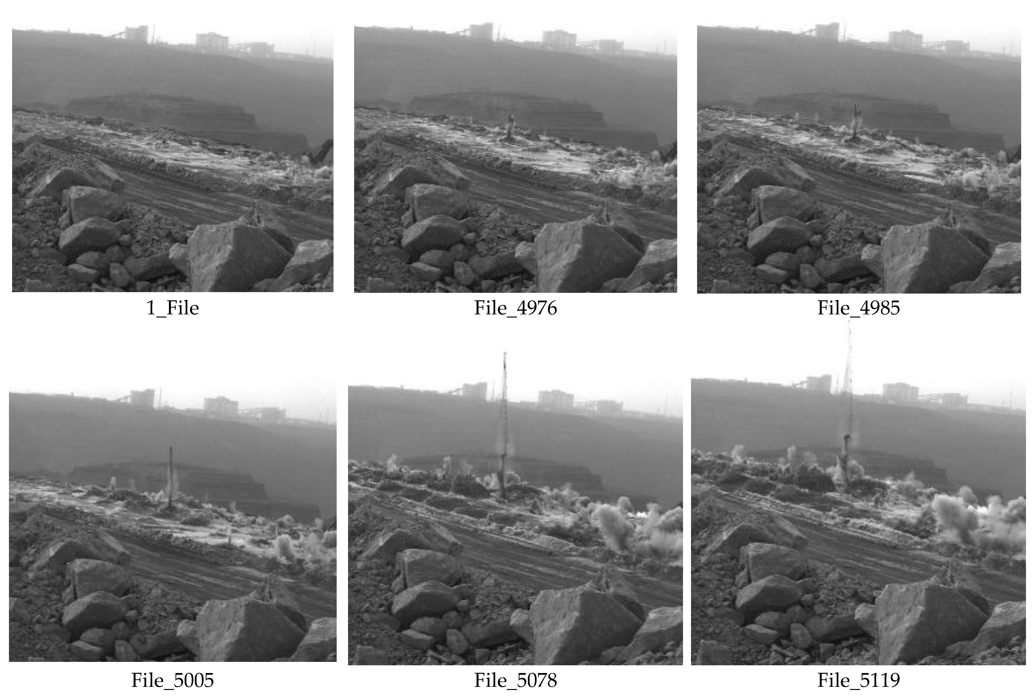
When the plugged body makes an upward movement in the air, it separates segment by segment. This shows that the assumption that the blockage body completes compression at the moment of detonation should be constrained in the stage where the plugged body has not yet punched out of the gun hole, in the same way, the mechanism analysis of the movement law of the blocked body shows that the assumption that the plugged body is approximately a rigid whole is not applicable to the movement of the plugged body after breaking out of the hole. The hole blocking punching process is shown in Figure 10, the number in the figure is the number of photos taken by the camera over time, 1_File represents the beginning of the movement of the plugged body, and File_5119 represents the movement of the plugged body to the highest point. Other numbers represent intermediate processes in the punching motion.
3. Quantitative analysis of the process of punching motion of the hole blockage
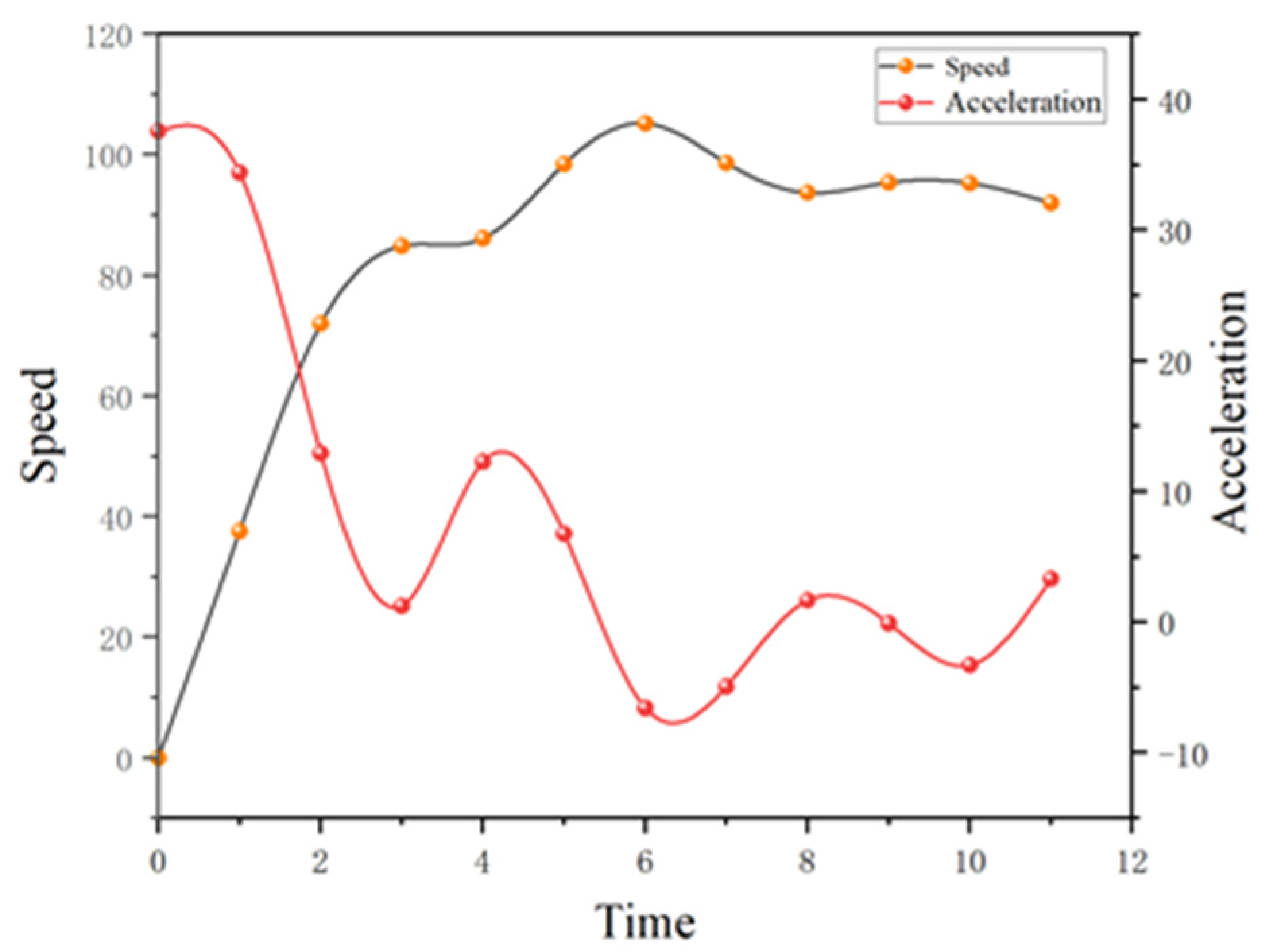
This paper uses Digimize software to capture and measure the motion height of the blockage, and Digimizer can automatically identify the image content, such as in Table 3, to accurately measure the picture and calibrate the displacement during the movement of the blockage. The capture frame rate for this shot was 1000 and the interval time of the picture frames was 1 ms. In calculating the motion parameters of the blockage after punching the mouth, the change in the magnitude of the motion parameters (displacement, movement) per unit time was studied.
After the plug material was flushed out of the hole, the acceleration decreased as a whole, from accelerated deceleration to deceleration. The plugging material obtained the maximum acceleration when punching out the hole, and then the acceleration rapidly decayed and maintained positive acceleration for a period of time, which indicated that the plugging material still obtained the upward thrust after punching out the hole, and the analysis was that the shelling gas was ejected from the hole, which played a pushing role for the plugging material still in the hole. Subsequently, the acceleration of the plugging material showed some fluctuations, and the overall acceleration was close to the acceleration of gravity, which was similar to the free fall motion of the object in the air. On the one hand, the smaller blocking masses with better performance got rid of the constraints of the larger blocking masses; on the other hand, the lower blocking masses with better performance crossed the upper blocking masses, and since the displacement was calibrated to the top of the whole blocking masses, the recorded acceleration showed a certain increase.
As shown in Figure 11, after the blockage body rushes out of the gun hole, it begins to accelerate the movement, and reaches maximum speed after accelerating for a certain time; at this time, the speed of the blockage body fluctuates in a certain amplitude, and the reason for the analysis is the same as the acceleration fluctuation, which is that the bulk of the blockage body and the different internal blockage groups have different motion performances. Subsequently, the velocity of the blockage decreases, similar to the free fall motion of the object in the air.
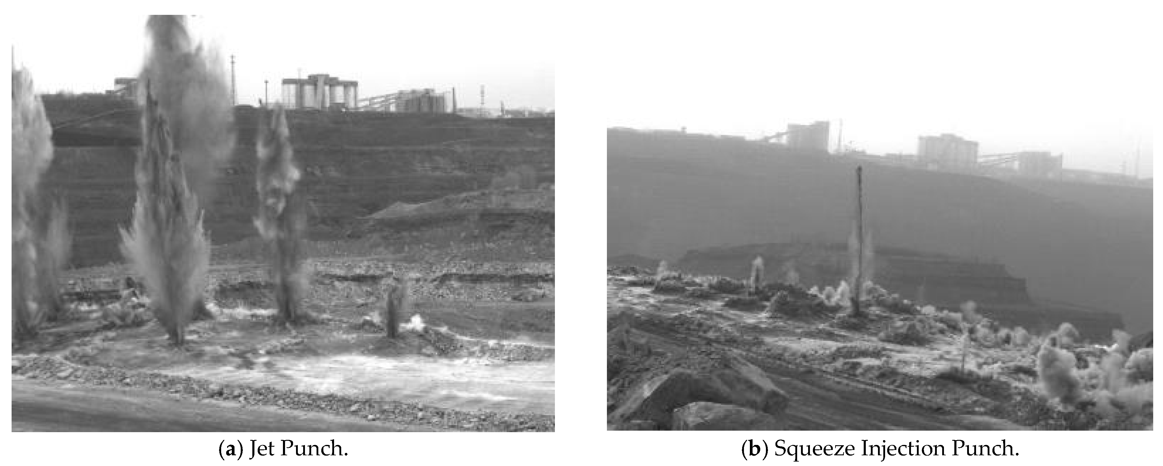
After several high-speed photographic observations of the open-pit mine blockage, as shown in Figure 12, it was found that the motion performance of the plugged body after punching was very different, and the thrust-out speed of the stuffed material was 40–80 m/s. From the shape of the plugged material after punching, it can be divided into jet punching and squeeze injection punching. In jet punching, the plugging material will expand in radial and axial directions with a large area after punching out the hole, where a large amount of plugging material is flushed out of the hole. In squeeze injection punching, the plugging material mainly moves upward in the axis of the hole and expands in a smaller area in the radial direction, at which time only a small amount of plugging material is flushed out of the hole. The different forms of punching are mainly caused by the different degrees between the amount of charge and the plugging performance. When the amount of charge is obviously larger than the plugging capacity, jet punching is likely to occur, and when the amount of charge is only slightly larger than the plugging performance, squeeze injection punching is likely to occur. Compared to the problem of a large number of explosive gas leaks from jet punching, squeeze injection punching can better delay explosive gas.

3. Results and Discussion

3.1. Indoor Test Results

Geological polymer is selected as the modified material for blockage, which is a substance containing aluminosilicate under the action of alkali excitation, polycondensation reaction occurs, forming a product with the same properties as natural rock. Geological polymer has the characteristics of high strength in the early stage, and its strength after 24 h can reach 20~30 MPa. The reaction of geopolymers is divided into three steps, starting with the hydrolysis of aluminates in an alkaline environment, followed by the condensation reaction of silica-alumina salts, and finally, the reorganization of the condensation products to form a complete network architecture.

3.1.1. Experimental Design for Geopolymers

The geopolymer proportioning design needs to consider the maintenance conditions, alkali exciter ratio, water-cement ratio, and cement-sand ratio. Among them, the maintenance condition is chosen from the perspective of a field test application, the normal temperature, and short maintenance time (2 h~12 h). The ratio of composite alkaline exciter of water glass and sodium hydroxide is 1.2–2. The water-cement ratio refers to the ratio of water (including alkali solution) to cementing material in geopolymerization, and the water-cement ratio selected in this test is between 0.25 and 0.5. The cement-sand ratio refers to the mass ratio of cementing material to the blended aggregate (rock powder), and, in this experiment, the cement-sand ratio is 1:3. In the initial stage of the test, a total of six groups of different material ratios were designed for the test, as shown in Table 4.
1. Test material preparation and specimen preparation
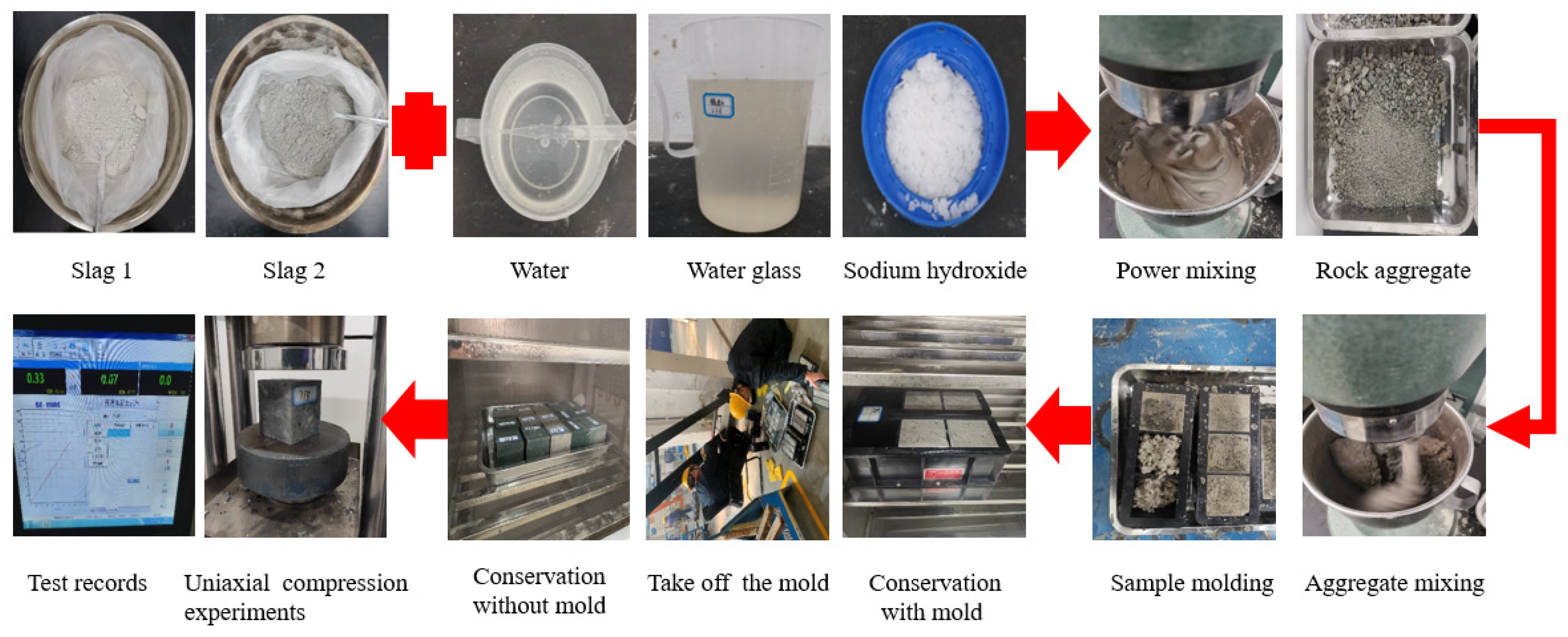
As shown in Figure 13, the rock powder is first screened to screen out the rock slag blocks that are too large in size. The slag and rock powder raw materials are evenly spread in the tray and weighed on the electronic balance according to the designed ratio, then the slag powder and rock powder solid materials are mixed and poured into the mixer, and stirred until uniformly mixed. Then, water, sodium hydroxide solution, and water glass are mixed and poured into the mixer and stirred until uniform. The prepared geopolymer material is loaded into the mold and vibrated on the shaking table. The prepared specimens are numbered and maintained indoors, and the maintenance is completed for mechanical experiments.

3.1.2. Mechanical Properties of Geopolymer-Modified Rock Powder Plugging Materials

China University of Mining and Technology apparatus WDW-300 electronic universal testing machine was used. As shown in Table 5, the uniaxial compressive test of each ratio is performed five times, and the average result of compressive strength is taken as the maximum stress value. The test results were calculated as the compressive strength according to the following formula.
Rc = P/A
In the above equation, Rc—uniaxial compressive strength of the specimen, MPa.
P—specimen load at damage, kN.
A—specimen cross-sectional area, m2.
Uniaxial compressive specimen size are 70 mm × 70 mm.
This paper focuses on providing a theoretical analysis, experimental proportioning, safety assurance, and field application of geopolymer material modified rock powder. A4–A7 improves the admixture of rock powder, among which the strength of A5 and A6 is more ideal. Considering the economical factors in field application, this thesis selects A3, A5, and A6 ratios for the field test reference group. Combined with the compressive strength, it was finally determined that the geopolymer plugging material modification choice was A6: 700 g of rock powder, blended with 200 slag, with 40 g of NaOH solution (30%), 140 g of water glass with modulus 3.2 and 80 g of water.

3.2. Field Test Results

Plugging Material Modification Field Test Engineering Applications

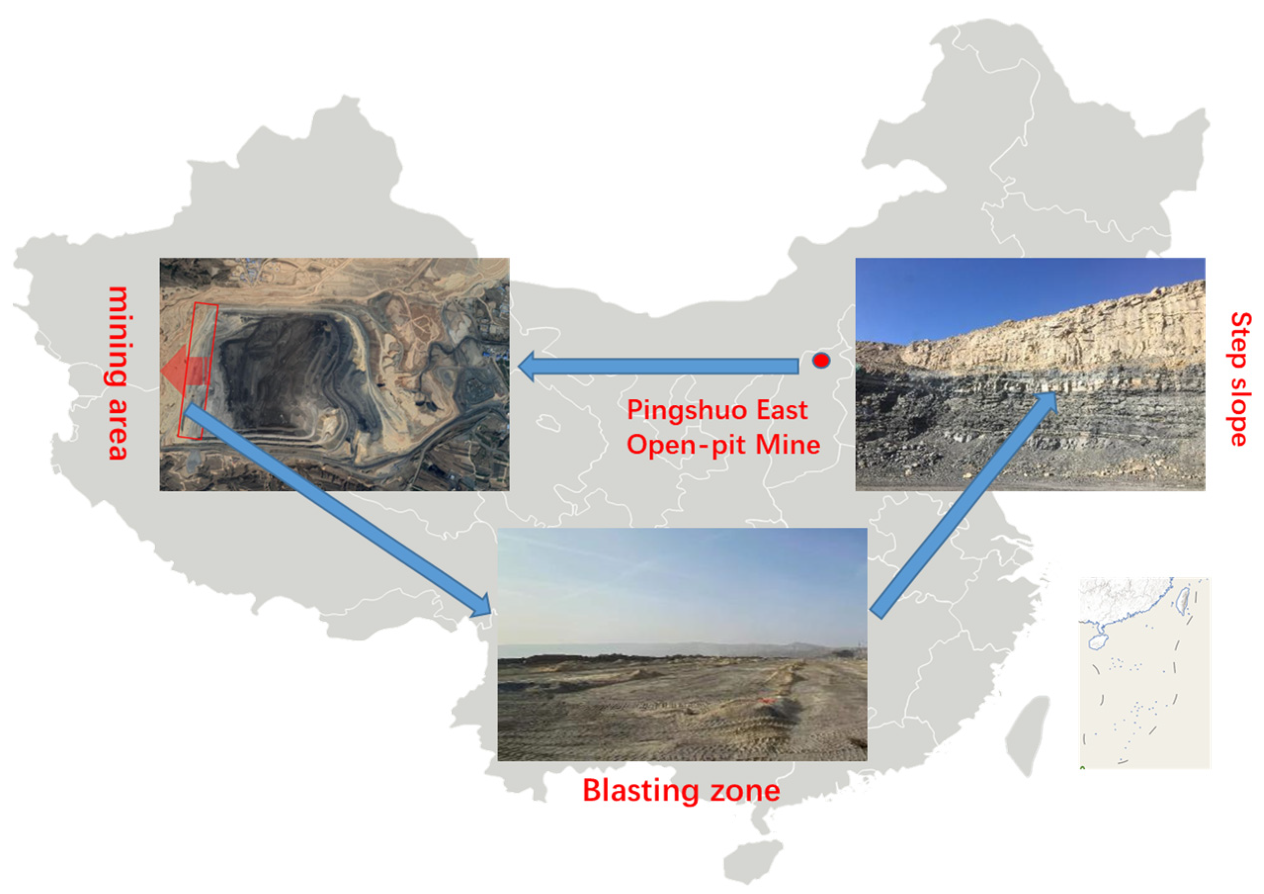
The field experiment base was selected as the Pingshuo East Open-pit Mine, as shown in Figure 14, the total mine is 4.42~5.47 km long from east to west, 6.53~10.3 km wide from north to south, and the total exploration area is 48.73 km2. The East Open-pit Mine is located in the northeast of Pingshuo Mining Area, about 10 km northeast of Pinglu District, and 28 km away from Shuozhou City at 359°. Its geographical coordinates are: 112°23′58″~112°27′52″ E, 39°29′58″~39°35′33″ N. The stripping steps of the mine area are nearly horizontal multi-layer sedimentary rock structures, including mudstone, coarse sandstone, sandy rock, fine sandstone, medium sandstone, and siltstone. From the perspective of horizontal extension distribution, on the whole, the production status of each rock layer is relatively stable, the lithology has a certain continuity, and the boundary of the rock layer is clear.
The drilling form is vertical drilling, for the convenience of construction, q rectangular method is adopted, the parameters are shown in Table 6. Explosives using porous granular ammonium oil fry, a detonation system using conventional non-electric detonators, a Cordtex™ detonating cord and a Pentex™ detonation device, spacers using air spacers, were used. The detonation sequence is diagonal with a 42 ms delay between the first row of holes, 60 ms delay between the second row, and 600 ms delay between the detonators in the holes.
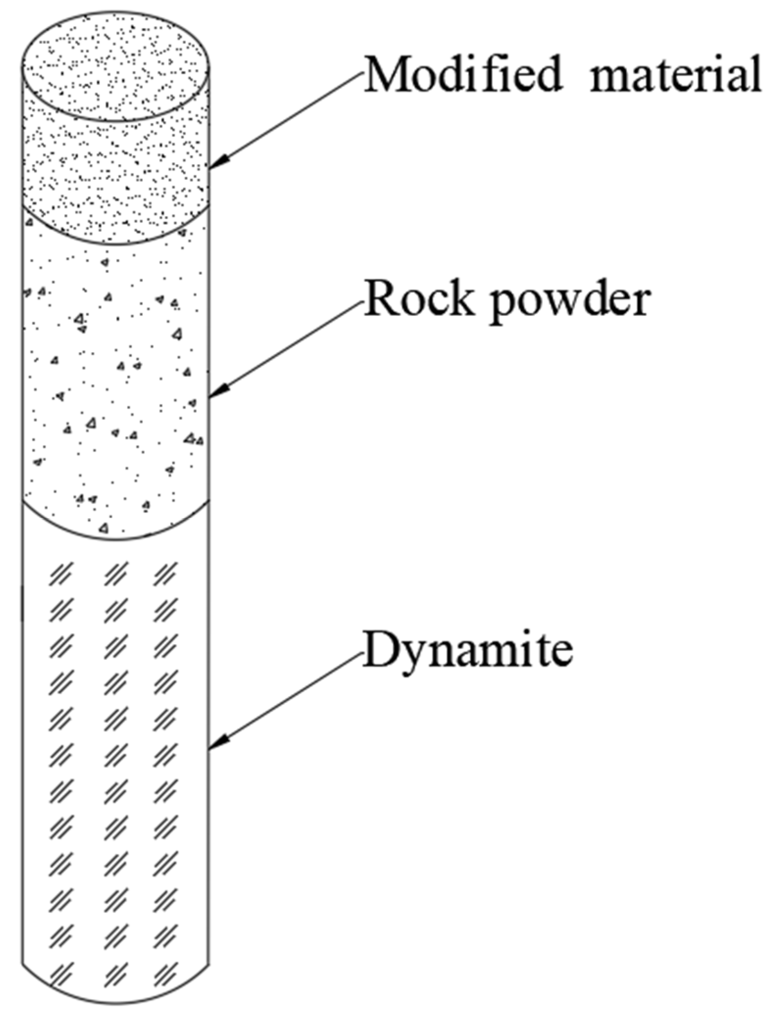
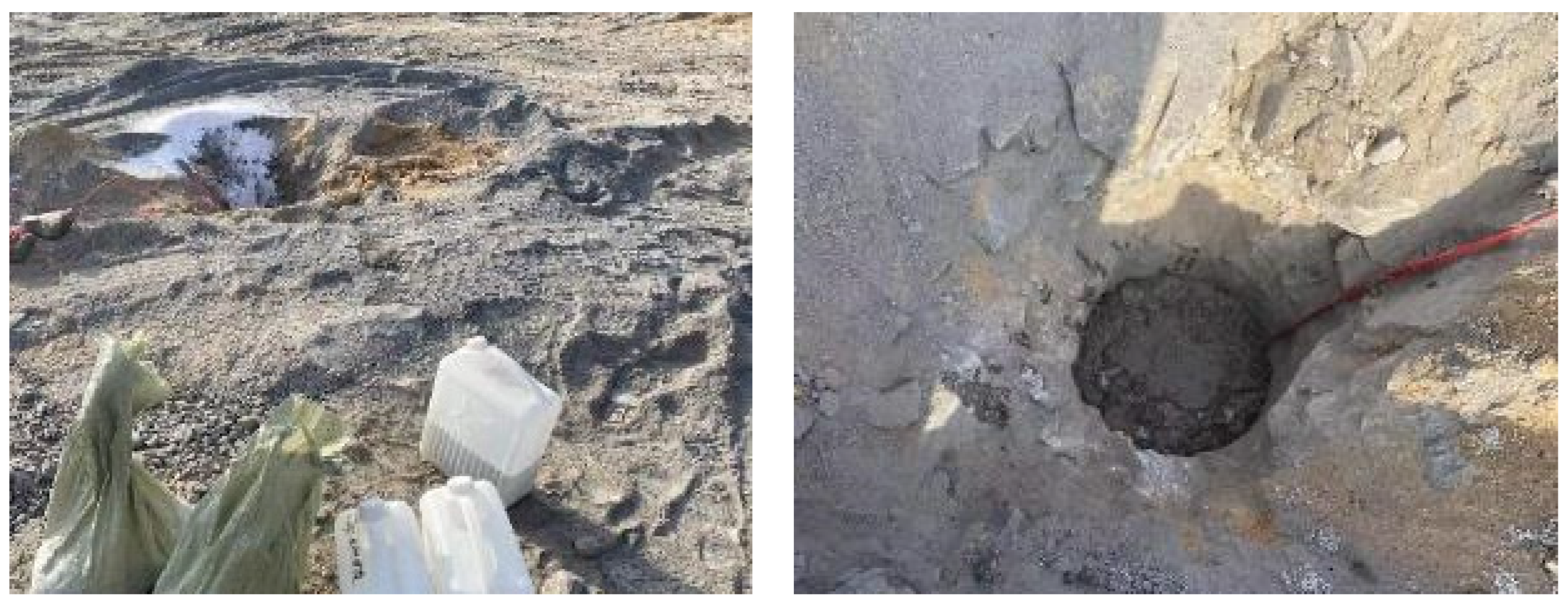
Using Table 7 modified material laboratory ratio scheme, as shown in Figure 15, rock powder, slag, NaOH solution, water glass, water are proportionally configured, and the construction is carried out by artificial mixing in accordance with Figure 16 on site, first the slag and rock powder are mixed evenly, and NaOH solution, water glass, and water are poured into the amount of NaOH solution, water glass, and water, and the shovel is constantly stirred until the mixed material is in the shape of a flowing slurry, and finally filled in the gun hole (the length of the modified material is 2 m).
In the production test blasting area with a segmental structure, the original rock powder blockage was adjusted to a compound structure of geopolymer-modified blocking material and rock powder blockage, with the upper part being geopolymer-modified blocking material and the lower part being rock powder. The geopolymer modified material was applied to optimize the blasting effect under the premise of ensuring blasting quality. In a deep hole open-pit mine, the use of sectional structure loading can increase the charge center, increase the explosive charge in the middle and upper part of the step, increase the energy applied to this part of the rock, and thus reduce the bulk rate in the upper part of the step.
As shown in Figure 17, in the same production explosion area, the use of zoning loading different plugging materials, while, after detonation, the use of a high-speed camera capture to monitor the movement of different plugging materials, fill plugging materials as follows, the red part of the use of segmental charging into the geopolymer modified plugging material plus the original rock powder, the yellow part of the entire loading into the original rock powder, as shown in the figure below.

3.3. Blasting Test Engineering Effect Analysis Study

3.3.1. Blocking Effect of Sectional Charging

Figure 18 shows a high-speed photographic recording, the blockage modified material test area is obviously contrasted with the original rock powder blockage area, in which the overall blockage of modified material test area is better, only a smaller punching occurs in one hole at the southwest corner, and the punching height is not more than 10 m, while a larger scale punching occurs twice in the middle of the original rock powder blockage contrast area, and the blockage punching volume and a large amount of rock around the hole are flushed out, and the punching height reaches 30 m, and a smaller-scale punching occurs at the northern boundary, with a punching height of about 10 m. It can be seen that the geopolymer-modified plugging material has better plugging performance than the original rock powder plugging.

3.3.2. Blasting Block Size Distribution and Large Block Rate

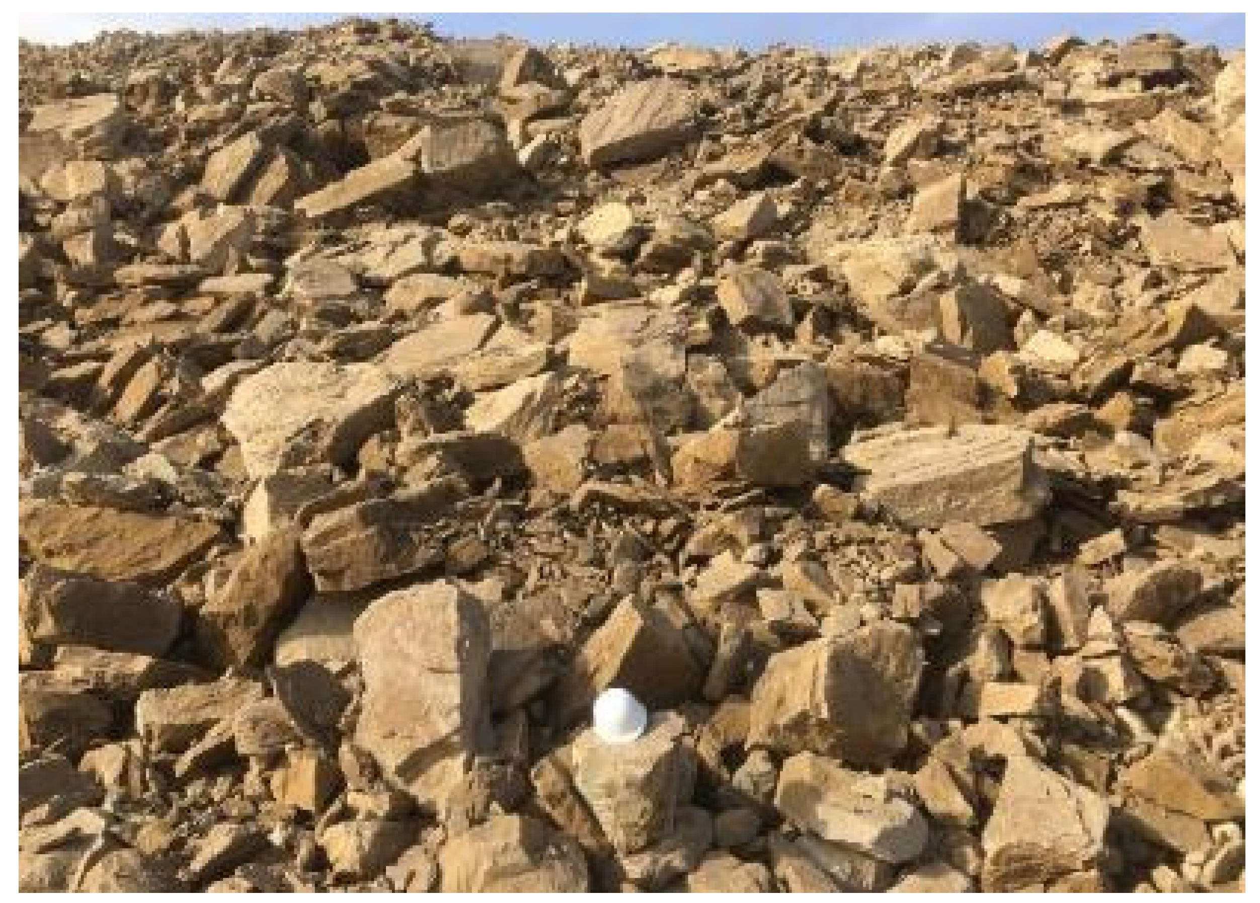
Rock crushing chunks are expressed in terms of maximum linear diameter, equivalent ball diameter, and triaxial diameter. The criterion for chunking depends on the size of the operating equipment and, in general, chunks should not exceed the minimum linear size of the electric shovel. The East Open-Pit Mine is operated by an electric shovel from the 1320 level to the 1350 level with a minimum bucket capacity of 35 cubic meters and a minimum linear size of about 3 m. Based on this data, the maximum linear size of block allowed is calculated to be 2.6 m.
The special software process based on Split-Desktop open-pit blasting block analysis is shown in Figure 19, Figure 20 and Figure 21, and the bulk analysis of the blast heap is performed as follows.
(1) Photo import. On the surface of the blast pile, put a reference, take pictures of the blast pile, reference as far as possible in the blast pile below and above the blast pile placed one each, to be used to reduce the distance between the near and far small—size effect.
(2) Reference and accuracy settings. Set the image recognition parameters, mainly: the reference size, fine particle factor, boundary recognition accuracy, etc.
(3) Calibration of reference size, automatic calibration of rock block boundary, recognition of rock block contour.
(4) For the rock block boundary delineation results to view, you can modify the adjustment results.
(5) The output results, including the blast stack block degree distribution graph and grade.
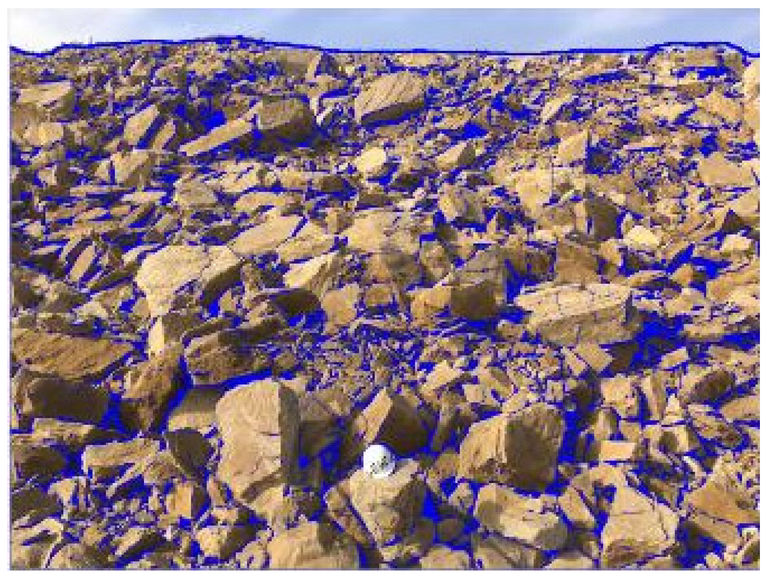
The image recognition results are shown in Figure 22. The maximum block size of the test area is 127 cm, of which nearly 90% of the rock block size is below 57.11 cm. Combined with the needs of the front loader, electric shovel, crushing plant feeding, and on-site construction, the critical size of the large block is positioned at 1.2 m, and the proportion of the large block in this area is almost 0%; that is, from the block size characteristics of the surface reaction of the blast pile, the blasting effect is very good, and there is almost no large block. The maximum block size in the contrast zone is 150 cm, of which nearly 90% of the rock block size is below 65.36 cm.
In the actual production area, the comparison area and the test area were divided in half from north to south, and the plugging structure of “geopolymer-modified plugging material + rock powder” was adopted in the test area, and the test results showed that the geopolymer-modified plugging material had superior plugging performance and could reduce the block rate in the upper part of the step.
The solution fully considers the potential improvement of the blocking performance of the geopolymer-modified blocking material on the blasting economy, not only applying the improvement of the blocking performance to the improvement of the blocking effect of a single hole, but also extending the improvement of the blocking performance to the impact of the adjustment of the blasting process parameters on the blasting economy, by reducing the density coefficient of the blast hole, reducing the number of holes, and reducing the scale of the drilling of the holes, which can reduce the penetration blast workload and reduce operating costs.

4. Conclusions

In this paper, the mechanism of blasting plugging action and modified plugging materials in an open-pit mine are studied by using mechanism analysis, indoor experiments, and field tests. The study focuses on the force deformation of the blasting plug in the blast hole and the movement characteristics in the blast hole. In this paper, geopolymers are introduced into the field of blast hole plugging materials, and material proportioning experiments are carried out to propose a better solution for geopolymer-modified rock powder plugging. Finally, this paper applies the aforementioned theoretical and indoor research results to open-pit blasting and demonstrates the superior plugging performance of geopolymer-modified rock powder plugging. The main conclusions are as follows.
1. The motion performance (velocity and displacement) of the plugging materials all gradually increase with the bottom to the top. Among them, the top of the plugging material can obtain greater velocity and displacement, while the bottom of the plugging material does not have outstanding motion performance (velocity and displacement) after flying out of the hole.
2. The geopolymer-modified plugging material has a superior plugging property, reliable safety, and can be applied to the plugging of shell holes. Its better solution is: 700 g of rock powder, mixed with 200 slag, with 40 g of NaOH solution (30%), 140 g of water glass with modulus 3.2, and 80 g of water as the base ratio.
3. In the sectional loading structure, the plugging structure of “geopolymer-modified plugging material + rock powder” can ensure better plugging of the shell hole, while reducing punching and flying stones, and effectively reduce the rate of large blocks in the upper part of the step.

Author Contributions

Conceptualization, X.D. and Z.A.; methodology, Z.A., X.L., S.X. and B.X.; validation, X.D., M.W., R.G. and D.Z.; formal analysis, Z.A.; investigation, X.D.; resources, X.L.; data curation, X.L.; writing—original draft preparation, X.D., Z.A. and M.W.; writing—review and editing, B.X. and R.G.; visualization, Z.A. and D.Z. All authors have read and agreed to the published version of the manuscript.

Funding

This paper was supported by the National Natural Science Foundation of China (52174131; 52004202).

Institutional Review Board Statement

Not applicable.

Informed Consent Statement

Informed consent was obtained from all subjects involved in the study.

Data Availability Statement

Not applicable.

Acknowledgments

The author would like to thank Pingshuo East Open-pit Coal Mine for providing an important test base for this paper.

Conflicts of Interest

The authors declare no conflict of interest.

References

  1. Koteleva, N.; Frenkel, I. Digital Processing of Seismic Data from Open-Pit Mining Blasts. Appl. Sci. 2021, 11, 383. [Google Scholar] [CrossRef]
  2. Wang, Z.X.; Jia, G. Existence and multiplicity of nontrivial solutions to the modified Kirchhoff equation without the growth and Ambrosetti-Rabinowitz conditions. Electron. J. Qual. Theory Differ. Equ. 2021, 1–18. [Google Scholar] [CrossRef]
  3. Wang, Z.M.; Zhou, W.; Jiskani, I.M.; Ding, X.H.; Luo, H.T. Dust pollution in cold region Surface Mines and its prevention and control*. Environ. Pollut. 2022, 292, 118293. [Google Scholar] [CrossRef]
  4. Wang, Z.M.; Zhou, W.; Jiskani, I.M.; Luo, H.T.; Ao, Z.C.; Mvula, E.M. Annual dust pollution characteristics and its prevention and control for environmental protection in surface mines. Sci. Total Environ. 2022, 825, 153949. [Google Scholar] [CrossRef]
  5. Luo, H.T.; Zhou, W.; Jiskani, I.M.; Wang, Z.M. Analyzing Characteristics of Particulate Matter Pollution in Open-Pit Coal Mines: Implications for Green Mining. Energies 2021, 14, 2680. [Google Scholar] [CrossRef]
  6. Li, P.; Zhang, X.D.; Li, H. Technology of Coupled Permeability Enhancement of Hydraulic Punching And Deep-Hole Pre-Splitting Blasting in a “Three-Soft” Coal Seam. Mater. Tehnol. 2021, 55, 89–96. [Google Scholar] [CrossRef]
  7. Liu, Y.; Chen, J.T.; Yao, S.Y.; Zhang, C.X. Study on the Resource Comprehensive Utilization of Mine Solid Waste. In Proceedings of the Global Conference on Civil, Structural and Environmental Engineering/3rd International Symp on Multi-field Coupling Theory of Rock and Soil Media and its Applications, China Three Gorges University, Yichang, China, 20–21 October 2012; pp. 586–591. [Google Scholar]
  8. Gallant, A.P.; Finno, R.J. Measurement of Gas Released during Blast Densification. Geotech. Test. J. 2017, 40, 1011–1025. [Google Scholar] [CrossRef]
  9. Akhmetov, A.R.; Poleev, V.G.; Nikitin, O.A.; Kargin, A.A.; Ul’yanov, S.M.; Stolbikov, M.Y.; Lobachev, A.S.; Protas, R.V.; Starostenko, D.A. Recording the Onset of Detonation in the Depth of an Explosive by X-ray and Electric Contact Methods. Combust. Explos. Shock Waves 2022, 58, 106–113. [Google Scholar] [CrossRef]
  10. Langdon, G.; Nurick, G.; Du Plessis, N.; Rossiter, I. Using perforated plates as a blast wave shielding technique for application to tunnels. In Proceedings of the 3rd International Workshop on Performance, Protection and Strengthening of Structures Under Extreme Loading, Lugano, Switzerland, 30 August–1 September 2011; pp. 467–472. [Google Scholar]
  11. Lou, X.M.; Zhou, P.; Yu, J.; Sun, M.W. Analysis on the impact pressure on blast hole wall with radial air-decked charge based on shock tube theory. Soil Dyn. Earthq. Eng. 2020, 128, 105905. [Google Scholar] [CrossRef]
  12. Chen, W.; Lu, F.; Frew, D.J.; Forrestal, M.J. Dynamic compression testing of soft materials. J. Appl. Mech. Trans. Asme 2002, 69, 214–223. [Google Scholar] [CrossRef]
  13. Yao, X.H.; Zhang, X.Q.; Zhao, L.M.; Yang, G.T. Experimental study on dynamic mechanical properties of Al2O3 ceramics. In Advances in Engineering Plasticity and Its Applications, Pts 1 and 2; Shen, W.P., Xu, J.Q., Eds.; Key Engineering Materials; Elsevier: Cham, Switzerland, 2004; Volume 274–276, pp. 847–852. [Google Scholar]
  14. Mojtaba, Y.; Daniyal, G.; Saeed, J. Development of a 3d numerical model for simulating a blast wave propagation system considering the position of the blasting hole and in-situ discontinuities. Rud.—Geol.—Naft. Zb. 2022, 37, 68–78. [Google Scholar]
  15. Yari, M.; Bagherpour, R.; Jamali, S.; Asadi, F. Selection of most proper blasting pattern in mines using linear assignment method: Sungun copper mine. Arch. Min. Sci. 2015, 60, 375–386. [Google Scholar] [CrossRef] [Green Version]
  16. Wang, Z.K.; Gu, X.W.; Zhang, W.L.; Xie, Q.K.; Xu, X.C.; Wang, Q. Analysis of the Cavity Formation Mechanism of Wedge Cut Blasting in Hard Rock. Shock Vib. 2019, 2019, 1828313. [Google Scholar] [CrossRef]
  17. Yuan, W.; Su, X.B.; Wang, W.; Wen, L.; Chang, J.F. Numerical study of the contributions of shock wave and detonation gas to crack generation in deep rock without free surfaces. J. Pet. Sci. Eng. 2019, 177, 699–710. [Google Scholar] [CrossRef]
  18. Guo, X.B.; Xiao, Z.X.; Zhang, J.T. The influence factors and protection measures of flying stone in demolition blast. In Proceedings of the 3rd International Symposium on Safety Science and Technology (2002 ISSST), Tai’an, China, 10–13 October 2002; pp. 1470–1473. [Google Scholar]
  19. Wang, Q.B.; Zhang, X.; Gong, B.; Shi, Z.Y.; Tian, Y.Y.; Wang, D.; Hu, Z.J.; Sun, W.L.; Li, Z.H.; Zhang, W.X. Study and Application of Rock Breaking Mechanism of Concentrated Water Hydraulic Smooth Blasting in Broken Sand-Stone Geological Conditions. Shock Vib. 2022, 2022, 4999800. [Google Scholar] [CrossRef]
  20. Wang, Z.L.; Konietzky, H. Modelling of blast-induced fractures in jointed rock masses. Eng. Fract. Mech. 2009, 76, 1945–1955. [Google Scholar] [CrossRef]
  21. Abbaspour, H.; Drebenstedt, C.; Badroddin, M.; Maghaminik, A. Optimized design of drilling and blasting operations in open pit mines under technical and economic uncertainties by system dynamic modelling. Int. J. Min. Sci. Technol. 2018, 28, 839–848. [Google Scholar] [CrossRef]
  22. Suazo, G.; Villavicencio, G. Numerical simulation of the blast response of cemented paste backfilled stopes. Comput. Geotech. 2018, 100, 1–14. [Google Scholar] [CrossRef]
  23. Yadollahi, M.M.; Benli, A.; Demirboga, R. Application of adaptive neuro-fuzzy technique and regression models to predict the compressive strength of geopolymer composites. Neural Comput. Appl. 2017, 28, 1453–1461. [Google Scholar] [CrossRef]
  24. Ang, L.; Zhen, W. Research on Prediction Method of Blasting Block Degree in Open Pit Mine. In Proceedings of the 2nd International Conference on Mechanical Engineering, Industrial Materials and Industrial Electronics (MEIMIE), Dalian, China, 29–30 March 2019; pp. 21–24. [Google Scholar]
  25. Yu, Y.Q.; Yan, Z.L.; Qiu, X.D.; Huang, M.K.; Wang, X.F. A fuzzy mathematical model of comprehensive evaluation on blasting effect and its application. In Proceedings of the International Symposium on Mining Science and Safety Technology (ISMSST), Jiaozuo, China, 16–18 April 2002; pp. 259–263. [Google Scholar]
  26. Yari, M.; Monjezi, M.; Bagherpour, R. A novel investigation in blasting operation management using decision making methods. Rud. Geološko-Naft. Zb. 2014, 29, 69–79. [Google Scholar]
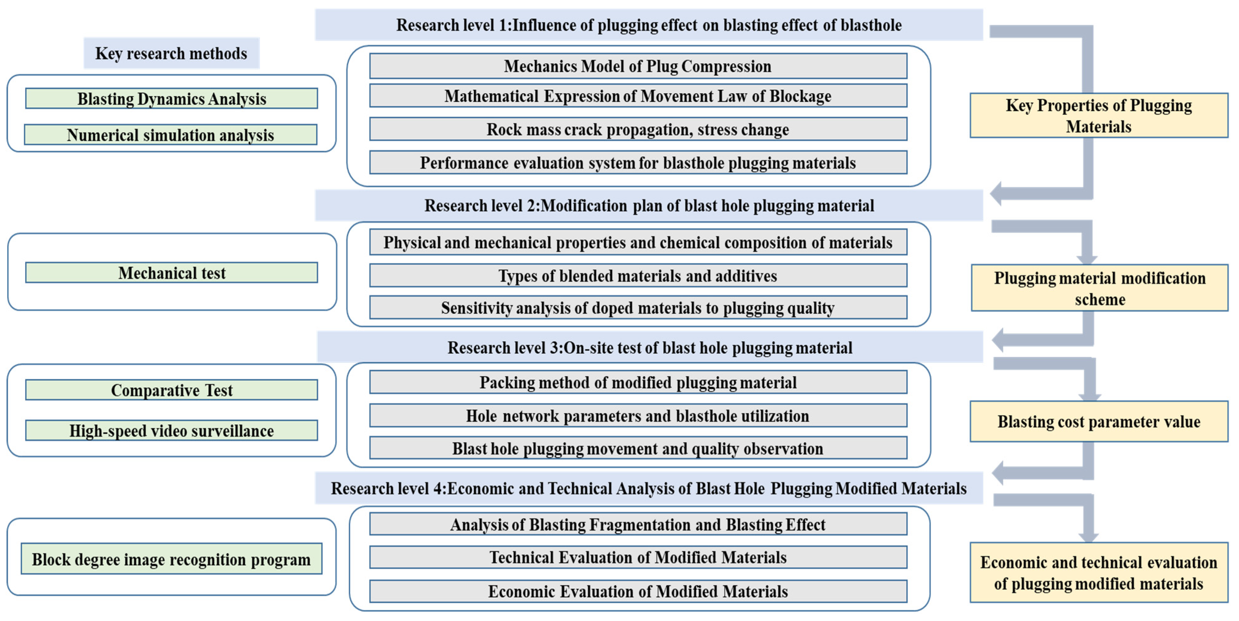
Figure 1. Thesis Framework.
Sustainability 15 04257 g001
Figure 2. Effect of blockage on pressure change in the hole.
Sustainability 15 04257 g002
Figure 3. Blockage material by the action of the blast wave process.
Sustainability 15 04257 g003
Figure 4. Effective stress time curve for different sections of the plug.
Sustainability 15 04257 g004
Figure 5. Force processes on geopolymer specimens.
Sustainability 15 04257 g005
Figure 6. Crushing process of geopolymer specimens.
Sustainability 15 04257 g006
Figure 7. Movement of the plugging material in the hole.
Sustainability 15 04257 g007
Figure 8. The three parts of the blockage body are accelerating, velocity, and displacement along the axial direction of the gun hole.
Sustainability 15 04257 g008
Figure 9. High-speed camera set-up and shooting in open pit mines.
Sustainability 15 04257 g009
Figure 10. The hole blockage punching process.
Sustainability 15 04257 g010
Figure 11. Movement characteristics of the plug material after punching.
Sustainability 15 04257 g011
Figure 12. The hole blockage punching form.
Sustainability 15 04257 g012
Figure 13. Indoor testing of geopolymer-modified plugging materials.
Sustainability 15 04257 g013
Figure 14. Top position and site map of East Open-pit Mine satellite3.3. Design of engineering test parameters for blasting blockage.
Sustainability 15 04257 g014
Figure 15. The hole charging, rock powder, and rock powder clogging modified structure.
Sustainability 15 04257 g015
Figure 16. Blasting site operation construction.
Sustainability 15 04257 g016
Figure 17. Explosion area shell hole arrangement.
Sustainability 15 04257 g017
Figure 18. Burst area blockage effect.
Sustainability 15 04257 g018
Figure 19. Exploding pile of pictures import.
Sustainability 15 04257 g019
Figure 20. Reference size calibration chart.
Sustainability 15 04257 g020
Figure 21. Rock Boundary Demarcation.
Sustainability 15 04257 g021
Figure 22. Screen histogram (cumulative percent size distribution—block size).
Sustainability 15 04257 g022
Table 1. HJC material model.
G/GPaPC/MPaFC/MPaT/MPaK3/GPa
12.85.4616.221.98208
Table 2. High-speed photography parameters.
Exposure TimeCapture Frame RateResolutionLensImage FormatsImage Depth
50015001280 × 860Nikon 35 mmGrayscale images8 bit
Table 3. Parameters of the movement characteristics of the plug material after punching.
Time IntervalCorresponding FrameDisplacement (m)Speed (m/s)Acceleration (m/s2)
049480037.59
1495839.1037.5934.40
24968153.3771.9912.93
34978254.8884.911.25
44988358.4486.1712.28
54998475.6798.456.76
65008612.65105.22−6.56
75018723.5498.65−4.93
85028840.5993.721.67
95038951.7095.39−0.10
1050481075.2295.30−3.28
1150581179.4892.033.33
Table 4. Initial pilot program.
GroupingRock Powder/gSlag/gNaOH Solution (30%)/gWater Glass (Modulus 3.2)/gWater/gMaintenance Time/h
A150015080100806
A250015080100806
A350020040120406
A470015040120406
A570020040140406
A670020040140806
Table 5. Analysis of uniaxial compressive strength results.
GroupCompressive Strength
(MPa)
Average Compressive Strength (MPa)
A310.7911.92
13.10
12.76
10.99
11.94
A513.3412.43
12.51
11.86
12.58
11.85
A615.8216.22
15.29
16.44
15.92
17.62
Table 6. Deep Hole Blasting Parameters.
Hole Diameter
(mm)
Hole Distance
(m)
Row Distance
(m)
Slope Top Line (m)Slope Bottom Line (m)Step Height
(m)
Design Unit Consumption (kg/m3)
250874.5–5.06.514–21.60.46
Average hole depth (m)Over depth (m)Single hole dosage (kg)Total dosage (kg)Packet diameter (mm)Plugging length (m)
18.41.5399–655.284,1802506.0–7.5
Charging structure and descriptionComparison area using porous granular ammonium oil explosives for segmental charging, an overall blockage of 6.0–7.5 m.
Test area using porous granular ammonium oil explosives for segmental charging, the middle air spacer interval of 1 m, blockage using a compound structure, the upper 2 m for geopolymer, the lower 3.5 m for rock powder blockage as shown in Figure 15.
Table 7. Materials for rock powder plugging modification program.
Material NameMain ComponentsTotal Amount of Material/The Hole Per Linear MeterInstructions for Use
Rock powderPowdered sand rock, sandstone and other drilling powder253 kgCalculated by dry density 1.8 g/cm3
SlagSlag powder72 kgOrdinary slag powder
NaOH solution (30%)Sandstone15 kgSelf-assembled
Water glassSodium silicate51 kgModulus 3.5
waterH2O30 kgCommon tap water
Disclaimer/Publisher’s Note: The statements, opinions and data contained in all publications are solely those of the individual author(s) and contributor(s) and not of MDPI and/or the editor(s). MDPI and/or the editor(s) disclaim responsibility for any injury to people or property resulting from any ideas, methods, instructions or products referred to in the content.