Article

An Engineering Case History of the Prevention and Remediation of Sinkholes Induced by Limestone Quarrying

1
State Key Laboratory for Geomechanics and Deep Underground Engineering, China University of Mining and Technology, Xuzhou 221116, China
2
Shenzhen Urban Public Safety and Technology Institute, Shenzhen 518046, China
3
Guangdong Nonferrous Metals Geological Exploration Institute, Guangzhou 510080, China
*
Author to whom correspondence should be addressed.
Sustainability 2023, 15(3), 2808; https://doi.org/10.3390/su15032808
Submission received: 12 January 2023 / Revised: 30 January 2023 / Accepted: 31 January 2023 / Published: 3 February 2023
(This article belongs to the Collection Mine Hazards Identification, Prevention and Control)

Abstract

:
This paper introduces an engineering case history of the prevention and remediation of sinkholes induced by limestone quarrying in Longmen county, Huizhou city, China, through karst groundwater-air pressure monitoring, the design and construction of a grouting curtain, and grouting effect detection. Based on hydrogeological surveys, the location of the main karst development zones and faults can be accurately delineated by combining geophysical exploration with drilling, providing a basis for curtain setting. According to the interpretation results of geophysical exploration, the monitoring boreholes of groundwater-air pressure were set up, which provided support for mine construction, optimization of prevention and remediation of the sinkhole scheme, and reduction of sinkhole risk. In order to prevent the further expansion of sinkhole hazards, grouting curtain technology was used for engineering treatment of the water inflow points of the quarry. After construction of the grouting curtain was completed, comprehensive detection methods were used to evaluate the grouting effect of the curtain. The results showed that the inflow rate reduced from 3500 to approximately 500 m3/day, the water plugging effect was significant, and the occurrence of sinkhole hazards was effectively reduced. The monitoring boreholes can capture the changes of groundwater-air pressure within karst conduit systems, and the purpose of monitoring and warning of sinkholes can be achieved by setting an appropriate warning threshold.

1. Introduction

With the acceleration of urbanization and infrastructure construction, the demand for cement has increased sharply. As the main raw material of cement production, the demand for limestone has also increased synchronously. However, frequent unreasonable open-pit mining activities have destroyed the ecological environment around mines, and sinkholes have become the main geological environment problem linked with mine construction.
In karst areas, the high anisotropy of carbonate rocks means that drilling data are unable to truly reflect the karst development characteristics of the mining area and may lead to the wrong conclusion of hydrogeological conditions [1,2]. When the quarrying operation exposes the karst conduits or fracture zones, it is accompanied by many water inflow phenomena. When the groundwater table is lowered around the mining area, local instability of the soil produces soil caves, which eventually leads to the occurrence of sinkholes and other hazards [3]. Since the 1940s, there have been many sinkhole events induced by limestone quarries, and the affected area changes with the water inflow of the quarry. In May 1949, a limestone quarry in Hershey, Pennsylvania, with an average drainage of 6500 gpm, altered groundwater levels over an area of 10 square miles, and about 100 sinkholes formed in the area [4]. In 1986, a limestone quarry in Valley and Ridge Province was mined to a depth of 60 m below the original groundwater level, resulting in a wide range of groundwater depression cones. The groundwater level at 0.8 km from the quarry was lowered 18 to 24 m, and multiple sinkholes were generated within 1.6 km of the quarry, threatening the operation of local railways [5]. From 1992 to 2008, 353 sinkholes occurred in Chini Village, Huadu District, Guangzhou City, mainly caused by limestone quarrying and large groundwater pumping [6]. Eighty-six sinkholes occurred in the Hejing mining area of Pingnan County, Guangxi Province, China. The zone of dewatering influence was about 9.36 km2, and the maximum influence radius was about 2.1 km [7]. During 2017 and 2018, more than 30 sinkholes formed in an agricultural region that is located adjacent to a limestone quarry in northeast Thailand, which affected the local agricultural activities and power transmission towers [8]. With the increasing demand for cement materials and the expansion of limestone quarries, the occurrence of sinkholes induced by limestone quarrying is becoming increasingly serious.
In order to effectively protect the ecological environment of the mining area and ensure the safe mining of the quarry, a grouting curtain is often used in mine water inflow treatment engineering. The hydraulic connection on both sides of the curtain is cut off by filling the cracks and karst conduits with cement and other materials. Since the 1960s, the curtain grouting technique has been gradually adopted in mine water inflow treatment engineering. This has promoted the development of the curtain technique and grouting theory, with excellent results [9,10]. Cement–sodium silicate, hot bitumen, coal slurry, modified clay, and polyurethane foam mortar are often used as grouting materials for curtains [11]. The curtain technique mainly includes drilling, grouting, and grouting in special strata [12,13,14,15,16]. Determining the grouting effect of a curtain mainly consists of geophysical analysis, verification boreholes, Lugeon tests, pumping tests, and groundwater-air pressure monitoring on both sides of the curtain [17].
At present, the research on sinkhole hazards induced by limestone quarries mainly focuses on the evolution of the groundwater seepage field and engineering treatment methods, while research on the monitoring and warning of sinkhole hazards in limestone quarry is limited. In addition, quarries usually adopt a negative treatment for sinkholes, without considering the change of groundwater dynamic fluctuations during quarrying, and grouting programs to prevent water inflow often use a single method to detect the grouting effect. This paper introduces the prevention and remediation of sinkholes induced by limestone quarrying through a case study, which provides a reference for similar projects in the future.

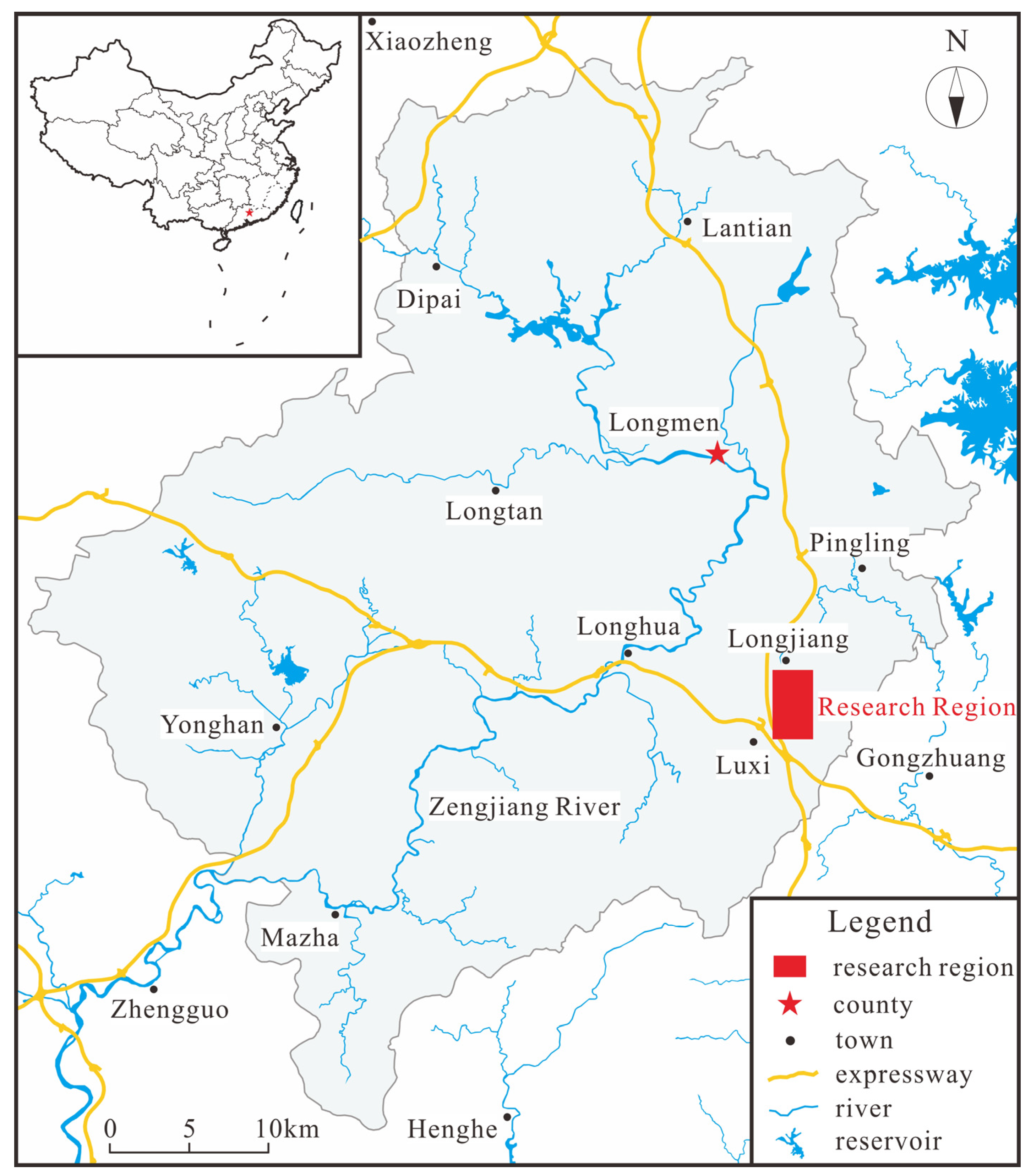
2. Research Background

Longmen County is located in the central part of Guangdong Province, with rich mineral resources, mainly including limestone, lead-zinc, and geothermal resources (Figure 1). Longmen County has Guangda, Huarun, Tapai, and other cement enterprises, and is one of the largest cement production bases in Guangdong Province. In 2020, the annual cement output was 15.5453 million tons, accounting for 83.96% of the annual cement output of Huizhou City. There are many expressways in the territory, which are closely connected with the cities in the Pearl River Delta.
The quarry assessed in this paper is located in Longmen County, Huizhou City, China, where limestone is mined for cement. The mining elevation is +231.4 to −30 m, and the mining area consists of 2.6011 km2. The quarry is divided into north and south pits, which are mined to an elevation of 0 m. The carbonate rocks in the mining area consist of Carboniferous Liujiatang (C1ylj), Shidengzi (C1ds), and Huanglong (C2h) formations. The upper unit (C2h) is thick-layered crystalline dolomite, which is partially intercalated with dolomitic limestone, and the lower unit consists of thick-layered crystal limestone. The lithology of the Shidengzi Formation is mainly in the form of thick-layered argillaceous limestone, thick-layered carbonaceous limestone, thick-layered crystalline limestone, and thin–medium-layered micritic limestone. The exposed thickness is about 276 m, whichias the main stratum with karst development. Additionally, most of the Liujiatang Formation is covered by Quaternary deposits with a thickness of about 120 m. The upper unit (C1ylj) contain medium–thick-layered carbonaceous limestone, bioclastic limestone, dolomitic limestone, and calcareous dolomite. The lower unit is mainly composed of argillaceous limestone, calcareous mudstone, argillaceous siltstone, and siltstone, and is locally intercalated with bioclastic limestone. The mining area is located in the uplift end of the axial NE-trending anticline, and the stratigraphic occurrence changes significantly, mainly due to the NNE-trending fault structures (Figure 2).
In mid-October 2018, in the northeastern corner of the south pit of the quarry, the karst fissure zones accidentally broke through and water inflow occurred at a water inflow rate of about 3500 m3/day. Since 12 November 2018, 17 sinkholes have formed around the mining area, the largest of which is 8 m in diameter and 6 m in depth. Furthermore, many water wells in the nearby village have dried up, and 107 houses have fractured due to mine water inflow (Figure 3). In March 2019, we conducted an emergency investigation, and the results showed that the northeastern corner of the south pit was in the intersection area of faults F1 and F6, and this area was characterized by relatively broken rocks and strong karst development.

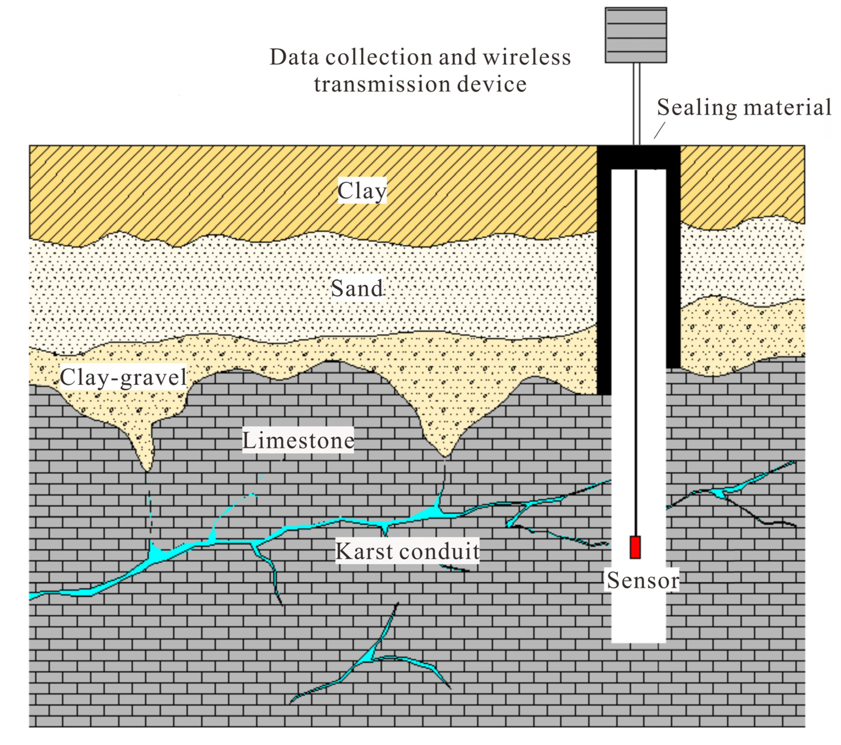
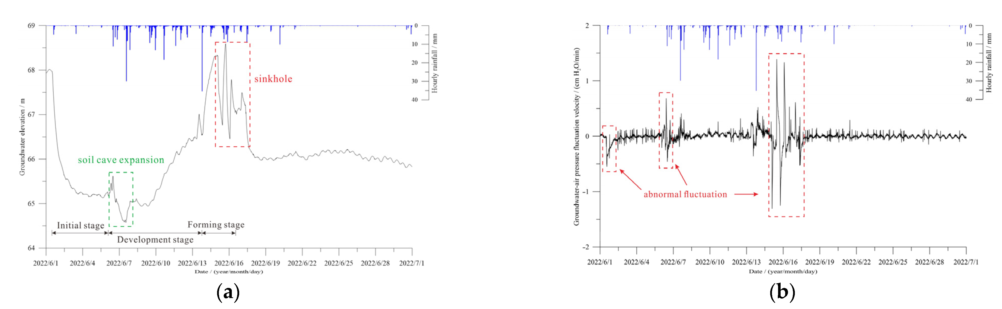
3. Karst Groundwater-Air Pressure Monitoring

When the sinkholes formed around the quarry, the quarry companies often ignored the impact of the changes in the groundwater dynamics on the sinkholes. Jiang and Lei proposed a new technique for groundwater-air pressure monitoring in karst fissures and pipeline systems, which could fully reflect the changes in the groundwater-air pressure in karst pipeline fissure systems, as well as explain the sudden changes in karst groundwater-air pressure, and the reasons for these changes [18].
Through the collection of regional geological data and early drilling information from the site, the stratigraphic lithology, geological structures, and hydrogeological conditions were determined. Furthermore, the depth of the monitoring borehole was determined based on the type of exposed karst aquifer, along with its depth and thickness. The boreholes were designed to pass through the karst fissure zones or karst conduits to monitor the dynamic changes in groundwater-air pressure. After the monitoring borehole was drilled, a steel casing was used to isolate the soil aquifer from the karst aquifer. After the sensor was installed, sealing materials were used to seal the borehole orifice to restore the original geological conditions (Figure 4).
Groundwater-air pressure monitoring boreholes continuously monitored the abnormal fluctuations in groundwater-air pressure at 10-min intervals during the mining process. Figure 5 shows the monitoring results of the groundwater-air pressure of borehole JC28. It can be seen from Figure 5b that the fluctuation velocity of groundwater pressure caused by rainfall was generally less than 0.5 cm/min, which was not significantly different from that without rainfall.
There were three abnormal fluctuations of groundwater-air pressure, and the sinkhole event could be divided into three stages. Initial stage: the quarry uncovered water-filled karst pipes, which led to the rapid decline of the groundwater level, a large difference in groundwater head was generated, and an initial soil cave was formed. Development stage: under the effect of groundwater head difference, the groundwater flow rate increased, and the soil cave gradually expanded, forming a short-term plugging in the karst pipes, causing abnormal fluctuations in the groundwater-air pressure. Forming stage: under the influence of rainfall during the flood season, the groundwater level rose significantly, the soil was saturated and softened, the seepage pressure increased, and the soil was destabilized, resulting in a sinkhole.
Abnormal groundwater-air pressure fluctuations before and during the sinkhole formation could be captured, and the abnormal values were significantly different from the normal fluctuations; in particular, the abnormal groundwater-air pressure fluctuations during the sinkhole formation could reach tens of times the normal fluctuation values. However, the abnormal groundwater-air pressure fluctuations were not clearly reflected in the monitoring curves of sinkhole hazards induced by loading.

4. Design of Grouting Curtain

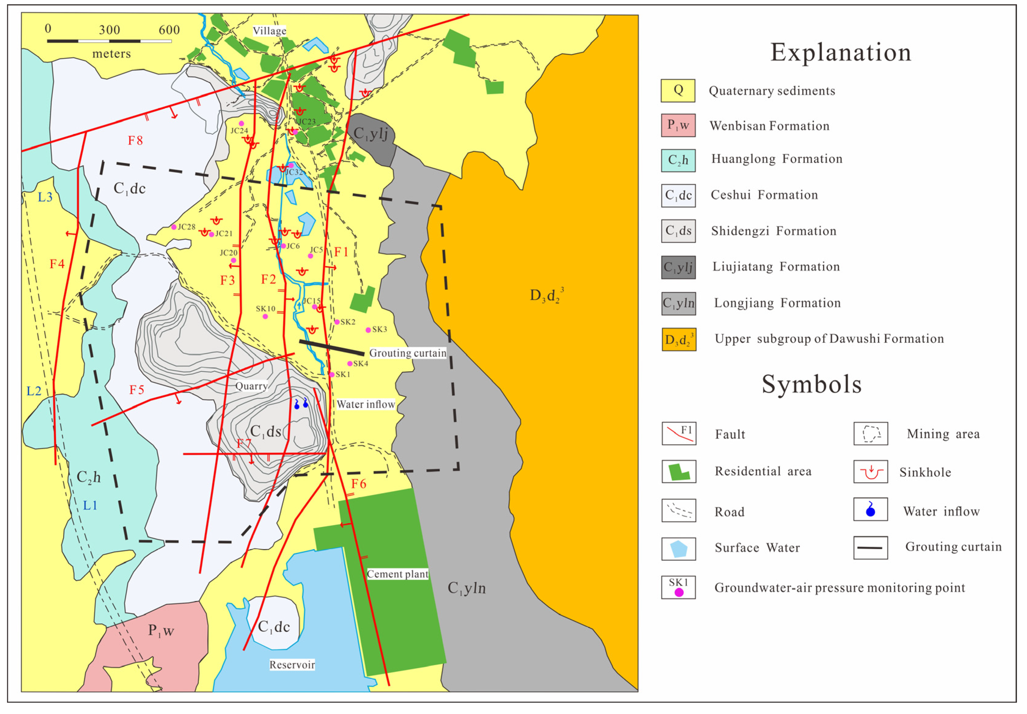
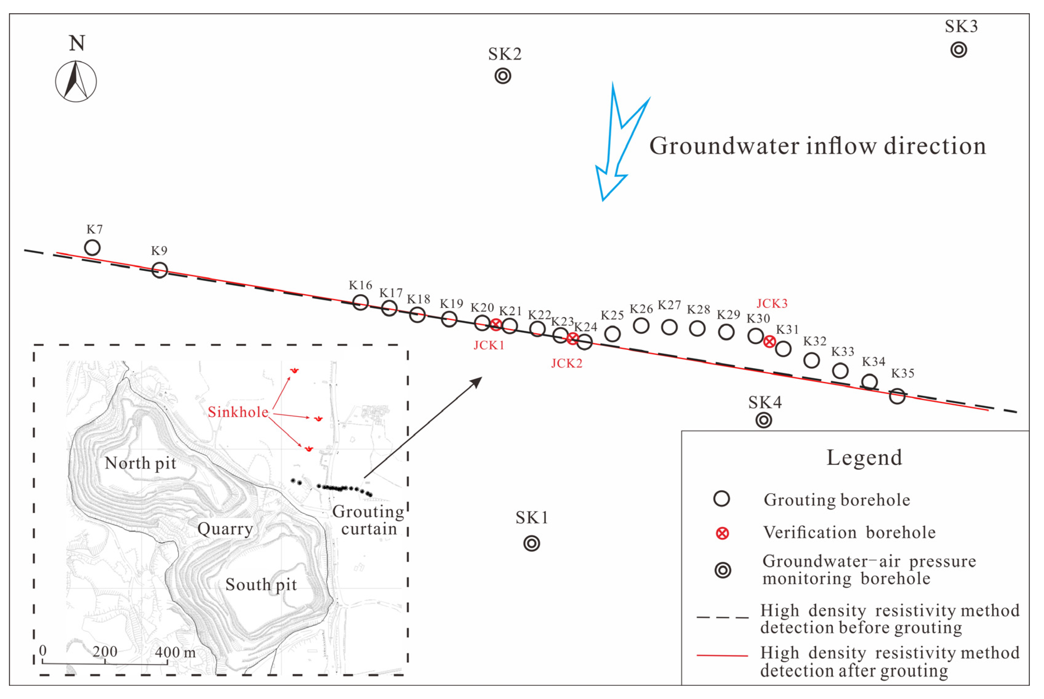
4.1. Location of the Curtain

A grouting curtain was used to seal the groundwater runoff zones at the bottom of the quarry, ensuring the safe mining of the quarry, as well as the safety of the local residents and their property. According to the site survey, the locations of the sinkholes, disappearance of surface water, and house cracks occured in the northern part of the quarry. Thus, the supply sources for the water inflow points could be preliminarily determined. Based on the geophysical test results, and considering the irrigation water of the local residents, the approximate position of the grouting curtain was determined. However, the final location of the curtain was somewhat limited by the terrain, farmland, and houses.
The curtain was constructed perpendicular to the NNE-trending fault, with a length of about 200 m, and the eastern boundary of the curtain was embedded in the sandstone of the Longjiang Formation.

4.2. Grouting Borehole Parameters

A total of 513 sets of borehole data were collected in the study area, and 258 of the boreholes encountered exposed the karst caves (Figure 6). The statistical results of the karst cave development elevation showed that 75% of the karst cave development elevations were between 40 and 70 m, and mainly 20 m below the bedrock surface. The deep karst formations were also mainly developed in the contact zone between the Liujiatang Formation (C1ylj) and the Shidengzi Formation (C1ds).
Considering the development elevation of the karst caves and the fact that the quarry will be mined to an elevation of −20 m at a later stage, the bottom elevation of the grouting boreholes was set to −60 m. The grouting boreholes were designed in a single row, with a spacing of 10 m, with 22 grouting boreholes, and a single borehole depth of about 120–150 m. The opening borehole diameter was 130 mm, and the final borehole diameter was 91–75 mm. The designed slurry radius was also at least 7.07 m, and the solid permeability coefficient was 0.06 m/d, forming a 10 m thick curtain wall.
The karst caves were exposed in grouting boreholes K22, K23, and K24 at roughly the same elevation, and they consisted of filled or semi-filled caves. Water leakage occurred during drilling, and the adjacent boreholes channeled each other during grouting, indicating that the karst caves exposed along the curtain axis were interconnected and were the main runoff zones for groundwater. Additionally, during drilling, two major void zones were discovered. The formations of the west void zones were closely related to the fault position, and the east void zones were developed at the stratigraphic boundary (Figure 7).
Conventional cement grouts were used in the curtain, and the concentration of the slurry was based on the rock permeability obtained from the Lugeon test. The water–cement weight ratios of the grouts were 2:1, 1.5:1, 1:1, and 0.8:1. The additive in the grout was sodium silicate. In order to make the grouts quickly and reduce the influence on the later strength of concrete, the proportion of sodium silicate in the grouts was 1%. Two percent sodium silicate was added in areas requiring large amounts of grouting. The fineness of the cement used for the grouting was such that the sieve allowed for no more than 10% to pass through 80 mm diameter holes. The modulus of the sodium silicate was 2.8–3.4, and the relative density was 1.357–1.453. The grouts were concentrated in the pulping station, pumped to the secondary mixing barrel, and then finally poured into the borehole using a grouting pump.
Once the borehole orifice was closed, the grouts were circulated in the borehole, and the upward and downward directions were connected with segmented grouting. This grouting technique achieved a constant grouting pressure and effectively controlled the diffusion radius of the grouts. The segmented grouting process was conducted as follows. Grouting was carried out after drilling one section, and the next section was drilled after grouting. The above process was conducted in cycles until the designed borehole depth was reached. When large void zones or karst conduits were encountered, the seif−flow grouting method was adopted.
The designed final pressure of the bedrock after grouting was 1.2 MPa, and the curtain grouting was changed by increasing the grout concentrations, step by step. When the injection volume for a certain proportion of grout reached 25 m3, and the grouting pressure did not increase significantly, nor did the injection rate decrease, the grout concentration was increased. If the grouting pressure did not increase significantly when the grout with the largest specific gravity was used, the amount of sodium silicate was increased from 1% to 2%. Thus, intermittent grouting was needed when the grouting pressure still did not increase. The grouting volume of the intermittent grouting was approximately 150 m3, and the intermittent time was generally 8 h.
Therefore, the stopping criteria for segmented grouting met the following two criteria:
(1)
When the grouting pressure increased uniformly and continuously reaching the designed final pressure, and the slurry suction of the borehole was less than 10 L/min, grouting was conducted for 20–30 min.
(2)
After grouting, the Lugeon test was carried out, and the unit permeability was less than 3 lu.

4.3. Implementation of the Data Statistics of the Grouting Curtain

A total of 22 grouting boreholes were used for curtain construction, with a total footage of 2793.28 m. The total thickness of the limestone was 2254.05 m. Nineteen of the boreholes contained karst caves. Thirty-six karst caves were exposed, the total height of the karst caves was 253.08 m, and the average karst rate was 11.23%. The maximum height of the karst cave was 22.5 m, which was exposed in borehole K21, with a maximum karst rate of 37.3%.
This grouting engineering was conducted as an emergency measure to stop the water inflow, and drilling was divided into two sequences for grouting. The total grouting volume of the grouting boreholes was 15,477.46 m3, and the average unit grouting volume was 7.207 m3/m. The statistical results of the grouting in each sequence are presented in Table 1, showing that the unit grouting volume of sequence II was significantly lower than that of sequence I. This indicated that the borehole spacing was reasonable, the slurry was effectively diffused, and the sequence grouting effect was significant.

5. Evaluation of the Grouting Effect of the Curtain

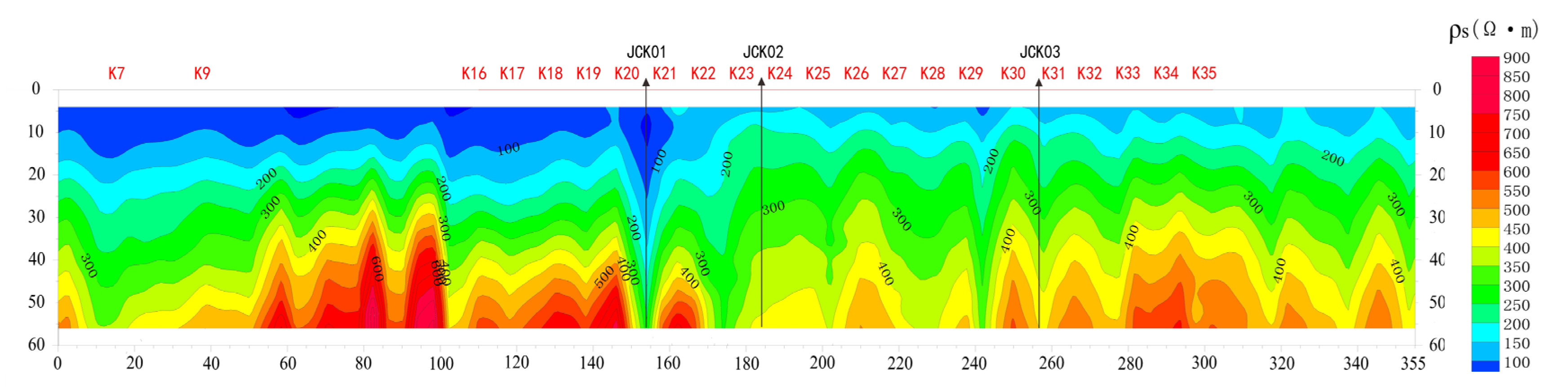
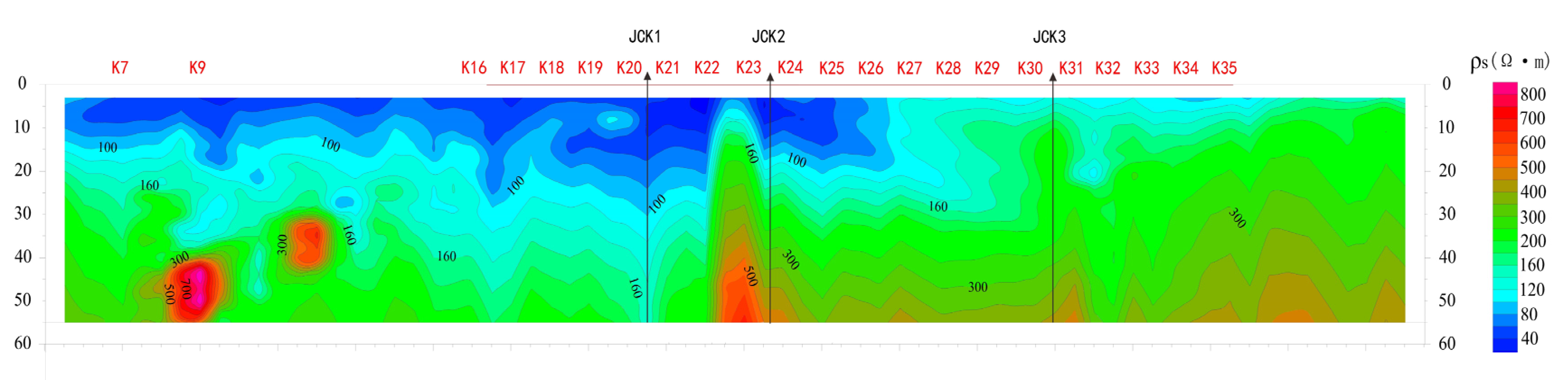
5.1. High-Density Resistivity Method

The high-density resistivity method is based on the differences in electrical conductivity between the rock and the soil, and a stable current field is artificially applied to study the distribution of the conduction current [8,19,20,21]. By comparing the apparent resistivity section maps before and after grouting, it was found that the apparent resistivity of karst development areas after grouting was lower than before grouting. Thus, the apparent resistivity curve of the original low resistivity anomaly in the horizontal direction became flattened (Figure 8, Figure 9 and Figure 10).

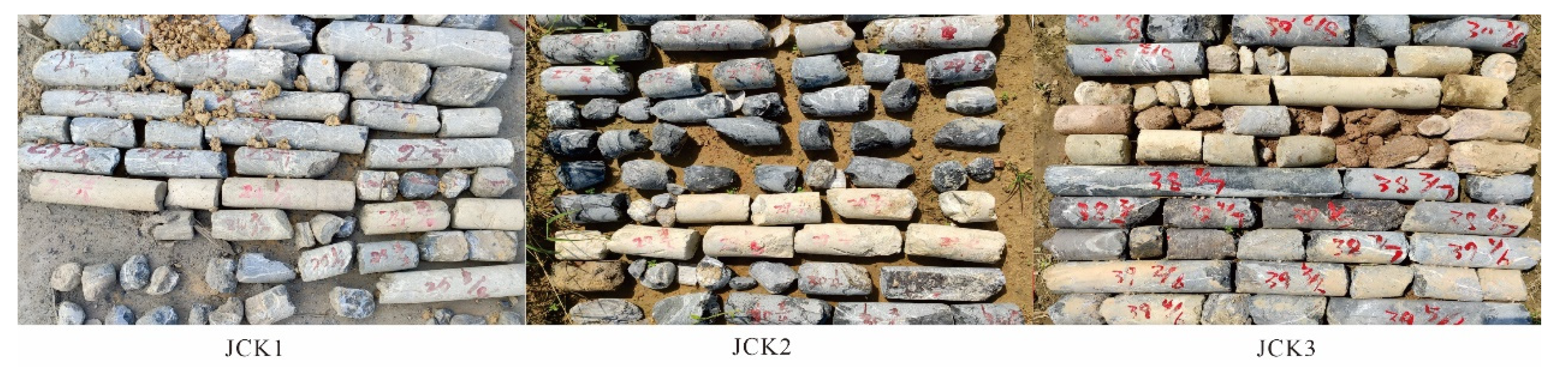
5.2. Verification Boreholes

Verification boreholes are the most direct method of checking the cross-linking state between the grouting boreholes, specifically to check for the presence of permeable cracks and caves, as well as to assess their filling conditions and distribution in the grouting areas. Based on analysis of the sinkhole locations, karst development distribution, grouting amount, and apparent resistivity section maps, verification boreholes JCK1, JCK2, and JCK3 were drilled between grouting boreholes K20 and K21, K23 and K24, and K30 and K31, respectively. According to the photos of the cores from the verification boreholes, cement slurry stones were found in the fracture zones and karst caves at different depths in the boreholes, and a thin layer of cement was found on many fracture surfaces, indicating that the grout filled the void zones effectively (Figure 11).

5.3. Lugeon Test

The Lugeon test uses high pressure to inject water into the borehole to obtain the fracture development and permeable rate of the rock masses based on the water absorption calculation results. The test results provide basic data to evaluate the quality and effect of the grouting curtain. Lugeon tests were carried out in the verification boreholes and the adjacent grouting boreholes.
According to the longitudinal distribution of the permeable rate obtained from the Lugeon tests, the upper rock masses had relatively high permeable rates due to the present of faults, and this was the layer where corrosion cracks and karst caves developed. The permeable rates of the lower rock masses were relatively low, and fractures did not develop, thus allowing it to serve as an aquifuge. The weighted average permeable rates of the verification boreholes were significantly lower than the adjacent grouting boreholes, indicating that the grouts in the grouting areas had a good karst fissure filling effect (Table 2).

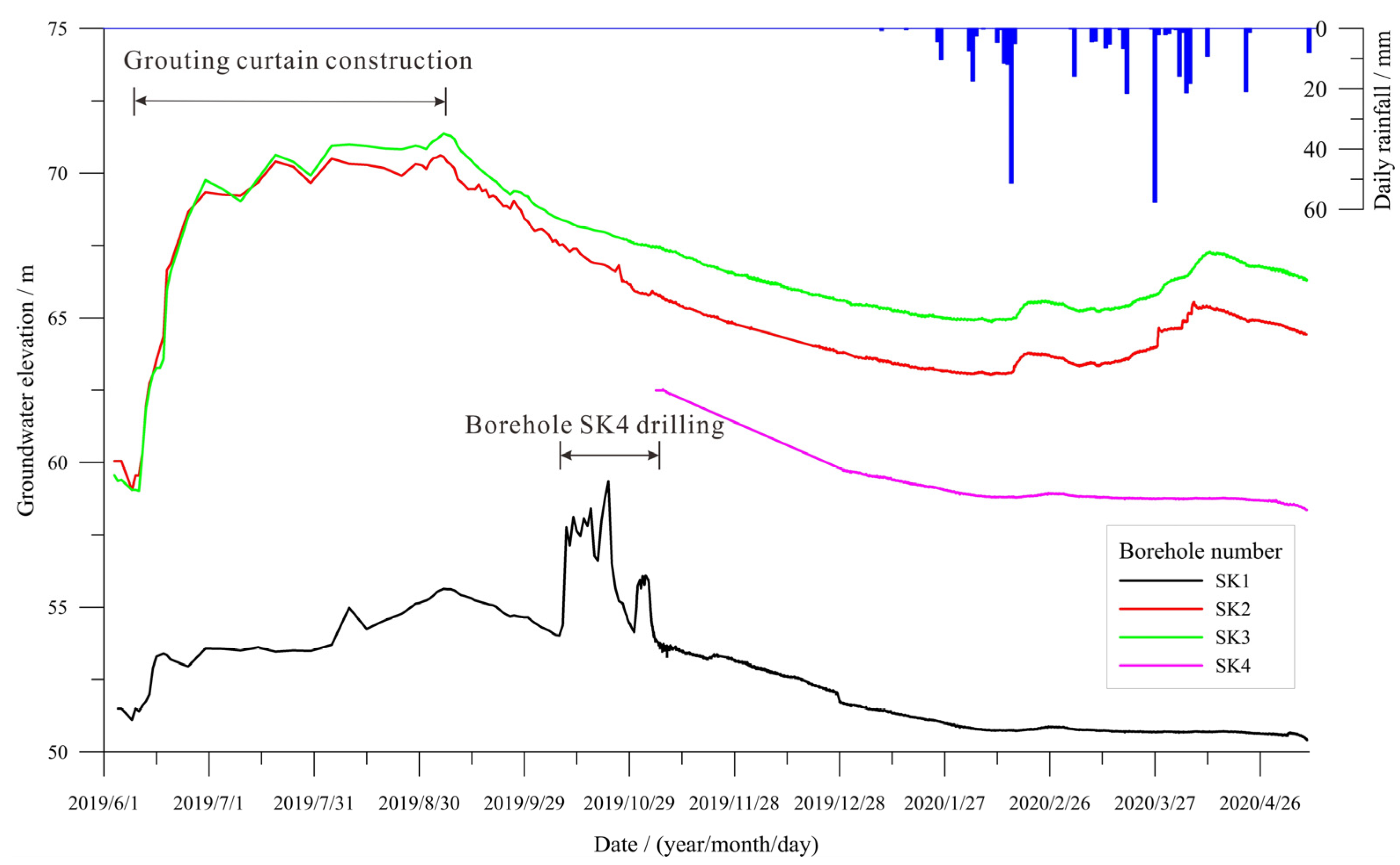
5.4. Groundwater-Air Pressure Monitoring on Both Sides of the Curtain

There were four groundwater-air pressure monitoring points on both sides of the curtain; SK2 and SK3 were located in the northern part of the curtain, while SK1 and SK4 were located in the southern part of the curtain. The monitoring data showed that (Figure 12):
(1)
The groundwater level on both sides of the curtain were obviously different before and after grouting, and the groundwater level on the north side of the curtain was significantly higher than that on the south side. After the curtain grouting was completed, the groundwater level of borehole SK1 rose by 4.2 m, while boreholes SK2 and SK3 rose by 11.2 m and 11.9 m, respectively. The groundwater level difference on both sides of the curtain increased from 8.0 m to 14.9 m.
(2)
The response of the groundwater level on both sides of the curtain to the drilling construction was obviously different. In October 2019, the borehole SK4 drilling construction on the south side of the curtain had a great impact on groundwater; the groundwater level of the adjacent monitoring borehole SK1rose and fell sharply, with a maximum variation of 5.3 m, while the groundwater level at the north side of the curtain was nor disturbed.
(3)
The response of groundwater level on both sides of the curtain to rainfall were obviously different. After being recharged by rainfall infiltration, the recharge range on the north side of the curtain was large, and the groundwater level had risen, while the groundwater level on the south side of the curtain has slowly decreased due to the drainage of the quarry.
Figure 12. Monitoring curves of groundwater level on both sides of the curtain.
Sustainability 15 02808 g012
In summary, the curtain cut off the groundwater runoff channel and changed the groundwater recharge conditions on both sides of the curtain, resulting in different dynamic changes in the groundwater level on both sides of the curtain.

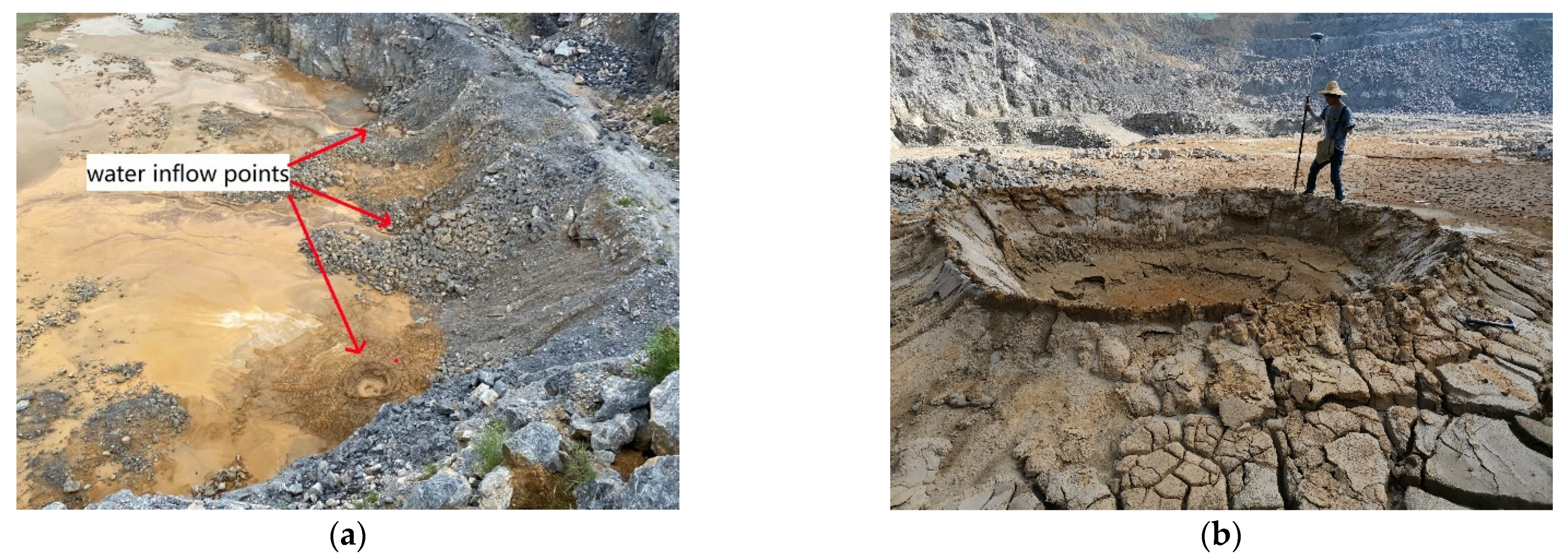
5.5. Water Plugging Effect at Inflow Points

After completion of the curtain, the water channel connected to the main water inflow point was filled with grout, and the soil contained cement slurry (Figure 13). At the remaining two water inflow points, water still flowed out of the fracture flow channels, but the water inflow was reduced from 3500 to 500 m3/day.

6. Discussions

We conducted some seepage deformation tests on the soil of the monitoring borehole and found that the fluctuation velocity of groundwater-air pressure during sinkhole formation has a certain correlation with the critical water flow velocity of soil seepage deformation. We will carry out further research on the direct correlation between these two values, and expect to obtain the setting law of sinkhole monitoring and early warning threshold.

7. Conclusions

The following conclusions were drawn in this paper.
(1)
Groundwater-air pressure monitoring is an effective method for monitoring sinkhole hazards, and can capture the abnormal groundwater-air pressure fluctuations before and during the process of sinkhole formation. The abnormal values of groundwater-air pressure fluctuation velocity can reach tens of times the normal fluctuation values, which can be used as a monitoring index for the monitoring and early warning of sinkhole formation.
(2)
Grouting curtains are an effective means of controlling water inflow in quarries, as they can effectively control the hazards posed by water flowing through fractures during the quarrying process and greatly reduce damage to the surrounding geological environment. After the curtain construction was completed, the grouting effect was checked by the variation of the curve shape of the high-density resistivity method physical property parameters before and after grouting, and the permeability of the curtain could be verified by combining the results of verification boreholes and Lugeon test.
(3)
The evaluation results show that the curtain cut off the groundwater runoff channel and changed the groundwater recharge conditions on both sides of the curtain, resulting in different dynamic changes in the groundwater level on both sides of the curtain; a significant water level difference formed on both sides of the curtain, and the inflow rate reduced from 3500 m3/day to approximately 500 m3/day. However, groundwater will penetrate the karst environment and widen the existing flow paths and create new ones. It is recommended to strengthen groundwater monitoring and make remediation measures based on monitoring results.

Author Contributions

Formal analysis, Z.T.; Investigation, Z.T., L.C., Y.W. and L.G.; Data curation, G.Q.; Writing—original draft, Z.T.; Writing—review & editing, Z.T., L.S. and D.J. All authors have read and agreed to the published version of the manuscript.

Funding

The authors received no financial support for the research, authorship, and/or publication of this article.

Institutional Review Board Statement

Not applicable.

Informed Consent Statement

Not applicable.

Data Availability Statement

The data that support the findings of this study are available from the corresponding author upon reasonable request.

Conflicts of Interest

The authors declare no conflict of interest.

References

  1. Kastning, E.H. Quarrying in Karst: Geotechnical estimation of environmental risk. In Sinkholes and the Engineering and Environmental Impacts of Karst; American Society of Civil Engineers: Reston, VA, USA, 2008; pp. 704–713. [Google Scholar]
  2. Pan, Z.Y.; Jiang, X.Z.; Lei, M.T.; Guan, Z.D.; Gao, Y.L. Mechanism of sinkhole formation during groundwater-level recovery in karst mining area, Dachengqiao, Hunan province, China. Environ. Earth Sci. 2018, 77, 799.1–79910. [Google Scholar] [CrossRef]
  3. Wang, H.; Li, L.; Li, J.P.; Sun, D.A. Drained expansion responses of a cylindrical cavity under biaxial in-situ stresses: Numerical investigation with implementation of anisotropic S-CLAY1 model. Can. Geotech. J. 2022, 60, 198–212. [Google Scholar] [CrossRef]
  4. Foose, R.M. Ground-water behavior in the Hershey Valley, Pennsylvania. Geol. Soc. Am. Bull. 1953, 64, 623–645. [Google Scholar] [CrossRef]
  5. Kath, R.L.; Mcclean, A.T.; Sullivan, W.R.; Humphries, R.W. Engineering impacts of karst: Three engineering case studies in Cambrian and Ordovician carbonates of the Valley and Ridge Province. Int. J. Rock Mech. Min. Sci. Geomech. Abstr. 1996, 33, 85A. [Google Scholar]
  6. Luo, R.; Zheng, X.Z.; Yi, S.M. Current situation and prevention of karst surface-collapse geological disaster in Guangzhou Huadu district. Chin. J. Geol. Hazard Control. 2012, 23, 72–75. [Google Scholar]
  7. Li, T.Y. The Research on the Karstic Water Control of Depression Pits. Ph.D. Thesis, Guangxi University, Nanning, China, 2016. [Google Scholar]
  8. Arjwech, R.; Ruansorn, T.; Schulmeister, M.; Everett, M.E.; Thitimakorn, T.; Pondthai, P.; Somchat, K. Protection of electricity transmission infrastructure from sinkhole hazard based on electrical resistivity tomography. Eng. Geol. 2021, 293, 106318. [Google Scholar] [CrossRef]
  9. Burston, M.R.; Memon, B.A.; Green, D.S. Reducing Conduit Water Flow into a Quarry in North-Central Alabama: A Case Study. In Sinkholes and the Engineering and Environmental Impacts of Karst; American Society of Civil Engineers: Reston, VA, USA, 2008; pp. 640–647. [Google Scholar]
  10. Han, W.W.; Li, S.C.; Zhang, Q.S.; Zhang, X.; Liu, R.T.; Zhang, W.J.e. A comprehensive analysis method for searching weak zones of grouting curtain in mines. Chin. J. Rock Mech. Eng. 2013, 32, 512–519. [Google Scholar]
  11. Gao, X.T. High Impermeability Composite Curtain Grouting Scheme and Permeability Detection Method. Mod. Min. 2020, 36, 223–225. [Google Scholar]
  12. Wang, J. A New Technology of Groundwater Flow Cut off by Grout Curtain for Karst Mineral Deposit. Min. Res. Dev. S 2006, 1, 151–153. [Google Scholar]
  13. Yang, Q.; Gao, G.F.; Han, G.L.; Yao, H.M. Study on Construction Technology of Mine Curtain Grouting for Cave Formation. Explor. Eng. (Rock Soil Drill. Tunn.) 2010, 37, 67–69. [Google Scholar]
  14. Sun, K.G.; Li, S.C.; Xu, W.P.; Gong, L. On Grouting Techniques for Preventing Water Inflows in Karst Tunnels. Mod. Tunn. Technol. 2015, 52, 178–183. [Google Scholar]
  15. Yang, Z.; Zhao, Q.; Huang, B.R. Grouting Control Technology and Engineering Application of Strong Dynamic Channel of Mine Curtain. Min. Res. Dev. 2020, 40, 117–121. [Google Scholar]
  16. Shao, W.; Sun, Q.X.; Xu, X.; Yue, W.H.; Shi, D.D. Durability life prediction and horizontal bearing characteristics of CFRP composite piles in marine environments. Constr. Build. Mater. 2023, 367, 130116. [Google Scholar] [CrossRef]
  17. Wei, H.M.; Li, X.; Sun, B.T.; Zhou, S.; Niu, J. Exploration and analysis of geophysical methods in curtain grouting water control. Geophys. Geochem. Explor. 2021, 45, 245–251. [Google Scholar]
  18. Jiang, X.Z.; Lei, M.T. Monitoring technique and its application of karst groundwater-air pressure in karst collapse. Carsologica Sin. 2018, 37, 786–791. [Google Scholar]
  19. Dong, H.B.; Wang, C.L. Development and application of 2D resistivity imaging surveys. Earth Sci. Front. 2003, 10, 171–176. [Google Scholar]
  20. Ezersky, M.G.; Eppelbaum, L.V.; Al-Zoubi, A.; Keydar, S.; Abueladas, A.; Akkawi, E.; Medvedev, B. Geophysical prediction and following development sinkholes in two Dead Sea areas, Israel and Jordan. Environ. Earth Sci. 2013, 70, 1463–1478. [Google Scholar] [CrossRef]
  21. Satitpittakul, A.; Vachiratienchai, C.; Siripunvaraporn, W. Factors influencing cavity detection in Karst terrain on two-dimensional (2-D) direct current (DC) resistivity survey: A case study from the western part of Thailand. Eng. Geol. 2013, 152, 162–171. [Google Scholar] [CrossRef]
Figure 1. Geographic location of Longmen County.
Sustainability 15 02808 g001
Figure 2. Geologic map of the mining area.
Sustainability 15 02808 g002
Figure 3. Sinkhole caused by mine water inflow.
Sustainability 15 02808 g003
Figure 4. Technique for monitoring the karst groundwater-air pressure.
Sustainability 15 02808 g004
Figure 5. Groundwater-air pressure monitoring curve of borehole JC28. (a) Groundwater elevation curve of borehole JC28. (b) Groundwater-air pressure fluctuation velocity curve of borehole JC28.
Sustainability 15 02808 g005
Figure 6. Development elevation of the karst caves.
Sustainability 15 02808 g006
Figure 7. Profile of grouting curtain.
Sustainability 15 02808 g007
Figure 8. Location of boreholes and survey line for high-density resistivity method.
Sustainability 15 02808 g008
Figure 9. Apparent resistivity section map before grouting.
Sustainability 15 02808 g009
Figure 10. Apparent resistivity section map after grouting.
Sustainability 15 02808 g010
Figure 11. Photos of the cores from the verification boreholes.
Sustainability 15 02808 g011
Figure 13. Photos of water inflow points in different periods. (a) Photo of water inflow points exposed after pumping in mining pit. (b) Photo of main water inflow point after grouting.
Sustainability 15 02808 g013
Table 1. Statistical results of the grouting volume.
SequenceNumber of Grouted SectionsGrouting Length (m)Statistical DataElevation Distribution (m)AUGV (m3/m)
< 6060–4040–2020–00–−20−20–−40>−40
I611206.81AUGV (m3/m)4.913.599.2411.8510.389.465.118.521
Grouting length (m)44.93175.03220220220193.25133.6
II56940.75AUGV (m3/m)1.863.084.644.348.019.070.155.521
Grouting length (m)28.7165.9180180180172.6533.5
Total1172147.56AUGV (m3/m)3.723.347.178.479.319.284.127.207
Grouting length (m)73.626340.93400400400365.9167.101
AUGV refers to the average unit grouting volume.
Table 2. Lugeon test results of boreholes.
Verification
Borehole
Burial Depth of Test Section (m)q
(Lu)
q ¯
(Lu)
Grouting
Borehole
Burial Depth of Test Section (m)q
(Lu)
q ¯
(Lu)
JCK129.00–60.002.4452.170K1920.50–40.0061.93920.114
40.00–52.3030.700
60.00–80.002.53452.30–60.5043.089
59.00–82.0011.008
80.00–100.002.30382.00–110.002.770
112.00–137.033.632
100.00–120.001.940K2029.60–45.00128.56325.847
45.00–80.0017.841
120.00–142.951.56780.00–100.008.436
100.00–138.971.383
JCK232.00–60.001.7171.481K2340.00–47.2017.8456.980
47.20–63.0021.408
60.00–80.001.90563.00–71.006.262
71.00–100.002.936
80.00–100.001.933100.00–120.002.739
120.00–140.742.238
100.00–120.001.722K2440.00–59.0019.3905.175
59.00–76.002.757
120.00–140.740.78376.00–100.004.190
100.00–141.670.247
JCK329.60–47.004.8142.643K3025.00–45.0029.4508.915
45.00–60.002.817
47.00–67.003.96260.00–91.000.878
90.00–120.2014.309
67.00~87.002.178120.00–149.770.729
K3132.70–60.003.4573.637
87.00~107.002.71060.00–91.001.239
91.00–106.0012.024
107.00~125.830.722102.00–126.131.104
q refers to the permeable rate, and q ¯ refers to the weighted average permeable rate.
Disclaimer/Publisher’s Note: The statements, opinions and data contained in all publications are solely those of the individual author(s) and contributor(s) and not of MDPI and/or the editor(s). MDPI and/or the editor(s) disclaim responsibility for any injury to people or property resulting from any ideas, methods, instructions or products referred to in the content.

