Review

A State-of-the-Art Review and Numerical Study of Reinforced Expansive Soil with Granular Anchor Piles and Helical Piles

Department of Structural and Geotechnical Engineering, Széchenyi István University, 9026 Győr, Hungary
*
Author to whom correspondence should be addressed.
Sustainability 2023, 15(3), 2802; https://doi.org/10.3390/su15032802
Submission received: 18 December 2022 / Revised: 28 January 2023 / Accepted: 31 January 2023 / Published: 3 February 2023
(This article belongs to the Special Issue Advancing Sustainability in Geotechnical Engineering)

Abstract

:
Expansive soils exist in many countries worldwide, and their characteristics make them exceedingly difficult to engineer. Due to its significant swelling and shrinkage characteristics, expansive soil defies many of the stabilization solutions available to engineers. Differential heave or settlement occurs when expansive soil swells or shrinks, causing severe damage to foundations, buildings, roadways, and retaining structures. In such soils, it is necessary to construct a foundation that avoids the adverse effects of settlement. As a result, building the structure’s foundations on expansive soil necessitates special consideration. Helical piles provide resistance to uplift in light structures. However, they may not fully stabilize foundations in expansive soils. A granular anchor pile is another anchor technique that may provide the necessary resistance to uplift in expansive soils using simpler methods. This review and numerical study investigate the fundamental foundation treatments for expansive soils and the behavior of granular anchors and helical piles. Results indicate that granular anchor piles performed better than helical piles for uplift and settlement performance. For heave performance, the granular anchor and helical piles perform nearly identically. Both achieve heave reductions greater than 90% when L/H > 1.5 and D = 0.6 m.

1. Introduction

Expansive soil is a problematic soil that damages civil engineering structures worldwide [1]. Earthquakes, expansive soils, landslides, hurricanes, tornadoes, and floods are the six most dangerous natural hazards, according to Baer [2], with expansive soils tied for second place with hurricane wind/storm surge in terms of economic losses to buildings. During periods of excessive moisture, expansive soil swells, causing a structure to heave. Expansive soil shrinks when soil moisture decreases, leading to construction settlement [3]. Expansive soil can also create lateral displacement by applying pressure to the vertical face of a foundation, basement, or retaining wall. According to Bowles [4], McOmber and Thompson [5], Nelson et al. [6], and Walsh et al. [7], the soil expands and shrinks in a zone ranging in depth from one meter to more than 20 m below the ground surface. This zone comprises the depth of seasonal variation in moisture; thus, structural damage is due to volumetric changes here, commonly referred to as the “active” or “unstable” zone [8,9]. If volume changes in the active zone of expansive soils occur near a foundation, they cause structural damage. Expansive soil swells excessively when wet and shrinks excessively when dry. Without warning, it may generate large fissures at the surface; the fissures can be 20 cm wide and 4 m deep [10].
As previously stated, swelling soils cause large-scale damage to civil engineering structures due to volumetric increases accompanied by a loss of strength during wet seasons and shrinking during summer [11]. Buildings crack, roads become rutted, and retaining structures deteriorate [12]. These soils are found in almost every country worldwide and challenge geotechnical engineers everywhere [13].
Some researchers have worked on improving soil behavior with special additives [14,15,16,17,18,19]. Others studied the benefits of alternative foundations, especially deep foundations, to resist the damaging effects of expansive soil [20,21,22,23,24,25]. The Department of the Army [26] highlighted the importance of foundations in expansive soils. It recommended choosing cost-effective foundations to minimize structural distress and differential movement between structural elements.
Helical and granular anchor piles are two types of deep foundations used at a construction site to support and stabilize structures. They are frequently employed when conventional foundation techniques, like deep concrete foundations, are neither feasible nor practical [27]. The helical and granular anchor piles have proven their effectiveness in cohesive [28,29,30,31] and cohesionless soils [32,33,34,35,36,37]. They are economical, quick to install [27], and environmentally friendly, as they do not pollute the soil or water [38,39]. Furthermore, as shown in Table 1, helical and granular anchor piles provide pullout resistance in a variety of practical applications that are primarily exposed to tensile loads [34,40,41,42].
Moreover, helical and granular anchor piles are viable alternatives to traditional anchoring methods. Granular anchor pile installation is low-cost and does not necessitate sophisticated equipment [27,37]. Comparing granular anchor piles to a commonly accepted practice, such as helical piles, can be useful in identifying the position of the granular anchor piles within the broad spectrum of anchoring methods [37].
Numerical and experimental studies have demonstrated the behavior of helical [43,44,45,46,47,48,49,50] and granular anchor piles [25,32,51,52,53,54]. However, studies have not examined their anchoring capabilities in expansive soil [55]. Furthermore, the studies did not emphasize comparative studies of the two types of expansive soils.
This study reviews the behavior of both types of piles in expansive soils, followed by a numerical comparison using the PLAXIS 3D software. The primary objectives of this work are to (1) review popular solutions for mitigating the adverse effects of expansive soils on engineering facilities, (2) review research on the behavior of helical piles and granular anchor piles in expansive soils, and (3) compare the granular anchor piles to helical piles based on (2) with the help of numerical modeling using PLAXIS 3D.

2. Research Method

To fully grasp the topic, we applied a mixed review technique and numerical study to assess the performance of traditional and special foundations in expansive soil [56] by:
  • surveying the database and selecting keywords,
  • assembling and screening relevant papers,
  • comparing the different foundations and identifying research gaps,
  • applying numerical modeling to compare helical and granular anchor piles.
Section 7.1.2 discusses numerical modeling methodology in detail.

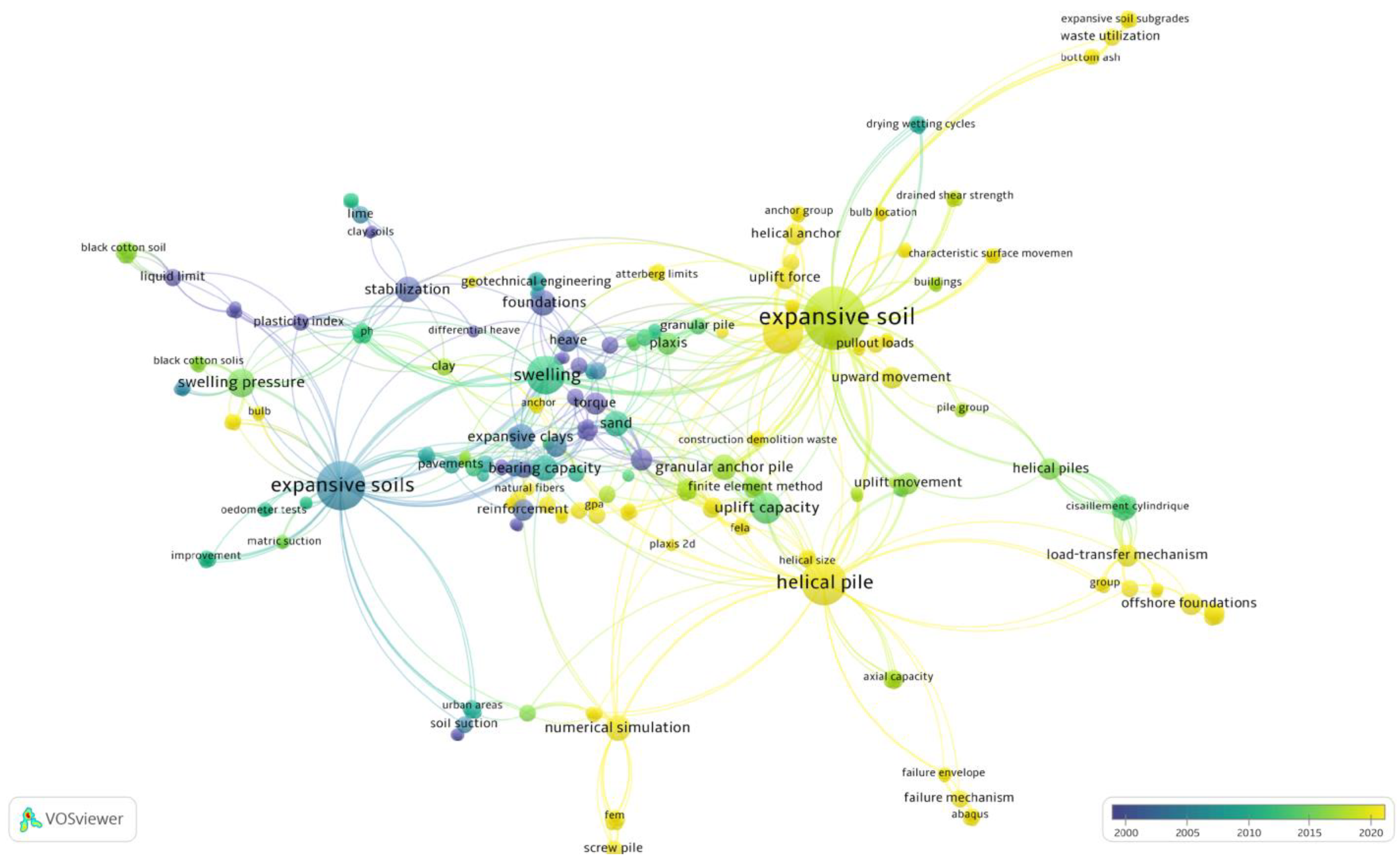
Surveying the Databases and Keywords

All documents were searched, including journal articles, books, conference papers, and proceedings. The most relevant reports were found in three literature databases: Google Scholar, Web of Science (WoS), and Scopus.
Figure 1 depicts the keywords of the existing knowledge domain in the foundations on expansive soil using VOSviewer. The VOSviewer displays the keyword network as a distance-based representation. Each keyword represents a node in this network, and links provide the connections. The distance between two nodes determines the strength or weakness of a relationship. A greater distance indicates a weaker link between keywords, whereas a smaller distance implies a stronger link [57]. The link strength of a node relates to the sum of all the connection strengths attached to it. The different colors represent different research years, and the size of the nodes generated refers to the number of publications where the phrase was first used [57]. Our findings will be highlighted in the following sections, which compare the types and suitability of foundations and primary building solutions for expansive soils and deep foundations. We will focus on the behavior of helical and granular anchor piles and their role in reducing heave.

3. Field Identification of Expansive Soil

Soil type identification in the field usually requires determining the index properties of the soil, such as color, texture, and plasticity, without requiring special equipment. Engineers can modify expansive soils’ behavior by mechanical, thermal, chemical, and other means. As a result, it is essential to investigate expansive soil’s physical and engineering properties, primarily when it is used as a construction material or for foundation purposes.
Adem and Vanapalli [58] observed that swelling soils exhibit surface fissures. They may absorb considerable amounts of water through the fissures during rainfall or local site alterations (such as water pipe, sewer, or storm drain leakage). The added moisture creates a soft, heavy, and sticky clay. The clays can shrink and stiffen as they dry, resulting in ground shrinkage (volume reduction) and cracking.
Various classification methods in the laboratory evaluate index properties that infer expansive soil behavior. Typical tests include Atterberg limits and clay size percent to classify a soil’s expansion potential as low, medium, high, or extremely high. Soils classified as CH or CL in the USCS or A-6 or A-7 in the AASHTO classification systems are considered expansive soils in general [59].
Holtz and Kovacs [60] proposed three essential components to identify swelling damage to structures:
  • The soil contains montmorillonite (a highly active mineral with a high swelling potential found in clay).
  • The natural water content of the soil is close to its plastic limit.
  • A source of water is available for potentially swelling soil.
Expansive soils are classified using a variety of systems. In Table 2, Bowels [4] summarized the findings of Holtz [61] and Dakshanamurthy and Raman [62] to classify the swelling potential of expansive soils. Table 2 shows the potential changes in soil volume as a function of the liquid limit (LL) and the plasticity index (PI).
AASHTO [63] specifies a method that determines whether the soil is expansive and predicts the magnitude of swelling. The soil’s Atterberg Limits correlate to the natural soil suction during construction, as shown in Table 3.
Consequently, a comprehensive foundation design in expansive soils requires a site-specific geotechnical investigation with specialized laboratory testing to identify the index properties (Atterberg limits, moisture content, soil suction), swelling potential, and swelling pressure (e.g., ASTM D4546 [64]). According to Chen [65], the last test is the most important and reliable one for evaluating expansive soils.

4. Types and Suitability of Foundations

There are two types of foundations: shallow foundations (individual [isolated] or combined footing, strip, stiffened mat) and deep foundations (drilled pier, helical piles, granular anchor piles).
According to Jones and Jefferson [66], the principal types of foundations utilized in expansive soils worldwide include pile and beam or pier and beam systems (Figure 2), reinforced rafts, and modified continuous perimeter spread footings, summarized in Table 4.
In low-swelling soils (PI < 15), standard shallow foundations are frequently used [26] when the footing angular rotation (deflection/span length) ratios (Δ/L) are 1/600 to 1/1000 or the differential movement <1 cm.
Stiffened mat foundations (Figure 3) will support buildings in expansive soil (PI ≥ 15), where the expected differential movement could be as high as 10 cm. The mats’ stiffening beams considerably reduce differential distortion [26]. Table 5 displays the beam spacing and depth according to the type of mat.
If appropriately designed and erected, a pile or beam-on-a-drilled-shaft foundation will adapt to a wide range of soil conditions and tend to reduce the effects of heaving soil. Deep foundations can support nearly any superstructure with low differential soil movement. They can achieve shaft deflection/spacing ratios of less than 1/600 [26].

5. Fundamental Building Solutions for Expansive Soils

First, this section briefly presents the basic problem-solving methods for expansive soil foundations. Then it addresses using deep foundations to resolve expansive soil problems that are more complex.
Peck et al. [67]; Bowels [4]; Murphy [68]; and Zumrawi et al. [69] suggest three main techniques to prevent structural damage to newly constructed structures caused by expansive soils.

5.1. Reduce or Prevent Swelling

There are three methods to reduce or prevent swelling in soil:
  • Removing and replacing the expansive soil: If the layer of moderately expansive soil is immediately below the foundation, remove it and replace it with improved soil. When correctly compacted, the replacement layer will distribute loads better and reduce the adverse effects of swelling on the foundation (Lytton et al. [70]; Rao et al. [71]; Murthy and Praveen [72]; Walsh et al. [73]; Ahmed [74]; Srinivas [75]). The effectiveness of the removal and replacement method depends on the thickness and soil type of the replacement layer. A thin, impervious cap may prevent surface water infiltration into the underlying expansive clay. In contrast, a granular replacement layer may encourage deeper wetting of the remaining expansive soil.
  • Changing the soil’s characteristics: Gromko [76] provides several ways to reduce, if not eliminate, heave in expansive soils. Economics and workability will dictate the selection of one of the following strategies:
    • Controlling the level of compactness: Gromko [76] concurs that maintaining the degree of compactness is one of the most practical and cost-effective ways to reduce heave in expansive soil. A soil’s swelling potential diminishes when compacted on the high side, possibly 3–4% above the optimum moisture content. However, in cases where the overall heave exceeds 35 mm, a slab on grade will not perform well.
    • Stabilization through chemicals: Chemical stabilization of expansive soil with various stabilizers, such as fly ash, lime, or cement, has dramatically minimized heave; however, contractors use lime stabilization more than any other chemical agent to stabilize expansive soil. Mixing 4% to 8% lime with plastic clay reduces the plasticity index of the topsoil layer while increasing its load-bearing capacity (Gromko [76]; O’Neill and Poormoayed [77]; Bowels [4]; Prusinski and Bhattacharja [78]; Moayed et al. [79]; Belabbaci et al. [80]; AL-TAIE et al. [81]; and Mahedi et al. [82]).
    • Pre-moistening of expansive soil: pre-moistening is another method for increasing the soil moisture content by immersing an area in water. Jeyapalan et al. [83] stated that submerging the expansive soil in water before building attains most of the estimated heave. Slow water seepage through highly plastic soil, on the other hand, may make this time-consuming. A 10–15 cm thick layer of sand, coarse gravel, or granular soil on top of the area will, according to Gromko [76], provide the contractor with an excellent working surface during and after pre-moistening. This layer reduces evaporation, adds a minor surcharge, and creates a level, uniform subgrade.
  • Controlling the soil’s water content: One of the most effective ways to minimize the heave of expansive soil is to manage its moisture content. Moisture control technologies applied around the perimeter of structures will reduce wetting or drying under the foundation. Impermeable barriers (such as retaining walls and geotextile membranes), proper drainage systems, and vegetation control will maintain moisture levels [76,77,84]).

5.2. Creating a Flexible Building Style and Designing a Resilient Foundation System

Allowing the soil to swell within cavities built into the foundation’s base (the waffle slab, Figure 4) allows a flexible building style with a robust and stiff foundation system. According to Chen [65], this method has been tested in limited cases in the Denver area with mixed results. Helical or granular anchor piles can be used to support this system.

5.3. Isolating the Structure from the Expansive Soil Environment

Short piers or piles lift suspended floor slabs above the active zone of swelling (Figure 5). The harmful movement will not reach the floor slab, keeping the structure intact. Support beams and piers combine to provide an effective foundation system. Deep foundation alternatives appear in the following sections.

6. Deep Foundations in Expansive Soils

Deep foundations transfer structural loads to competent soils well below the ground surface. They may gradually transfer loads into the soil with depth through skin friction or rely on a hard-bearing stratum at their base. For large buildings, deep foundations resist uplift and overturning during strong winds or earthquakes. Pile foundations also limit settlement and effectively resist lifting forces from expansive soils.
Once below the active moisture zone (Figure 5), expansive soils offer moderate strength and do not contain free water. They become suitable materials for driving or drilling piles. As a result, designers often consider deep foundations as an option. Deep foundations provide an attractive solution when a structure requires minimal settlement or resilient support. This review examines two very effective methods to offer the advantages of deep foundations at a low cost (i.e., helical and granular anchor piles). Large areas such as highways are prohibitively expensive, and cut-off walls or shoulder dressings are a better alternative (Dafalla and Shamrani [85]). In some cases, with extremely high swell potential, expansive soil treatment with cement and lime or partial soil replacement is unavoidable.
Table 6 presents the most popular types of pile foundations. The installation impact provides a simple grouping for piles, i.e., displacement, small displacement, and non-displacement. The three levels of displacement refer to the soil that lies in the path of the installation. Displacement piles push the soil aside as they thrust into the ground. Small displacement piles are hollow or have a thin cross-section, so they deflect a smaller volume of soil during installation. Non-displacement piles remove soil from their path so that the neighboring soil remains undisturbed. Sorochan [86] states that in-situ cast piles work best because driving or vibrating piles may cause further difficulties. Helical and granular anchor piles create little to no soil displacement during installation. They are uniquely suited to expansive soils, as discussed in the following sections.

6.1. Granular Anchor Pile

A granular anchor pile is a relatively new foundation technology for reducing expansive clay heave and enhancing foundation performance [87,88]. It is a variation on the traditional granular pile where an anchor carries a tensile load. The pile concept (Figure 6) uses the lower clay as an anchor point. As the expansive clay tries to lift the foundation, the inner rod feels tension (T). The lower granular column gains traction through friction against the (non-expanding) clay. Additional lateral stresses contribute to the sand’s strength throughout [89].

6.1.1. Granular Anchor Pile Installation

Borehole preparation consists of drilling and casing to prevent surrounding soil from entering the hole. Next, insert a mild steel anchor rod with one end connected to the anchor plate into the borehole, resting at the bottom. Finally, fill it with granular material and compact it inside the borehole. A well-graded blend of locally available crushed stone aggregate and sand is typically employed. The filling-compacting process proceeds in layers where compaction effort produces uniform density [52].

6.1.2. Previous Research on Granular Anchor Piles

Rao et al. [89] and Phanikumar et al. [90] reported the results of a field-scale test program evaluating the pullout behavior of granular anchor piles buried in expansive clay beds. The compacted clay bed held single piles with 100, 150, and 200 mm diameters and lengths of 500, 750, and 1000 mm. Preparation of the clay included compaction at 15% moisture content (optimum = 27%), then installing the test pile, followed by water inundation and heaving. Researchers also investigated one group configuration to evaluate its effectiveness. They found:
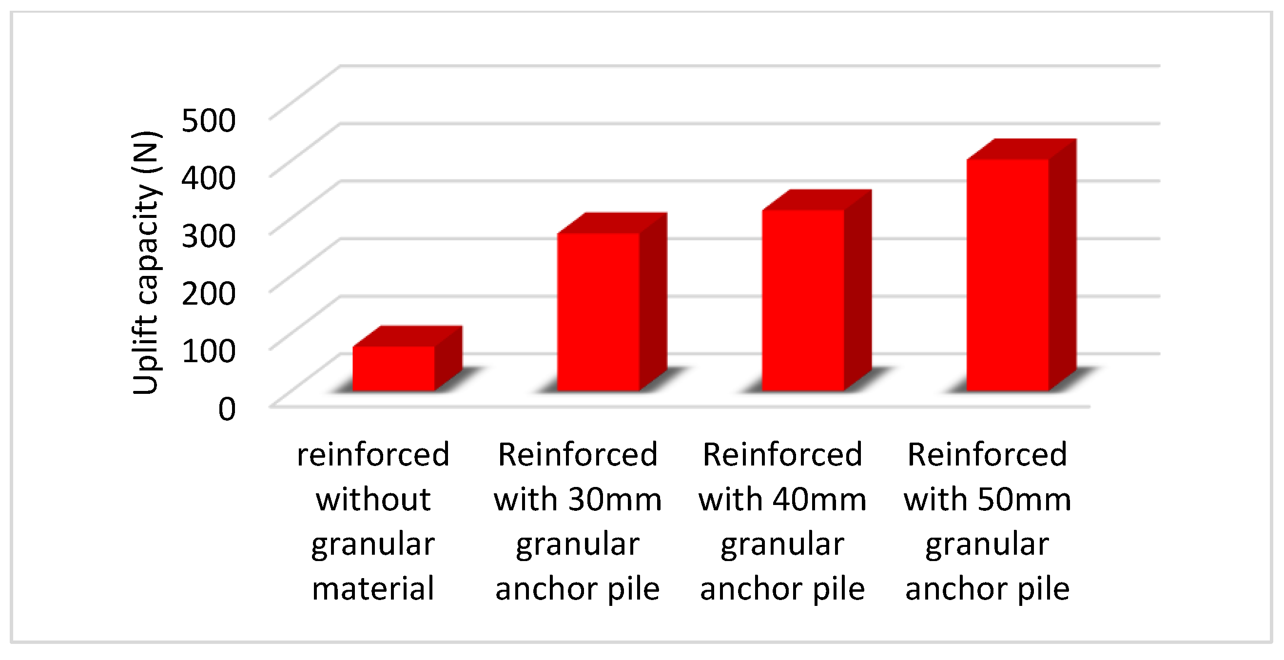
  • The granular anchor piles significantly reduced both the magnitude and rate of heave. Compared to an unreinforced expansive clay bed, the full-depth granular anchor pile reduced heave by 70%, 87%, and 92% for 100, 150, and 200 mm diameters, respectively. Relative movement along the pile-soil interface mobilized uplift resistance, reducing heave. A larger interface surface area (diameter) created stronger uplift resistance and less heave, as shown in Figure 7. The results of laboratory-scale model granular anchor piles installed in expansive clay beds corroborate this performance [91]. Granular piles also act as drain paths due to their high hydraulic conductivity, reducing the time for moisture stabilization and heaving equilibrium [92,93].
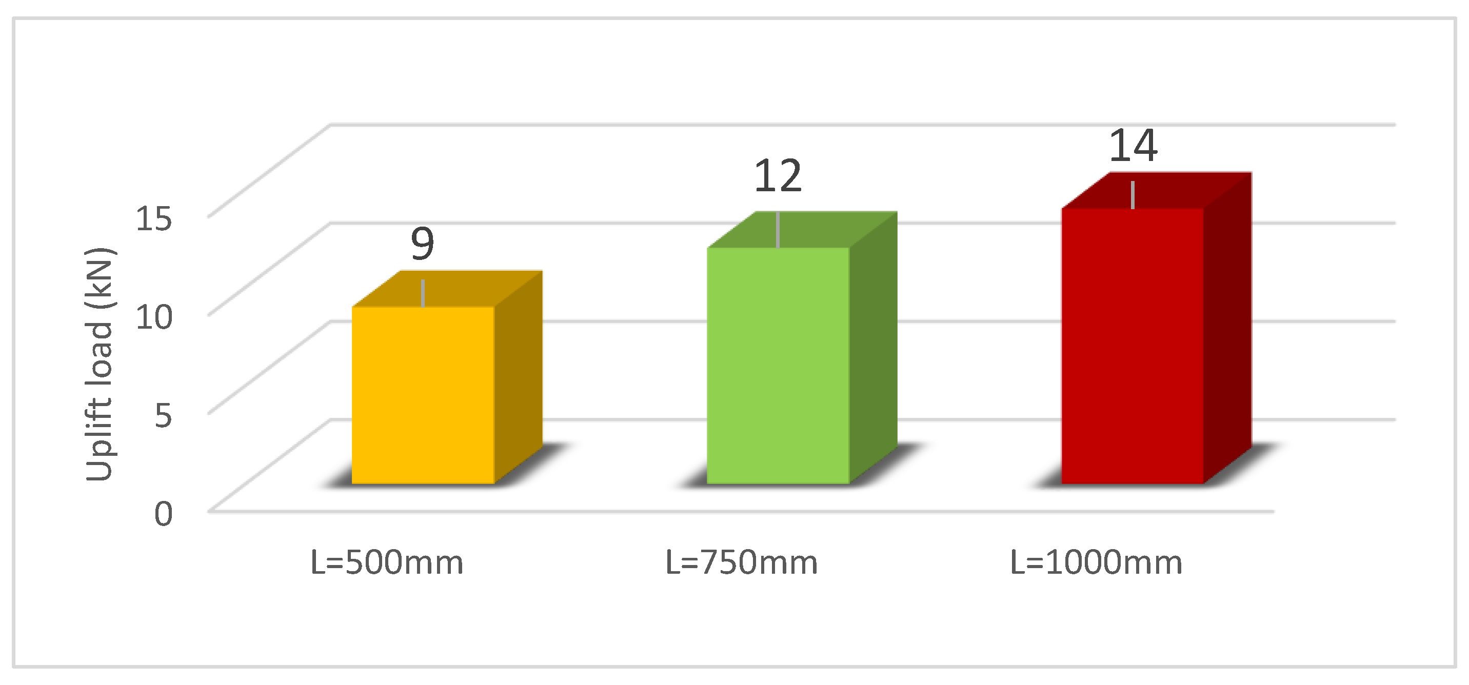
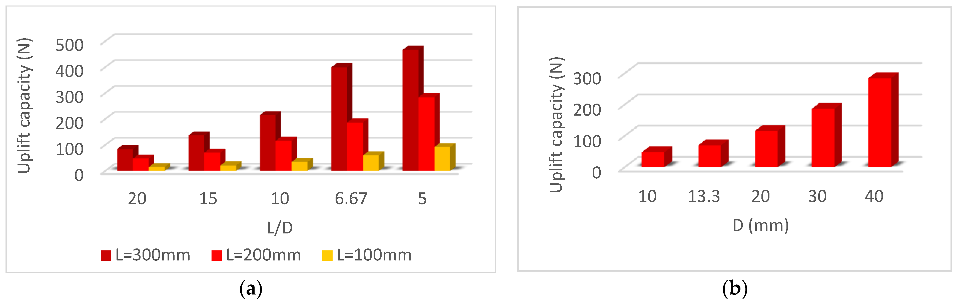
  • Increasing the length of the granular anchor piles increases the resistance to upward movement, which is consistent with Vashishtha and Sawant [94]. For granular anchor piles with lengths of 500, 750, and 1000 mm, the uplift load required to generate a 25-mm heave increased from 9 to 12, then 14 kN. The uplift load of the three different granular anchor piles with a diameter of 200 mm is shown in Figure 8.
  • The uplift resistance or failure pullout load increased as the diameter of the granular anchor piles increased, which is consistent with Vashishtha and Sawant [94]. The increase results from a larger area for skin friction resistance along the pile-soil interface. For example, a 25-mm upward movement generated resistances of 11, 11.5, and 14.2 kN for piles with 100, 150, and 200 mm diameters, respectively. Figure 9 shows the uplift load of the three piles, each with a length of 1000 mm.
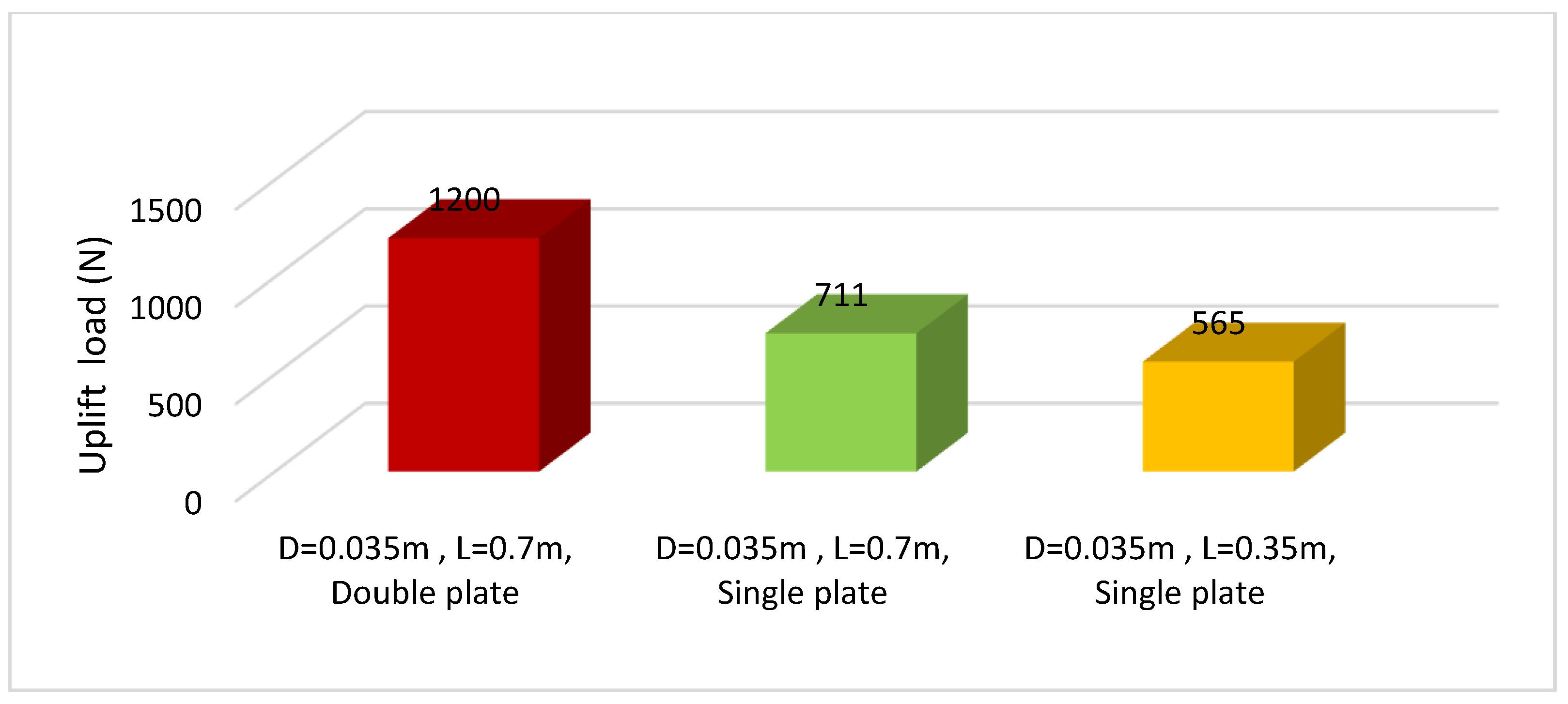
  • The pile group configuration consisted of five "passive" piles surrounding a sixth test pile. The test only loaded the center pile, while the surrounding piles contributed to the clay bed’s general stiffness and moisture equilibrium. Compared to the single pile, the center pile produced a higher uplift resistance for a given upward movement. The center pile resisted a pullout load of 18 kN, compared to 12 kN for individual piles, showing a 50% improvement. Figure 10 shows the uplift load of both tests.
To evaluate the compressive load response, Srirama Rao et al. [95] conducted field-scale plate load tests on granular anchor piles constructed in expansive clay beds. The dimensions of the granular anchor piles were the same as in the studies by Rao et al. [89] and Phanikumar et al. [90]. The test configurations varied: (1) unreinforced expansive clay beds; (2) expansive clay beds reinforced with a single granular anchor pile; and (3) expansive clay beds reinforced with a three-pile group. The plate could load both the clay bed and the piles at the same time or only the piles. The diameter and length of the pile group studied were kept constant at 150 mm and 1000 mm, respectively. For the single anchor piles, the embedment ratio varied between 2.5 and 7.5, while the diameter varied from 100–200 mm. Before testing, the researchers flooded the testing bin to encourage saturation and heaving. The findings revealed that, for a 25-mm settlement, the single pile required three times the compressive stress compared to the unreinforced bed.
Ismail et al. [96] analyzed granular anchor pile foundations in expansive soil using PLAXIS 2D and PLAXIS 3D software. The study investigated single and multiple pile behavior using a range of pile diameters and lengths. Their results corroborated previous testing and highlighted the benefits of increased pile diameter. The analyses also demonstrate that placing a group of piles under a footing rather than a single pile can decrease the efficiency of the granular anchor pile foundation system. In addition, pile spacing within the 2d to 4d range did not affect pile group efficiency significantly.
Sivakumar et al. [97] investigated the ultimate pullout capacity, load-displacement response, and failure mode of granular anchor piles. These authors also pointed out how to integrate this anchor properly into ordinary civil engineering construction. The experiments mentioned in this study follow in three parts.
The first section compares the ultimate pullout capacity of granular anchors to that of traditional concrete anchors cast in situ. These tests were carried out at Queen’s University Belfast (QUB) on old filled deposits with an experimental program evaluating two variables: granular anchor pile lengths (L) of 0.5, 1.0, and 1.5 m and granular anchor pile diameters (D) of 0.07 and 0.15 m.
The second part of the investigation examined the performance of granular anchors on a lodgment fill deposit at Trinity College Dublin’s Santry Sports Grounds. They used two lengths (L) (0.45, 1.62 m) and diameters (D) (0.15, 0.20 m).
The third part of the study included laboratory model tests at QUB. Soft, firm, stone-free clay (undrained shear strength cu = 30 kPa) was packed into a wooden box with dimensions of 1.2 × 0.7 × 0.7 m. The following three column configurations were investigated: (1) D = 0.035 m and L = 0.7 m with a single plate at the bottom of the column; (2) D = 0.035 m and L = 0.7 m with a plate at mid-height and a second plate at the bottom of the column; (3) D = 0.035 m and L = 0.35 m with a single plate at the bottom of the column.
For the first section, the pullout capacities of the concrete and granular anchors of L × D = 0.5 m × 0.07 m were 5.2 and 5.5 kN, respectively, according to the results. Both anchors failed due to shaft resistance deployed along the column’s length. The soil surrounding the concrete anchor did not experience any considerable displacement (either heave or subsidence) until it reached a failure state. Around the granular anchor, the soil gradually heaved as the anchor load increased incrementally to failure. The concrete anchor (L × D = 0.5 m × 0.15 m) failed at 8.0 kN capacity due to a loss of shaft resistance and ductile behavior. The corresponding granular anchor failed at 6.7 kN, exhibiting abrupt behavior. The granular anchor with L × D = 1.0 m × 0.07 m exhibited ductile failure with localized end bulging, whereas the concrete anchor failed in shaft resistance due to rapid pullout. The concrete and granular columns mobilized pullout capacities of 16.3 and 16.1 kN, respectively.
The second part of the experimental results on short anchors with lengths of L × D = 0.5 m × 0.196 m and 0.45 m × 0.148 m failed due to shaft resistance, mobilizing a 12 kN pullout capacity. The pullout capacity increased as anchor length and/or diameter increased. Anchors achieved pullout capacities of 39, 42, and 44 kN with L = 0.96, 1.0, and 1.3 m and D = 0.219 m, respectively. The pullout capabilities for 0.168 m diameter anchors were 33, 40, and 42 kN for L = 0.8, 1.47, and 1.62 m, respectively.
The third section shows that increasing the length and presence of a multiple-plate anchor system increases the granular anchor pile’s pullout capability (Figure 11).
Sivakumar et al. [97] came to an important conclusion: when the ratio of L/D > 7, localized bulging causes the granular anchor piles to collapse. It is particularly effective in transferring applied weight to strata at depth. However, short granular anchor piles failed due to shaft resistance and had a pullout capability similar to traditional cast-in-situ concrete anchors. Granular anchors have the advantages of being quick to install, low in cost, and able to withstand applied loads immediately after installation.
Krishna and Murty [98] tested the pullout capacities of granular anchor piles and conventional concrete piles in the lab and in the field and compared the results from both. Tests conducted in unsaturated and saturated conditions aided in the evaluation of capacity reduction. Results of the pile load tests appear in Figure 12, Figure 13 and Figure 14.
According to the results of the pullout tests conducted in the laboratory and the field under unsaturated and saturated conditions, granular anchor piles have a pullout resistance that is about three times that of identical concrete piles. According to the laboratory test results, the pullout resistance of granular anchor piles decreases by roughly 14% compared to the unsaturated state, while that of concrete anchor piles decreases by 26%. According to field experiments, granular anchor piles are reduced by roughly 25%, while concrete anchor piles are reduced by 32%.
Due to the complete packing and lateral displacement of granular fill caused by ramming, granular anchor piles have a high pullout resistance. The close interaction and interlocking of the sides of the borehole with such lateral displacement of granular fill are questionable in the case of concrete piles.
To study the behavior of the granular anchor pile in expansive soil, Aljorany et al. [87] used a laboratory test on an experimental model, as well as numerical modeling and analysis using PLAXIS 2D software. The effects of various parameters, such as granular anchor pile diameter, granular anchor pile length, footing diameter, non-expansive clay layer thickness (stable zone), and expansive clay layer thickness, were investigated. The results demonstrated the effectiveness of granular anchor piles in decreasing expansive soil heave. Based on the findings, three independent variables affect the heave of granular anchor piles: the L/D ratio, the L/H ratio, and the B/D ratio (where L is the length of a granular anchor pile, D is the diameter of a granular anchor pile, H is active soil thickness, and B is footing diameter/width). With a ratio of L/H = 1.0, the pile reduced heave by 38%. The reduction increased to 90% when the pile penetrated the stable zone to achieve L/H = 2.
Johnson and Sandeep [99] examined the effect of the relative density of the granular fill and pile diameter on pullout capacity. They compared encased and non-encased granular piles using a laboratory model test on black cotton soil (expansive soil). They performed pullout tests on a 30 mm-diameter anchor pile in a clay bed with a water content of 40%. The relative density of the granular fill varied from 50% to 70%. They also varied the pile diameter from 30 to 50 mm. A 30% increase in capacity resulted from the larger pile diameter.
Muthukumar and Shukla [100,101] conducted laboratory model tests to examine the heave reduction of soil due to granular anchor piles with and without encasement and helical anchor piles. The testing conditions consisted of: (1) a clay bed with no piles; (2) a granular pile without an encasement; (3) a granular pile with an encasement; and (4) a helical pile. All pile installations (2,3,4) reduced heave in the clay bed. The granular pile with encasement outperformed the one without, verifying the results of Roy et al. [66]. The encasement resists swelling forces and adds to the uplift resistance. Increasing the stiffness of the encasement produced higher confining stresses and greater resistance. Their granular piles performed better than helical piles, as shown in Figure 15.
Sharma [53] used PLAXIS 3D finite element software to conduct a numerical analysis to estimate the uplift performance of granular anchor piles in expansive soil. He applied an upward displacement of 10% of the pile diameter to the top. The expansive soil did not swell during the simulation, so volume change did not contribute to the model. He examined the effects of diameter (D), length (L), number of piles, pile spacing (s), and soil modulus (Es). The simulations revealed that the pile’s uplift capacity increases with increasing length and diameter (Figure 16a,b) and soil modulus (Figure 17). Single piles and pile groups showed similar behavior. Furthermore, the analysis showed that the ideal length-to-diameter ratio (L/D ratio) is between 10 and 13, beyond which uplift resistance increases only marginally.
Abbas [102] built a 30 cm-diameter and 55 cm-high testing tank to examine granular anchor piles in expansive clay. The clay mix consisted of 50% bentonite and 50% natural clay. Laboratory test results revealed the clay mix to have a liquid limit of 98, 15% free swell potential, and 210 kPa confined swell pressure. The expansive clay layer extended to a depth (H) of 25 cm, with a 20-cm-thick sand layer below it. Anchor piles reached the top of the sand or penetrated (Ls) 50–100 mm into it. The surface foundation measured 25 cm in diameter, while the piles varied between 20 and 50 mm. The effects of pile length (L), diameter (D), and depth of penetration into the sand layer influenced the heave resistance of the pile. The L/H, L/D, and Ls/H ratios provided dimensionless comparisons for performance.
Sharma and Sharma [103] studied the reaction of model granular anchor piles installed in poor clayey soil to pullout forces by altering pile length, diameter, and the relative density (RD) of granular fill material in a lab environment. They also studied the performance of crushed construction debris added to stabilize the clay. They modified the granular pile by reinforcing it with a geogrid. Four different combinations of clay and piles resulted. Their test results showed that longer piles and broader diameters increased pile capacity. Adding reinforcement with geogrids also increased capacity.
Khan and Gaddam [104] discussed several scale model tests in their work to better understand the heave and pullout behavior of the granular anchor pile foundation system. They investigated the effect of the spacing by using two granular piles at different separations. Compared to a reinforced expansive soil bed without granular material, the swell potential was lowered to around 68.09% for the 50-mm-diameter granular anchor pile (Figure 18a). The swell potential shrank with closer pile spacing (Figure 18b). According to Rao et al. [89], the 2D pile spacing produced the best results. A 50-mm-diameter granular anchor pile improved its pullout capacity by almost 400% (Figure 19).

6.2. Helical Piles

Helical piles offer deep foundation support in a prefabricated package. Unlike micro and driven piles, they have spiral blades that screw into the soil and provide compressive and tensile capacity.
The lead component of the helical pile is rotated into the soil first. Multiple helical blades attach to the square shaft; their size, shape, and number might vary. The lead is followed by several extensions, depending on the required torque or depth. Several extensions bolted together will achieve the desired depth of penetration. The top of the pile connects to the foundation system [105]. Figure 20 shows the components of a helical pile.

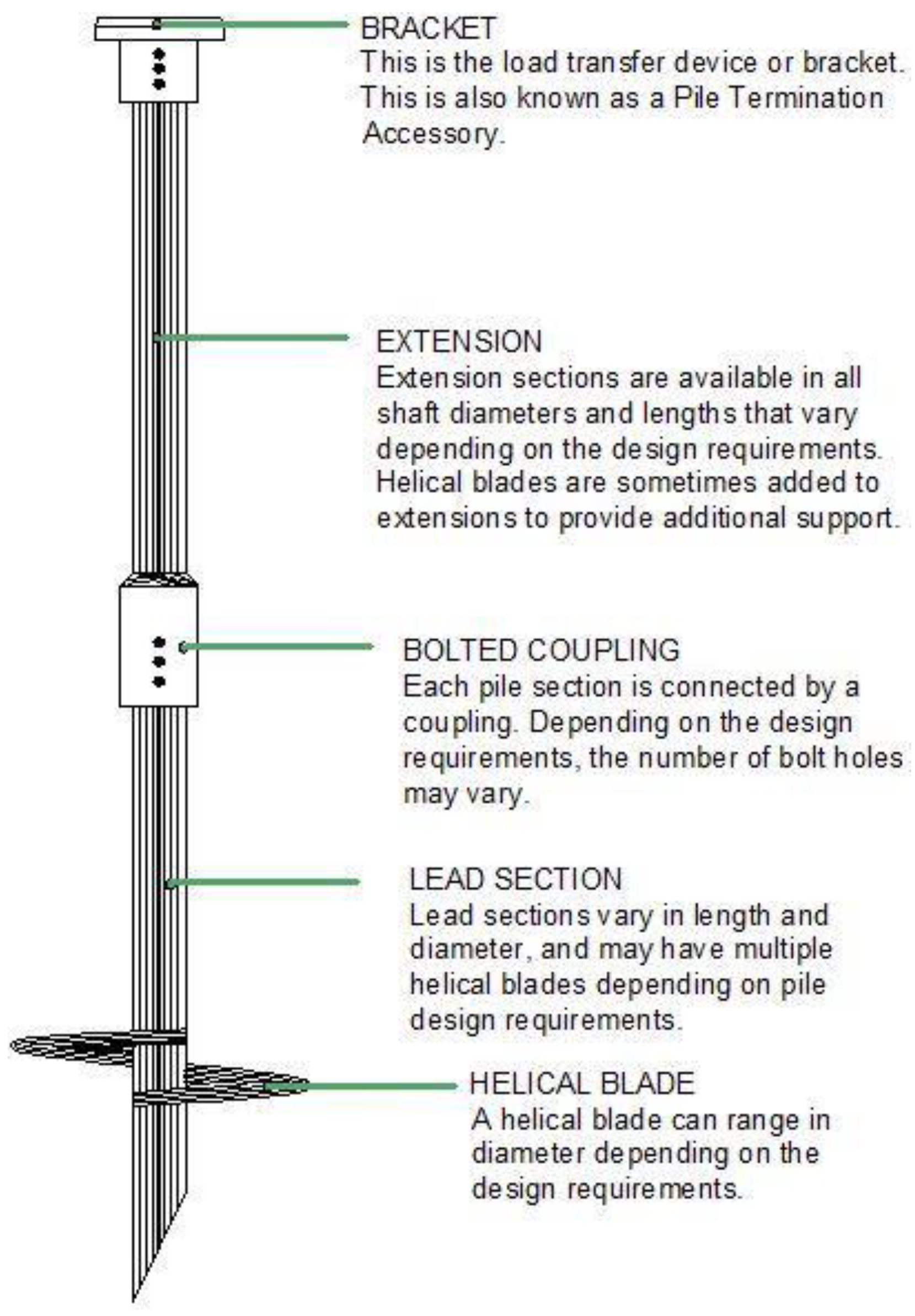
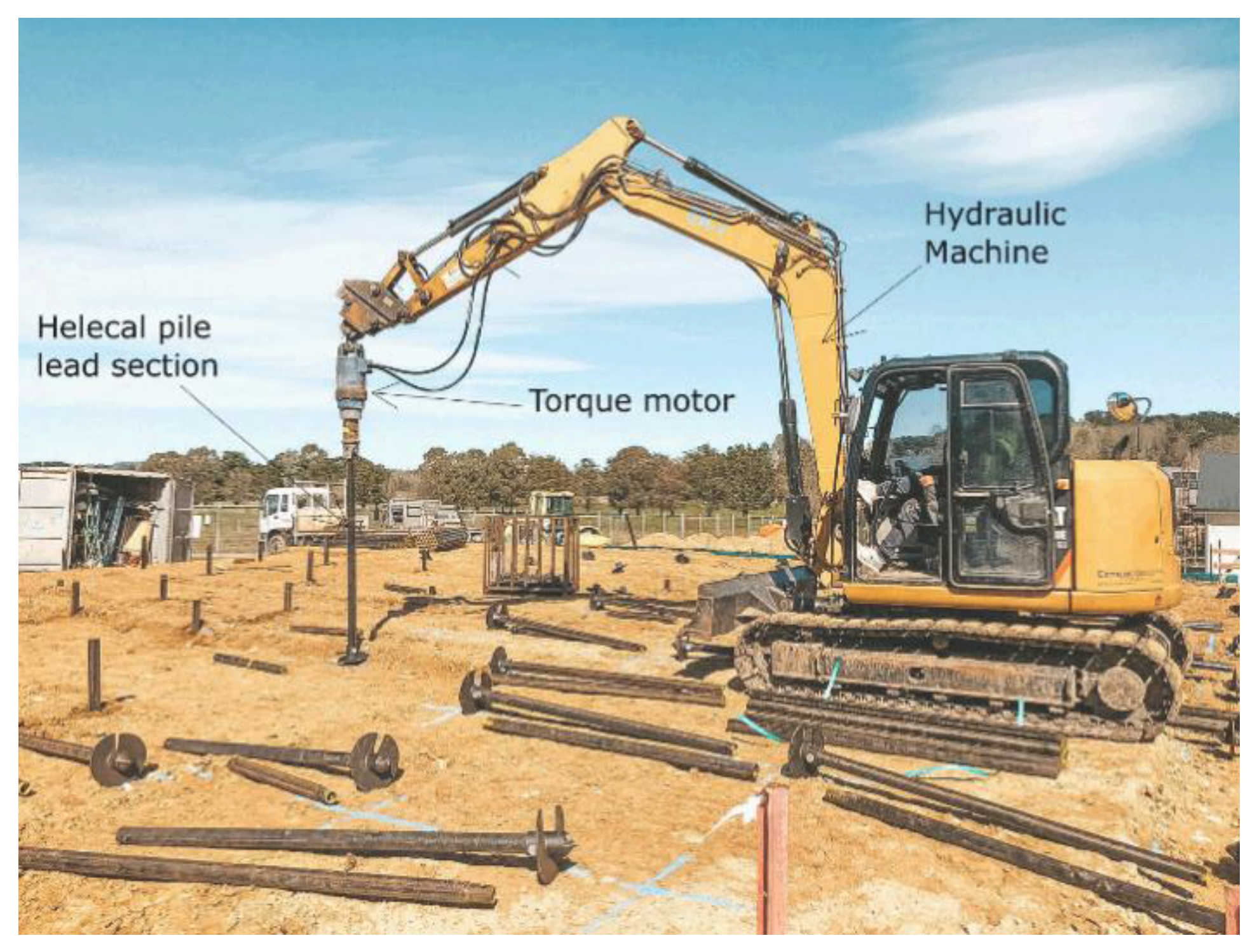
6.2.1. Helical Pile Installation

Helical piles install in a relatively straightforward manner. They require some special equipment, similar in size to a hydraulic excavator. While helical piles are easy to install, they require careful attention when subsurface conditions change or block installation. A truck-mounted auger or hydraulic torque motor attached to a backhoe, forklift, skid-steer loader, or other hydraulic equipment will turn the helical pile shaft into the soil [105]. Figure 21 shows typical installation equipment. The hydraulic motor is the system’s main component and applies torque (or rotating force) to the top of the helical pile. Motor speeds are usually slow to reduce disturbance by the blades during installation. Motors for helical pile installation typically deliver a torque of 6 to 100 kN-m or more [105]. The helix (helical bearing plate) installs below the depth of the active zone at a minimum of 5.4 kN-m of torque [106]. The torque motor should be able to rotate clockwise and counterclockwise and have an adjustable rotating speed. The equipment should have enough stability to maintain position and alignment during installation. Installation torque provides an estimate of pile capacity [105]. The relationship between capacity and torque has been thoroughly established empirically [107] and theoretically [108]. A torque indicator records torque levels during installation.
Pack [106] states that over 130,000 square shaft helical piers have provided remedial repair and foundations for new facilities in expansive soils since 1986, including the Front Range’s highly expansive bedrock. There have been no reported failures or poor performance of square shaft helical piers that were accurately specified and installed. The guiding principles for using square helical piers are as follows:
(1)
Install square-shaft helical piers with a minimum installation torque of 5.4 kN-m to ensure they penetrate below the active soil zone. The point at which the square shaft helical pier will not penetrate or advance deeper into the formation due to the density or hardness of the material is known as the "refusal depth."
(2)
Allow only a single helix lead section, so there is no significant bearing in the active zone.
(3)
Even when there is no dead weight, the small contact area of the square shaft reduces uplift forces on the pier to levels that eliminate heave.
(4)
Uplift forces on the pier remain negligible due to the smooth square shaft surface.
(5)
Water must not flow down the shaft’s sidewalls to the soil’s bearing depth. Migrating water may activate the lower soil.
(6)
Using IBC and ISO 9001-listed square shaft helical piers ensures that proper material is supplied and installed for expansive soil conditions.
(7)
Trained and experienced contractors can correctly install the square shaft helical piers in expansive soils.

6.2.2. Previous Research on Helical Piles

Mahmoudi and Ghanbari [35] acknowledge that there are few studies on the behavior of helical piles in expansive soils; therefore, more research is needed. In the following sections, a review of research will be conducted to determine the most critical aspects of the behavior of helical piles in expansive soils and highlight important considerations for future research.
Chao et al. [109] calculated the length required to achieve a 25 mm allowable movement for a variety of deep foundations (straight shaft pier, belled pier, helical pier) with a diameter of 25 cm installed in expansive soil for ideal and poor drainage conditions at various expansion potential (EP) values. The helical pier consisted of a single helix and a 3-inch-diameter steel shaft, with a minimum dead load of 50 kN on the piers. Figure 22 shows the required pier lengths for ideal and poor drainage conditions. The required pier length must increase about fivefold to overcome poor drainage, as illustrated in Figure 22. As a result, the required pier design lengths decrease dramatically with ideal surface drainage. However, such ideal surface drainage conditions rarely occur. Surface ponds form around structures, at least in localized areas, during times of irrigation. Helical piers, as opposed to belled piers, are effective under conditions of high expansion potential (EP) and poor drainage. This results from the helical piers’ negligible uplift from skin friction.
Al-Busoda and Abbas [110] mixed in soil additives during helical pile installation in expansive soil to examine their effects on upward movement and pullout force. The percentages of additives ranged from 0.5% to 6%. The helical piles extended 15 cm into the soil (L/D = 27) with a double helix (dh = 20 mm). Adding 3% silica fume, 3% coal fly ash, and 6% hydrated lime reduced the uplift movement of helical piles by more than 50%. Furthermore, a 3% mixture of (3:1) silica fume/coal fly ash or a 2% mixture of (1:1) hydrated lime and cement reduced uplift movement by more than 50%.
Al-Busoda and Abbas [111] examined helical pile models (dh = 15, 20 mm) drilled in an expansive soil bed over a sandy soil layer. They compacted a 200-mm-thick sand layer to 40% or 80% relative density. Above it, they compacted a 300-mm-thick layer of expansive soil. Helical piles (L = 350, 400, 450 mm; dh = 15, 20 mm) penetrated the sand layer with one or two helixes. Water then infiltrated around the helical pile from the bottom of the sandy soil to the surface of the expansive soil via four drains. They found that the upward movement of helical piles was reduced as the depth of the sandy layer, the helix diameter, and the number of helixes increased. In addition, increasing the relative density of the sand layer improved anchorage and reduced upward movement.
Al-Busoda and Abbas [112] conducted a study similar to [111] but focused on a single and a group of helical piles embedded in expansive soil. They used the same parameters as their previous study [111], except the pile lengths were 150, 200, and 300 mm, and they did not penetrate the sand. Four piles in a square pattern formed the group model. The length (L), diameter of helix (dh), and number of helices significantly impacted upward movement. The deeper helical piles with larger L/D ratios showed increased pullout capacity compared to the shallower piles, where D is the shaft diameter. The maximum upward movement of a group of helical piles was less than that of a single pile.
In the case of a single helical pile, increasing the L/D ratio for ordinary (no helix) and helical piles reduced the pile uplift movement caused by expansive soil, as illustrated in Figure 23a,b and Figure 24a,b. The long piles are anchored in a deeper soil layer, even though it is still within the active zone. When the L/D ratio increased from 27 to 53, upward movement decreased by 67% for plain piles, whereas single helix and double helix plates decreased by 84% and 77%. For short piles (L/D, L/H small), the ordinary pile demonstrated less uplift than the single or double helix piles, confirming Pack’s idea [106] that a helix within the active zone defeats the purpose of the helical design. The maximum uplift movement reduces with increasing penetration depth (larger L/H) due to the less expansive soil near the bottom of the layer and the action of the helical pile, as illustrated in Figure 25a,b.
In the case of a group of helical piles, similar to single helical piles, increasing the L/D ratio for a group of helical piles reduces the pile uplift movement caused by expansive soil. The long piles provide resistance by using the deeper soil layer. Even if it is within the soil’s active zone, it has much less moisture and does not expand. When increasing L/D from 27 to 53 for spacing (S = 3 DH), heave is reduced by 87–91% and 70–79% for single- and double-helix plates, respectively. For all L/D ratios, the helical pile group with a single helix demonstrated greater resistance than the group with a double helix. By lifting, the presence of helix plates in the active zone works against the pile’s purpose. Upward movement increases when the pile spacing increases, as shown in Figure 26. The benefits of confinement stress reduce as pile spacing increases, generating lower pullout capacity.
Al-Busoda et al. [41] investigated inclined and vertical helical piles under the base of retaining walls. The helical pile was made up of three 0.30 m diameter plates. Two at the pile shaft’s base provided vertical support in sandy soil. They had a separation distance five times their diameter (5 x dh). The third helix plate formed a rigid link with the footing of the retaining wall. The cross-section of the pile shaft measured 0.10 × 0.10 m, with two effective lengths (10 and 16 m). The authors found the best solution by placing two vertical helical piles and one inclined helical pile with an inclination of 30° from vertical. They chose a pile length to soil depth ratio of L/H = 3.2. In this case, the vertical movement was reduced by 94% and the lateral movement by 70%. In general, helical piles beneath retaining walls resist and control vertical movement but require inclined piles to resist lateral movement.
Albusoda and Abbase [42] modeled helical piles with PLAXIS 3D-2013 software. They applied the hardening soil model with volumetric strain expansion to mimic heave. A 44 m-high communication tower rested on an expansive soil layer 5 m deep. Wind loads and swelling soil generated uplift and lateral forces that required a pile foundation. The helical piles extended into dense, sandy soil beneath the expansive soil. Their effective lengths (7.50, 9.50, and 11.50 m) provided increasing resistance to uplift and lateral forces. Various patterns of piles created better or worse solutions to reduce the vertical and lateral movement of the tower. This study indicated that helical piles with double helix plates require L/D ratios of 118, 113, and 102 for helical pile groups of 2 × 2, 3 × 3, and 4 × 4 to achieve zero-uplift movement of the tower foundations. The L/H ratio could be achieved (1.52, 1.37, and 1.20) for helical pile groups of 2 × 2, 3 × 3, and 4 × 4, with double helix plates for zero-uplift. The pile groups also provided good resistance to lateral movement in general.
Mulyanda et al. [113] tested uplift loading on helical piles with diameters of 15, 20, and 25 cm. They also placed plates with different diameters on the same shaft. Their principal findings were:
  • As the diameter of the helix increases, so does the uplift capacity in a nearly-linear relationship.
  • Tapered plate configurations have capacities similar to their average diameter if the largest plate is on top.
Their study consisted of only five tests, so any further generalizations would not be appropriate.

7. Comparison between Helical and Granular Anchor Piles

The review study finds that helical and granular anchor piles are current alternative methods that mitigate the adverse effects of expansive soils. Most research has shown that they effectively reduce heave and increase bearing capacity.
Granular anchor piles are simple to install and do not require specialized expertise or equipment. However, they take longer to install because they require excavation and then backfilling with gravel soil, as opposed to the faster helical piles, which install directly both vertically and at an incline but require special equipment for installation and torque measurement.
The measured torque helps to predict the bearing capacity. It is a critical indicator of reaching the stable soil zone below the active zone when torque exceeds about 5.4 kN-m (Pack [106]). The indicator ensures consistent performance of the helical piles, which is less predictable for granular anchor piles.
Although few studies compare the performance of granular anchor piles with that of helical piles, Muthukumar and Shukla’s study [100] found that granular anchor piles outperform helical piles. Since granular soil replaces some expansive soil, it provides more substantial resistance to uplift forces. Adding lateral confinement due to swelling contributes to greater strength by increasing friction at the pile-soil interface. Muthukumar and Shukla [100] did not consider the effects of soil disturbance resulting from their installation of helical piles. The disturbance would reduce swelling pressures in the active soil zone and anchor resistance at depth. These two actions would tend to cancel each other out.
Using laboratory model tests, Joseph et al. [37] compared the uplift capacity of granular anchor piles to helical piles. According to the findings, the granular anchor pile outperformed the helical pile. However, their study was conducted on medium-density sand rather than expansive soil.

7.1. Numerical Analysis Comparison Using PLAXIS 3D

This study used the program PLAXIS 3D to evaluate the effectiveness of both types of foundations in reducing heave caused by expansive soil. The analyses determined the pullout/pulldown loads of the helical and granular anchor piles. The numerical performance of piles using PLAXIS agrees with the results of laboratory and field tests [24,114]. Problem complexity and the challenges of laboratory and field tests make numerical analysis an appealing method for the comparative parametric study of the targeted piles in this work [115].

7.1.1. Problem Description

The investigated problem consists of a shallow square footing (1.0 × 1.0 × 0.5 m) resting on an expansive soil layer and reinforced with a single granular anchor or helical pile. Varying lengths and a diameter of 0.6 m serve as input to the analysis (Table 7). The active zone of the expansive soil layer extends from the surface to a 4-m depth, where stable, saturated, dense sand lies beneath with a thickness of 10 m.

7.1.2. Methodology

Figure 27 shows a cross-sectional view of unreinforced and reinforced soil with helical and granular anchor piles. The 3D model calculated heave for three lengths of granular anchor piles and helical piles where saturation occurred from the top (water infiltration) or from the bottom (rising ground water). Pullout load and structural load capacities allowed for realistic design comparisons.

Input Data

Model geometry appears in Figure 27 and Table 7. The model domain measured 10 m long, 10 m wide, and 14 m deep. The borehole option created the first layer of expansive soil with a thickness of 4 m and the second layer of sand 10 m thick. The volume for helical and granular anchor piles occupied the middle of the model. Soil properties simulated the construction process, where fill sand replaced expansive soils as the granular pile developed. Both piles contained beam and plate elements as well.
The hardening soil model represented the expansive clay and sand layers and the sand fill used in the granular pile. Anchor plates and the surface footing contained steel and concrete. Both behaved elastically. Table 8 and Table 9 list all materials and constitutive models as cited by the Swiss Standard [116]; Xiao et al. [117]; Adem and Vanapalli [118]; and Pack [119]. Table 10 contains the properties of sand and expansive soil following disturbance from the helical pile installation [120].

Boundary Conditions

Horizontal displacements are assumed to be zero at the lateral boundaries. In addition, both horizontal and vertical displacements equal zero at the bottom. This assumption corresponds to natural behavior in which surrounding soil at large horizontal distances functions as horizontal fixities [121]. After assigning all necessary inputs to the model, Plaxis generated the mesh shown in Figure 28. A coarse mesh is used for both types of piles, with some refinement around the piles (the number of soil elements is 14,526 and the number of nodes is 22,207).

Initial Condition and Calculation Phases

The water table was assumed to be at the base of expansive soil when the initial conditions were assigned. Then, using Jacky’s formula, initial stresses were calculated by assuming coefficients of earth pressure at rest, K0 = 0.536 and K0 = 0.4 for expansive soil and sand, respectively, where K0 = 1-sin.
In this numerical analysis, there were seven stages of construction. The soil behavior during all phases is plastic because the duration of construction (i.e., consolidation) does not impact behavior in this problem.
  • In the first step, soil volume deactivation created the borehole for helical or granular anchor pile installation. Anchor plate, anchor rod, and granular anchor material, or disturbed sand and clay, are activated.
  • The second analysis step activated the footing plate.
  • The third analysis step applied the load to the footing (40 kN/m2).
  • During the fourth step, a volumetric strain of 8% was applied to each part of the ex-pansive soil volume from top to bottom to simulate heave.
  • The next step continued in one of three possible directions:
  • (A) The same volumetric strain of 8% was applied from the bottom upward.
  • (B) An upwardly prescribed displacement of 25 mm on the surface footing generated the tensile resistance of the pile.
  • (C) A downward displacement of 25 mm on the surface footing produced compres-sive resistance in a pile.
The change in volumetric strain mimics the heave of the clay in the analysis (positive volumetric strain). It is related to the degree of saturation in the expansive soil. Complete swelling occurs at a water content of 30%, following an S-shaped curve as determined by Tripathy et al. [122]. For highly plastic clays with porosities ranging from 0.4 to 0.6, the degree of saturation equivalent to 30% moisture content would be around 90% [123]. As a result, the moisture-swell function can provide 100% swelling at a saturation level of approximately 90% (Figure 29). Al-Shamrani and Dhowian [124] demonstrated that data from the triaxial compression test predicted field measurements of surface heave and reported that the results of the traditional oedometer test are about 1/3 as accurate as the actual surface heave. As a result, the maximum volumetric strain is 8%, which is 1/3 of the maximum free swell value obtained by Thakur and Singh [125]. This study uses an 8% positive volumetric strain for comparison.

7.2. Comparison between Helical and Granular Anchor Piles: Results of Numerical Analysis

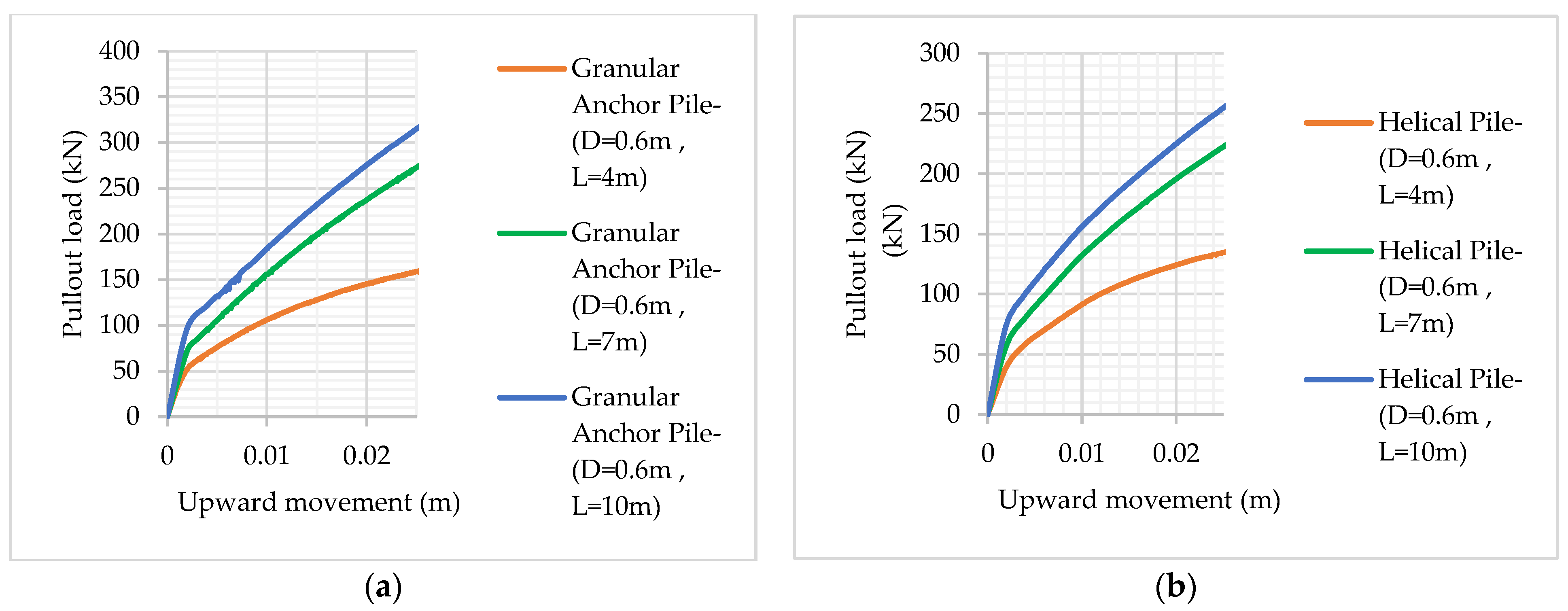
7.2.1. Pullout Load Comparison

Increasing the granular anchor pile and helical pile length increases the pullout load required to resist an upward movement (25 mm). Table 11 shows the pullout loads for granular anchors and helical piles. Note from Table 11 that the granular anchor pile achieves an 18% to 25% better performance than the helical pile. The granular anchor pile has a larger contact area with the soil, giving it better friction resistance. The helical pile disturbs and weakens the soil during its installation, reducing resistance. The pullout behavior of the three different lengths of granular anchors and helical piles with a diameter of 0.6 m is shown in Figure 30.

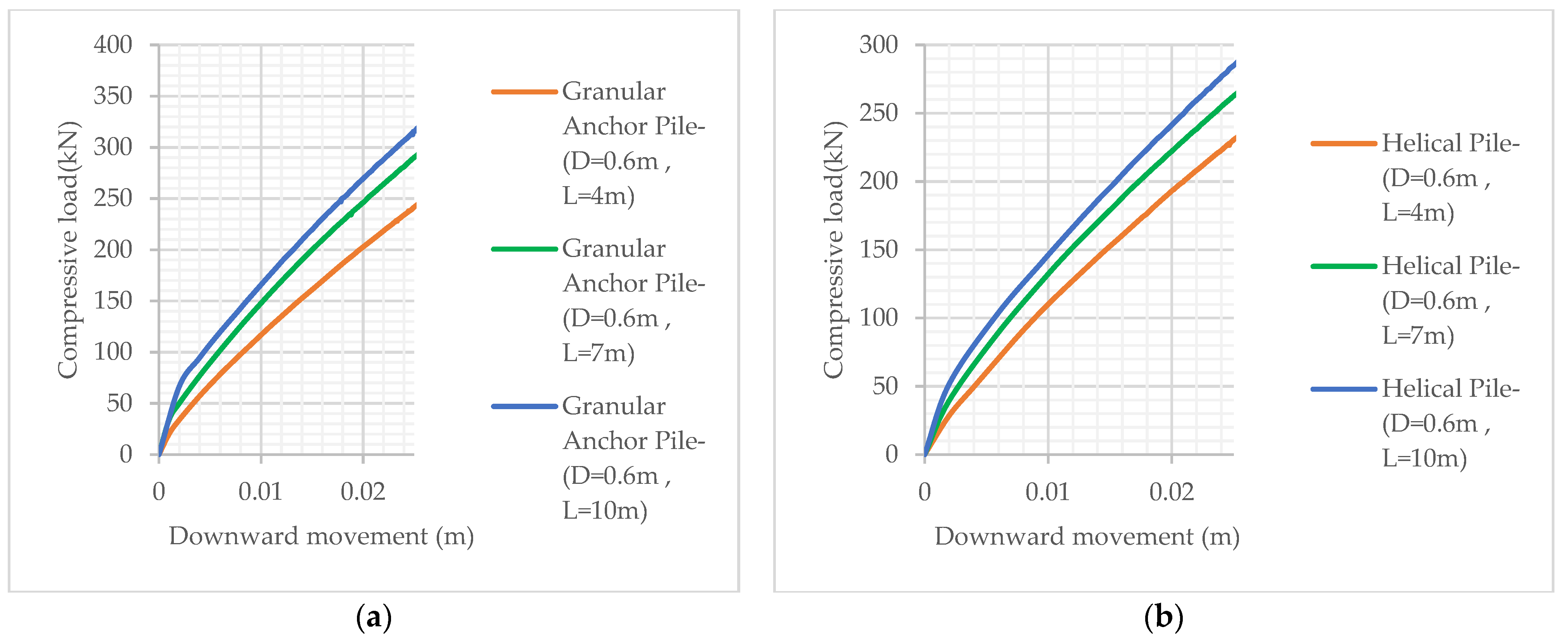
7.2.2. Compressive Load Comparison

Increasing the pile lengths increases the load resistance for a 25 mm displacement. Table 12 shows the loads for both granular anchors and helical piles. Note from Table 12 that the granular anchor pile achieves a 4% to 11% better performance than the helical pile. Figure 31 presents the compressive load behavior of the three lengths of granular anchors and helical piles with a diameter of 0.6 m.

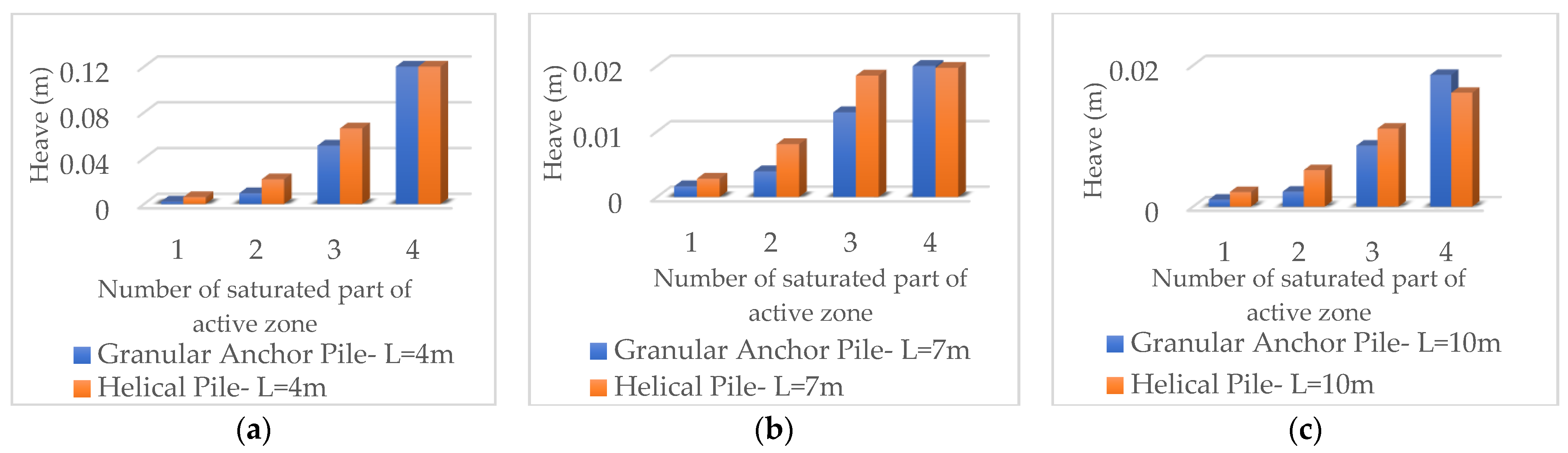
7.2.3. Heave Comparison

This section presents heave reductions from three lengths of granular anchor and helical piles. The analysis examines the effects of saturation going downward from the top (rainfall infiltration) versus upward from the bottom (groundwater rise). The heave comparison looks at movement as each successive meter of the active zone saturates until it is completely saturated. Figure 32 illustrates the possible directions of moisture migration.

Tarting Saturation from the Top (Case 1)

One can observe from Figure 33 that the soil expands as each successive meter of the active zone saturates. The piles behave similarly when both remain in the active zone (L = 4 m). If the piles penetrate the stable soil below (L = 7, 10 m), heave reduces drastically (by 1/5), with the two types of piles exhibiting slightly different behavior. At the final stage of saturation, both piles resist heaving nearly equally, with granular anchor piles slightly better. They perform better under more confining stresses. The stresses generate higher interface friction for the granular anchor piles and hold the helix more tightly for the helical piles. The behavior is consistent with Muthukumar and Shukla’s study [100]. However, there are some minor differences due to the smaller scale of their tests. Figure 34 further highlights the benefits of penetration into the stable zone.

Starting Saturation from the Bottom of Active Soil (Case 2)

Figure 35 demonstrates a fundamental difference between the two pile types. As the initial saturation occurs, the granular pile loses some resistance and the helical pile does not. However, in the following wetting stages, the granular pile does not change, whereas the helical one does. Either way, the final heave for the non-penetrating piles (4 m) is less than the top-down saturation (see Figure 35a vs. Figure 33a). Saturation from the bottom (Figure 35b,c) produces roughly half the heave as seepage from the top (Figure 33b,c) for penetrating piles. For Figure 35b,c, the granular pile yields with the first stage of moisture migration, followed by the helical pile in later stages.
Figure 35 shows a heave comparison for each stage. In this case, the effectiveness of the helical pile and granular anchor pile becomes close, and the effectiveness of the granular anchor pile becomes better at full saturation. Figure 36 further highlights the benefits of penetration into the stable zone. The percentage of heave reduction when increasing the length from 4 to 7 m and at full saturation of the active zone is 77% and 85% for the helical pile and granular anchor pile, respectively.
Table 13 compares the heave values of the two types of piles and the percentage of heave reduction for each type compared to the no-pile scenario. At full saturation, the reduction percentages are close for both types of piles; when L/H > 1.5, where H is the thickness of the active zone, and the reduction percentage exceeds 90%.
Table 14 shows the comparison between helical and granular anchor piles, straight piles, and under-reamed piles, considering the review and numerical study.

8. Advantages of Granular Anchor Piles and Helical Piles

Helical and granular anchor piles are foundations used at a construction site to support and stabilize structures. They are frequently employed when conventional foundation techniques are neither feasible nor practical [27]. Granular and helical anchor piles enjoy several social and environmental advantages. One advantage is that they can be installed quickly with less disruption. In urban areas, construction may disrupt local businesses and residents.
Also, helical and granular anchor piles are frequently more cost-efficient than other foundation types, making them more affordable for projects of all sizes [27,37]. Developers now have a simpler way of building new structures, which lowers economic risk and promotes development and economic growth. Finally, helical and granular anchor piles reduce material demand, making them more environmentally friendly than other foundations. Concrete is a significant contributor to greenhouse gas emissions during production, but it is absent from these foundations. Additionally, the smaller environmental impact of these foundations will mitigate the effects of construction on the surrounding environment. In general, helical and granular anchor piles can support the development of cost-effective, efficient, and sustainable infrastructure, which can benefit society.

9. Conclusions

The conclusions and recommendations based on the literature review and numerical study for the use of granular anchor piles and helical piles are as follows:
  • Granular anchors and helical piles offer practical solutions to expansive soil foundation problems by limiting heave and providing structural support.
  • According to field and laboratory studies, the granular anchor pile appears to be on par with or better than some currently employed tension-resistant foundation systems, such as concrete straight shaft piles, belled piles, and helical piles.
  • The two types of failure reported were shaft failure and localized swelling failure at the granular anchor pile’s base. Short granular anchor piles experienced shaft failure, while long granular anchor piles experienced localized bulging failure.
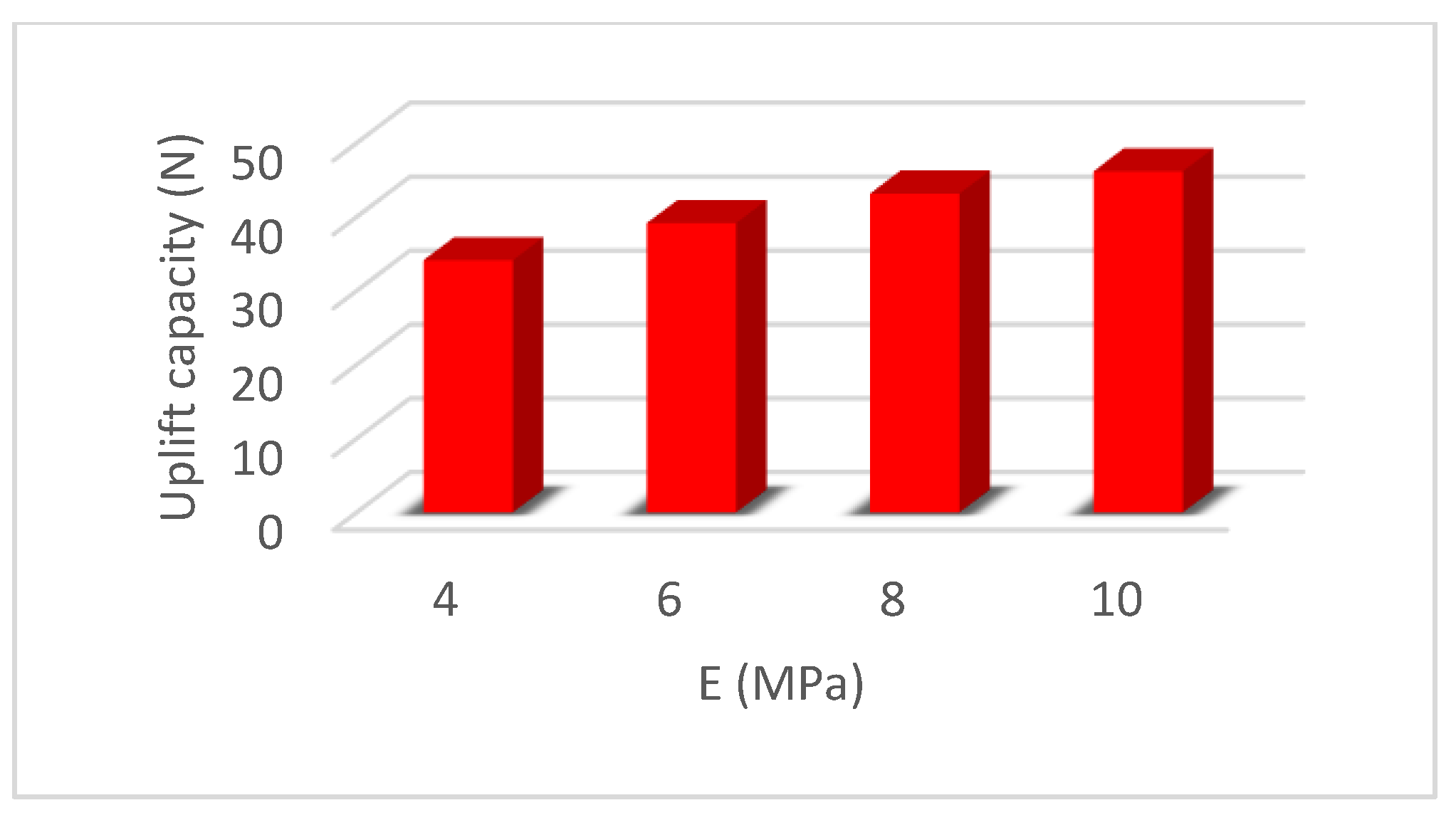
  • The ideal length-to-diameter ratio is between 10 and 13, after which there is no considerable increase in the uplift resistance. The diameter of the granular anchor pile influences the uplift resistance more than the length. Uplift resistance increases as the granular fill’s elastic modulus and relative density increase. The granular anchor pile’s uplift capacity decreases as the moisture content of the surrounding soil increases.
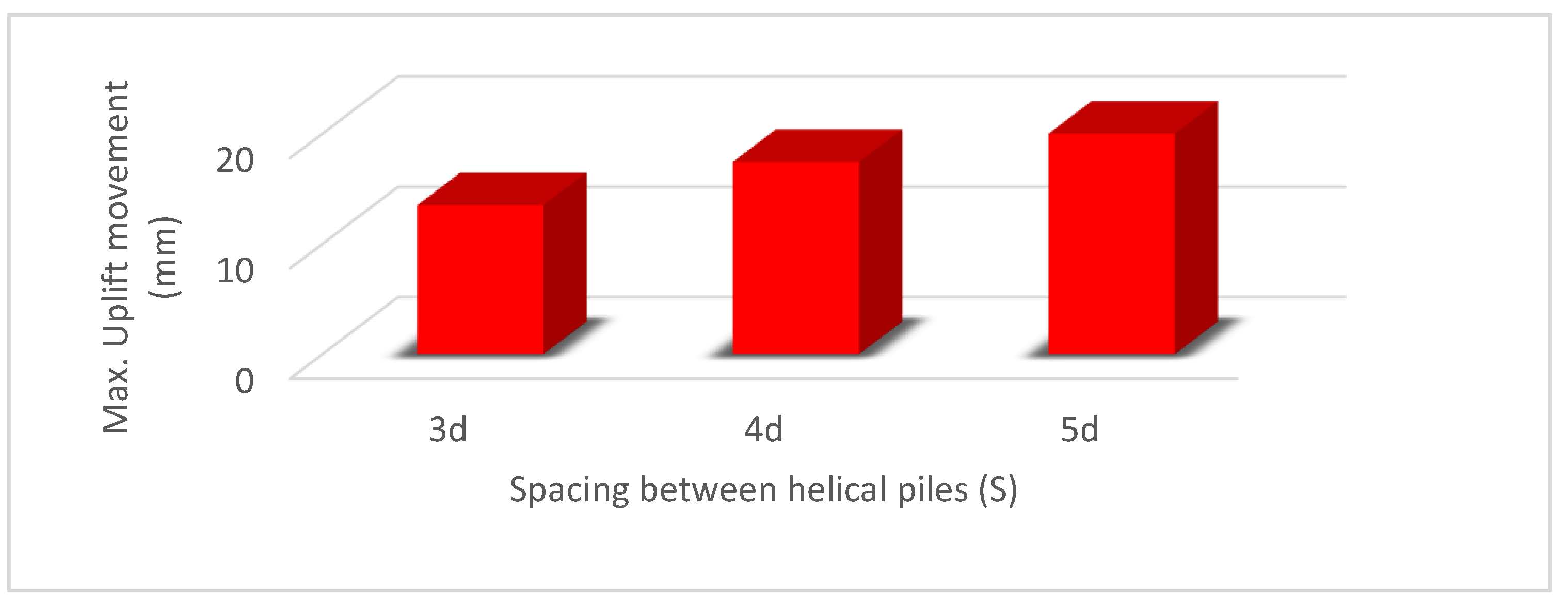
  • Granular anchor pile groups installed in expansive soil reduce heave better than single piles, but their ideal spacing and arrangement require additional research.
  • Soil modifiers added during helical pile installation in expansive soil (adding 3% silica fumes, 3% coal fly ash, 6% hydrated lime, 3% mixture of silica fumes to coal fly ash [3:1] or a 2% mixture of hydrated lime: cement [1:1]) reduces the uplift movement of helical piles by more than 50%.
  • Helical pile length, number of helixes, and their diameter significantly impact the amount and rate of upward movement. The deeper helical piles with larger L/D ratios showed pullout capacity greater than the shallower piles. The maximum upward movement of a group of helical piles is less than a single pile.
  • Installing square shaft helical piers with a minimum installation torque of 5.4 kN-m, or to refusal, ensures that the helix (helical bearing plate) embeds below the depth of seasonal moisture change (active zone).
  • A single helix will embed below the active zone, while a second helix above it may cause unwanted lift.
  • The granular anchor pile outperforms the helical pile in resisting pullout and compressive forces. The degree of performance improvement increases with pile length, reaching up to 24.5% for uplift force and 11% for downward force.
  • In numerical study case 1, as the active zone became more saturated, the granular anchor pile’s relative effectiveness decreased compared to the helical pile. When both piles increase from 4 to 7 m long and the active zone is fully saturated, the heave is reduced by approximately 84%.
  • In numerical study case 2, when the piles are entirely within the active zone, the helical pile resists heaving better than the granular anchor pile. Heaving decreases significantly as pile length penetrates beyond the active zone. During full saturation of the active zone, the piles with 7 and 10 m lengths reduced heave by 77% and 85% for the granular anchor and the helical pile, respectively.
  • Most numerical studies of the behavior of helical or granular anchor piles in expansive soils ignored the change in suction in expansive soils. Instead, they imposed a volume change inside the effective area, an approximation that does not represent field conditions. Future studies will need to account for changes in suction and effective stress and their effect on the volume change of the expansive soil. Our program will conduct future research on this topic.

Author Contributions

Conceptualization, A.A. and R.P.R.; investigation, A.A.; writing—original draft preparation, A.A. and R.A.; numerical modeling, A.A., R.P.R. and R.A.; writing—review and editing, R.P.R.; supervision, R.P.R. All authors have read and agreed to the published version of the manuscript.

Funding

This research received no external funding.

Informed Consent Statement

Not applicable.

Conflicts of Interest

The authors declare no conflict of interest.

References

  1. Stoll, S.C.; Henning, S.R.; Bagley, A.D.; Wieghaus, K.T. Foundation Damage Assessments and Structural Repairs. In Forensic Engineering; American Society of Civil Engineers: Denver, Colorado, 2022; pp. 166–174. ISBN 9780784484548. [Google Scholar]
  2. Baer, D.H. Building Losses from Natural Hazards: Yesterday, Today and Tomorrow; JH Wiggins Co.: London, UK, 1978. [Google Scholar]
  3. Karim, M.R.; Rahman, M.M.; Nguyen, H.B.K.; Kazmi, S.; Devkota, B.; Karim, R.; Rahman, M.; Bao, H.; Nguyen, K. Accounting for Expansive Soil Movement in Geotechnical Design&mdash;A State-of-the-Art Review. Sustainability 2022, 14, 15662. [Google Scholar] [CrossRef]
  4. Bowles, J.E. Foundation Analysis and Design; McGraw-Hills Inc.: New York, NY, USA, 1988; ISBN 0070067767. [Google Scholar]
  5. McOmber, R.M.; Thompson, R.W. Verification of Depth of Wetting for Potential Heave Calculations. In Advances in Unsaturated Geotechnics; 2000; pp. 409–422. Available online: https://ascelibrary.org/doi/10.1061/40510%28287%2928 (accessed on 15 March 2022).
  6. Nelson, J.D.; Overton, D.D.; Durkee, D.B. Depth of Wetting and the Active Zone. In Proceedings of the Expansive Clay Soils and Vegetative Influence on Shallow Foundations, London, UK, 8 October 2001; pp. 95–109. [Google Scholar]
  7. Walsh, K.D.; Colby, C.A.; Houston, W.N.; Houston, S.L. Method for Evaluation of Depth of Wetting in Residential Areas. J. Geotech. Geoenvironmental Eng. 2009, 135, 169–176. [Google Scholar] [CrossRef]
  8. Teodosio, B.; Kristombu Baduge, K.S.; Mendis, P. A Review and Comparison of Design Methods for Raft Substructures on Expansive Soils. J. Build. Eng. 2021, 41, 102737. [Google Scholar] [CrossRef]
  9. Ijaz, N.; Ye, W.; ur Rehman, Z.; Dai, F.; Ijaz, Z. Numerical Study on Stability of Lignosulphonate-Based Stabilized Surficial Layer of Unsaturated Expansive Soil Slope Considering Hydro-Mechanical Effect. Transp. Geotech. 2022, 32, 100697. [Google Scholar] [CrossRef]
  10. Fulzele, U.G.; Ghane, V.R.; Parkhe, D.D. Study of Structures in Black Cotton Soil. In Proceedings of the IRF International Conferece on Advances Sciences Engineering & Technology, Pune, India, 16 October 2016; Volume 4, ISBN 978-93-86291-14-1. [Google Scholar]
  11. Briggs, K.M.; Loveridge, F.A.; Glendinning, S. Failures in Transport Infrastructure Embankments. Eng. Geol. 2017, 219, 107–117. [Google Scholar] [CrossRef]
  12. Simons, K.B. Limitations of Residential Structures on Expansive Soils. J. Perform. Constr. Facil. 1991, 5, 258–270. [Google Scholar] [CrossRef]
  13. Zamin, B.; Nasir, H.; Mehmood, K.; Iqbal, Q. Field-Obtained Soil-Water Characteristic Curves of KPK Expansive Soil and Their Prediction Correlations. Adv. Civ. Eng. 2020, 2020, 1–13. [Google Scholar] [CrossRef]
  14. Dang, L.C.; Khabbaz, H.; Ni, B.J. Improving Engineering Characteristics of Expansive Soils Using Industry Waste as a Sustainable Application for Reuse of Bagasse Ash. Transp. Geotech. 2021, 31, 100637. [Google Scholar] [CrossRef]
  15. Medina-Martinez, C.J.; Sandoval-Herazo, L.C.; Zamora-Castro, S.A.; Vivar-Ocampo, R.; Reyes-Gonzalez, D. Natural Fibers: An Alternative for the Reinforcement of Expansive Soils. Sustainability 2022, 14, 9275. [Google Scholar] [CrossRef]
  16. Taleb, T.; Unsever, Y.S. Study on Strength and Swell Behavioral Change and Properties of the Clay&ndash;Fiber Mixtures. Sustainability 2022, 14, 6767. [Google Scholar] [CrossRef]
  17. Tiwari, N.; Satyam, N.; Puppala, A.J. Effect of Synthetic Geotextile on Stabilization of Expansive Subgrades: Experimental Study. J. Mater. Civ. Eng. 2021, 33, 04021273. [Google Scholar] [CrossRef]
  18. Tiwari, N.; Satyam, N. Coupling Effect of Pond Ash and Polypropylene Fiber on Strength and Durability of Expansive Soil Subgrades: An Integrated Experimental and Machine Learning Approach. J. Rock Mech. Geotech. Eng. 2021, 13, 1101–1112. [Google Scholar] [CrossRef]
  19. Tiwari, N.; Satyam, N.; Puppala, A.J. Strength and Durability Assessment of Expansive Soil Stabilized with Recycled Ash and Natural Fibers. Transp. Geotech. 2021, 29, 100556. [Google Scholar] [CrossRef]
  20. Li, H.; Wang, Y.; Yin, Z.; Al-Soudani, W.H.S.; Fattah, M.Y.; Ziyara, H.M.; Albusoda, B.S. An Experimental Study of the Load Carrying Capacity of Straight Shaft and Underreamed Piles in Expansive Soil. IOP Conf. Ser. Mater. Sci. Eng. 2021, 1067, 1–12. [Google Scholar] [CrossRef]
  21. Onur, M.İ.; Bıçakcı, M.; Kardoğan, P.S.Ö.; Erdağ, A.; Aghlmand, M. Laboratory model design for deep soil mixing method. Adv. Civ. Archit. Eng. 2022, 13, 59–69. [Google Scholar] [CrossRef]
  22. El-Samea, A.; Hassan, W.; Mowafy, Y.M.; El-Naiem, A.; Abdo, M.; Towfeek, A.R. numerical analysis of shallow foundation on expansive soil. J. Al-Azhar Univ. Eng. Sect. 2022, 17, 480–501. [Google Scholar] [CrossRef]
  23. Mansour, M.A.; El Naggar, M.H. Optimization of Grouting Method and Axial Performance of Pressure-Grouted Helical Piles. Can. Geotech. J. 2021, 59, 702–714. [Google Scholar] [CrossRef]
  24. Ziyara, H.M.; Albusoda, B.S. Experimental and Numerical Study of the Bulb’s Location Effect on the Behavior of under-Reamed Pile in Expansive Soil. J. Mech. Behav. Mater. 2022, 31, 90–97. [Google Scholar] [CrossRef]
  25. Roy, R.; Rao, C.N.; Mouli, S.S. Evaluation of Heave Behavior by Numerical Modeling of Granular Pile Anchor in Expansive Soil. Lect. Notes Civ. Eng. 2023, 297, 103–115. [Google Scholar] [CrossRef]
  26. Department of the Army USA Technical Manual TM 5–818–7, Foundations in Expansive Soils 1983. A: STPAGE2.PDF (army.mil).
  27. Das, B.M.; Shukla, S.K. Earth Anchors, 2nd ed.; J. Ross Publishing: Fort Lauderdale, FL, USA, 2013; ISBN 978-1-60427-077-8. [Google Scholar]
  28. Li, W. Centrifuge Modeling and Large Deformation Analyses of Axially Loaded Helical Piles in Cohesive Soils; University of Alberta: Edmonton, AB, Canada, 2022. [Google Scholar]
  29. Venkatesan, V.; Mayakrishnan, M. Behavior of Mono Helical Pile Foundation in Clays under Combined Uplift and Lateral Loading Conditions. Appl. Sci. 2022, 12, 6827. [Google Scholar] [CrossRef]
  30. Malhotra, H.; Sanjay; Singh, K. Effect of Load Inclination on the Uplift Capacity of the Granular Anchor Pile Foundation in Cohesive Soil. Arab. J. Geosci. 2022, 15, 1–11. [Google Scholar] [CrossRef]
  31. Yu, H.; Zhou, H.; Sheil, B.; Liu, H. Finite Element Modelling of Helical Pile Installation and Its Influence on Uplift Capacity in Strain Softening Clay. Can. Geotech. J. 2022. [Google Scholar] [CrossRef]
  32. Joseph, J.; Kumar, S.; Sawant, V.A.; Patel, J.B. An Experimental and Numerical Comparative Study on the Uplift Capacity of Single Granular Pile Anchor and Rough Pile in Sand. Int. J. Geotech. Eng. 2021, 16, 499–513. [Google Scholar] [CrossRef]
  33. Alwalan, M.; Alnuaim, A. Axial Loading Effect on the Behavior of Large Helical Pile Groups in Sandy Soil. Arab. J. Sci. Eng. 2022, 47, 5017–5031. [Google Scholar] [CrossRef]
  34. Mahmoudi-Mehrizi, M.E.; Ghanbari, A.; Sabermahani, M. The Study of Configuration Effect of Helical Anchor Group on Retaining Wall Displacement. Geomech. Geoengin. 2020, 17, 598–612. [Google Scholar] [CrossRef]
  35. Lin, Y.; Xiao, J.; Le, C.; Zhang, P.; Chen, Q.; Ding, H. Bearing Characteristics of Helical Pile Foundations for Offshore Wind Turbines in Sandy Soil. J. Mar. Sci. Eng. 2022, 10, 889. [Google Scholar] [CrossRef]
  36. Chaghameh, A.; Arjomand, M.; Adresi, M. Screw Pile and Its Application in Road’s Subgrade Improvement. Road 2022, 30, 197–206. [Google Scholar] [CrossRef]
  37. Joseph, J.; Kumar, S.; Patel, J.B.; Sawant, V.; Tandel, Y. Model Tests on Granular Pile Anchor and Helical Anchor: A Comparative Study. Int. J. Geosynth. Ground Eng. 2022, 8, 1–12. [Google Scholar] [CrossRef]
  38. Akhtar, N.; Ishak, M.I.S.; Ahmad, M.I.; Umar, K.; Md Yusuff, M.S.; Anees, M.T.; Qadir, A.; Almanasir, Y.K.A. Modification of the Water Quality Index (Wqi) Process for Simple Calculation Using the Multi-Criteria Decision-Making (Mcdm) Method: A Review. Water 2021, 13, 905. [Google Scholar] [CrossRef]
  39. Akhtar, N.; Syakir Ishak, M.I.; Bhawani, S.A.; Umar, K. Various Natural and Anthropogenic Factors Responsible for Water Quality Degradation: A Review. Water 2021, 13, 2660. [Google Scholar] [CrossRef]
  40. Sabatini, P.J.; Pass, D.G.; Bachus, R.C.; Consultants, G. Ground Anchors and Anchored Systems; United States Federal Highway Administration, Office of Bridge Technology: Washington, DC, USA, 1999.
  41. Al-Busoda, B.S.; Awn, S.H.A.; Abbase, H.O. Numerical Modeling of Retaining Wall Resting on Expansive Soil. Geotech. Eng. J. Seags Agssea 2017, 48, 116–121. Available online: https://www.researchgate.net/profile/Safa-Abid-Awn/publication/331522032_Numerical_Modeling_of_Retaining_Wall_Resting_on_Expansive_Soil/links/5c7e1bc392851c695054e094/Numerical-Modeling-of-Retaining-Wall-Resting-on-Expansive-Soil.pdf (accessed on 15 March 2022).
  42. Al-Busoda, B.S.; Abbas, H.O. Numerical Simulation of Mitigation of Soil Swelling Problem under Communication Tower Using Helical Piles. J. Geotech. Eng. 2017, 4, 35–46. Available online: https://www.researchgate.net/profile/Hassan-Abbas-17/publication/331135065_Numerical_Simulation_of_Mitigation_of_Soil_Swelling_Problem_under_Communication_Tower_Using_Helical_Piles/links/5c670f874585156b57ffeab3/Numerical-Simulation-of-Mitigation-of-Soil-Swelling-Problem-under-Communication-Tower-Using-Helical-Piles.pdf (accessed on 15 March 2022).
  43. Pérez, Z.A.; Schiavon, J.A.; de Tsuha, C.H.C.; Dias, D.; Thorel, L. Numerical and Experimental Study on Influence of Installation Effects on Behaviour of Helical Anchors in Very Dense Sand. Can. Geotech. J. 2017, 55, 1067–1080. [Google Scholar] [CrossRef]
  44. Elsherbiny, Z.H.; El Naggar, M.H. Axial Compressive Capacity of Helical Piles from Field Tests and Numerical Study. Can. Geotech. J. 2013, 50, 1191–1203. [Google Scholar] [CrossRef]
  45. George, B.E.; Banerjee, S.; Gandhi, S.R. Numerical Analysis of Helical Piles in Cohesionless Soil. Int. J. Geotech. Eng. 2017, 14, 361–375. [Google Scholar] [CrossRef]
  46. Nowkandeh, M.J.; Choobbasti, A.J. Numerical Study of Single Helical Piles and Helical Pile Groups under Compressive Loading in Cohesive and Cohesionless Soils. Bull. Eng. Geol. Environ. 2021, 80, 4001–4023. [Google Scholar] [CrossRef]
  47. Li, W.; Deng, L. Axial Load Tests and Numerical Modeling of Single-Helix Piles in Cohesive and Cohesionless Soils. Acta Geotech. 2019, 14, 461–475. [Google Scholar] [CrossRef]
  48. Vignesh, V.; Muthukumar, M. Experimental and Numerical Study of Group Effect on the Behavior of Helical Piles in Soft Clays under Uplift and Lateral Loading. Ocean Eng. 2023, 268, 1–18. [Google Scholar] [CrossRef]
  49. Garakani, A.A.; Serjoie, K.A. Ultimate Bearing Capacity of Helical Piles as Electric Transmission Tower Foundations in Unsaturated Soils: Analytical, Numerical, and Experimental Investigations. Int. J. Geomech. 2022, 22, 04022194. [Google Scholar] [CrossRef]
  50. Cheng, P.; Guo, J.; Yao, K.; Chen, X. Numerical Investigation on Pullout Capacity of Helical Piles under Combined Loading in Spatially Random Clay. Mar. Georesources Geotechnol. 2022, 1–14. [Google Scholar] [CrossRef]
  51. Kranthikumar, A.; Sawant, V.A.; Shukla, S.K. Numerical Modeling of Granular Anchor Pile System in Loose Sandy Soil Subjected to Uplift Loading. Int. J. Geosynth. Ground Eng. 2016, 2, 1–7. [Google Scholar] [CrossRef]
  52. Kranthikumar, A.; Sawant, V.A.; Kumar, P.; Shukla, S.K. Numerical and Experimental Investigations of Granular Anchor Piles in Loose Sandy Soil Subjected to Uplift Loading. Int. J. Geomech. 2017, 17, 04016059. [Google Scholar] [CrossRef]
  53. Sharma, R.K. A Numerical Study of Granular Pile Anchors Subjected to Uplift Forces in Expansive Soils Using PLAXIS 3D. Indian Geotech. J. 2019, 49, 304–313. [Google Scholar] [CrossRef]
  54. Malhotra, H.; Singh, S.K. Experimental and Numerical Studies on Pull-out Behavior of Granular Anchor Pile Foundation Embedded in Sandy Soil. Arab. J. Sci. Eng. 2021, 46, 4477–4487. [Google Scholar] [CrossRef]
  55. Mahmoudi-Mehrizi, M.-E.; Ghanbari, A. A Review of the Advancement of Helical Foundations from 1990–2020 and the Barriers to Their Expansion in Developing Countries. J. Eng. Geol. 2021, 14, 37–84. [Google Scholar] [CrossRef]
  56. Hosamo, H.H.; Nielsen, H.K.; Alnmr, A.N.; Svennevig, P.R.; Svidt, K. A Review of the Digital Twin Technology for Fault Detection in Buildings. Front. Built Environ. 2022, 8, 1–23. [Google Scholar] [CrossRef]
  57. Perianes-Rodriguez, A.; Waltman, L.; Van Eck, N.J. Constructing Bibliometric Networks: A Comparison between Full and Fractional Counting. J. Informetr. 2016, 10, 1178–1195. [Google Scholar] [CrossRef]
  58. Adem, H.H.; Vanapalli, S.K. Review of Methods for Predicting in Situ Volume Change Movement of Expansive Soil over Time. J. Rock Mech. Geotech. Eng. 2015, 7, 73–86. [Google Scholar] [CrossRef]
  59. Nelson, J.; Miller, D.J. Expansive Soils: Problems and Practice in Foundation and Pavement Engineering; John Wiley & Sons: New York, NY, USA, 1997; ISBN 0471181145. [Google Scholar]
  60. Holtz, R.D.; Kovacs, W.D.; Sheahan, T.C. An Introduction to Geotechnical Engineering; Prentice-Hall: Hoboken, NJ, USA, 1981; ISBN 0-13-484394-0. [Google Scholar]
  61. Holtz, W.G. Expansive Clays-Properties and Problems. Q. Colo. Sch. Mines 1959, 54, 90–125. [Google Scholar]
  62. Dakshanamurthy, V.; Raman, V. A Simple Method of Identifying an Expansive Soil. Soils Found. 1973, 13, 97–104. [Google Scholar] [CrossRef]
  63. AASHTO T258-81; Standard Method of Test for Determining Expansive Soils. American Association of State and Highway Transportation Officials: Washington, DC, USA, 2018.
  64. ASTM D4546-14; Standard Test Methods for One-Dimensional Swell or Collapse of Soils. ASTM International: West Conshohocken, PA, USA, 2014.
  65. Chen, F.H. Foundations on Expansive Soils; Elsevier: New York, NY, USA, 1975; Volume 12, ISBN 044460166X. [Google Scholar]
  66. Jones, L.D.; Jefferson, I. Expansive Soils. Volume 1, Geotechnical Engineering Principles, Problematic Soils and Site Investigation; ICE Publishing: London, UK, 2012; pp. 413–441. [Google Scholar]
  67. Peck, R.B.; Hanson, W.E.; Thornburn, T.H. Foundation Engineering, 2nd ed.; Wiley: New York, NY, USA, 1974; ISBN 978-0-471-67585-3. [Google Scholar]
  68. Murthy, V.N.S. Geotechnical Engineering: Principles and Practices of Soil Mechanics and Foundation Engineering; Marcel Dekker, Inc: New York, NY, USA; Basel, Switzerland, 2002; ISBN 0824708733. [Google Scholar]
  69. Zumrawi, M.M.E.; Abdelmarouf, A.O.; Gameil, A.E.A. Damages of Buildings on Expansive Soils: Diagnosis and Avoidance. Int. J. Multidiscip. Sci. Emerg. Res. 2017, 6, 108–115. [Google Scholar]
  70. Lytton, R.; Aubeny, C.; Bulut, R. Design Procedure for Pavements on Expansive Soils: Volume 3; Report 0–4; Texas Transportation Institute, Texas A & M University System: College Station, TX, USA, 2005. [Google Scholar]
  71. Rao, M.R.; Rao, A.S.; Babu, R.D. Arresting Heave of Expansive Soil Beds with Lime-Stabilised Flyash Cushion. J. Inst. Eng. Part CV Civ. Eng. Div. 2007, 87, 13–17. [Google Scholar]
  72. Murty, V.R.; Praveen, G.V. Use of Chemically Stabilized Soil as Cushion Material below Light Weight Structures Founded on Expansive Soils. J. Mater. Civ. Eng. 2008, 20, 392–400. [Google Scholar] [CrossRef]
  73. Walsh, K.D.; Houston, S.; Houston, W.N.; Harraz, A.M. Finite Element Evaluation of Deep-Seated Swell. In Proceedings of the 4th Asia Pacific Conference on Unsaturated Soils, Newcastle, Australia, 23–25 November 2010; pp. 731–736. [Google Scholar]
  74. Ahmed, A. Evaluation of Drying and Wetting Cycles with Soil Cushion to Mitigate the Potential of Expansive Soil in Upper Egypt. Electron. J. Geotech. Eng. 2009, 15, 1–11. [Google Scholar]
  75. Srinivas, K.; Prasad, D.S.V.; Rao, E. A Study on Improvement of Expansive Soil by Using Cns (Cohesive Non Swelling) Layer. Int. J. Innov. Res. Technol. 2016, 3, 54–60. Available online: http://ijirt.org/Article?manuscript=143878 (accessed on 15 March 2022).
  76. Gromko, G.J. Review of Expansive Soils. J. Geotech. Eng. Div. 1974, 100, 667–687. [Google Scholar] [CrossRef]
  77. O’Neill, M.W.; Poormoayed, N. Methodology for Foundations on Expansive Clays. J. Geotech. Eng. Div. 1980, 106, 1345–1367. [Google Scholar] [CrossRef]
  78. Prusinski, J.R.; Bhattacharja, S. Effectiveness of Portland Cement and Lime in Stabilizing Clay Soils. Transp. Res. Rec. 1999, 1652, 215–227. [Google Scholar] [CrossRef]
  79. Moayed, R.Z.; Haratian, M.; Izadi, E. Improvement of Volume Change Characteristics of Saline Clayey Soils. J. Appl. Sci. 2011, 11, 76–85. [Google Scholar] [CrossRef]
  80. Belabbaci, Z.; Mamoune, S.M.A.; Bekkouche, A. Stabilization of Expansive Soils with Milk of Lime: The Case of Clays of Tlemcen, Algeria. Electron. J. Geotech. Eng. 2012, 17, 1293–1304. [Google Scholar]
  81. Al-Taie, A.; Disfani, M.M.; Evans, R.; Arulrajah, A.; Horpibulsuk, S. Swell-Shrink Cycles of Lime Stabilized Expansive Subgrade. Procedia Eng. 2016, 143, 615–622. [Google Scholar] [CrossRef]
  82. Mahedi, M.; Cetin, B.; White, D.J. Cement, Lime, and Fly Ashes in Stabilizing Expansive Soils: Performance Evaluation and Comparison. J. Mater. Civ. Eng. 2020, 32, 1–16. [Google Scholar] [CrossRef]
  83. Jeyapalan, J.K.; Rice, G.T.; Lytton, R.L. State-of-the-Art Review of Expansive Soil Treatment Methods; Texas A & M University: College Station, TX, USA, 1981. [Google Scholar]
  84. Venkataramana, K. Building on Expansive Clays with Special Reference to Trinidad. West Indian J. Eng. 2003, 25, 43–53. Available online: https://sta.uwi.edu/eng/wije/vol2502_jan2003/documents/Buildingonexpansiveclays.pdf (accessed on 15 March 2022).
  85. Dafalla, M.A.; Shamrani, M.A. Road Damage Due to Expansive Soils: Survey of the Phenomenon and Measures for Improvement. In Proceedings of the GeoHunan International Conference, Hunan, China, 16 May 2011; pp. 73–80. [Google Scholar]
  86. Sorochan, E.A. Use of Piles in Expansive Soils. Soil Mech. Found. Eng. 1974, 11, 33–38. [Google Scholar] [CrossRef]
  87. Aljorany, A.N.; Ibrahim, S.F.; Al-Adly, A.I. Heave Behavior of Granular Pile Anchor-Foundation System (GPA-Foundation System) in Expansive Soil. J. Eng. 2014, 20, 1–22. Available online: https://www.iasj.net/iasj/download/f80b6b01950d0ef7 (accessed on 15 March 2022).
  88. Hugher, J.M.O.; Withers, N.J. Reinforcing of Soft Cohesive Soils with Stone Columns. Ground Eng. 1974, 7, 42–49. [Google Scholar]
  89. Rao, A.S.; Phanikumar, B.R.; Babu, R.D.; Suresh, K. Pullout Behavior of Granular Pile-Anchors in Expansive Clay Beds in Situ. J. Geotech. Geoenvironmental Eng. 2007, 133, 531–538. [Google Scholar] [CrossRef]
  90. Phanikumar, B.R.; Srirama Rao, A.; Suresh, K. Field Behaviour of Granular Pile-Anchors in Expansive Soils. Proc. Inst. Civ. Eng. Ground Improv. 2008, 161, 199–206. [Google Scholar] [CrossRef]
  91. Phanikumar, B.R.; Sharma, R.S.; Rao, A.S.; Madhav, M.R. Granular Pile Anchor Foundation (GPAF) System for Improving the Engineering Behavior of Expansive Clay Beds. Geotech. Test. J. 2004, 27, 279–287. [Google Scholar] [CrossRef]
  92. Cooper, M.R.; Rose, A.N. Stone Column Support for an Embankment on Deep Alluvial Soils. Proc. Inst. Civ. Eng. Geotech. Eng. 1999, 137, 15–25. [Google Scholar] [CrossRef]
  93. Muir Wood, D.; Hu, W.; Nash, D.F.T. Group Effects in Stone Column Foundations: Model Tests. Geotechnique 2000, 50, 689–698. [Google Scholar] [CrossRef]
  94. Vashishtha, H.R.; Sawant, V.A. An Experimental Investigation for Pullout Response of a Single Granular Pile Anchor in Clayey Soil. Int. J. Geo-Eng. 2021, 12, 1–19. [Google Scholar] [CrossRef]
  95. Srirama Rao, A.; Phanikumar, B.R.; Suresh, K. Response of Granular Pile-Anchors under Compression. Proc. Inst. Civ. Eng.-Ground Improv. 2008, 161, 121–129. [Google Scholar] [CrossRef]
  96. Ismail, M.; Shahin, M. Finite Element Analyses of Granular Pile Anchors as a Foundation Option for Reactive Soils. In Proceedings of the International Conference on Advances in Geotechnical Engineering, Perth, Australia, 7–9 November 2011; pp. 1047–1052. [Google Scholar]
  97. Sivakumar, V.; O’Kelly, B.C.; Madhav, M.R.; Moorhead, C.; Rankin, B. Granular Anchors under Vertical Loading–Axial Pull. Can. Geotech. J. 2013, 50, 123–132. [Google Scholar] [CrossRef]
  98. Krishna, P.H.; Murty, V.R. Pull-out Capacity of Granular Anchor Piles in Expansive Soils. IOSR J. Mech. Civ. Eng. 2013, 5, 24–31. [Google Scholar] [CrossRef]
  99. Johnson, N.; Sandeep, M.N. Ground Improvement Using Granular Pile Anchor Foundation. Procedia Technol. 2016, 24, 263–270. [Google Scholar] [CrossRef]
  100. Muthukumar, M.; Shukla, S.K. Comparative Study on the Behaviour of Granular Pile Anchors and Helical Pile Anchors in Expansive Soils Subjected to Swelling. Int. J. Geotech. Eng. 2017, 14, 49–54. [Google Scholar] [CrossRef]
  101. Muthukumar, M.; Shukla, S.K. Swelling Behaviour of Expansive Clay Beds Reinforced with Encased Granular Pile Anchors. Int. J. Geotech. Eng. 2016, 12, 109–117. [Google Scholar] [CrossRef]
  102. Abbas, H.O. Laboratory Study on Reinforced Expansive Soil with Granular Pile Anchors. Int. J. Eng. 2020, 33, 1167–1172. [Google Scholar] [CrossRef]
  103. Sharma, A.; Sharma, R.K. An Experimental Study on Uplift Behaviour of Granular Anchor Pile in Stabilized Expansive Soil. Int. J. Geotech. Eng. 2021, 15, 950–963. [Google Scholar] [CrossRef]
  104. Khan, H.A.; Gaddam, K. An Experimental Study on Heave and Uplift Behaviour of Granular Pile Anchor Foundation System. In Proceedings of the IOP Conference Series: Earth and Environmental Science, Surakarta, Indonesia, 24–25 August 2021; Volume 822, pp. 1–9. [Google Scholar]
  105. Perko, H.A. Helical Piles: A Practical Guide to Design and Installation; John Wiley & Sons: New York, NY, USA, 2009; ISBN 0470404795. [Google Scholar]
  106. Pack, J.S. Performance of Square Shaft Helical Pier Foundations in Swelling Soils. Geotech. Pract. Publ. 2007, 76–85. [Google Scholar] [CrossRef]
  107. Hoyt, R.M.; Clemence, S. Uplift Capacity of Helical Anchors in Soil. In Proceedings of the 12th International Conference on Soil Mechanics and Foundation Engineering, Rio de Janeiro, Brazil, 13–18 August 1989; pp. 1019–1022. [Google Scholar]
  108. Ghaly, A.; Hanna, A. Experimental and Theoretical Studies on Installation Torque of Screw Anchors. Can. Geotech. J. 1991, 28, 353–364. [Google Scholar] [CrossRef]
  109. Chao, K.C.; Nelson, J.D.; Overton, D.D. Factors Influencing Design of Deep Foundations on Expansive Soils. In Proceedings of the 5th Asia Pacific Conference on Unsaturated Soils, Pattaya, Thailand, 14–16 November 2011; Volume 2, pp. 829–834. [Google Scholar]
  110. Al-Busoda, B.S.; Abbase, H.O. Mitigation of Expansive Soil Problems by Using Helical Piles with Additives. J. Geotech. Eng. 2015, 2, 30–40. [Google Scholar]
  111. Al-Busoda, B.S.; Abbase, H.O. Helical Piles Embedded in Expansive Soil Overlaying Sandy Soil. Al-Khwarizmi Eng. J. 2016, 12, 19–25. [Google Scholar]
  112. Albusoda, B.S.; Abbase, H.O. Performance Assessment of Single and Group of Helical Piles Embedded in Expansive Soil. Int. J. Geo-Eng. 2017, 8, 1–20. [Google Scholar] [CrossRef]
  113. Mulyanda, D.; Iqbal, M.M.; Dewi, R. The Effect of Helical Size On Uplift Pile Capacity. Int. J. Sci. Technol. Res. 2020, 9, 4140–4145. Available online: https://repository.unsri.ac.id/49463/1/The-Effect-Of-Helical-Size-On-Uplift-Pile-Capacity.pdf (accessed on 15 March 2022).
  114. Sangeetha, S.; Hari Krishna, P. Analysis of Heave Behaviour of Expansive Soil Provided with Granular Pile Anchors Using Plaxis. Lect. Notes Civ. Eng. 2020, 55, 391–404. [Google Scholar] [CrossRef]
  115. Alsirawan, R.; Alnmr, A. Dynamic Behavior of Gravity Segmental Retaining Walls. Pollack Period. 2022, 1. [Google Scholar] [CrossRef]
  116. Dysli, M. Swiss Standard SN 670 010b, Characteristic Coefficients of Soils; Strasse und Verkehr: Zurich, Switzerland, 2000. [Google Scholar]
  117. Xiao, J.; Yang, H.; Zhang, J.; Tang, X. Properties of Drained Shear Strength of Expansive Soil Considering Low Stresses and Its Influencing Factors. Int. J. Civ. Eng. 2018, 16, 1389–1398. [Google Scholar] [CrossRef]
  118. Adem, H.H.; Vanapalli, S.K. Elasticity Moduli of Expansive Soils from Dimensional Analysis. Geotech. Res. 2014, 1, 60–72. [Google Scholar] [CrossRef]
  119. Pack, J.S. Design and Inspection Guide for Helical Piles and Helical Tension Anchors; Intermountainhelicalpiers Inc.: Denver, CO, USA, 2009; 194p. [Google Scholar]
  120. Zhao, Q.; Wang, Y.; Tang, Y.; Ren, G.; Qiu, Z.; Luo, W.; Ye, Z. Numerical Analysis of the Installation Process of Screw Piles Based on the FEM-SPH Coupling Method. Appl. Sci. 2022, 12, 8508. [Google Scholar] [CrossRef]
  121. Kaufmann, K.L.; Nielsen, B.N.; Augustesen, A.H. Finite Element Investigations on the Interaction between a Pile and Swelling Clay. Uniw. Śląski 2010, 7, 343–354. [Google Scholar]
  122. Tripathy, S.; Subba Rao, K.S.; Fredlund, D.G. Water Content-Void Ratio Swell-Shrink Paths of Compacted Expansive Soils. Can. Geotech. J. 2011, 39, 938–959. [Google Scholar] [CrossRef]
  123. Estabragh, A.R.; Parsaei, B.; Javadi, A.A. Laboratory Investigation of the Effect of Cyclic Wetting and Drying on the Behaviour of an Expansive Soil. Soils Found. 2015, 55, 304–314. [Google Scholar] [CrossRef]
  124. Al-Shamrani, M.A.; Dhowian, A.W. Experimental Study of Lateral Restraint Effects on the Potential Heave of Expansive Soils. Eng. Geol. 2003, 69, 63–81. [Google Scholar] [CrossRef]
  125. Thakur, V.; Narain Singh, D.; S Thakur, V.K.; Singh, D.N. Rapid Determination of Swelling Pressure of Clay Minerals. J. Test. Eval. 2005, 33, 239–245. [Google Scholar] [CrossRef]
Figure 1. A keyword network.
Sustainability 15 02802 g001
Figure 2. Pier, helical pile or granular anchor pile and beam foundations (compiled by the authors based on [59]).
Sustainability 15 02802 g002
Figure 3. Stiffened mat foundations (compiled by the authors based on [26]).
Sustainability 15 02802 g003
Figure 4. Design of waffle slab with cavities on expansive soil (compiled by the authors based on [65]).
Sustainability 15 02802 g004
Figure 5. Grade beam and piles system (compiled by the authors based on [65]).
Sustainability 15 02802 g005
Figure 6. The concept of a granular anchor pile and the numerous forces acting on the foundation (compiled by the authors based on [89]).
Sustainability 15 02802 g006
Figure 7. Clay bed heave after 100 days for various diameters of 1000 mm granular anchor pile length (compiled by the authors based on [89]).
Sustainability 15 02802 g007
Figure 8. The uplift load of the three lengths of granular anchor piles with 200 mm diameter is calculated at 25 mm of upward movement (compiled by the authors based on [89]).
Sustainability 15 02802 g008
Figure 9. The uplift load of three granular anchor piles, 1000 mm in length, is calculated at 25 mm of upward movement (compiled by the authors based on [89]).
Sustainability 15 02802 g009
Figure 10. The uplift load of a single granular anchor pile and the center pile within a group with 150 mm diameter and 1000 mm length (compiled by the authors based on [89]).
Sustainability 15 02802 g010
Figure 11. The uplift load of granular anchor piles (double and single plate) is calculated at 25 mm of upward movement (compiled by the authors based on [97]).
Sustainability 15 02802 g011
Figure 12. The uplift load of granular anchor piles in the laboratory (the pile diameter is 50 mm and the pile length is 200 mm) (compiled by the authors based on [98]).
Sustainability 15 02802 g012
Figure 13. Uplift load of granular anchor piles and concrete piles in the field for two different diameters with 1 m pile length (compiled by the authors based on [98]).
Sustainability 15 02802 g013
Figure 14. Uplift load of granular anchor piles and concrete piles in the field for two different lengths with a pile diameter of 0.1 m (compiled by the authors based on [98]).
Sustainability 15 02802 g014
Figure 15. Comparing the behavior of granular anchor piles with and without encasement and helical anchor piles against uplift (compiled by the authors based on [100]).
Sustainability 15 02802 g015
Figure 16. (a) Effect of length and L/D ratio; (b) Effect of diameter for L = 200 (compiled by the authors based on [53]).
Sustainability 15 02802 g016
Figure 17. Effect of modulus of elasticity (compiled by the authors based on [53]).
Sustainability 15 02802 g017
Figure 18. (a) Maximum swell potential for different diameters of granular anchor pile (b) Variation of swell potential with spacing between two granular anchor piles (compiled by the authors based on [104]).
Sustainability 15 02802 g018
Figure 19. Uplift capacity for different diameters of granular anchor piles (compiled by the authors based on [104]).
Sustainability 15 02802 g019
Figure 20. Helical pile components (compiled by the authors based on [105]).
Sustainability 15 02802 g020
Figure 21. Installation of a helical pile (compiled by the authors based on [www.idealfoundations.com.au] (accessed on 22 June 2022 )).
Sustainability 15 02802 g021
Figure 22. The required pier lengths for both ideal and poor drainage conditions (compiled by the authors based on [109]).
Sustainability 15 02802 g022
Figure 23. Maximum uplift movement of helical piles of various lengths with helix diameters (a) dh = 15 mm (b) dh = 20 mm (where WH means without helix, SH means single helix, Spmax means maximum uplift movement, and dh means the diameter of the helix) (compiled by the authors based on [112]).
Sustainability 15 02802 g023
Figure 24. Variation of the Spmax/H ratio with the L/D ratio of helical piles of various lengths and helix diameters (a) dh = 15 mm (b) dh = 20 mm (where WH means without helix, SH means single helix, Spmax means maximum uplift movement, and dh means helix diameter) (compiled by the authors based on [112]).
Sustainability 15 02802 g024
Figure 25. Variation of the Spmax/H ratio with the L/H ratio of helical piles of various lengths and helix diameters (a) dh = 20 mm (b) dh = 15 mm (where WH = without helix, SH = single helix, Spmax = maximum uplift movement, dh = helix diameter) (compiled by the authors based on [112]).
Sustainability 15 02802 g025
Figure 26. Maximum uplift movement for a pile group with L/D = 35 and a single helix (DH = 20 mm) (compiled by the authors based on [112]).
Sustainability 15 02802 g026
Figure 27. Cross-sectional view of (a) unreinforced soil, (b) granular anchor pile, and (c) helical pile.
Sustainability 15 02802 g027
Figure 28. Generated mesh.
Sustainability 15 02802 g028
Figure 29. S-shape curves for different surcharges [123].
Sustainability 15 02802 g029
Figure 30. Pullout behavior of (a) granular anchor piles and (b) helical piles.
Sustainability 15 02802 g030
Figure 31. Compressive behavior of (a) granular anchor piles and (b) helical piles.
Sustainability 15 02802 g031
Figure 32. Numbering of active zone parts for the two cases of saturation (where the numbers (1–4) represent the sequence of saturation of the partial layers of the expansive soil).
Sustainability 15 02802 g032
Figure 33. Heave of both helical and granular anchor piles for Case 1. (a) L = 4 m; (b) L = 7 m; (c) L = 10 m.
Sustainability 15 02802 g033
Figure 34. Effect of length on the heave of both helical and granular anchor piles for Case 1. (a) granular anchor pile; (b) helical pile.
Sustainability 15 02802 g034
Figure 35. Heave of both helical and granular anchor piles for Case 2. (a) L = 4 m; (b) L = 7 m; (c) L = 10 m.
Sustainability 15 02802 g035
Figure 36. Effect of length on the heave of both helical and granular anchor piles for Case 2. (a) granular anchor pile; (b) helical pile.
Sustainability 15 02802 g036
Table 1. Practical applications of helical and granular anchor piles (compiled by the authors based on [34,40,41,42]).
ApplicationHelical PilesGranular Anchor Piles
Retaining Wallsunder base only
Slope and Landslide StabilizationX
Tie-down Structures (concrete dam, offshore wind, uplift slab)
Table 2. Potential changes in the soil volume as a function of liquid limit (LL) and plasticity index (PI) (compiled based on [4]).
Liquid Limit
(LL%)
Plasticity Index
(PI%)
Potential for
Volume Change
20–35<18Low
35–5015–28Medium
50–7025–41High
>70>35Very high
Table 3. Potential for volume change as a function of liquid limit (LL), plasticity index (PI), and soil suction (compiled based on [63]).
Liquid Limit
(LL%)
Plasticity Index
(PI%)
Soil Suction
(kPa)
Potential for
Volume Change
<50<25<144Low
50–6025–35144–383Medium
>60>35>383High
Table 4. Different types of foundations used in expansive soils (compiled based on [66]).
Type of FoundationPhilosophy of DesignAdvantagesDisadvantages
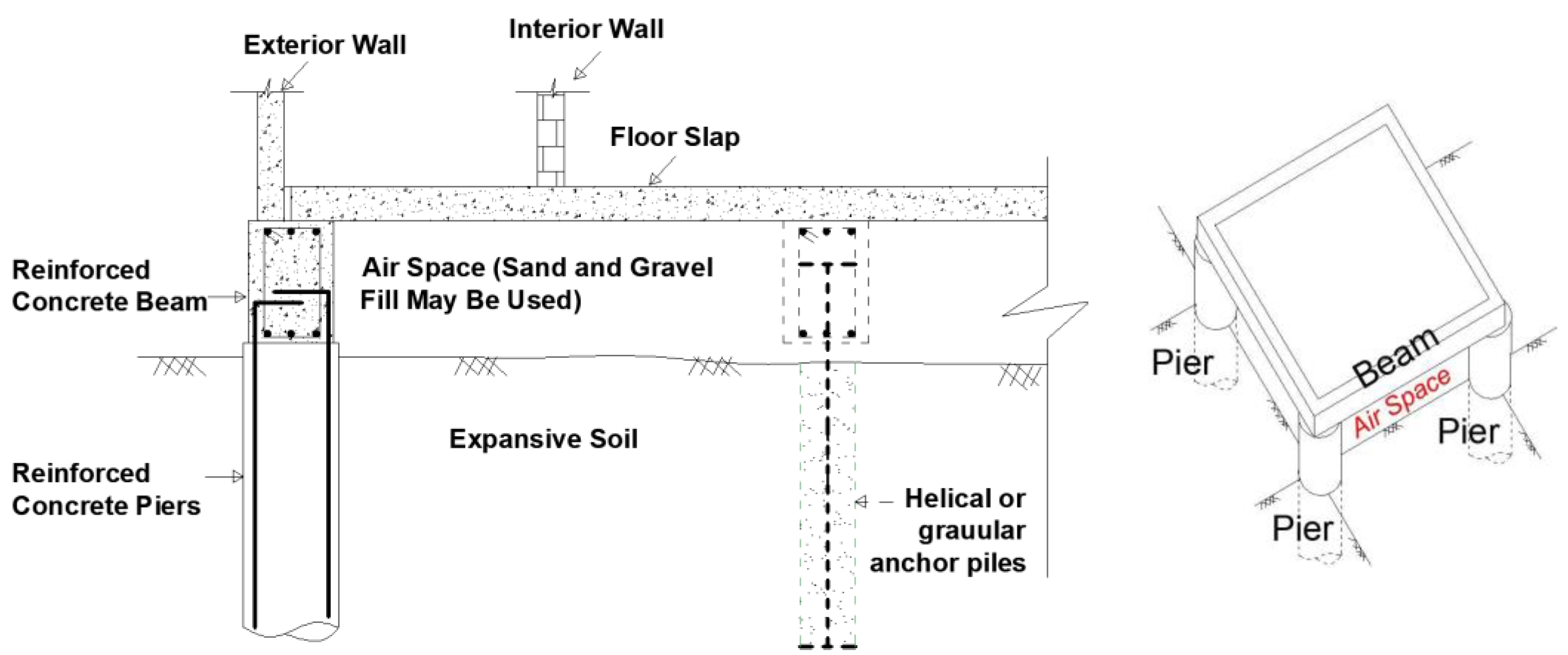
Pier, helical pile, or Granular anchor pile and beam (Figure 2)Isolate structure from expansive movement by
mitigating swell using anchoring to create stable layers
Utilized in a wide range of soils; effective in high-swell potential soilsThe design and construction processes are relatively complex. Specialized contractors are required.
Raft or
stiffened raft
Protects the structure from differential settlements by providing a rigid foundation.Reliable on soils with a moderate swell potential; no special building equipment is required.Only works for building relatively simple layouts; comprehensive construction quality control is required.
Modified continuous perimeter footing or deep trench fill foundationsSame as raft or stiffened raft foundation—includes stiffened perimeter beams.No specialized equipment is required for this simple construction.Ineffective in highly expansive soils or tree-influenced zones.
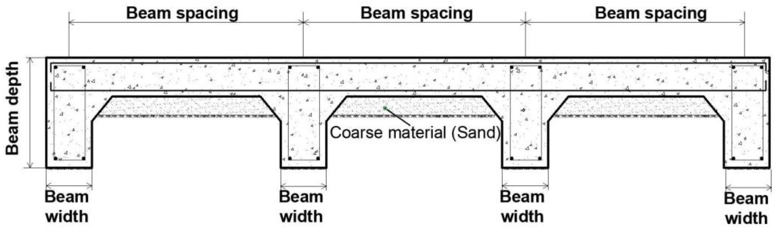
Table 5. Beam spacing and depth according to the type of mat (compiled based on [26]).
Type of MatBeam Depth, cmBeam Spacing, m
Light40 to 506 to 4.5
Medium50 to 654.5 to 3.6
Heavy65 to 754.5 to 3.6
Table 6. The most popular types of pile foundations (compiled based on [26]).
ClassificationTypeDescription
DisplacementTimber
Precast concrete
Steel circular/rectangular
Tapered timber/steel
Driven piles have a solid circular or rectangular cross-section or a closed bottom end. Piles that have been hammered or jacked into position
Small displacementPrecast concrete
Prestressed concrete
Steel H section
Steel circular/rectangular
Screw (helical pile)
Open-end cylinder, rectangular, H section, or screw configuration pile with a small cross-section
NondisplacementDrilled shaft
Tubes filled with concrete
Precast concrete
Injected cement mortar
Steel section
Granular anchor pile
Piles of concrete are placed in open boreholes drilled by using a rotary auger,
baling, grabbing, airlift, or reverse circulation methods.
Table 7. Problem dimensions in this study.
Diameter (D)
(m)
Granular Anchor Pile Length (L)
(m)
Cap Width (B)
(m)
0.641
7
10
Table 8. Soil properties in finite element analysis.
Model ParameterExpansive Soil
(Undrained Behavior)
Sand
(Drained Behavior)
Granular
(Drained Behavior)
γ u n s a t (kN/m3)15.31619
γ sat (kN/m3)18.41921
E 50 r e f (kN/m2)500040,00050,000
E o e d r e f (kN/m2)500040,00050,000
E u r r e f (kN/m2)15,000120,000150,000
C′ (kN/m2)170.10.1
φ ′ (°)203738
ψ (°)078
ν u r (−)0.30.250.2
m (−)10.50.5
Table 9. Steel and concrete properties considered in finite element analysis.
Model ParameterHelix Plate
(Linear Elastic)
Shaft (Linear Elastic)Concrete Foot
(Linear Elastic)
Unit weight (kN/m3)787824
E (kN/m2)200,000,000200,000,00030,000,000
v (−)0.30.30.15
Thickness (m)0.01-0.5
Dimension (m)-0.1 × 0.11 × 1
Table 10. Parameters of disturbed sand and clay after the implementation of a helical pile.
Model ParameterExpansive Soil
(Undrained Behavior)
Sand (Drained Behavior)
γ u n s a t (kN/m3)15.316
γ sat (kN/m3)18.419
E 50 r e f (kN/m2)350020,000
E o e d r e f (kN/m2)350020,000
E u r r e f (kN/m2)10,50060,000
C′ (kN/m2)80.1
φ ′ (°)1930
ψ (°)01
ν u r (−)0.30.25
m (−)10.5
Table 11. Pullout load comparison between HP and GAP.
L (m)GAP Pullout Load (kN)HP Pullout Load (kN)(GAP-HP)/HP
(%)
415913517.8
727122222.1
1031525324.5
Table 12. Compressive load resistance of GAP and HP.
L (m)GAP Capacity (kN)HP Capacity (kN)(GAP-HP)/HP (%)
42412304.8
729026210.7
1031528410.9
Table 13. Heave values of the two types of piles as well as the percentage of heave reduction for each type.
Reduction Heave of Helical Pile (%)Reduction Heave of Granular Anchor Pile (%)Heave (m)Length (m)Case
Unreinforced SoilHelical PileGranular Anchor Pile
54.951.70.2680.1210.1294Case-1-
92.692.20.2680.0200.0217
94.093.00.2680.0160.01910
78.671.70.2600.0550.0734Case-2-
95.195.70.2600.0130.0117
96.397.00.2600.0100.00810
Table 14. Comparison between piles considering the review and numerical study.
PropertyGranular Anchor PileHelical PileStraight Shaft PilesUnder-Reamed Piles
Pullout loadExcellentGoodFairGood
Downward loadFairPoorGoodExcellent
HeaveExcellentExcellentGoodVery good
Combining concrete elementsGoodGoodVery goodVery good
CostInexpensiveExpensiveModerately InexpensiveModerately Expensive
Damage during installationNo DamageExposed to damageNo damageNo damage
lateral loadsWeakWeakerGoodGood
Type of load transferTip resistance and skin frictionTip resistanceSkin friction and tip resistanceTip resistance and skin friction
Direction of installationVertical directionAll directionsVertical directionVertical direction
Installation timeInstalled with no cure time, allowing for quick project implementation.Installed with no cure time, allowing for quick project implementation.Concrete takes 2–4 weeks to cure.Concrete takes 2–4 weeks to cure.
Environmental EffectsSteel can be removed and reused, reducing waste.Steel can be removed and reused, reducing waste.Non-reusable after installation.Non-reusable after installation.
Disclaimer/Publisher’s Note: The statements, opinions and data contained in all publications are solely those of the individual author(s) and contributor(s) and not of MDPI and/or the editor(s). MDPI and/or the editor(s) disclaim responsibility for any injury to people or property resulting from any ideas, methods, instructions or products referred to in the content.

