Article

Construction and Performance Evaluation of Polyurethane-Bound Porous Rubber Pavement (PRP) Trial Section in the Cold Climate

1
Department of Civil and Environmental Engineering, University of Waterloo, 200 University Ave W, Waterloo, ON N2L 3G1, Canada
2
Department of Civil Engineering, McMaster University, 1280 Main St W, Hamilton, ON L8S 4L8, Canada
*
Author to whom correspondence should be addressed.
Sustainability 2023, 15(3), 2413; https://doi.org/10.3390/su15032413
Submission received: 8 December 2022 / Revised: 9 January 2023 / Accepted: 25 January 2023 / Published: 29 January 2023
(This article belongs to the Special Issue Pavement Materials and Sustainability)

Abstract

:
Porous pavements are designed and used in current construction practices to address environmental and safety issues related to wet weather. Porous rubber pavement (PRP) is a novel porous pavement material consisting of recycled crumb tire rubbers, stone aggregates, and polyurethane binders. The higher permeability (up to 45% of air voids) of PRP and its composition offers excellent benefits to the urban hydrological system and environment. Due to its recent outset in the Canadian climate, its properties and performance are not yet investigated. This research investigates PRP’s properties and performance as pavement material through the construction of two trial sections incorporating three newly developed PRP mixes along with a Control Mix. Samples were obtained from the field and tested in the laboratory to determine the mechanical and durability properties, including indirect tensile strength, moisture-induced damage due to freeze-thaw cycles and permanent deformation. A field evaluation was also performed three times: right after construction, three weeks later and after seven months to determine stiffness, frictional properties, roughness and permeability. The results revealed that all PRP mixes exhibited excellent permeability and retained more than 68% of tensile strength after five freeze-thaw cycles. Although PRP showed significantly lower initial elastic modulus than conventional pavement material, ranging between 28 MPa to 59 MPa, in the springtime none of them went below 23 MPa. Material composition, site geometry and subgrade conditions were found to be the main factors influencing the field performance of PRP pavement.

1. Introduction

Rapid urbanization is part and parcel of modern civilization and leads toward covering permeable surfaces for new development. Thus, the seepage capacity of urban surfaces has declined and can lead to a noticeable distortion in the natural ecosystem [1]. To respond to the effect and mitigate the risk of increased surface runoff through construction, the use of porous pavement is becoming popular [2]. Porous pavements contribute significantly to reducing surface runoff and replenishing the groundwater table. In addition, it can address safety issues related to wet weather by reducing spray, splash and hydroplaning during rain and snow. Porous rubber pavement (PRP) is a novel addition to this type of pavement material. PRP consists of recycled crumb tire rubbers, stone aggregates and polyurethane binders and contains a higher percentage of air voids (up to 45%). Further, PRP replaces the use of virgin material by using recycled tires. Thus, the higher permeability of PRP and its composition can offer excellent benefits to the urban hydrological system along with its environmental advantages. However, there is very limited research, development, and information available on these systems. Although a few studies were identified from some European and Asian countries, they are also in the very initial stages of examining this material [3,4,5]. Moreover, the use of PRP has been added to contemporary Canadian construction practices very recently. PRPs are used in this climatic region on low-traffic roads and pedestrian walkways as a surface material. It should be noted that this application is in limited areas only. Due to its recent outset in the Canadian climate, its properties and performance as a pavement material are not investigated yet for this climatic condition. Hence, it is essential to understand the properties and performance of PRP from laboratory and field investigation before its widespread application in Canada.
Along with laboratory investigation and development, the construction of trial sections is critical to verify the material’s laboratory performance under actual conditions. Any pavement can perform differently in a natural ecological environment. Surrounding conditions, soil types, water quality, sub-surface layers, traffic load, etc., all work together to affect permeable pavement performance. For instance, if the pores of permeable pavement are partially saturated with water, hydromechanical interactions occur during traffic load and influence the durability of permeable pavement [2]. Further, many steps are involved in trial section construction, from preparing construction drawings to pouring the material. These steps and process clarify many issues, enrich construction knowledge and influence pavement performance.
Thus, extensive research was planned for both the laboratory and field to investigate and improve the properties and performance of PRPs in the Canadian climate. Prior research was conducted for preliminary field investigation, developing different compositions of PRPs and testing their performance in laboratory facilities. This research is designed to investigate PRP’s properties and performance from two field applications for selected mixes. Additionally, samples were prepared from field mixes to investigate the properties and durability of field mixes under laboratory conditions, and to determine their deviations from laboratory mixes.

2. Trial Section Construction

2.1. Location

The trial section is located at 1400 Greenwood Hill Rd, Wellesley, ON N0B 2T0. The location is situated within the Township of Wellesley. It is a north-western pastoral township of the Regional Municipality of Waterloo in Ontario, Canada [6]. It is about 23 km from the City of Waterloo. Figure 1 and Figure 2 show the location’s bird’s eye view and view from the entrance, respectively.
An agricultural and farm product manufacturing and distributing company is located at the site. Other small rental businesses are also operated at the site.

2.2. Site Selection

Two sites were selected at this location. Site A is the dedicated parking area for the businesses on site. Mostly, cars are parked there during peak hours. Site B is the driveway to the drop-off and pickup point. This site is a sloped driveway leading towards the loading-unloading dock. All sorts of vehicles use this driveway, from small cars to heavy trucks. However, the vehicles’ driving speed is slow on the driveway, ranging between 30 km/h to 40 km/h. Figure 3 and Figure 4 show the surroundings of Site A and Site B.

2.3. Weather Conditions

The trial sections were constructed on 2 October 2021. At 8:30 am, the temperature was 15 °C. The wind speed was 14 km/h (SW), and the wind gust was 25 km/h. By the time of construction at 10:30 am, the temperature had reached 19 °C. The wind speed was 15 km/h (SW), and the wind gust was 27 km/h.

2.4. Planning before Construction

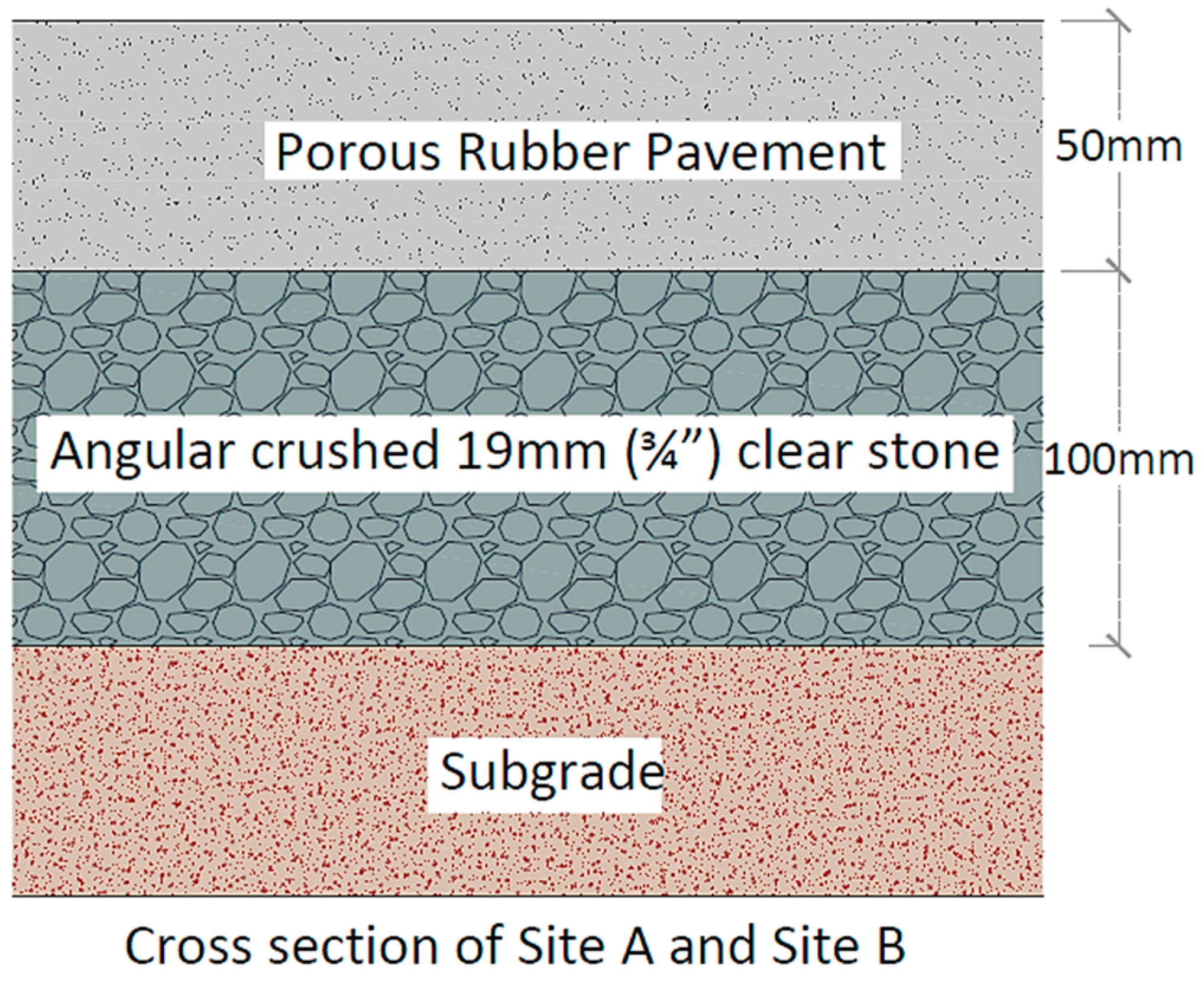
Before construction, Site A and Site B plans were prepared with all necessary dimensions. It was also essential for the construction workers to obtain the exact measurements to prepare the ground for construction. Cross-sectional drawings for the pavements were also produced. Figure 5 and Figure 6 show the plan for Site A and Site B, respectively. Figure 7 shows the cross-section of the trial section.

2.5. Mixes Used for Placement

PRP materials consist of stone aggregates, rubber aggregates and polyurethane binder. Table 1 shows the basic properties of the components used in this research.
Three new mixes with varied compositions and the Control Mix were employed to build the different segments of the trial sections. These new mixes were chosen based on their mechanical performance and durability as determined by a series of lab tests in the prior research. The mixes that were selected for the trial section are shown in Table 2.

2.6. Weather Station Installation

A weather station was installed the day before work began for construction. A suitable location for the weather station was selected to receive maximum sun, rain, and wind exposure. It was installed on a concrete block close to Site A in the middle of vacant land that is seasonally used for growing kitchen vegetables (as shown in Figure 8).

2.7. Subgrade and Base Preparation

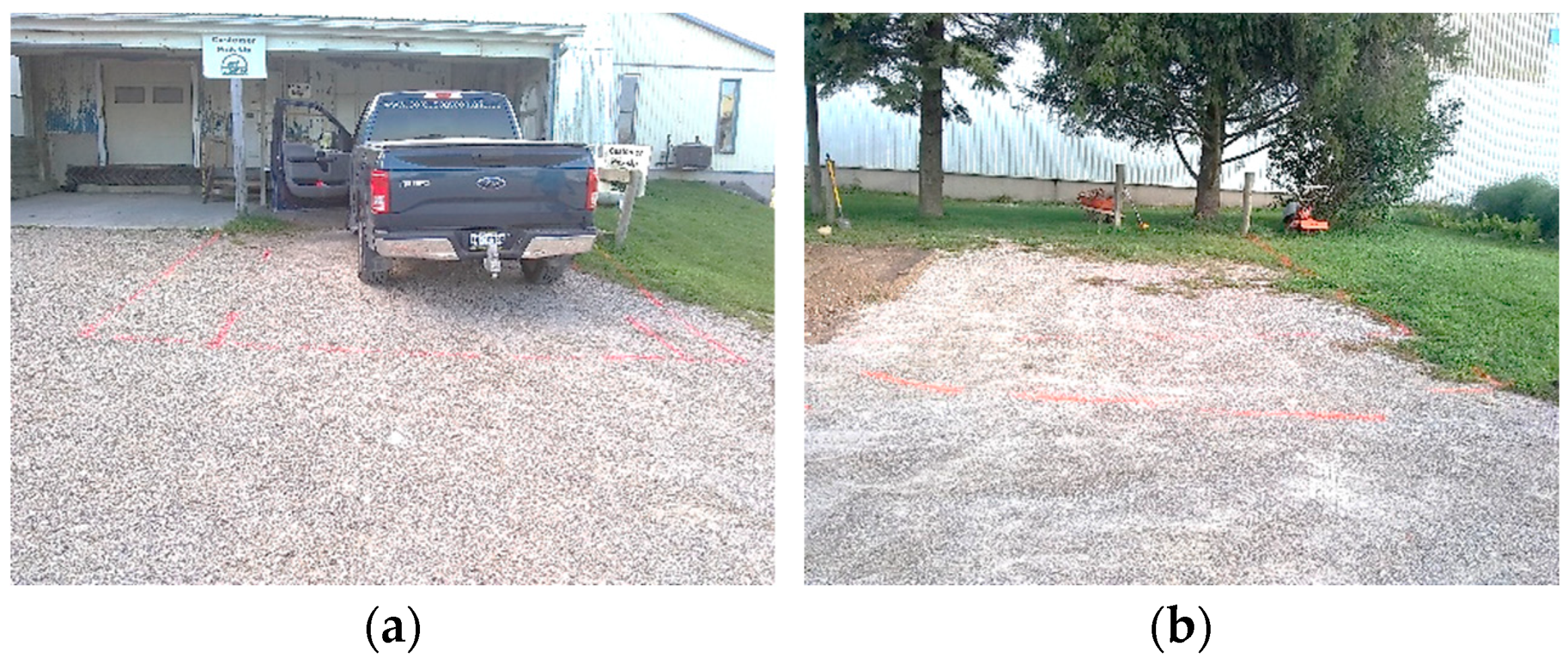
Following the drawing, section outlines were marked on Site A and Site B, as shown in Figure 9. Then, using an earth excavator, the existing surface layers were removed up to 150 mm (6 inches).
After removing the surface layer from both sites, the subgrade soil was collected for CBR (California Bearing Ratio) testing. The CBR test is essential to determine the soil’s stability and strength. Then, the uneven subgrade was further levelled manually. After levelling, an angular crushed stone of 19 mm was placed to the thickness of 100 mm and compacted with a small compactor, as shown in Figure 10. Then, plastic edges were placed on different sections with pegs to create different segments.

2.8. Construction Technique, Equipment and Placement

After preparing the subgrade and base layers, the different mixes were prepared on-site. Each mix was prepared for both sites at the same time to maintain the consistency of the mix. Mix preparation followed a consistent method. First, stone and rubber aggregates were measured and mixed using a medium-sized mixer for 60 s. After 60 s, the polyurethane binder was added according to the measurement. Then all the materials were mixed again for 180 s. Finally, loose mixes were carried to the site using a dumper. The processes are shown in Figure 11.
After pouring the loose mixes on the relevant sections, the mixes were spread over the entire area with a trowel and screed to achieve a thickness of 50 mm. Then, using a flat plate with vibration, the surface was smoothened further. Later a small amount of mist was applied to the surface to accelerate the curing process. After misting, the surface was again smoothened with a roller. PRP is a self-compacting material, and crumb rubber aggregate possesses elastic properties. Thus, the external vibration to compact the material has little effect on reducing air voids. However, vibration enhances the bonding among different components. Therefore, as planned, the vibration time was increased more than regular practice. Then, the surface was left undisturbed for curing. Figure 12 shows several construction steps.

2.9. Preparing Samples for Lab Testing

During the construction of the sections, samples were also prepared for further lab testing. The sample preparation followed the procedure developed in prior research, as shown in Figure 13. Ideally, lab test results show the materials’ consistent and actual properties. However, the material’s performance can be different during actual construction due to differences in workmanship, construction procedure, ambient environment, handling of large amounts of materials, etc. Thus, it is crucial to prepare samples during trial section construction and test them in the lab facilities. This helps to identify the performance gaps and room for improvement during construction.

2.10. Opening for Traffic

The trial sections were kept undisturbed for 24 h to be cured after completion of construction. Then, before entirely opening for traffic, the pavements were tested to evaluate their initial condition and performance. Finally, the sections were opened for all sorts of traffic after being fully cured.

3. Lab Testing of Samples Prepared on the Construction Site

3.1. Methodology for Laboratory Testing

3.1.1. Laboratory Compaction Characteristics of Subgrade Soil

The laboratory compaction method, ASTM D698, was used to investigate the relationship between water content and dry unit weight of soil. Method C was used in this test based on the soil’s gradation. In this case, 30% or less soil material was retained on the 19 mm sieve by mass. A mould of 152.4 mm was used to compact the soil into three layers. On each layer, 56 blows were applied [7].

3.1.2. California Bearing Ratio (CBR) Test

The standard test method ASTM D1883-16 was followed to examine the subgrade soil’s California Bearing Ratio (CBR). This method determines the strength of subgrade soil with a maximum particle size of less than 19 mm. It also investigates soil’s linear swelling after soaking with water [8].

3.1.3. Indirect Tensile Strength

The Indirect Tensile Strength (ITS) test was conducted following the standard AASHTO T32207. ITS was performed using 50 mm high and 150 mm diameter samples [9]. The estimated resistance capacity of the sample is considered as the material’s tensile strength [10]. Thus, the breaking or the highest force observed on the sample was obtained to calculate the material’s tensile strength. The following equation was used for the calculation.
S t = 2000 × P f π × b × D
where St = Tensile strength of specimen, kPa
  Pf = Maximum load observed for specimen, N
  b = Thickness of the sample, mm
  D = Diameter of the sample, mm

3.1.4. Moisture-Induced Damage Test

The moisture-induced damage test was conducted for the trial section samples. Two groups of samples involved in this test had the same properties. The first group of samples was tested for ITS without any conditioning. The second group of samples was conditioned with five freeze-thaw cycles (freezing at −18 °C and thawing at 60 °C) and then tested for ITS. Then, the calculated numerical indices of retained indirect tensile properties indicated the moistureinduced damage to the material [11]. A modified test method was followed for freeze-thaw conditioning of the sample, as developed in earlier research. In this modified method, a partial vacuum of 660 mm (26 inches) Hg was applied for 10 min to saturate the samples, which were then submerged in water during freezing cycles to maintain saturation. According to the standards, the retained tensile strength (Tensile Strength Ratio or TSR) of at least 80 percent indicates good resistance to moisture-induced damage [11,12,13].
From the test results, the TSR was calculated using the following equation.
T S R = S 2 S 1
where S1 = Average tensile strength of the dry samples
  S2 = Average tensile strength of the conditioned samples

3.1.5. Hamburg Wheel Tracking Test

The Hamburg wheel tracking test was conducted following AASHTO T324-17 to investigate the permanent deformation (rutting) and moisture susceptibility of the trial section samples. The rate of permanent deformation from moving concentrated loads can be derived for the submerged samples. The test temperature was 53 ± 1 °C. In addition, moisture-induced stripping was calculated from the samples’ material loss. Premature failure of the sample due to weakness of aggregate structure, low binder stiffness or moisture damage can be determined through this test [14].

3.2. Lab Testing Results

3.2.1. Determination of Moisture Content for Subgrade Soil

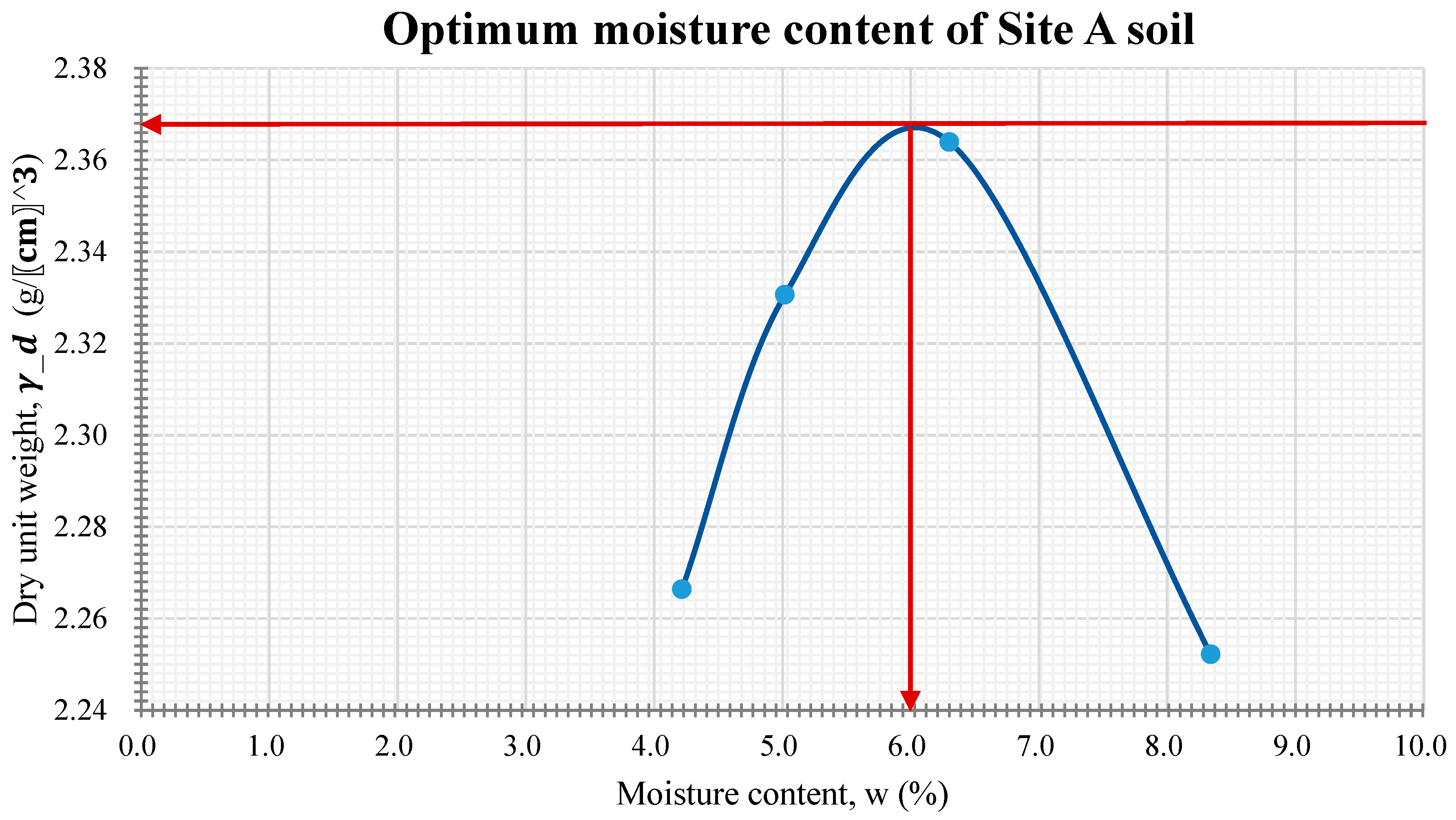
The optimum moisture contents of the subgrade soil of both sites were obtained using the laboratory compaction method ASTM D698 (Method C). The test steps are shown in Figure 14. The obtained optimum moisture content information was used to prepare samples for CBR testing. The optimum moisture content values for Site A and Site B soils were found to be at 6% and 5.9%, respectively (as shown in Figure 15 and Figure 16).

3.2.2. California Bearing Ratio (CBR) of the Subgrade Soil

The CBR value for subgrade soil explains the bearing capacity of the subgrade. The procedure of the test is shown in Figure 17. The subgrade soil types of Site A and Site B are shown in Table 3. The subgrade soil of Site A was coarse-grained soil falling into the category of SM (sands with fines). It contained sands with an appreciable amount of fines. In addition, silty sands and sand-silt mixtures are also found in this type of soil, and the fines can be non-plastic or characterized by low plasticity.
The subgrade soil of Site B falls within the category of SW (clean sands). The SW is coarse-grained soil with clean sand and slight fines. Well-graded sands, gravelly sands and little or no fines are found in this type of soil. A wide range also characterizes this soil type in terms of grain sizes and substantial amounts of all intermediate particle sizes [15].

3.2.3. Indirect Tensile Strength

In a cold climate, low-temperature cracking and deformation are critical factors with respect to the durability of pavement material. However, the pavement material’s tensile strength could be one indicator of durability against low-temperature cracking [10]. Among the mixes used in the trial sections, New Mix 3 showed the highest tensile strength, 682.4 kPa. However, this result was higher than the previously found results in laboratory mix samples (547.8 kPa). Table 4 shows the result of the indirect tensile strength test. The Control Mix showed the lowest tensile strength, i.e., 299.3 kPa. New Mix 3 contained a higher percentage of binder (12%), which influenced the increase in tensile strength. New Mix 2 also showed a relatively higher tensile strength of 518.7 kPa. New Mix 2 contained the highest percentage of stone aggregates (75%), but the lowest percentage of binder (7.5%). A higher stone aggregate percentage probably contributed to this strength. The factorial analysis in the prior research revealed that both stone aggregates and binder percentages influence the tensile strength of the PRP material. It showed that a 10% increase in stone aggregates increased the tensile strength of the PRP material by 85.16 kPa. Further, an increase of binder by 2.25% increased the material’s tensile strength by 76.29 kPa.

3.2.4. Relationship between Indirect Tensile Strength (ITS) and Air Voids

Indirect tensile strength (ITS) and air voids exhibited a polynomial equation with a high R2 value of 0.98 after plotting the result. It was found that the increase in air voids in the sample gradually decreased the material’s tensile strength, as shown in Figure 18. Furthermore, the regression model showed that the adjusted R2 value was 0.93, along with a P-value of 0.15 at an alpha level of 0.05, which means the interaction between ITS and air void was not statistically significant.

3.2.5. Moisture-Induced Damage Test due to Freeze-Thaw Cycles

Moisture-induced damage is a common phenomenon for permeable pavement. Water penetrates through the pore structures and gets saturated quickly for the time being if the pores are clogged. In a cold climate, the freeze-thaw cycles further deteriorate this condition and cause premature pavement damage [2,16]. The moisture-induced damage in the PRP mixes was obtained from retained tensile strength in the samples after conditioning with five freeze-thaw cycles, as shown in Table 5. The retained tensile strength for all the mixes was found to be more than 70%, except for the New Mix 2. Higher retained tensile strength in samples could be correlated to the higher percentage of rubber aggregates and binders in the mixes. The Control Mix showed the highest retained tensile strength (80%) since it contained the highest percentage of rubber aggregates (45.25%) and a higher percentage of binder (9.5%). The New Mix 3 also showed a higher retained strength (76%) since it contained 33% rubber aggregates and 12% binder. On the other hand, New Mix 2 contained the lowest percentage of rubber aggregates (17.5%) and binder (7.5%), thus showing the lowest retained strength. The retained tensile strength calculated for the New Mix 2 was 68%.

3.2.6. Hamburg Wheel Tracking Test Result

The rutting resistance of the PRP material was investigated through the Hamburg wheel tracking test. The average rutting results for different mixes ranged from 0.81 mm to 0.99 mm, as shown in Table 6, which indicated that all the mixes showed good rutting resistance compared to the conventional pavement material. The analysis of the rutting result indicated that from 0 cycles to 10,000 cycles, several temporary rutting occurred on the samples, as shown in Figure 19. However, this temporary rutting mostly disappeared after the removal of the wheel load from the samples. Material’s elastic properties due to rubber aggregates and the large percentage of air voids could probably explain this phenomenon. Hence, the samples got room for deflection under loading conditions by compressing the air voids. However, after the load’s removal, the material’s elasticity helped it return to its original condition.
Stripping-related abrasion was also obtained from the Hamburg wheel tracking test, as shown in Figure 20 and Table 7. Samples’ weights were measured before and after the testing and after the drying of the samples. However, right after the test, all the samples showed a higher weight than the initial weight. The increased weight was due to water absorption by the sample’s stone aggregates during the test. However, after drying the samples, a small amount of weight loss was observed as compared to the the initial weight. These weight losses ranged from 0% to 0.3%, indicating the mixes’ stripping-related abrasion. However, the New Mix 3 showed a 0.7% increase in weight even after drying the sample. The probable reason could be this mix’s higher percentage of binder and stone aggregates. Along with water absorption by the stone aggregates, binder components probably chemically changed under the wheel pressure and water, resulting in increased weight. However, this change was negligible.

4. Field Test on the Trial Section

4.1. Field Testing Methodology

4.1.1. Light Weight Deflectometer

A light weight deflectometer (LWD) was used to determine the deflection due to a falling weight that was held at a constant height by a release mechanism. First, the deflection value was measured using the falling weight that transmits the impact of the load to the pavement surface. Then, the stiffness modulus of the pavement was calculated using the deflection value [17,18].

4.1.2. British Pendulum Test (BPT)

A British Pendulum Tester was used to measure the energy loss when its sliders were propelled over the pavement’s surface. A higher British Pendulum Number (BPN) is related to a more significant energy loss, which is associated with a higher frictional value of the pavement [19,20]. However, BPT can only measure the frictional properties at low speeds [21]. All the frictional values were measured after wetting the surface to obtain the results in wet conditions.

4.1.3. Rut Depth from Dipstick

The Dipstick is an inclinometer-based profile measurement device supported by two legs 305 mm apart. This piece of equipment measures the relative elevation difference of the legs. Usually, the Dipstick calculates the International Roughness Index (IRI) value [22,23,24]. However, the trial sections’ length was insufficient to determine the IRI value using this equipment. Thus, Dipstick calculated only the rut depths from the trial sections at different times.

4.1.4. NCAT Field Permeameter

NCAT Asphalt Field Permeameter was used to determine the trial sections’ water infiltration rate following ASTM C1701/C1701M. The permeameter’s bottom tire (cross-section area is 167.53 cm2) was used for testing. Four litres of water were poured on each point at least three times, and the average value was considered for calculation. According to the test standard ASTM C1701/C1701M−17a, at least three (3) test points are recommended for a test area of 2500 m2. Since the infiltration rate from each point is valid for the localized area, the average value was taken to determine the infiltration rate of the entire site [25].

4.2. Field Testing Schedule

The 1st field test was conducted on the trial sections from 4 October 2021 to 7 October 2021, right after construction but before fully opening for traffic. After the 1st field test, trial sections were fully opened for traffic. The 2nd field test was conducted on 23 October 2021, about two weeks after the 1st field test. Finally, the 3rd field test was carried out on 13 May 2022, about six months after the 2nd field test. Between the 2nd and 3rd tests, the trial sections experienced one winter. Schedule for field testing is shown in Table 8.

4.3. Weather Station Data

Weather data from the trial section construction time to the 3rd field testing is presented here. Figure 21 shows the daily maximum, minimum and average temperature from 15 September 2021 to 13 May 2022. The temperature ranged from 25 °C to −25 °C. Thus, the PRP pavement experienced a temperature difference of 50 °C from 1st to 3rd field testing. In addition, Figure 22 shows the rainfall data for the same period, indicating that in September 2021, the pavement received more precipitation.

4.4. Detailed Drawings for Field Testing

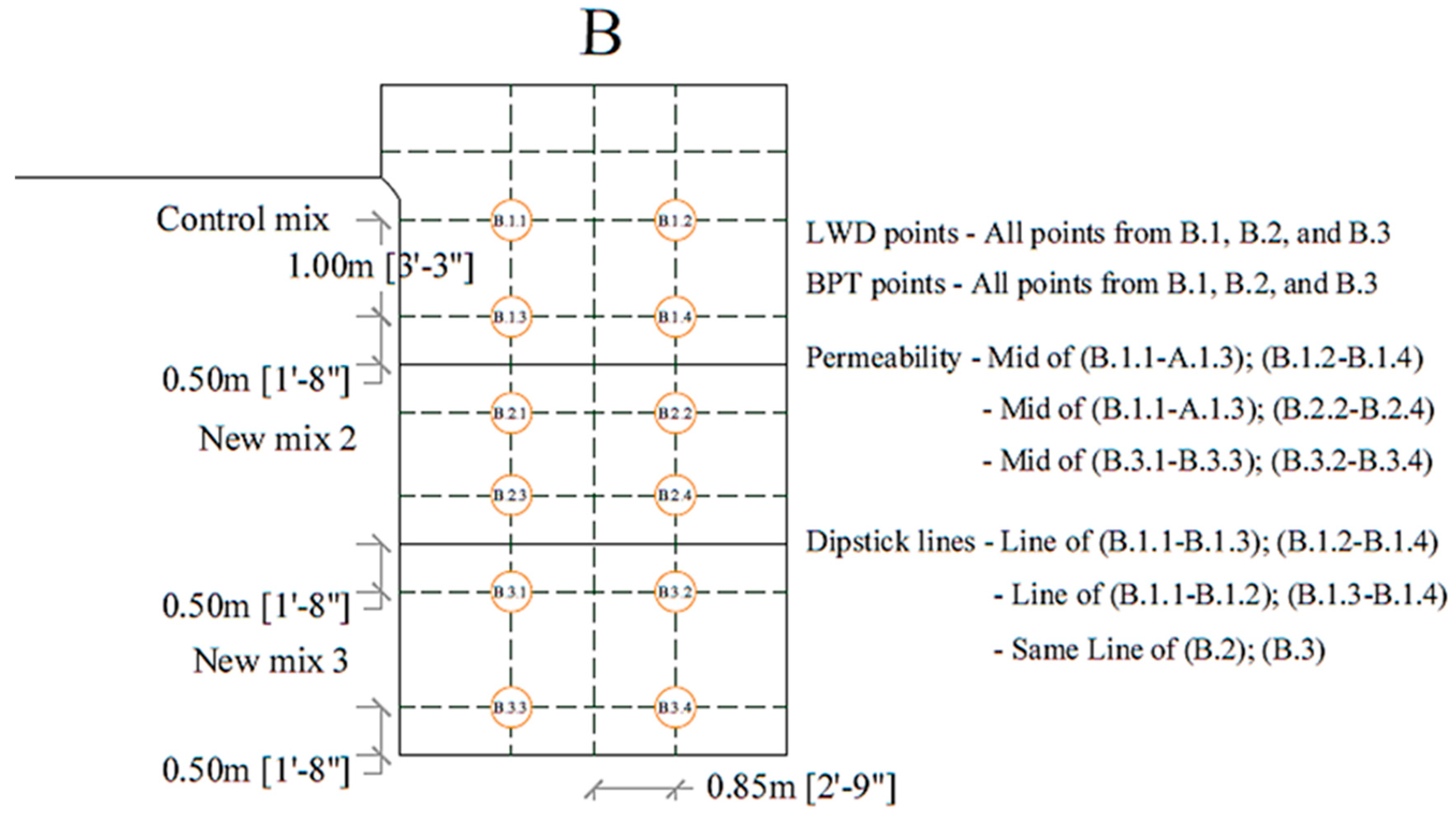
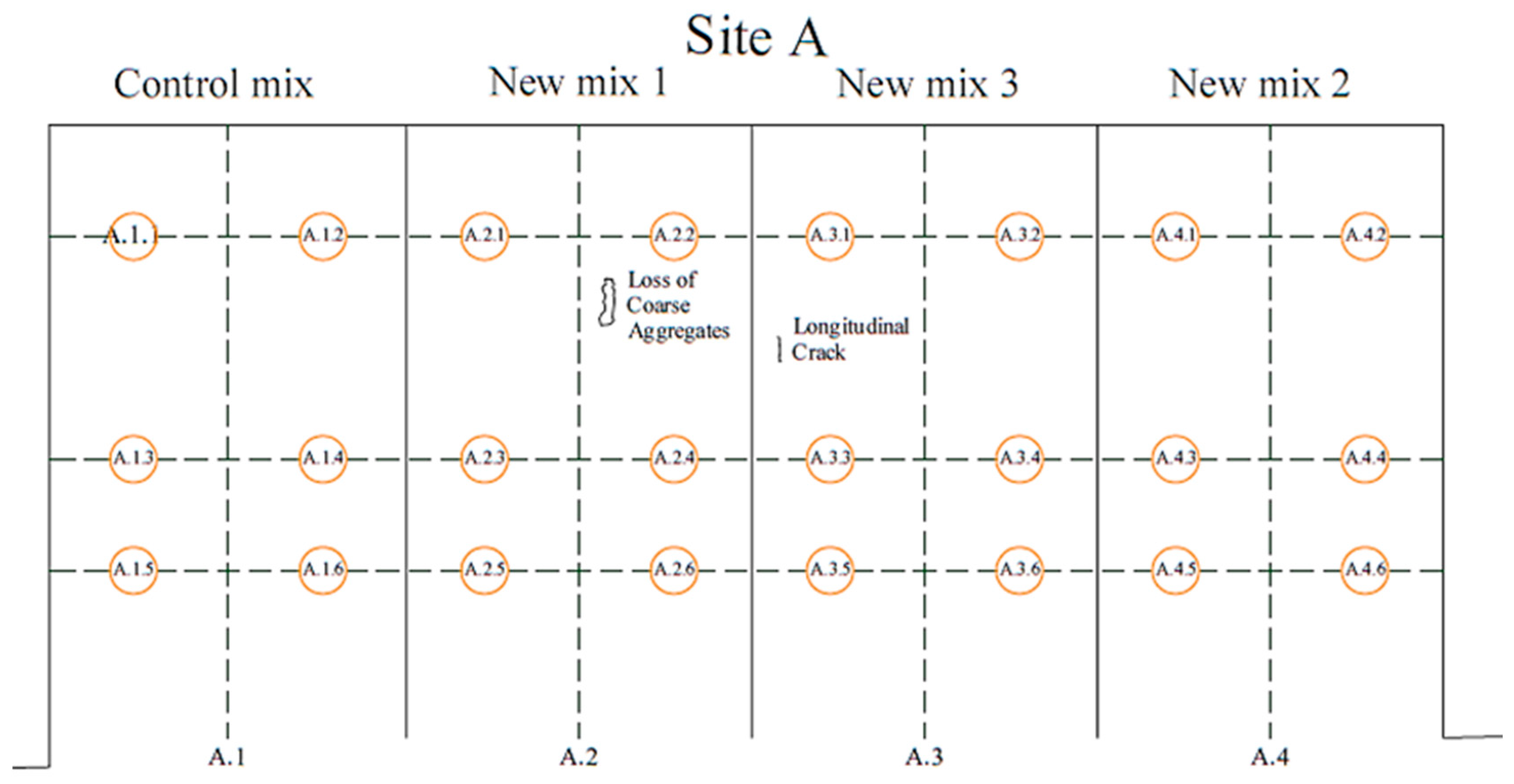
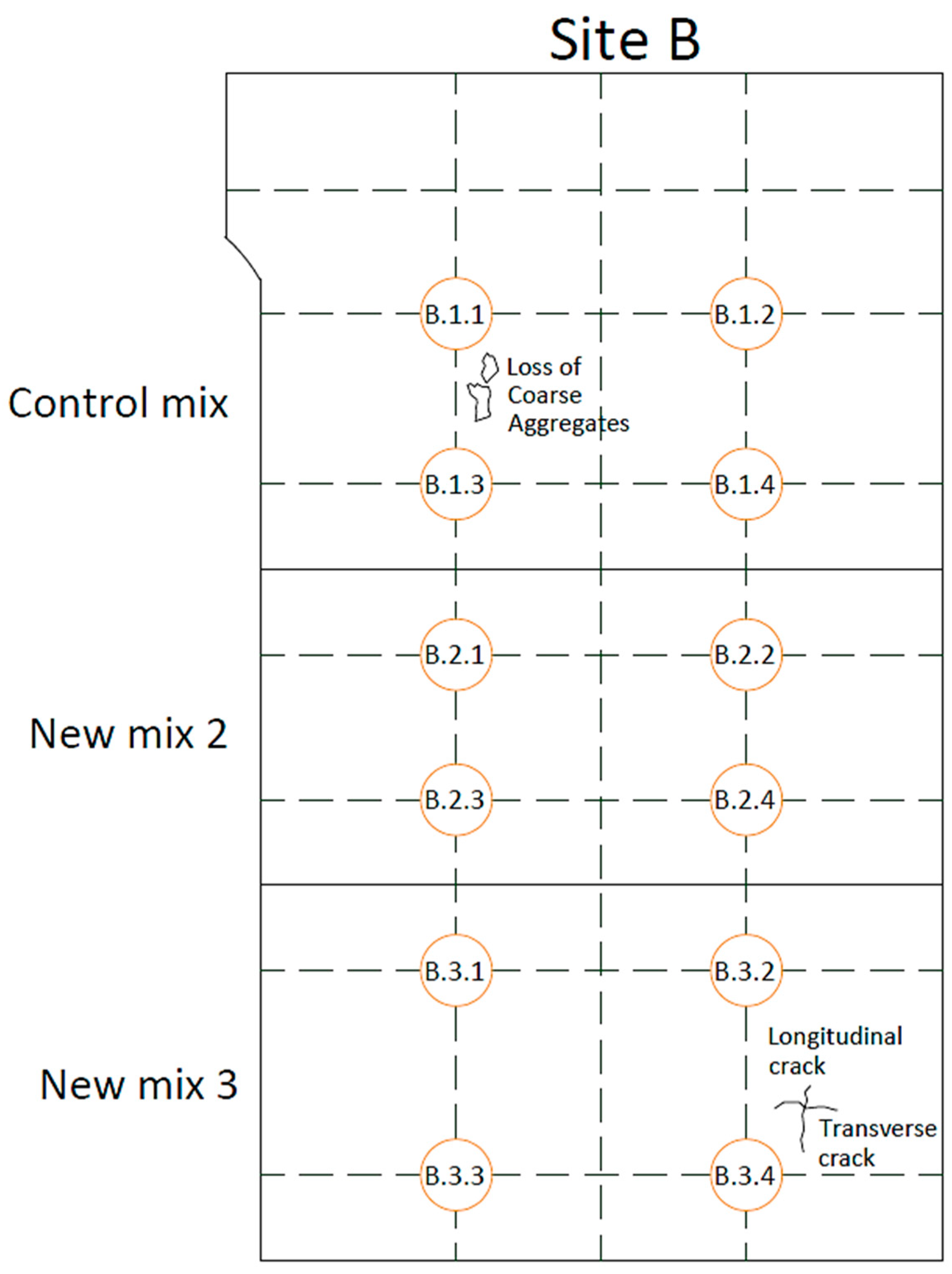
Detailed drawings of Site A and Site B are shown in Figure 23 and Figure 24, respectively. The figures also show the points that were tested during field testing.

4.5. Field Test Result

4.5.1. Light Weight Deflectometer (LWD) Results

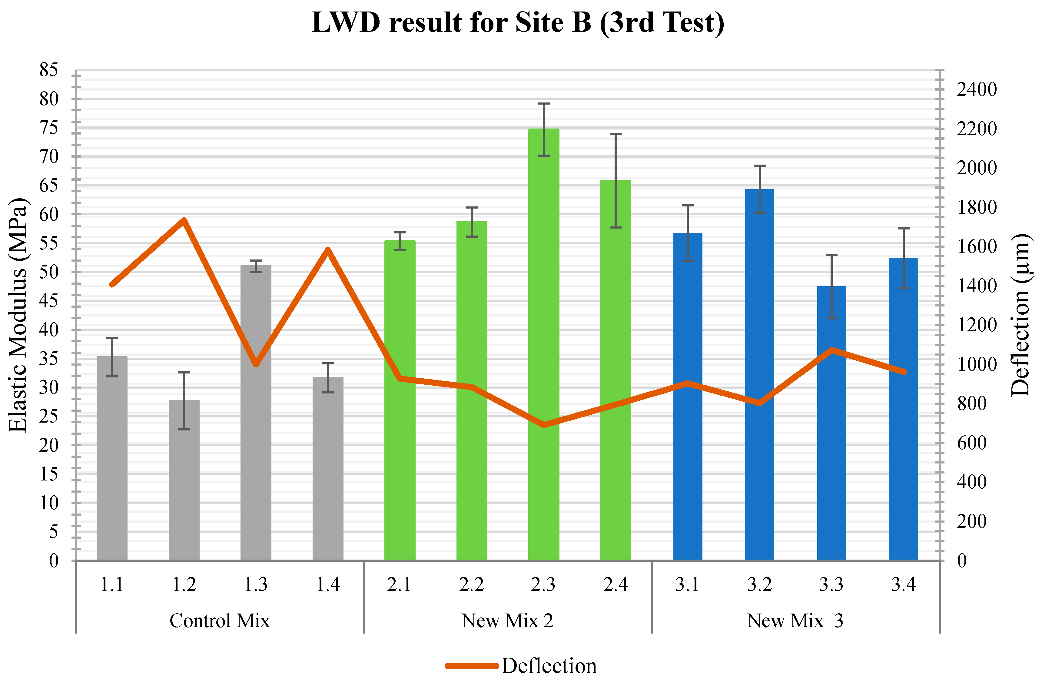
Site A and Site B were tested with LWD to measure the pavement’s deflection and elastic modulus. At Site A, six points were tested on each section, and at Site B, four points were tested on each section. As expected, where elastic moduli were found to be higher, deflection values were found to be lower and vice versa. The trial sections were tested with LWD three times after construction, as mentioned in Table 8. Among the three tests, a general trend was observed for all sections. During the 2nd test, elastic moduli were found to be higher than in the 1st. After the 1st test, vehicular traffic was fully opened, and further compaction on the pavement occurred under traffic loading. However, after the 3rd test, all the sections showed lower elastic modulus than in the 2nd. The timing of the 3rd test could probably explain the lower elastic modulus value. The 3rd test was conducted on 13 May 2022, in springtime. During the spring, subgrade soils are usually in their weakest condition due to thawing. Therefore, it was reflected in the pavement’s elastic modulus, which showed a lower elastic modulus during the 3rd test (Table 9 and Table 10; Figure 25, Figure 26, Figure 27, Figure 28, Figure 29 and Figure 30).
In addition to the test timing, the mixes with a higher percentage of rubber aggregates and binders compacted more than other mixes after opening for traffic. The Control Mix contained a higher percentage of rubber (45.25%) and binder (9.5%); thus, it compacted more after opening for traffic, resulting in a higher elastic modulus value during the 2nd test. Although initially, the average elastic modulus of the Control Mix was 36 MPa, during the 2nd test, it reached 45 MPa. New Mix 1 also contained a comparatively higher percentage of rubber aggregates (37.5%) and showed more compaction than other mixes (from 1st to 2nd test).
The LWD results differed for the same mixes at Site A and Site B. The reason could be the differences in the pavement’s sub-grade soil types and their strength. The CBR test revealed that the bearing capacity of the Site A (CBR 18.2%) subgrade is lower than the Site B (CBR 24.3%) subgrade. Thus, all mixes showed higher initial elastic moduli at Site B than at Site A. Further, New Mix 2 showed the highest elastic modulus at Site B despite containing a lower percentage of rubber aggregates (17.55%) and binder (7.5%), as shown in Table 10. The presence of hard rocks under this section probably contributed to this result.
Single-factor ANOVA analysis (with a confidence interval of 95%) was conducted on the LWD data collected at Sites A and B. The results for Control Mix, New Mix 1 and New Mix 3 at Site A showed that there was no significant effect of the time (from 1st to 3rd field test) on the elastic modulus of these mixes. That is proven by the P-value, as the obtained P-value is higher than 0.05. However, there was a significant effect of time on the elastic modulus of the New Mix 2 at Site A, as the obtained P-value was 0.032, which is less than 0.05. Also, there was a significant effect of time on the elastic modulus of the New Mix 3 at Site B (P-value is 0.00032).
Furthermore, a two-factor ANOVA analysis was conducted for Sites A and B. The two investigated parameters were the location and type of mixes. The obtained results showed that there was a significant effect of the location on the elastic modulus of the mixes. These differences were found in their initial stiffness and changes in stiffness over time.

4.5.2. British Pendulum Test

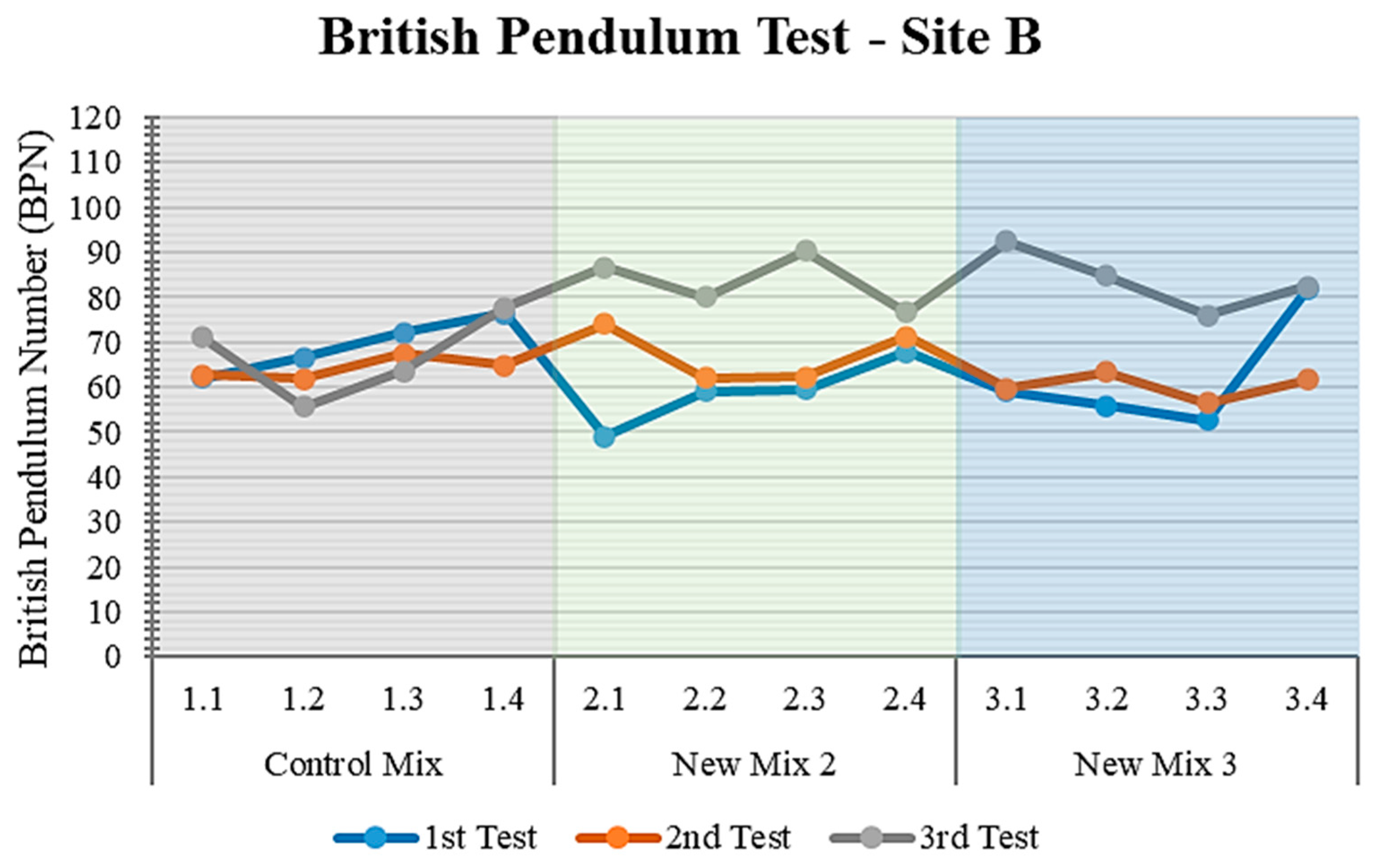
British Pendulum Numbers (BPN) for different sections were obtained from the British Pendulum Test. A higher BPN is related to a more significant loss of energy and higher friction value [20]. The measured frictional property of the pavement surface is associated with the micro-texture of the pavement surface [19]. Additionally, the Ministry of Transportation Ontario (MTO) recommended that the minimum value for pavement surface friction should be 30 BPN [20]. The results from the 1st to the 3rd field test showed that all the sections met this MTO requirement, exceeding the 30 BPN threshold. However, very high BPN values were obtained for several sections, which were associated with surface ravelling and particles’ movement from the surrounding areas. Hence, surface ravelling and particles’ movement from the vicinities can threaten the pavement’s durability.
Additionally, all the sections showed a common trend from the 1st to the 3rd test. Higher BPN values were obtained for all the sections during the 1st test, whereas the values were reduced in the 2nd. This reduction was because the PRP surfaces were compacted and polished further by the vehicular traffic after the 1st testing, which probably smoothened the pavement surface. However, during the 3rd test (in spring, after seven months of construction), surfaces ravelled and loose particles were transported from the site’s surroundings, increasing the BPN number again. The mixes with a higher percentage of stone aggregates and binders showed lower frictional values than those with a lower percentage of binder and a higher percentage of rubber. The Control Mix showed the highest BPN values (73 at Site A and 69 at Site B) since it contained a higher percentage of rubber aggregates (as shown in Table 11 and Table 12, Figure 31 and Figure 32). On the other hand, the New Mix 2 contained the highest percentage of stone aggregates (75%) and binder (12%), resulting in lower BPN values (60 at Site A and 59 at Site B).
Single-factor ANOVA analysis (with a confidence interval of 95%) was conducted on the BPT data collected at Site A and Site B. The results showed that there is no significant effect of the time (from the 1st test to the 3rd test) on the BPN values of the Control Mix, New Mix 2 and New Mix 3 at Site A. This was proven by the P-values, as the obtained P-values were higher than 0.05. However, there was a significant effect of time on the BPN value of the New Mix 1, as the obtained P-value was 0.003, which is less than 0.05. Further, the time factor had no significant effect on the BPN value of the Control Mix (P-Value 0.58) at Site B. However, the time significantly affected the BPN value of New Mix 2 and New Mix 3 at Site B (as the P-value was less than 0.05).
Furthermore, a two-factor ANOVA analysis was conducted for Sites A and B. The two investigated parameters were location and time. The results showed that the location factor did not significantly affect any mixes in their changes in BPN number over time.

4.5.3. Rut Depth from Dipstick

The International Roughness Index (IRI) is calculated automatically from recorded Dipstick measurements. However, trial sections were very small to calculate IRI using the Dipstick. IRI can only be calculated if at least 37 readings (minimum 9.25 m) can be obtained from the Dipstick. Therefore, only the average rut depth was possible to calculate using the Dipstick. Rut depths were calculated for Site A and Site B during the 1st and 2nd tests. Initial rut depths on Site A for different mixes ranged from −7.0 mm to −8.7 mm (Table 13 and Figure 33). For Site B, this range was −5.8 mm to −10.7 mm (Table 14 and Figure 34). The probable reason for this initial rut depth could be the workmanship, the site’s slopes and the undulating surface.
After fully opening for traffic, greater rut depths were found on each section under the wheel paths. These rut depths ranged from −22.5 mm to −26.0 mm for Site A and from −19.6 mm to −24.4 mm for Site B. Hence, compaction occurred under the wheel path, resulting in a larger rut depth.
A single-factor ANOVA analysis was conducted on the rut depths data collected at Site A and Site B (with a confidence interval of 95%). The result showed that rut depths at Site A for different mixes were changed significantly (P-value was less than 0.05) with time (between 1st and 2nd test). In contrast, the rut depths on Site B for different mixes did not change significantly between the tests. The probable reason could be the sites’ location and differences in the stiffness of the subgrade soil. Table 3 showed that the bearing capacity of the Site A subgrade soil was lower than that of Site B. In addition, a two-factor ANOVA analysis was conducted for Site A and Site B. The two investigated parameters were location and time. The result showed that all the mixes were performed similarly at both sites (P-value is above 0.05).

4.5.4. NCAT Field Permeameter

The permeability of different sections at Site A and Site B was tested three times (right after construction, three weeks after construction, and seven months later). Sections on both sites showed a common trend during these three tests. All sections showed more permeability in the 2nd test than the 1st test at both locations, except for New Mix 3. It is assumed that all the sections showed a certain permeability right after construction, before opening for traffic, based on the types of mixes. However, after three weeks of construction, due to environmental effects, traffic loading and interaction among the components, internal connectivity could have been changed, and new voids formed. Hence, the permeability of the sections was increased during the 2nd test. However, the New Mix 3 contained the highest percentage of binder (12%), probably resulting in greater compaction, reducing the interconnected air voids. Furthermore, the changes in the permeability of the sections at Site A and Site B differed in the 3rd test.
The permeability of the Control Mix and the New Mix 1 at Site A further increased in the 3rd test. In contrast, the permeability of the New Mix 2 and the New Mix 3 at Site A decreased in the 3rd test (Table 15). The probable reason could be the expansion of existing voids or the creation of new voids in the Control Mix and the New Mix 1 after winter. However, more compaction or clogging probably occurred in the New Mix 2 and the New Mix 3 after the winter.
All the sections at Site B showed reduced permeability during the 3rd test (Table 16). This can be explained based on field observation. Site B was constructed on a slope and surrounded by an unpaved area with loose gravel. Thus, lots of dirt particles were transported to the site from the surrounding area, reducing the sections’ permeability. Even the lowest part of the site (section with the New Mix 3) was found to be fully clogged with debris in the 3rd test.
A two-factor ANOVA analysis was conducted for the permeability data collected at Site A and Site B. The result showed no significant difference in the performance of the mixes at Site A and Site B (the P-value is higher than 0.05 at an alpha level of 0.05). However, the permeability rates in the trial sections were significantly higher than the highest rainfall rate in Canada, which is 298.8 mm/h [26,27,28].

4.5.5. Surface Distress Evaluation

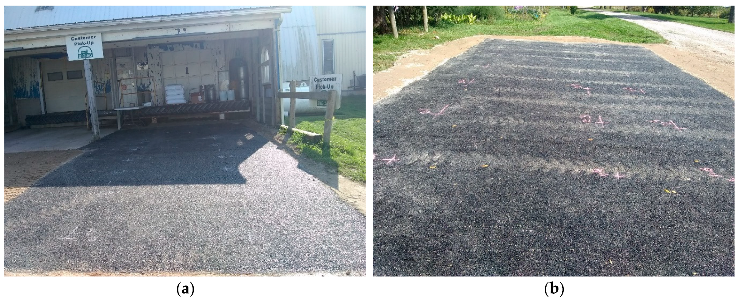
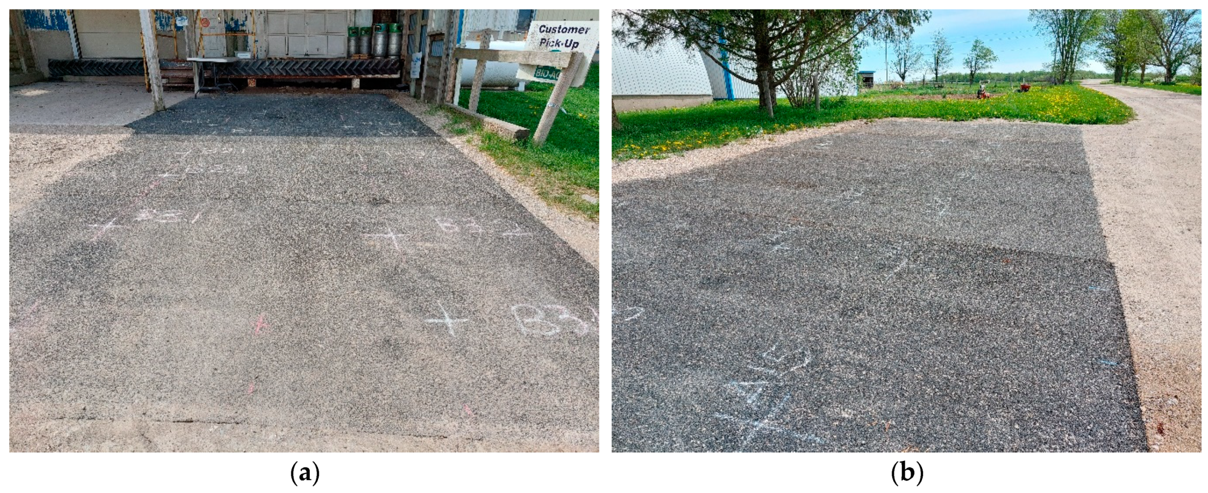
In three field tests, surface distress was evaluated for Site A and Site B. Visual inspection showed that there was no visible change from the 1st field testing to the 2nd at both sites, as shown in Figure 35 and Figure 36. However, during the 3rd field testing, as shown in Figure 37 (7 months after the construction), insubstantial surface distresses were observed at Site A and Site B, summarized in Table 17 and Table 18, respectively. At Site A and Site B, surface defects such as slight loss of coarse aggregate and minor ravelling were observed. In addition, very slight rutting was also found under the wheel paths. Furthermore, very small transverse and longitudinal cracks were observed at both locations. Surface distress evaluations are plotted in Figure 38 and Figure 39 for Site A and Site B, respectively.

5. Conclusions

This research aimed to investigate the properties and performance of PRPs from field construction before their large-scale use in the Canadian climate. Two trial sections were constructed using four different mixes. The properties investigated in the laboratory included indirect tensile strength, moisture-induced damage due to freeze-thaw cycles and permanent deformation, while the field investigation covered the pavement’s stiffness, frictional property, roughness, permeability and surface distress at different times in addition to the subgrade bearing capacity. The results are summarized below:
  • A higher percentage of stone aggregates and binder contents improved the indirect tensile strength of the PRP materials. In contrast, a higher percentage of rubber aggregates and binders improved the moisture-induced damage in the material.
  • All the PRP samples retained more than 68% indirect tensile strength after five freeze-thaw cycles.
  • In terms of permanent deformation, all PRP mixes showed good rutting resistance ranging between 0.81 mm to 0.99 mm.
  • Field evaluation revealed that mixes showed higher stiffness and lower rut depth on the field as soil bearing capacity increased.
  • Frictional values for all the mixes were found to be above the Ministry of Transportation Ontario (MTO) recommended lower threshold value, 30 BPN.
  • All PRP mixes showed excellent permeability, ranging from 28,368 mm/h to 45,605 mm/h, which is higher than the highest rainfall rate in Canada (298.8 mm/h).
It was observed that material composition, site geometry and existing subgrade conditions mostly influenced the performance of PRP pavements. Though a higher percentage of rubber aggregates improved the moisture-induced damage in the material, those mixes also showed higher stripping-related abrasion and ravelling. The abrasion loss and ravelling were further enhanced when the binder percentages were reduced in the mixes. Thus, the PRP mixes with higher percentages of stone aggregates and binder performed well. Besides, the overall procedure of trial section construction, the field and laboratory testing captured much practical know-how about the paving of PRP material and its performance outside the laboratory. It also provided essential knowledge to gain confidence with the preferred mix designs before widespread application in the Canadian climate.

Author Contributions

Conceptualization, T.K. and S.T.; methodology, T.K.; formal analysis, T.K.; investigation, T.K.; resources, T.K. and S.T; writing—original draft preparation, T.K.; writing—review and editing, S.T.; visualization, T.K.; supervision, S.T. All authors have read and agreed to the published version of the manuscript.

Funding

This research was funded by Mitacs Accelerate Proposal, Canada, and Stormflow Surfacing, Canada.

Institutional Review Board Statement

Not Applicable.

Informed Consent Statement

Not Applicable.

Data Availability Statement

Not Applicable.

Conflicts of Interest

The authors declare no conflict of interest.

References

  1. Törzs, T.; Lu, G.; Monteiro, A.O.; Wang, D.; Grabe, J.; Oeser, M. Hydraulic properties of polyurethane-bound permeable pavement materials considering unsaturated flow. Constr. Build. Mater. 2019, 212, 422–430. [Google Scholar] [CrossRef]
  2. Lu, G. Permeable Pavements: Hydraulic and Mechanical Investigations. Ph.D. Dissertation, RWTH Aachen University, Aachen, Germany, 2019. [Google Scholar]
  3. Kalman, B.; Biligiri, K.P.; Sandberg, U. Project PERSUADE: Optimization of poroelastic road surfaces in the laboratory. In Proceedings of the International Conference on Noise 2011, Osaka, Japan, 4–7 September 2011. [Google Scholar]
  4. Sandberg, U. PERS—A Historical Review; PERSUADE Final Seminar: Sterrebeek, Belgium, 2015. [Google Scholar]
  5. Wang, D.; Liu, P.; Leng, Z.; Leng, C.; Lu, G.; Buch, M.; Oeser, M. Suitability of PoroElastic Road Surface (PERS) for urban roads in cold regions: Mechanical and functional performance assessment. J. Clean. Prod. 2017, 165, 1340–1350. [Google Scholar] [CrossRef]
  6. 1400 Greenwood Hill Rd, Wellesley, ON N0B 2T0 2021. Available online: https://www.google.com/maps/place/1400+Greenwood+Hill+Rd,+Wellesley,+ON+N0B+2T0/@43.8449203,-81.4463225,9z/data=!4m13!1m7!3m6!1s0x882bfe907aebfedd:0x86c367507c11398!2s1400+Greenwood+Hill+Rd,+Wellesley,+ON+N0B+2T0!3b1!8m2!3d43.4829232!4d-80.75249!3m4!1s0x882bfe907aebfedd:0x86c367507c11398!8m2!3d43.4829232!4d-80.75249 (accessed on 20 September 2021).
  7. ASTM D698; Standard Test Methods for Laboratory Compaction Characteristics of Soil Using Standard Effort (12,400 ft-lbf/ft3 (600 kN-m/m3)). ASTM International: West Conshohocken, PA, USA, 2012.
  8. ASTM D1883; Standard Test Method for California Bearing Ratio (CBR) of Laboratory-Compacted Soils. ASTM International: West Conshohocken, PA, USA, 2012.
  9. AASHTO T322-07; Standard Method of Test for Determining the Creep Compliance and Strength of Hot Mix Asphalt (HMA) Using the Indirect Tensile Test Device. Test Specification. AASHTO: Washington, DC, USA, 2016.
  10. Lu, G.; Renken, L.; Li, T.; Wang, D.; Li, H.; Oeser, M. Experimental study on the polyurethane-bound pervious mixtures in the application of permeable pavements. Constr. Build. Mater. 2019, 202, 838–850. [Google Scholar] [CrossRef]
  11. AASHTO T283-07; Resistance of Compacted Hot Mix Asphalt (HMA) to Moisture-Induced Damage. AASHTO: Washington, DC, USA, 2011.
  12. ASTM D7064/D7064M; Standard Practice for Open-Graded Friction Course (OGFC) Mix Design. ASTM International: West Conshohocken, PA, USA, 2013.
  13. Kandhal, P.S. Design, Construction, and Maintenance of Open-Graded Asphalt Friction Courses; Information Series; National Asphalt Pavement Association: Lanham, MD, USA, 2002. [Google Scholar]
  14. AASHTO T324-17; Standard Method of Test for Hamburg Wheel-Track Testing of Compacted Asphalt Mixtures. AASHTO: Washington, DC, USA, 2017.
  15. USDA-NRCS. Part 631—National Engineering Handbook—Chapter 3—Engineering Classification of Earth Materials. In National Engineering Handbook; United States Department of Agriculture, Natural Resources Conservation Service: Washington, DC, USA, 2012. [Google Scholar]
  16. Huang, B.; Wu, H.; Shu, X.; Burdette, E.G. Laboratory evaluation of permeability and strength of polymer-modified pervious concrete. Constr. Build. Mater. 2010, 24, 818–823. [Google Scholar] [CrossRef]
  17. Elhakim, A.F.; Elbaz, K.; Amer, M.I. The use of light weight deflectometer for in situ evaluation of sand degree of compaction. Hous. Build. Natl. Res. Cent. 2014, 10, 298–307. [Google Scholar] [CrossRef] [Green Version]
  18. Mallick, R.B.; El-Korchi, T. (Eds.) Pavement Engineering—Principles and Practice, 3rd ed.; CRC Press, Taylor & Francis Group: Boca Raton, FL, USA, 2018. [Google Scholar]
  19. ASTM E303−93; Standard Test Method for Measuring Surface Frictional Properties Using the British Pendulum Tester. ASTM International: West Conshohocken, PA, USA, 2018.
  20. Pickel, D.J. Precast Concrete Inlay Panels: Rehabilitation Strategy for High-Volume Highways in Ontario. Ph.D. Thesis, University of Waterloo, Waterloo, ON, Canada, 2018. [Google Scholar]
  21. Saito, K.; Horiguchi, T.; Kasahara, A.; Abe, H.; Henry, J.J. Development of Portable Tester for Measuring Skid Resistance and Its Speed Dependency on Pavement Surfaces. Transp. Res. Rec. J. Transp. Res. Board 1996, 1536, 45–51. [Google Scholar] [CrossRef]
  22. Karamihas, S.M. Critical Profiler Accuracy Requirements. Draft Final Report; Report No.: UMTRI-2005-24; The University of Michigan Transportation Research Institute: Ann Arbor, MI, USA, 2005. [Google Scholar]
  23. Nazef, A.; Mraz, A.; Scott, S.; Whitaker, J. Evaluation of Surpro as a Reference Device For High-Speed Inertial Profilers; Report No.: FL/DOT/SMO/08-512; Department of Transportation (FDOT): Tallahassee, FL, USA, 2008.
  24. Pavement Interactive—Reference Desk. 2019. Available online: https://www.pavementinteractive.org/reference-desk (accessed on 5 October 2019).
  25. ASTM C1701/C1701M−17a; Standard Test Method for Infiltration Rate of In Place Pervious Concrete. ASTM International: West Conshohocken, PA, USA, 2017.
  26. Engineering Climate Dataset, IDF—Version 1.00. 2019. Available online: ftp://[email protected]/Pub/Engineering_Climate_Dataset/IDF/archive/IDF_v1.00/ (accessed on 9 January 2020).
  27. Kabir, T.; Oyeyi, A.G.; Al-Bayati, H.; Tighe, S. Performance evaluation of Porous Rubber Pavement (PRP) in the Canadian climate. In Proceedings of the TAC Conference & Exhibition, Vancouver, BC, Canada, 27–30 September 2020. [Google Scholar]
  28. Henderson, V. Evaluation of the Performance of Pervious Concrete Pavement in the Canadian Climate. Ph.D. Thesis, University of Waterloo, Waterloo, ON, Canada, 2012. [Google Scholar]
Figure 1. Location of the trial section: bird’s eye view.
Sustainability 15 02413 g001
Figure 2. Sites’ view from the entrance.
Sustainability 15 02413 g002
Figure 3. Site A: before construction with the parked vehicle; (a) view from the side, (b) view from the front.
Sustainability 15 02413 g003
Figure 4. Site B: before construction and heavy vehicle at pickup dock; (a) view from the front, (b) heavy vehicle parked at Site B.
Sustainability 15 02413 g004
Figure 5. Site A plan.
Sustainability 15 02413 g005
Figure 6. Site B plan.
Sustainability 15 02413 g006
Figure 7. Cross section of the trial section.
Sustainability 15 02413 g007
Figure 8. Weather station near Site A: (a) different parts of the weather station, (b) location of the weather station.
Sustainability 15 02413 g008
Figure 9. Marked on the existing surface layer: (a) Site B marking, (b) Site A marking.
Sustainability 15 02413 g009
Figure 10. Preparing subgrade with crushed stone: (a) removing surface soil, (b) collecting soil samples, (c) marking of crushed stone layer, (d) compactor to compact crushed stone layer.
Sustainability 15 02413 g010
Figure 11. Construction equipment and placement of material: (a) mixer, (b) dumper.
Sustainability 15 02413 g011
Figure 12. Several steps of construction: (a) spreading material on the site, (b) different mixes were poured on different sections, (c) smoothing the surface, (d) water spray on the material, (e) smoothing the surface with a roller, (f) completed section.
Sustainability 15 02413 g012
Figure 13. Preparing sample from trial section mixes: (a) pouring material into the molds, (b) weighing the material for pouring into the mold.
Sustainability 15 02413 g013
Figure 14. Laboratory compaction characteristics of the soil: (a) measured material, (b) compacted soil, (c) after demolding the compacted soil.
Sustainability 15 02413 g014
Figure 15. Optimum moisture content of the Site A subgrade soil.
Sustainability 15 02413 g015
Figure 16. Optimum moisture content of Site B subgrade soil.
Sustainability 15 02413 g016
Figure 17. CBR test procedure: (a) prepared sample, (b) CBR testing, (c) sample after test.
Sustainability 15 02413 g017
Figure 18. Relationship between indirect tensile strength and air voids.
Sustainability 15 02413 g018
Figure 19. Hamburg curve for different mixes.
Sustainability 15 02413 g019
Figure 20. Stripping-related abrasion.
Sustainability 15 02413 g020
Figure 21. Temperature data from the weather station.
Sustainability 15 02413 g021
Figure 22. Precipitation data from the weather station.
Sustainability 15 02413 g022
Figure 23. Site A detail for testing.
Sustainability 15 02413 g023
Figure 24. Site B detail for testing.
Sustainability 15 02413 g024
Figure 25. Elastic modulus and deflection during the 1st test at Site A.
Sustainability 15 02413 g025
Figure 26. Elastic modulus and deflection during the 2nd test at Site A.
Sustainability 15 02413 g026
Figure 27. Elastic modulus and deflection during the 3rd test at Site A.
Sustainability 15 02413 g027
Figure 28. Elastic modulus and deflection during the 1st test at Site B.
Sustainability 15 02413 g028
Figure 29. Elastic modulus and deflection during the 2nd test at Site B.
Sustainability 15 02413 g029
Figure 30. Elastic modulus and deflection during the 3rd test at Site B.
Sustainability 15 02413 g030
Figure 31. British Pendulum Test for Site A.
Sustainability 15 02413 g031
Figure 32. British Pendulum Test for Site B.
Sustainability 15 02413 g032
Figure 33. Comparison of rut depth between tests on Site A.
Sustainability 15 02413 g033
Figure 34. Comparison of rut depth between tests on Site B.
Sustainability 15 02413 g034
Figure 35. Site B right after construction.
Sustainability 15 02413 g035
Figure 36. Site A and Site B after two weeks of construction: (a) Site A, (b) Site B.
Sustainability 15 02413 g036
Figure 37. Site A and Site B after seven months of construction: (a) Site B preparation for testing, (b) Site A preparation for testing.
Sustainability 15 02413 g037
Figure 38. Surface distress evaluation for Site A.
Sustainability 15 02413 g038
Figure 39. Surface distress evaluation for Site B.
Sustainability 15 02413 g039
Table 1. Basic properties of the components.
Rubber AggregatesStone AggregatesPolyurethane Binder
Basic propertiesRecycled crumbed tire rubberGranite aggregatesB1—aromatic binder
Size of aggregates1.18 to 2.36 mm4.75 to 6.75 mm.
Table 2. Mixes used for trial section construction.
Mixes with Different Proportions of ComponentsA—Stone Aggregate, R—Rubber Aggregate, B—Polyurethane BinderAir Voids
Control MixA—45.25%, R—45.25%, B—9.5%38–45%
New Mix 1 A—55%, R—37.5%, B—7.5%Within 24–38%
New Mix 2A—75%, R—17.5%, B—7.5%
New Mix 3A—55%, R—33%, B—12%
Table 3. Subgrade soil category for Site A and Site B.
CBR of Trial Sites
SiteAverage CBRStandard Dev.Soil Type
Site A18.21.5SM
Site B24.34.3SW
Table 4. Indirect tensile strength result.
Mix TypesAir VoidsAverage Air VoidIndirect Tensile Strength (kPa)Average (kPa)Standard Deviation
Control Mix3838296.0299.38.86
39292.5
38309.3
New Mix 13131332.8306.123.11
31292.7
32292.8
26 571.4
New Mix 21824497.0518.745.86
29 487.7
23 648.9
New Mix 32223692.9682.429.69
22 705.4
Table 5. Tensile Strength Ratio (TSR) after moisture–induced damage.
MixITS before ConditioningStandard DeviationITS after ConditioningStandard DeviationTSRStandard Deviation
Control Mix299.38.86238.84.70.800.02
New Mix 1306.123.11224.28.10.730.03
New Mix 2518.745.86351.416.20.680.03
New Mix 3682.429.69515.436.50.760.05
Table 6. Hamburg wheel tracking test.
Trial Section Hamburg Wheel Tracking Test
MixesDepth 01 (mm)Depth 02 (mm)Rutting Average (mm)Standard Deviation
Control mix0.720.890.810.12
New mix 11.180.60.890.41
New mix 21.40.580.990.58
New mix 30.811.090.950.20
Table 7. Stripping-related abrasion in percentage in trial section sample.
MixesWeight Loss after Rutting Test
Control mix−0.3%
New mix 1−0.3%
New mix 20.0%
New mix 30.7% (increased)
Table 8. Schedule for field testing.
DateConstructionTesting
2 October 2021Phase 01
4 October 2021 1st Testing
5 October 2021Phase 02
7 October 2021
23 October 2021 2nd Testing
13 May 2022 3rd Testing
Table 9. Elastic modulus and deflection of Site A.
Trial Section—Site A
MixesElastic Modulus (MPa)
1st testStandard dev.2nd testStandard dev.3rd testStandard dev.
Control Mix361245153911
New Mix 13263810283
New Mix 33410348282
New Mix 2283293235
MixesDeflection (µm)
1st testStandard dev.2nd testStandard dev.3rd testStandard dev.
Control Mix133530911743741350356
New Mix 1153026413422981771172
New Mix 3147434114703211729153
New Mix 2168218216291751715775
Table 10. Elastic modulus and deflection at Site B.
Trial Section—Site B
MixesElastic Modulus (MPa)
1st testStandard dev.2nd testStandard dev.3rd testStandard dev.
Control Mix42103873610
New Mix 25915739649
New Mix 3413686557
MixesDeflection (µm)
1st testStandard dev.2nd testStandard dev.3rd testStandard dev.
Control Mix126525213072761430317
New Mix 296720466776824104
New Mix 3135911972566935113
Table 11. British Pendulum Test result from Site A.
Trial Section—Site A
MixesBritish Pendulum Number (BPN)
1st TestStandard dev.2nd TestStandard dev.3rd TestStandard dev.
Control Mix73106046428
New Mix 1698555729
New Mix 35864844515
New Mix 26065035522
Table 12. British Pendulum Test result from Site B.
Trial Section—Site B
MixesBritish Pendulum Number (BPN)
1st TestStandard dev.2nd TestStandard dev.3rd TestStandard dev.
Control Mix696642679
New Mix 2598676836
New Mix 36213603847
Table 13. Rut depth result from Site A.
Rut Depth from Dipstick—Site A
MixesAvg. Depth of Rut (mm)—1st TestAvg. Depth of Rut (mm)—2nd Test
Control Mix−7.7−22.5
New Mix 1−7.9−23.6
New Mix 3−7.0−22.6
New Mix 2−8.7−26.0
Table 14. Rut depth result from Site B.
Rut Depth from Dipstick—Site B
MixesAvg. Depth of Rut (mm)—1st TestAvg. Depth of Rut (mm)—2nd Test
Control Mix−10.7−24.4
New Mix 2−6.6−19.6
New Mix 3−5.8−21.5
Table 15. Permeability of Site A.
Permeability of Site A
MixAverage Infiltration (mm/h)Standard DeviationAverage Infiltration (mm/h)Standard DeviationAverage Infiltration (mm/h)Standard Deviation
1st Test2nd Test3rd Test
Control mix45,605684548,42810,95657,7159502
New mix 144,785201962,741231374,80513,139
New mix 328,368518324,695755522,6586639
New mix 239,608597045,476440940,24424,851
Table 16. Permeability of Site B.
Permeability of Site B
MixAverage Infiltration (mm/h)Standard DeviationAverage Infiltration (mm/h)Standard DeviationAverage Infiltration (mm/h)Standard Deviation
1st Test2nd Test3rd Test
Control mix 39,681307048,334380825,46818,009
New mix 237,698199150,998335711,0298394
New mix 330,46926221,64970Clogged0
Table 17. Site A distress evaluation.
Site Distress ManifestationDistress TypeSeverityExtentDescription
Site ASurface defectsLoss of Coarse Aggregates2 (Slight)<10% area affected (few)Noticeable loss of pavement material.
Ravelling1 (Very slight)10 to 20% of surface area (Intermittent)Barely noticeable loss/lack of pavement materials.
Permanent deformationRutting1 (Very slight)<10% area affected (few)Barely noticeable, less than 6 mm.
CrackingLongitudinal crack1 (Very slight)<10% area affected (few)Single crack width less than 3 mm. Measured length 10 mm.
Table 18. Site B distress evaluation.
Site Distress ManifestationDistress TypeSeverityExtentDescription
Site BSurface defectsLoss of Coarse Aggregates2 (Slight)<10% area affected (few)Noticeable loss of pavement material.
Ravelling1 (Very slight)10 to 20% of surface area (Intermittent)Barely noticeable loss/lack of pavement materials.
Permanent deformationRutting1 (Very slight)<10% area affected (few)Barely noticeable, less than 6 mm.
CrackingLongitudinal crack1 (Very slight)<10% area affected (few)Single crack width less than 3 mm. Measured length 127 mm.
Transverse crack1 (Very slight)<10% area affected (few)Single crack width less than 3 mm. Measured length 100 mm.
Disclaimer/Publisher’s Note: The statements, opinions and data contained in all publications are solely those of the individual author(s) and contributor(s) and not of MDPI and/or the editor(s). MDPI and/or the editor(s) disclaim responsibility for any injury to people or property resulting from any ideas, methods, instructions or products referred to in the content.