Article

Capacity Drop at Freeway Ramp Merges with Its Replication in Macroscopic and Microscopic Traffic Simulations: A Tutorial Report

1
Institute of Intelligent Transportation Systems, College of Civil Engineering and Architecture, Zhejiang University, Hangzhou 310058, China
2
Key Laboratory of Road and Traffic Engineering of the Ministry of Education (China), Tongji University, Shanghai 201804, China
*
Author to whom correspondence should be addressed.
Sustainability 2023, 15(3), 2050; https://doi.org/10.3390/su15032050
Submission received: 10 December 2022 / Revised: 13 January 2023 / Accepted: 14 January 2023 / Published: 20 January 2023

Abstract

:
Capacity drop (CD) at overloaded bottlenecks is a puzzling traffic flow phenomenon with some internal and complicated mechanisms at the microscopic level. Capacity drop is not only important for traffic flow theory and modelling, but also significant for traffic control. A traffic model evaluating traffic control measures needs to be able to reproduce capacity drop in order to deliver reliable evaluation results. This paper delivers a comprehensive overview on the subject from the behavioral mechanism perspective, as well as from microscopic and macroscopic simulation points of view. The paper also conducts comparable studies to replicate capacity drop at freeway ramp merges from both macroscopic and microscopic perspectives. Firstly, the subject is studied using the macroscopic traffic flow model METANET with respect to ramp merging scenarios with and without ramp metering. Secondly, one major weakness of commercial microscopic traffic simulation tools in creating capacity drop at ramp merges is identified and a forced lane changing model for ramp-merging vehicles is studied and incorporated into the commercial traffic simulation tool AIMSUN. The extended AIMSUN carefully calibrated against real data is then examined for its capability of reproducing capacity drop in a complicated traffic scenario with merging bottlenecks. The obtained results demonstrate that reproducible capacity drop can be delivered for the targeted bottlenecks using both macroscopic and microscopic simulation tools.

1. Introduction

The physical mechanism and mathematic nature of capacity drop (CD) at activated bottlenecks are not yet clear, despite lots of efforts devoted from the perspectives of traffic flow theory and traffic simulation. In addition to its significance in traffic flow modeling, it also has a crucial role in traffic control. The effectiveness of freeway ramp metering and variable speed limit control is demonstrated to be very much related to the existence of capacity drop at congested bottlenecks [1]. Therefore, any traffic flow model that is made to evaluate traffic control measures needs to be able to reproduce capacity drop in order to deliver reliable evaluation results. The objectives of this tutorial report are three-fold. Firstly, it presents the notion of capacity drop with detailed qualitative and quantitative explanations along with a literature review of the state-of-the-art studies of capacity drop. Secondly, it elaborates on the reproduction of capacity drop via carefully designed macroscopic and microscopic simulations for freeway ramp merges, as well as on the microscopic and macroscopic modeling approaches employed. Thirdly, it demonstrates the credibility and fidelity of created capacity drop in simulation case studies with and without consideration of ramp metering. To the best of our knowledge, there is probably no piece of material that addresses all these together, and, in particular, the replication of capacity drops in either macroscopic or microscopic simulation is still a very challenging task, and comparative studies in both types of simulation have probably not been reported before.

1.1. The Notion of Capacity Drop

Freeway bottlenecks are present at merges, lane drops, work zones, and accident sites. A bottleneck is activated when demand exceeds capacity. Capacity drop refers to the phenomenon that, once a bottleneck is overloaded with congestion forming right upstream, the maximum outflow that materializes at downstream of the congestion head (also called discharge flow) becomes substantially lower than the nominal bottleneck capacity (the maximum observable flow of the bottleneck) [2,3]. Quantitatively, capacity drop represents the mean difference between the bottleneck capacity and discharge flow. Edie [4] first noted, with the data from the Lincoln Tunnel, that capacity drop could be an intrinsic property of vehicular traffic flow, and coined the term “capacity drop”. Koshi et al. [5] analyzed traffic data from the Tokyo Expressway and found that the obtained flow–density plots exhibited the shape of reverse λ, i.e., “a mirror image of the Greek letter lambda λ”. A multitude of other studies, e.g., [6,7,8], later confirmed the discoveries by Edie and Koshi. Capacity drop at activated bottlenecks is one of the most puzzling traffic phenomena. Though its physical/mathematical mechanism is not yet fully clear, it has been well documented in empirical studies; some recent works include [9,10,11,12]. The magnitude of capacity drop depends on static factors, e.g., the type of bottlenecks, and dynamic factors like congestion states. Empirical data show that capacity drop ranges between 5% and 30% of the maximum observable discharge flow, see reviews [11,13,14].
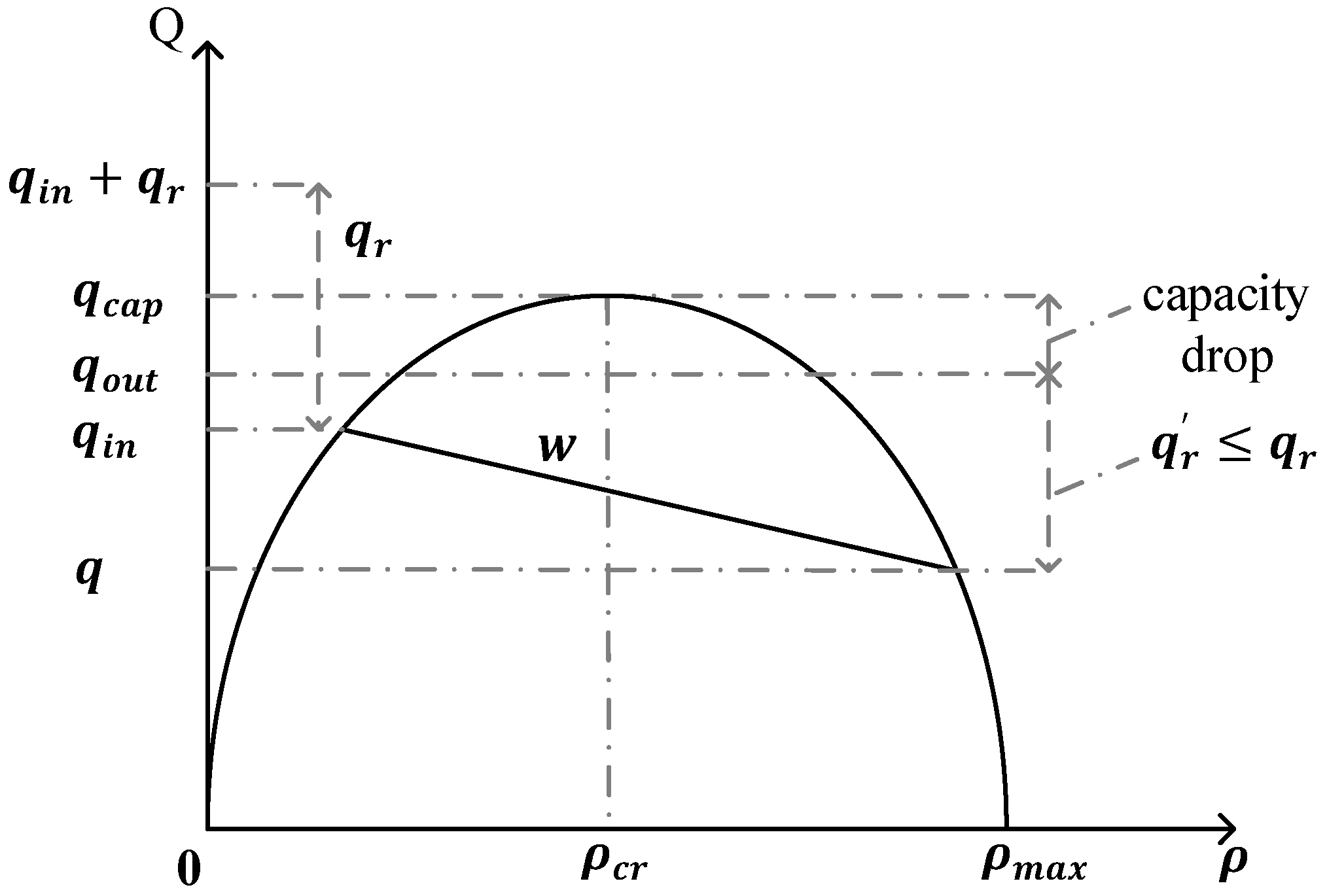
The notion of capacity drop can be illustrated using Figure 1 and Figure 2, with respect to merging congestion at a freeway on-ramp. As shown in Figure 1, when the sum of the upstream demand q i n and on-ramp demand q r exceeds the capacity of the ramp-merging region, congestion sets in. Based on a large number of field observations, it is known that the congestion discharge flow q o u t at the congestion head is often considerably lower than the capacity there. During congestion, the factual on-ramp inflow q r will probably be less than the on-ramp demand q r . With all these in mind, the mainstream flow q under congestion and the resulting congestion shockwave w can be conceptually depicted on the fundamental diagram in Figure 2.
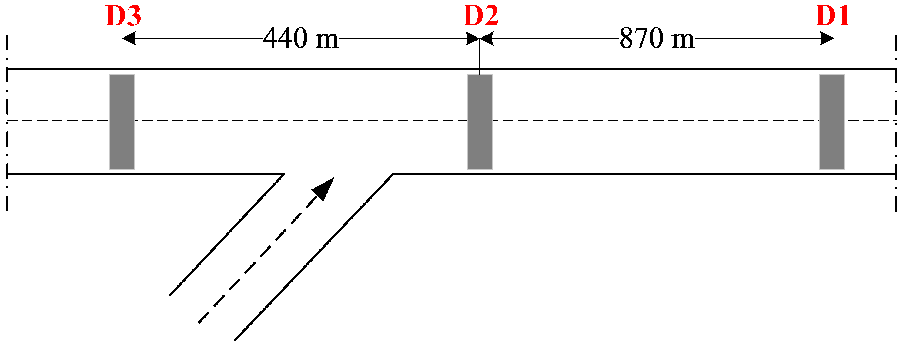
A field-data-based example is given below to further illustrate the notion of capacity drop. Figure 3 displays a ramp-merging section of an inner urban expressway in Shanghai, where D2, D1, and D3 stand for the loop detectors installed, respectively, in the ramp-merging area, downstream, and upstream of the merging area. The flow and density curves over time, as well as the corresponding fundamental diagrams, are displayed in Figure 4 for D1–D3, with each line (of two sub-figures) addressing one specific detector.
As shown in Figure 4a, the traffic flow measured at D2 in Figure 3 peaked around 4200 veh/h at about time point 20, followed by a consistent capacity drop with the discharge flow maintained at about 3700 vhe/h, yielding a capacity drop of about 500 veh/h (11.9%). Figure 4b plots the fundamental diagram with the capacity drop. Following the capacity drop, the flow-density points are scattered around the critical density and adjacent area on the right. Figure 4c,d displays traffic at D1 in Figure 3. The flow rate was very close to that at D1, which is natural due to flow conservation, but the density was slightly lower than that at D2. As a result, the flow-density points in the fundamental diagram (Figure 4d) are congregated to the left of the critical density region.
Figure 4e,f shows the traffic at D3 in Figure 3. Due to the shockwave propagation, the “drop” in flow was much greater than D1, and it was accompanied by a rapid increase in density. In the fundamental diagram (Figure 4f), accordingly, more flow-density points are scattered to the far right of the critical density, sustaining a much lower flow than the capacity.

1.2. The Significance of Capacity Drop

Capacity drop reflects infrastructure performance degradation and leads to increased traffic congestion and longer vehicle delays. That the capacity of a road network may drop substantially when it is most needed during a peak period has been a baffling feature of human-driven traffic dynamics and a main concern for traffic operators [15]. Capacity drop is not only important for traffic flow theory and modeling, but also significant in traffic control. As a matter of fact, the significance and effectiveness of ramp metering and mainstream traffic flow control are very much justified by the presence of capacity drop in field. This understanding of the role of capacity drop in freeway traffic control was shared by a few other researchers [9,16,17,18,19], and carefully studied and demonstrated by Wang et al. [1]. Therefore, traffic control measures, if appropriately designed, should prevent or delay the occurrence of capacity drop, and traffic simulation models used to design and evaluate traffic control measures should be capable of replicating capacity drop.

1.3. The State of the Art and Contributions of This Work

The mechanism of capacity drop has not yet been well understood in terms of traffic flow theory, and most macroscopic traffic flow models so far developed either do not account for capacity drop adequately, or are not able to emulate it sufficiently against field observations, see a recent review by Kontorinaki et al. [19]. Specifically, no analytical macroscopic traffic flow model is available, whereby the level of capacity drop could be directly influenced (e.g., via calibration of some parameters) to match traffic data, though some higher-order models such as METANET can create a capacity drop to some extent [20]. The works of generating capacity drop in microscopic simulation are even less. A number of commercial tools for microscopic traffic simulation, e.g., AIMSUN, VISSIM, have been widely used; surprisingly, it is not yet easy to faithfully reproduce capacity drop at bottlenecks, e.g., freeway merges and lane drops, in microscopic simulation [16,21,22,23].
This paper serves as a tutorial report that intends to shed some light on techniques of reproducing capacity drop at freeway ramp merges in macroscopic and microscopic traffic simulation. First, a comprehensive literature review is presented in Section 2 on capacity drop from the perspectives of behavioral mechanism, macroscopic, and microscopic traffic modeling. Second, the subject is studied using the macroscopic traffic flow model METANET with respect to ramp merging scenarios with and without ramp metering. Third, a major weakness of commercial microscopic traffic simulation tools in creating capacity drop at ramp merges lies in the lane-changing models used, and a forced lane changing model for ramp-merging vehicles is developed and incorporated into the commercial traffic simulation tool AIMSUN. The AIMSUN tool, extended and carefully calibrated against real data, is then examined for its capability to reproduce capacity drop in a complicated traffic scenario with merging bottlenecks.
The simulation results obtained in this paper demonstrate that adequate capacity drop can be delivered for bottlenecks using both macroscopic and microscopic simulation tools. Capacity drop is essentially a macroscopic traffic flow phenomenon with some internal and complicated mechanisms at the microscopic level. This paper conducts comparable studies to replicate capacity drop at freeway ramp merges from both perspectives, which can be insightful and helpful in understanding capacity drop. To the best of our knowledge, similar efforts were scarcely reported before. The remaining part of the paper is organized as follows. Section 2 presents the overview. Section 3 and Section 4 focus on the reproduction of capacity drop using METANET and extended AIMSUN, respectively. Section 5 concludes the paper.

2. Literature Review

2.1. Behavioral Mechanisms for Capacity Drop

2.1.1. Longitudinal Factors

A comprehensive understanding of the causes of the capacity drop remains insufficient. It has been found that capacity drop is highly relevant to longitudinal and lateral behaviors of vehicles. From the longitudinal perspective, there are four potential factors that contribute to the capacity drop.
(1)
Hysteresis
Firstly, some studies [24,25,26] have associated capacity drop with traffic flow hysteresis [27,28] in the macroscopic traffic sense. Hysteresis is manifested as two distinct branches in the speed-density or flow-density fundamental diagram, corresponding to traffic flow in the deceleration and acceleration processes, respectively. Before traffic breakdown occurs at a bottleneck, traffic flow gets denser with the mean speed gradually decreasing, leading to the capacity flow for a short time period. After the breakdown, the traffic flow out of the bottleneck accelerates with a lower density than when it was decelerating, thus presenting a lower outflow. Secondly, the deceleration and acceleration processes may also be checked from a microscopic view, in which the two processes are again asymmetric, showing a ring shape in the speed-spacing coordinate. More specifically, the spacing between vehicles is greater when traffic flow is accelerating than when decelerating. Some studies have directly attributed capacity drop to the asymmetry between the acceleration and deceleration processes [29,30,31].
Another explanation, again relevant to the mean spacing of vehicles and also supported by empirical data [32,33], is that drivers tend to maintain smaller headways under free-flow conditions, but prefer larger headways during congestion. Therefore, the maximum flow of traffic under free flow is greater than when traffic is recovered from congestion, thus exhibiting capacity drop. This was also confirmed with numerical simulations [24,33,34].
(2)
Difference in vehicular acceleration
Focus on a number of vehicles consecutively exiting from the congestion head at a bottleneck; it is often the case that a leading vehicle accelerates at a higher acceleration, but the following vehicle reacts at a lower one, thus yielding a void between the two vehicles. Normally, voids in a lane could be filled by vehicles from the neighboring lanes. However, in the current case, the voids could hardly be filled for the two reasons: (1) vehicles rarely change lanes in the process of acceleration, and (2) large voids tend to appear in the low-speed lane and will not typically be the targets for lane changes. Due to such lasting voids in all lanes, a flow drop occurs, leading to capacity drop at the head of the congestion [35].
(3)
Drivers’ relaxation after a ramp merge
As observed from real data, congestion at a ramp merge usually appears a few hundred meters downstream from the ramp nose, which is, in most cases, downstream of the acceleration lane drop [36,37]. This is probably due to the fact that both merging drivers and drivers in the mainstream are very attentive over the range of the acceleration lane, thus tolerating relatively short intervehicle gaps at high speeds (which corresponds to relatively high flows). After the acceleration lane drop, however, drivers relax and attempt to restore their usual gaps, a traffic breakdown then occurs. This, along with the second point above, may provide an explanation to the occurrence of CD. In the literature, this is also referred to as the “boomerang effect” [38] or capacity funnel [39,40].
(4)
Distracted drivers
When drivers are distracted from their driving tasks, they may become less motivated to follow each other closely, thus leading to capacity drop [41]. Quite often drivers are more interested in using their attentions for rubbernecking rather than efficient following. Rubbernecking refers to the activity of drivers who slow down to see something happening on the other side of a road or highway. Based on the analysis of NGSIM data, some congestion was generated by rubbernecking, because drivers’ reaction patterns change while passing through the rubbernecking area. As a result, the discharge flow of the rubbernecking zone is significantly reduced as vehicles enter it with decreased speeds [26]. In addition, driving in prolonged congestion is another possible reason for capacity loss, whereby capacity drop can be significantly exacerbated.

2.1.2. Lateral Factors

From the lateral perspective of vehicular motions, typically lane changes, two explanations have been proposed for capacity drop. The first one attributes the occurrence of capacity drop to the perception inaccuracy of lane-changing vehicles which act at speeds lower than the mean speed in the target lane. This leads to the “rabbits and slugs” effect [25], where a group of vehicles with lower free-flow speeds (slugs) change lanes, impeding the movement of vehicles with higher free-flow speeds (rabbits) on the target lane, thus leading to a reduction in the downstream flow of the target lane. A typical example of such is lane changes by ramp-merging vehicles.
In association with the first explanation, the second one is concerned with bounded accelerations of lane-changing vehicles. Specifically, it takes some time for lane-changing vehicles to accelerate up to the mean speed in the target lane and hence voids are created in front of the lane-changing vehicles (see also the second factor in Section 2.1.1). As a result, some lane-changing vehicles behave on the target lane like moving bottlenecks with temporal flow restrictions and locally reduced capacity [13,42,43,44,45]. The same issue may also be checked from a slightly different angle. When a vehicle changes lanes, it temporarily occupies two lanes at the same time and thus consumes more than a single vehicle worth of capacity [46,47]. Some researchers also tried to combine the two viewpoints [48].

2.2. Capacity Drops in Macroscopic Traffic Simulations

2.2.1. First-Order Models

As seen from Section 2.1, nearly all studies of capacity drop are still at the level of phenomenon explanation, and the internal mechanism of capacity drop has not been understood so well that macroscopic traffic flow models can be based to formulate capacity drop analytically. Nevertheless, efforts have been made to create capacity drop with macroscopic models [19]. Specifically, a number of extensions or modifications to the LWR model [49,50] have been proposed to introduce capacity drop exogenously in four approaches.
The first approach is to explicitly incorporate capacity drop into the fundamental diagram of LWR, with two flow values around the critical density [2,5,14,51,52,53]. Similar modifications have also been made on the cell transmission model (CTM), a popular time-space-discretized version of LWR with a triangular or trapezoidal fundamental diagram proposed by Daganzo [54]. According to CTM, a demand function and a supply function are both defined for a cell, and the flow out of the cell is determined by the minimum of the two functions. In order to introduce capacity drop to CTM, manipulations can be made on the demand or supply function. For instance, Muralidharan and Horowitz [55,56] and Li et al. [55] created capacity drop by modifying the demand function for the bottleneck cell when the density of the upstream cell becomes overcritical. Jin et al. [57] modified the supply function by setting an exogenously specified reduced capacity, which is activated when the upstream demand is greater than the downstream supply and there is an upstream queue. An alternative way is reported by Han et al. [58,59]. This first approach may lead to infinitely large wave velocities around the critical density [60].
The second approach to creating capacity drop focuses on the introduction of the bounded acceleration to LWR [61,62,63,64,65]. LWR is based on the static fundamental diagram to determine speeds from densities. This means any change in the density of traffic flow leads to a mean speed change instantaneously, which entails unbounded acceleration/deceleration [66]. Additionally, the incapability of LWR to create capacity drop is closely related to this unbounded acceleration/deceleration.
The third approach attempts to reproduce capacity drop from the perspective of hysteresis already described in Section 2.1. The standard CTM is not capable of generating the hysteresis effect. Alvarez-Icaza and Islas [67] and Yuan et al. [31] both developed hysteresis CTM (HCTM) by constructing two congestion branches in its employed flow-density fundamental diagram, with the upper one corresponding to the speed-decreasing phase and lower one the speed-increasing phase, directly emulating what is commonly observed in field data for hysteresis. In addition, the capacity drop phenomena were reported with these models.
The fourth approach tries to reproduce capacity drop using traffic flow models that reflect vehicle heterogeneity. Traffic flow is composed of different types of vehicles, typically passenger cars and trucks. Vehicle heterogeneity significantly affects traffic flow characteristics, such as capacity drop. In congestion, vehicles all move slowly at essentially the same speed, leaving no room for overtaking or lane changing. However, when recovering from congestion, larger vehicles, e.g., trucks and buses or vehicles with a slower speed preference, start slower than smaller cars and thus stay longer in congestion. As a result, a lower flow than capacity occurs at the downstream of bottlenecks. A number of multiclass traffic flow models have been developed to address heterogeneity and capacity drop, most of which are based on the LWR model [68,69,70,71,72].

2.2.2. Higher-Order Models

The capability of the higher-order traffic flow models to replicate capacity drop has only been studied in a couple of works. For instance, Mohammadian et al. [73] calibrated and examined a number of higher-order models to this end using field data. The considered models included METANET [74,75], GSOM [76], Jiang’s model [77], and GKT [78]. METANET and GKT were found to be capable of replicating capacity drop. Tampère et al. [41] proposed a higher order “human-kinetic” traffic flow model with driver activation level dynamics, leading to variable car following styles with the same driver depending on traffic conditions. This affects, among other things, the level of capacity drop exhibited by the human-kinetic model [41]. As previously mentioned, LWR includes a static speed-density relation, implying unbounded acceleration/deceleration and hence delivering no capacity drop. On the other hand, METANET includes a dynamic speed-density equation, by which the acceleration is no longer infinite, and yields capacity drop to an extent. The reader is referred to Wang et al. [20] for a recent discussion on generating capacity drop using the higher-order traffic flow models. In Section 3, METANET is employed to reproduce capacity drop for a freeway ramp merge case.

2.3. Capacity Drops in Microscopic Traffic Simulations

The studies in Section 2.1 have shown that capacity drop is highly relevant to longitudinal and lateral behaviors of vehicles. For reproducing capacity drop via microscopic simulations, most studies have been conducted from the longitudinal (car-following) perspective, and fewer from the lateral (lane-changing) perspective.

2.3.1. Longitudinal Perspective

In Zhang and Kim [34], the driver response time is modeled as a function of vehicle spacing and traffic phases (acceleration, deceleration, or free-flow), and a car-following model with a variable driver response time is constructed, which was found to generate hysteresis. The model was tested numerically in a single-lane loop scenario and exhibited a capacity drop. Treiber et al. [33] studied in a single-lane loop scenario how vehicle headways varied with the velocity variance with the impact on capacity drop. Chamberlayne et al. [79] conducted simulations in ramp merging scenarios using traffic simulation package INTEGRATION, where the vehicle heterogeneity, or more precisely the truck ratio, was considered to be the main factor in triggering capacity drop, because of the difference in the acceleration of cars and trucks. Monamy et al. [80] replicated the capacity drop in ramp-merging scenario with a single-lane mainline. They integrated the driver’s different spacing preferences by introducing a term related to the headway in the optimal velocity function, and generated capacity drop.

2.3.2. Lateral Perspective

Chen and Ahn [43] created capacity drop in a ramp merging scenario, by ordering on-ramp vehicles to change lanes at speeds lower than the mean speed in the mainstream, and by commanding them to accelerate at a fixed acceleration after their lane changes so as to create voids in front of them, thus leading to capacity drop. Souza et al., [81] replaced at ramp merges in AIMSUN the default Gipps lane-changing model with Hidas’ lane-changing model [82] and generated capacity drop after careful model calibration.
The internal mechanism of capacity drop is not yet fully clear. As a result, no analytical macroscopic traffic flow model is available, whereby the level of capacity drop could be directly influenced to match field traffic data. The case of microscopic traffic simulation models is even more complex. As each microscopic model includes a large number of parameters, the correspondence of the parameters and resulting capacity drop is very vague. Existing studies in microscopic simulation, as reviewed above, have tried from various perspectives and in different approaches, but, so far, no systematical framework is available for the reproduction of capacity drop. In Section 4, an effort is made on the basis of commercial software AIMSUN to replicate capacity drop at a freeway ramp merge, where the development of a proper lane-changing model for ramp-merging vehicles is essential.

3. Macroscopic Traffic Flow Modeling with Capacity Drop

3.1. The Second-Order Macroscopic Traffic Flow Model METANET

The METANET model was applied to simulate traffic flow dynamics on freeways. Any link m in METANET represents a freeway stretch and can be divided into a number N m of segments of equal length L m . The key components of METANET for a segment i of link m are the conservation equation, transport equation, mean-speed dynamic equation, and steady speed-density relation:
ρ m , i k + 1 = ρ m , i k + T L m λ m q m , i 1 k q m , i k  
q m , i k = ρ m , i k v m , i k λ m
v m , i k + 1 = v m , i k + T τ V ρ m , i k v m ,   i k + T L m v m , i k v m , i 1 k v m , i k ν T τ L m ρ m , i + 1 k ρ m , i k ρ m , i k + κ δ T L m λ m q μ k v m , 1 k ρ m , i k + κ
V ρ m , i k = v f , m exp 1 α m ρ m , i k ρ c r , m α m
where T denotes the length of discrete time steps, ρ m , i k (veh/km/lane) traffic density in segment i of link m at time step k , q m , i k (veh/h) the number of vehicles leaving segment i over time step k , v m , i k (km/h) the mean speed of vehicles in segment i at time step k . In addition, λ m denotes the number of lanes, v f , m the free speed, ρ c r , m the crucial density, α m a fundamental diagram parameter of link m. τ , κ , and δ are constant model parameters for all links in METANET. The interested reader is referred to [74,83,84,85,86] for more details.

3.2. Simulation Setup

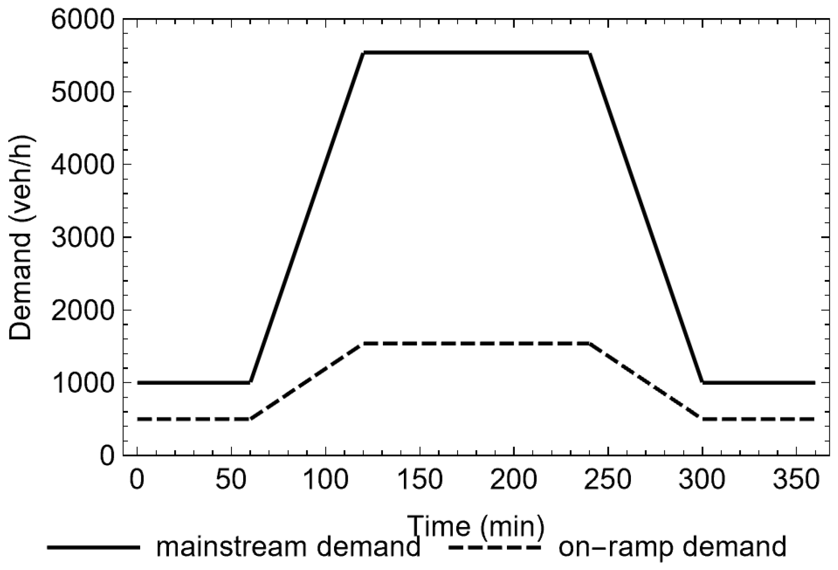
As shown in Figure 5, a three-lane freeway stretch of 4 km with an on-ramp was considered for the simulation study. The whole stretch was divided into 16 segments, with each segment 250 m in length. The merging area was located in segment 9. A detector was placed at the downstream boundary of segment 9, where the capacity drop occurs when the merging area is overloaded. To emulate the merging congestion and reproduce the capacity drop, the used METANET parameters are presented in Table 1. The interested reader is also referred to [19,73] for more details of creating capacity drop using METANET. In addition, the considered demand scenario is plotted in Figure 6.
The objectives of the macroscopic simulation evaluation in Section 3 are two-fold: (1) to show the feasibility of creating capacity drop at an overloaded ramp-merging bottleneck using the macroscopic simulation tool METANET, and (2) to display how to prevent the ramp-merging congestion and maintain the capacity flow with ramp metering in the same simulation scenario in turn to demonstrate the credibility of created capacity drop in (1). The feedback local ramp metering algorithm ALINEA [87] is applied to this end.

3.3. Simulation Results

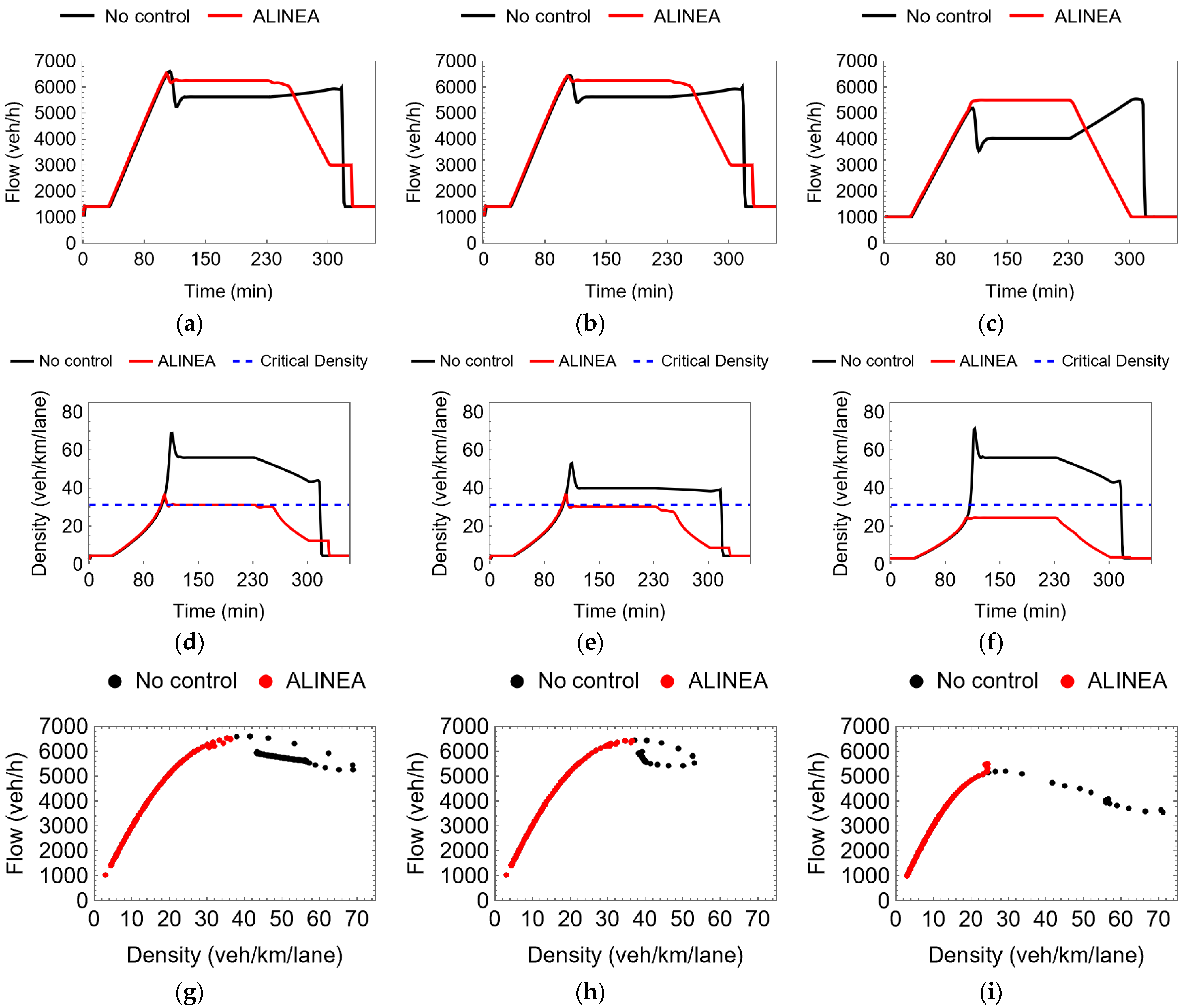
Note in this simulation example that segments 9, 10, and 8 represents the bottleneck, the immediately downstream and upstream of the bottleneck. Figure 7 presents the flows, densities, and the fundamental diagrams of these three segments. The “no control” case is considered first, with the results marked in black in Figure 7. The results were rather comparable to Figure 4, in terms of the stretch layout, the choice of the three comparative locations, and the corresponding traffic flow dynamics concerning capacity drop. More specifically, as shown in Figure 7a, the flow of segment 9 reached the capacity around 6500 veh/h, at about 100th minute from the simulation start, following which the capacity drop took place, with the segment flow staying below the capacity and the segment density (Figure 7d) higher than the critical density that was around 31 veh/km/lane. The flow drop at the same level of the capacity drop is observed in segment 10 (Figure 7b), with the density staying around the critical density (Figure 7e). On the other hand, segment 8 (Figure 7c,f) was heavily congested due to the amplifying effect of the on-ramp inflow on the shockwave propagation. Figure 7g–i present the associated fundamental diagrams. Overall, the capacity drop at the ramp merging bottleneck was reproduced in macroscopic simulation and was quite consistent with what is observed with real data in Figure 4.
To further investigate the reproduction of the capacity drop at this ramp-merging bottleneck in macroscopic simulation, the feedback ramp metering algorithm ALINEA [87] was applied, with the corresponding results presented in Figure 7 in red. Clearly, the merging congestion in the no control case was prevented and the capacity drop was avoided. The density of the bottleneck (segment 9 in Figure 7d) and of its right downstream (segment 10 in Figure 7e) were kept at the critical density, and the sustainable flow throughputs of the two segments were maximized at the capacity flow level during the peak period (Figure 7a,b). On the other hand, segment 8 was under critical (Figure 7f,c) and the mainstream arrival flow (Figure 6) was fully served.

4. Microscopic Traffic Modeling with Capacity Drop

4.1. Enhanced Microscopic Traffic Simulator AIMSUN

This section addresses the reproduction of capacity drop at a ramp-merging bottleneck on a microscopic simulation platform built with the extended AIMSUN. The car-following and lane-changing models are fundamental for any microscopic traffic simulation tool to emulate behaviors of individual vehicles, and therefore essential to replicate complex traffic flow patterns like merging congestion and capacity drop. The default car-following model employed by AIMSUN is the Gipps model [88]. Over the years many studies have been conducted regarding the deficiencies of the Gipps car-following model. For example, Wang et al. [89,90] commented that the Gipps model was unable to reproduce traffic breakdown and hysteresis. Treiber et al. [91] also found Gipps with weaknesses in representing traffic flow instability and hysteresis effects, while these features are thought closely related to capacity drop, see also the literature review in Section 2.1. In addition, Ciuffo et al. [92] delivered a comprehensive review of the Gipps-type of car-following models and pointed out that the Gipps models include some coefficients that are hard to interpret for their physical meaning.
On the other hand, the Intelligent Driver Model (IDM) of car following [91] has become increasingly more popular in the past decade. IDM has a better capability to reproduce traffic breakdown [93] and hysteresis [94,95]. Additionally, the model can better reflect traffic flow instability when traffic flow is disturbed [91]. Each parameter of IDM describes only one aspect of the driving behavior and can be measured empirically. IDM is easier for calibration [96,97]. In this work, we have replaced in AIMSUN the Gipps car-following model with IDM.
In the lane-changing dimension, it is a common problem for commercial software tools of microscopic traffic simulation to satisfactorily create ramp merging congestion (and hence capacity drop). According to our observations with the default AIMSUN, a ramp merging process during a peak period is hard to simulate because ramp merging vehicles usually have to wait on the acceleration lane much longer than in reality, while the mainstream traffic is not much congested. As a typical result, it is not easy to create ramp-merging congestion while over-long ramp queues are built up [21]. One essential reason behind is that the lane-changing model employed by AIMSUN for ramp merging do not perform realistically well.
The AIMSUN’s built-in lane-changing model is the Gipps model [98] that handles any lane change according to the gap acceptance principle. In the ramp merging case, a merging vehicle evaluates gaps that appear in the mainstream lane next to the acceleration lane and selects one for its lane change that will not cause a collision; otherwise, it waits for the next. Such gap acceptance processes simulated are quite conservative against genuine ramp merging processes, which may cause less disturbance to the mainstream traffic but accordingly low merging success rates. In fact, ramp merging processes in reality tend to follow a forced merging mechanism [84,99], that is, as ramp vehicles get closer to the end of the acceleration lane, their desires to change lanes become stronger and they are more likely to accept more demanding gap conditions. In this work, we have replaced in AIMSUN the Gipps lane-changing model with a heuristic forced lane-changing model to enhance AIMSUN’s capability of creating ramp merging congestion and hence capacity drop.
The enhanced AIMSUN and default AIMSUN are compared in Table 2. It is noted that lane changes relating to ramp merging are only mandatory ones but not discretionary ones. For this reason, the discretionary lane changing model employed in AIMSUN was kept unchanged. More information of the mandatory and discretionary lane-changing models is found in [100].

4.2. The Heuristic Lane-Changing Model at Ramp Merges

As shown in Figure 8, vehicle A is moving on the acceleration lane looking for opportunities to merge into the freeway mainstream. Vehicles B and C are the leading and following vehicles in the next lane in the mainstream. Denote the speeds of the three vehicles by v A , v B , v C . Set the start location O of the acceleration lane as the reference point, x A , x B , x C refer to the longitudinal positions of vehicles A, B and C, respectively. Vehicle A decides whether to change lane based on the following conditions:
Change   Lane ? Change   lane   v A > T v x A   Δ v = v C v A < T Δ v x A   x A x C > T d x A   x B x A > T d x A No , otherwise
Note that the conditions for lane change in (5) need to be satisfied altogether. This heuristic lane-changing model considers five variables: the speed v A of vehicle A, the speed difference Δ v of vehicles C and A, and x A , x B , x C . The decision thresholds T v x A , T Δ v x A   and   T d x A are piecewise linear functions of x A . More specifically,
T v x = α 1 x + β 1 ,   0 < x < x 1 γ 1 ,     x 1 < x < x m a x  
T Δ v x = α 2 x + β 2 ,   0 < x < x 2 γ 2 ,   x 2 < x < x m a x  
T d x = α 3 x + β 3 ,   0 < x < x 3 γ 3 ,   x 3 < x < x m a x  
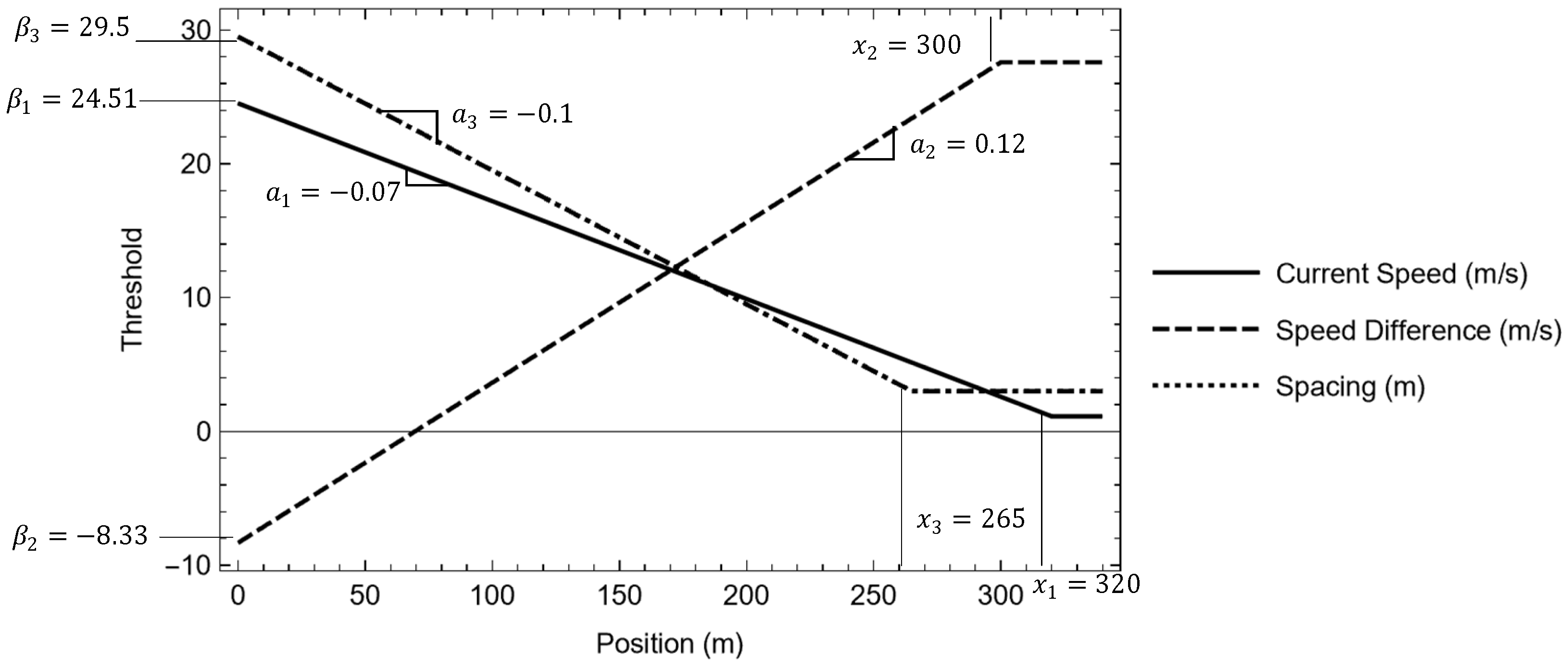
Figure 9 plots T v x A , T Δ v x A   and   T d x A , each with five key parameters, the slope α i , intercept β i , final value γ i , turning point u i ( i = 1 ,   2 ,   3 ), and x m a x .
Generally speaking, when vehicle A runs on the acceleration lane (Figure 8), the driver’s psychological process may be divided into two phases. In the first phase, the driver could be more particular about the moments/conditions at/under which she would accept to merge into the mainstream. In the second phase, however, it becomes more urgent for the vehicle to complete the merging maneuver as it is getting closer to the end of the acceleration lane. As a result, the driver would become less picky about the conditions for merging and tend to conduct a forced lane change. The heuristic lane changing model of (5)–(8) reflects this process of lane-changing decision, where the conditions in (5) are getting more easily satisfied with the thresholds (6)–(8) gradually relaxed as vehicle A moves further downstream on the acceleration lane. In contrast, the threshold criterions used in the default Gipps merging model of AIMSUN does not reflect the variation of lane change behaviors in terms of the lane change urgency, with the threshold criterions remaining the same regardless of the position of the lane-changing vehicle on the acceleration lane and traffic conditions in the mainstream.

4.3. Simulation Setup

The simulation scenario relies on a 9.3 km section of a Dutch freeway A20 between Rotterdam and Gouda. As shown in Figure 10, the section contains two pairs of on/off-ramps, and starts with three lanes and extends for about 3.5 km before becoming two lanes and continues for another 5.8 km.
A simulation platform is established with respect to the stretch using the enhanced AIMSUN and calibrated against real measurement data from the site (Figure 10). The heuristic calibrated lane-changing model Equations (6)–(8) read:
T v x = 0.07 x + 24.51 ,   0 < x < 320 1.12 ,   320 < x
T Δ v x = 0.12 x 8.33 ,   0 < x < 300 27.59 ,   300 < x
T d x = 0.1 x + 29.5 ,   0 < x < 265 3   265 < x
Accordingly, Figure 9 is materialized as Figure 11. More details of the model calibration and validation can be found in Perraki et al. [101,102].
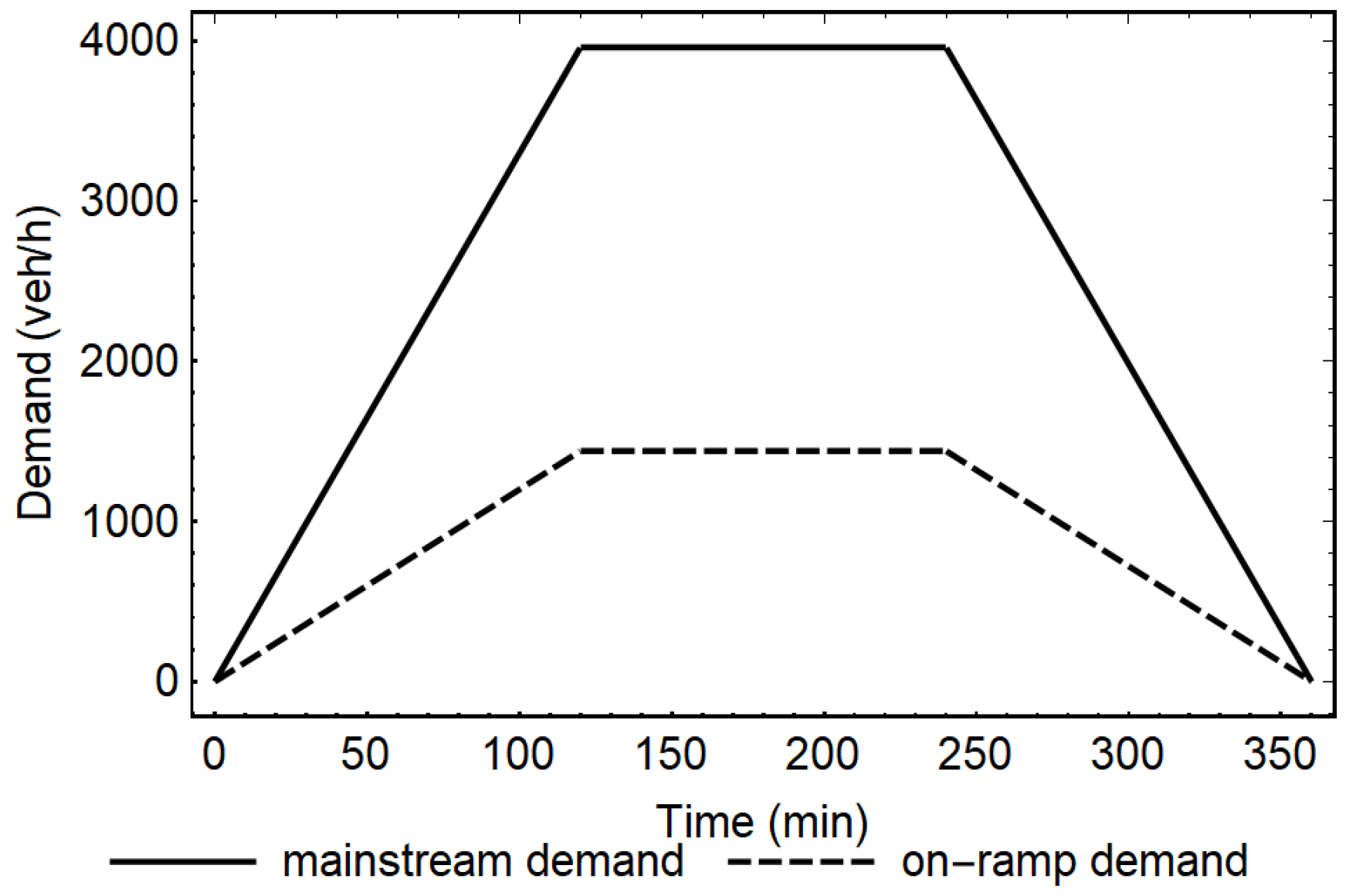
The simulation studies are conducted for the whole stretch in Figure 10, and the considered demands for the mainstream entry and the first on-ramp are displayed in Figure 12. Through extensive simulation tests, the capacity of the first ramp merging area was found to be around 2085 veh/h/lane, and the merging bottleneck is overloaded during the peak period, despite the outflow from the first off-ramp.
The examination and presentation of the study results focus on the section in Figure 13 that includes the merging area of the first on-ramp. To examine the merging congestion, capacity drop, and related traffic flow dynamics, six virtual detectors D1–D6 are placed along the section. D1 is installed 60 m downstream of the end of the acceleration lane and D2 is exactly at the lane drop, while D3–D6 are placed about 120 m apart at the further upstream.

4.4. Simulation Results with Enhanced AIMSUN

4.4.1. Ramp Merging Process Emulation

Firstly, a striking comparison of the ramp merging processes are presented in Figure 14 and Figure 15 based on the default and enhanced AIMSUN, respectively, for the freeway section in Figure 13. Clearly, it is hard for the default AIMSUN to realistically produce a ramp merging process (Figure 14). It took a long time for a ramp vehicle to merge into the mainstream and consequently a lot of merging vehicles were blocked on the acceleration lane and the on-ramp; meanwhile, the mainstream traffic was basically flowing. Consequently, merging congestion (and hence capacity drop) can hardly be expected in such a case. As said previously, this is because of the inefficient Gipps lane-changing model used for ramp merging. By replacing the Gipps model with our heuristic lane-changing model (Table 1), however, the merging results in Figure 15 were delivered, and merging congestion (and hence capacity drop) could be reproduced. More details are presented in the sequel.
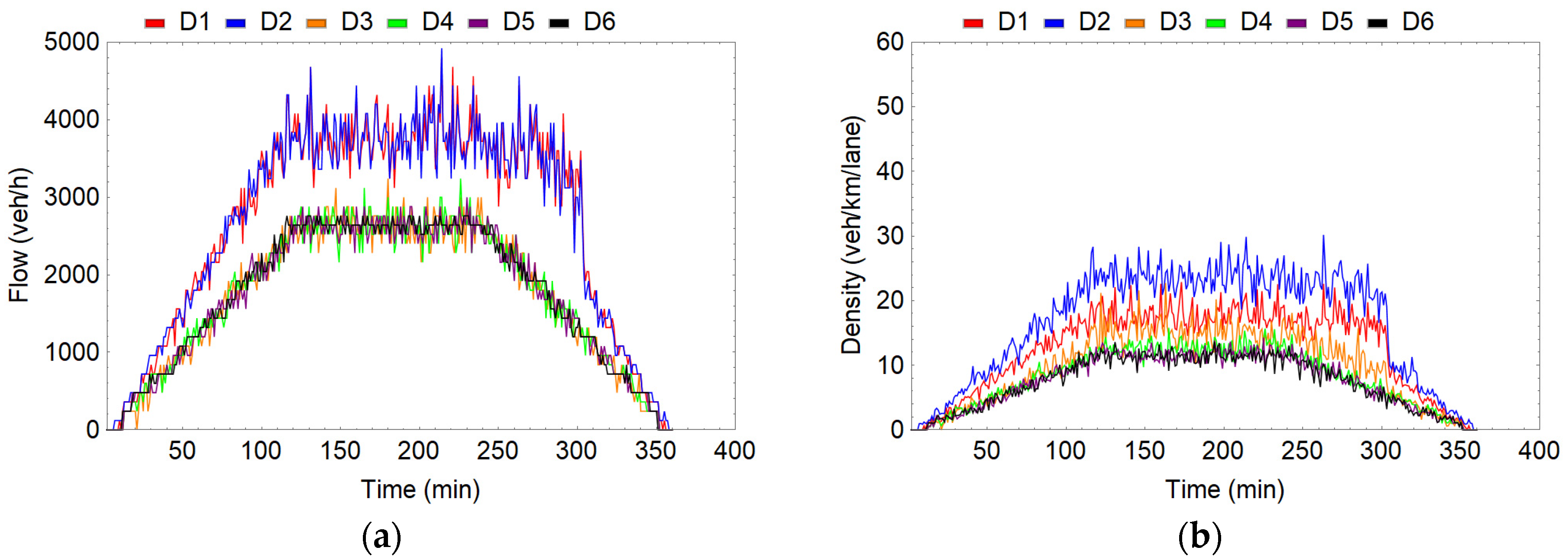
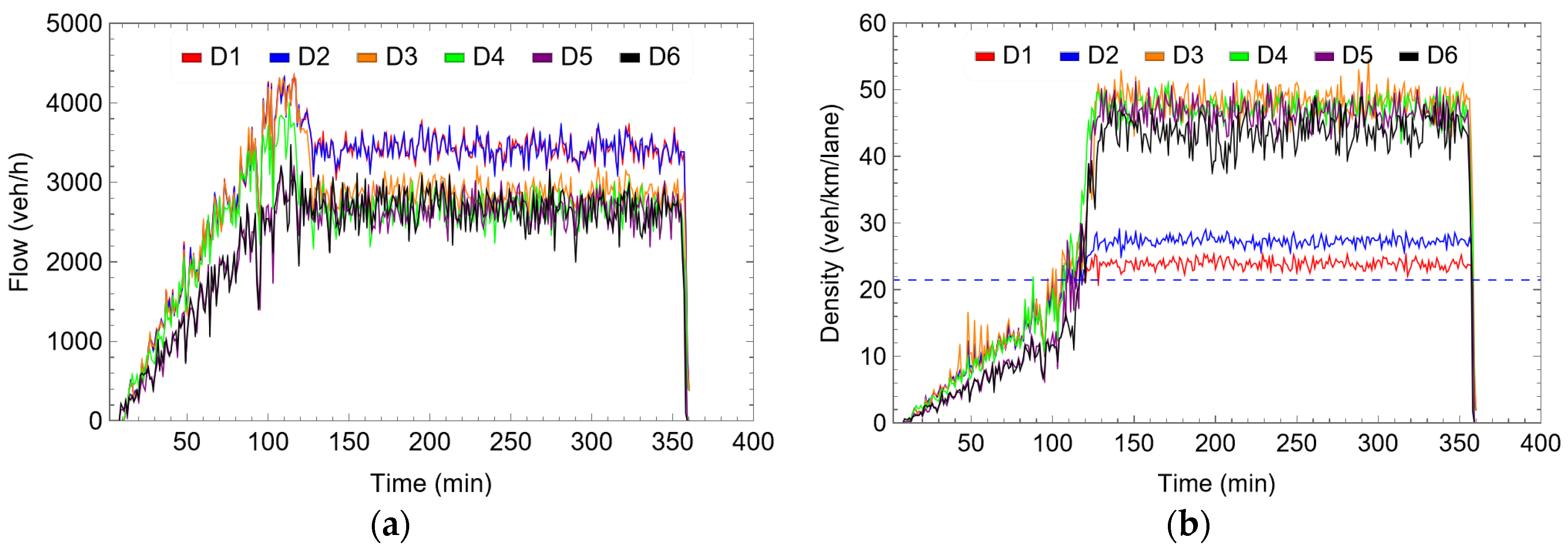
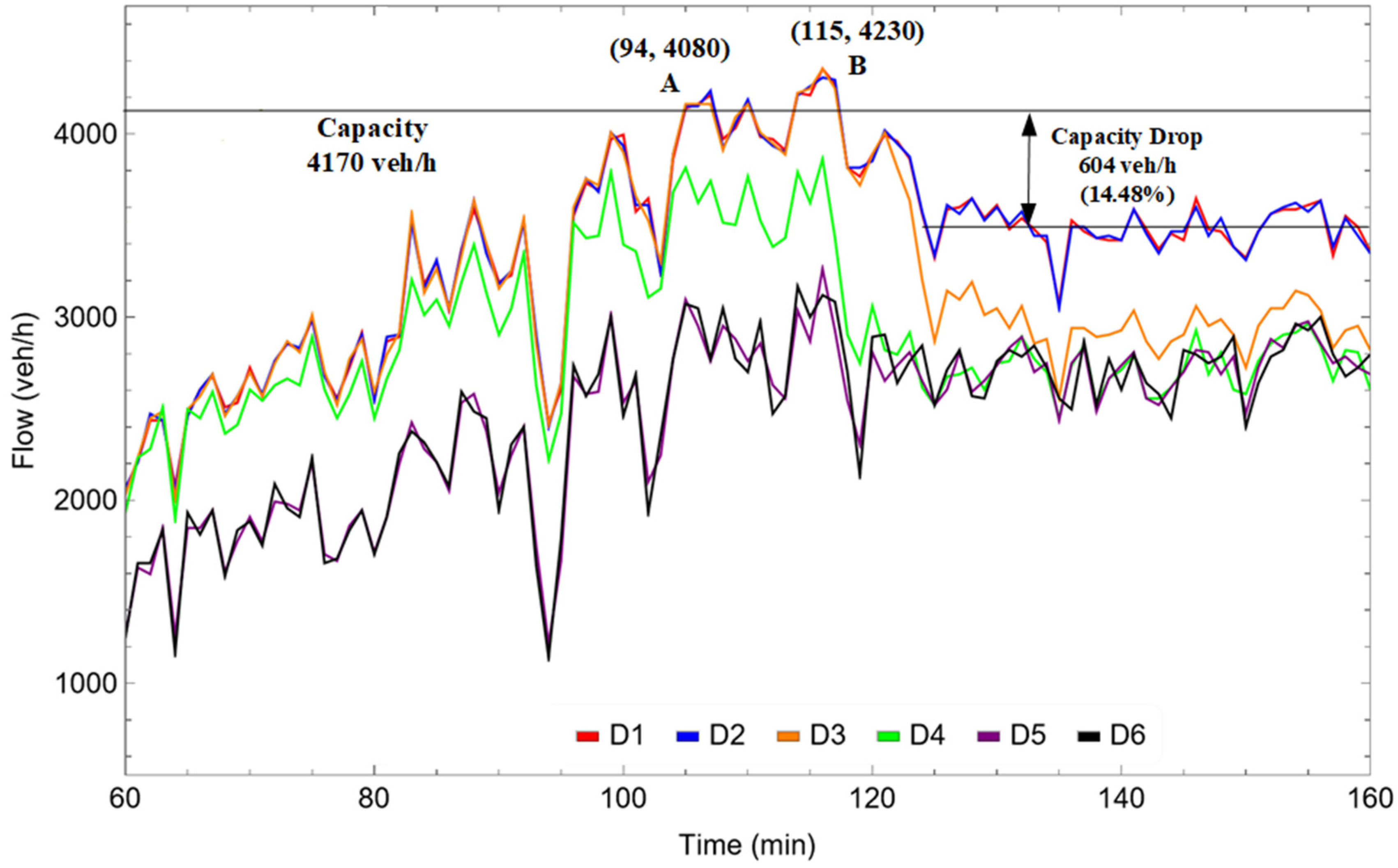
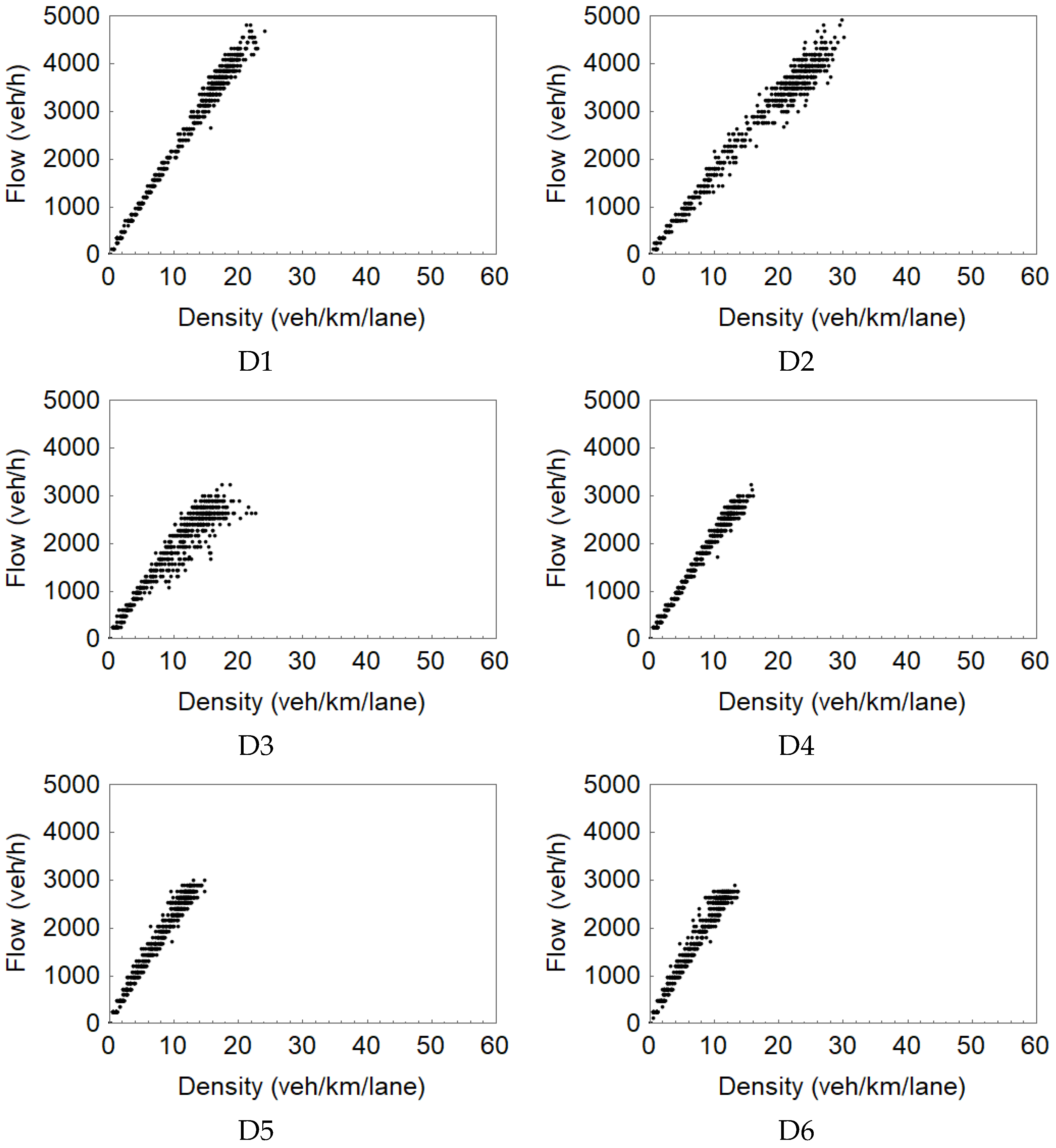
A further investigation into the ramp merging processes revealed that, in the default AIMSUN case, ramp merging happened only around the end of the acceleration lane, particularly between D2 and D3, as shown in Figure 13. As shown in Figure 16, D3–D6 delivered the same flow measurements, while D1 and D2 got the same but higher flow measurements. Clearly, the finding was consistent to what is shown in Figure 14, that ramp merging vehicles had difficulties in merging into the mainstream. In the enhanced AIMSUN case, however, ramp merges took place along the acceleration lane, typically between D2 and D3, D3 and D4, and D4 and D5, see Figure 17a and Figure 18, with the latter zooming in on the former over a period of 100 min. It is seen in Figure 18 that (1) under free-flowing conditions (up to the 65th min in time), the merging/lane-changing maneuvers mostly occurred between D4 and D5; (2) under the capacity flow (between 65th min and 80th min), the merging flow yielded between D3 and D4 and between D4 and D5, and (3) finally after capacity drop (from the 80th min), the merging flow mostly lied between D2 and D3. Overall, when the upcoming demand was lower than the capacity, it is possible for ramp vehicles to merge into the mainstream on the first half of the acceleration lane, with the mainstream flow getting denser, the merging point moved in the direction of traffic towards the middle of the acceleration lane, and when the ramp-merging area was overloaded, merging only took place around the end of the acceleration lane. Such a spatial evolution of merging points is more realistic than the default AIMSUN case where ramp merging always happened at the end of the acceleration lane, regardless of prevailing traffic situations.

4.4.2. Merging Congestion and Capacity Drop Reproduction

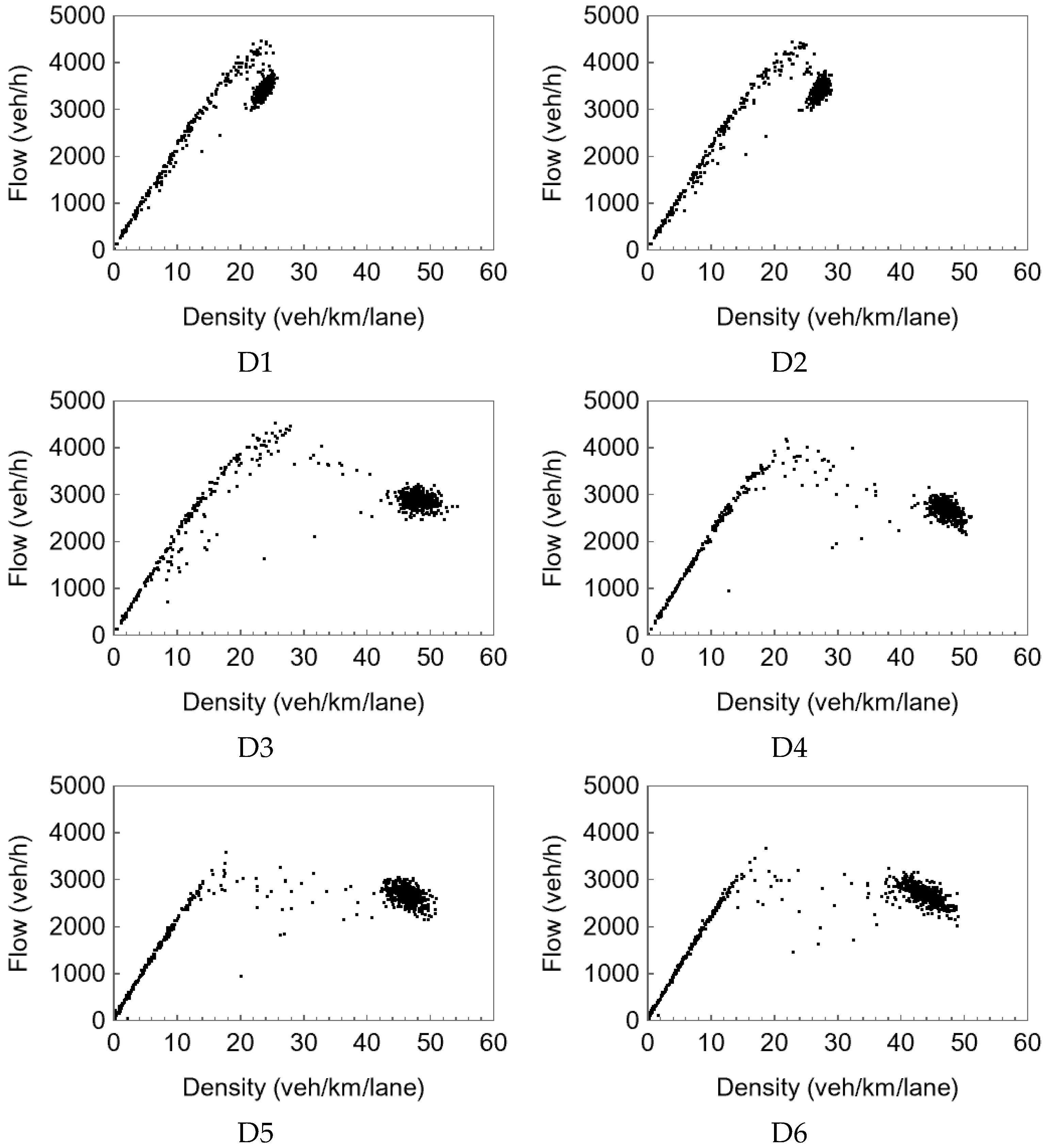
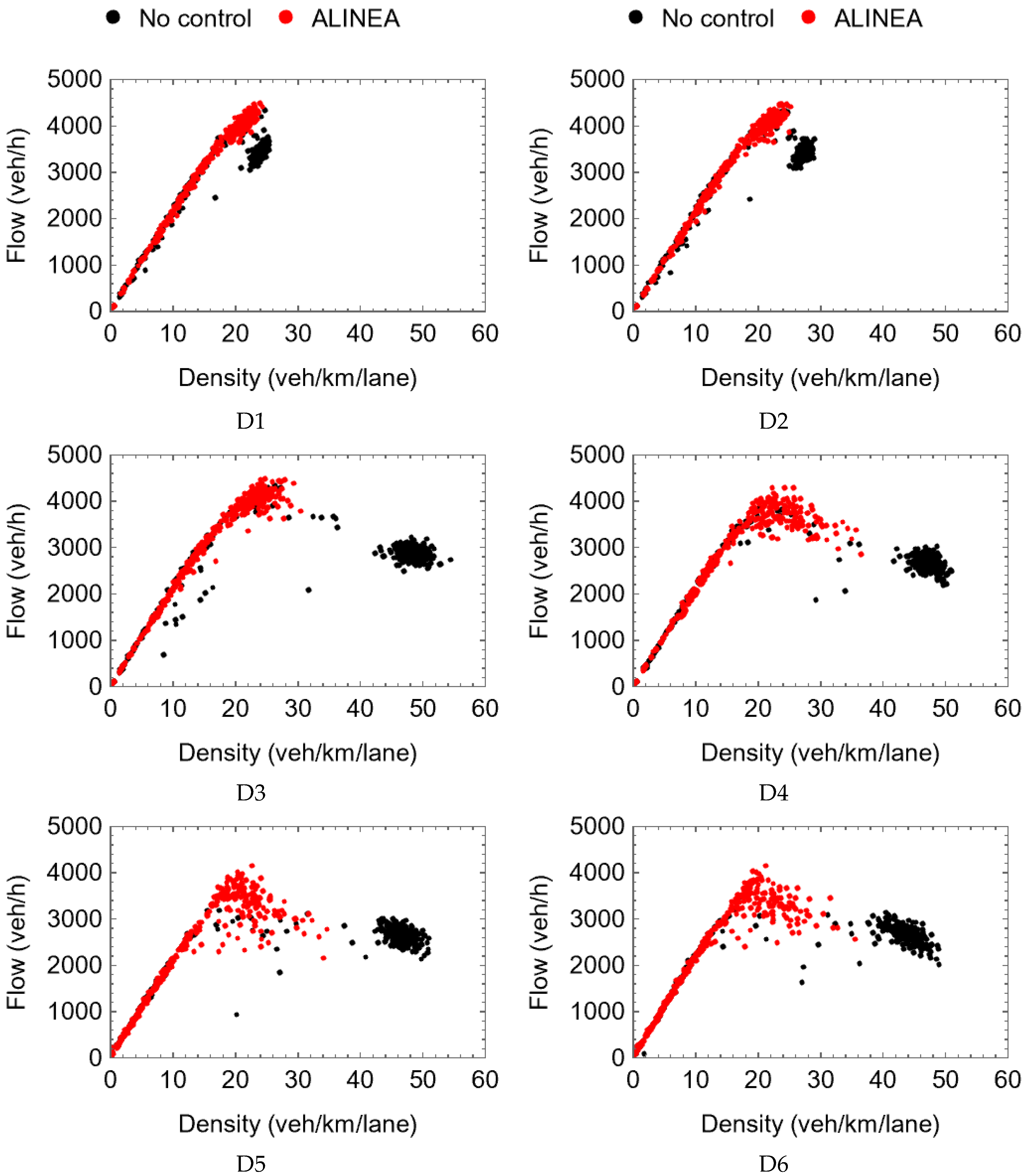
In correspondence to Figure 16 with the default AIMSUN, the resulting fundamental diagrams at D1–D6 in Figure 13 are presented in Figure 19. Evidently, no congestion (and hence no capacity drop) was reproduced for the first ramp-merging bottleneck in Figure 10 and Figure 13 using the default AIMSUN. Based on the enhanced AIMSUN and using the same demand profiles in Figure 12, however, Figure 17 presents the corresponding flow and density trajectories at each detector location, while Figure 20 presents the fundamental diagrams for the six detector locations. As shown, D2 was where capacity drop occurred and possibly merging congestion set in; the location of D1 was never congested because it is at the downstream of the acceleration lane, and the flow drop there was caused by the capacity drop upstream. D3–D6 were affected consecutively by the congestion shockwave from D2. It is seen from the sub-figures of D3–D6 in Figure 20 that the data dots lie on the left-hand side of the critical densities under free-flow conditions and jump to and scattered on the right-hand side.
The critical densities and capacities of D3–D6 are not observed. This is because free-flowing traffic at these locations were dominated by the upstream incoming flows that are definitely below the capacities, while congested traffic conditions there typically resulted from shockwave propagation from the downstream (Figure 20). Therefore, capacity drop could only be seen precisely at activated bottleneck locations with congestion initiated. However, it is quite unlikely in reality that detectors are installed exactly at such locations, and that is why fundamental diagrams with capacity drop like that in Figure 20 (D2) are not often seen with real data. Overall, these simulation results were quite consistent to field observations under similar circumstances; compare also the results of D1–D3 in Figure 17, Figure 18, Figure 19 and Figure 20 with Figure 4.
Figure 18 zooms in on the capacity drop region in Figure 16. Further insight can be gained about the capacity drop. Around 105 min from the simulation start, the incoming demand reached the mainstream capacity which was about 4170 veh/h. The outgoing flow at D2 was kept at the capacity level for about 15 min until it dropped by 14.5%.
Recall that the entire freeway stretch considered is displayed in Figure 10, and, so far, we have concentrated on the merging congestion and capacity drop around the first ramp merge. To possibly present a complete image of traffic status location D2 may experience, one other congestion from the second ramp merge was considered as well. As a result, D2 experienced double congestion from the two merging areas. The resulting fundamental diagram is presented in Figure 21, and its reversing-lambda shape was consistent with some field observations. It should be pointed out that, to create a fundamental diagram of Figure 21, the on-ramp demands needed to be manipulated so that merging congestion first set in at D2 rather than the downstream on-ramp; otherwise, the fundamental diagram at D2 would, understandably, have been very similar to those at D3–D6 in Figure 20. Except for Figure 21, only the results for the partial freeway section in Figure 13 are shown and discussed throughout the paper.

4.4.3. Preventing Capacity Drop with ALINEA

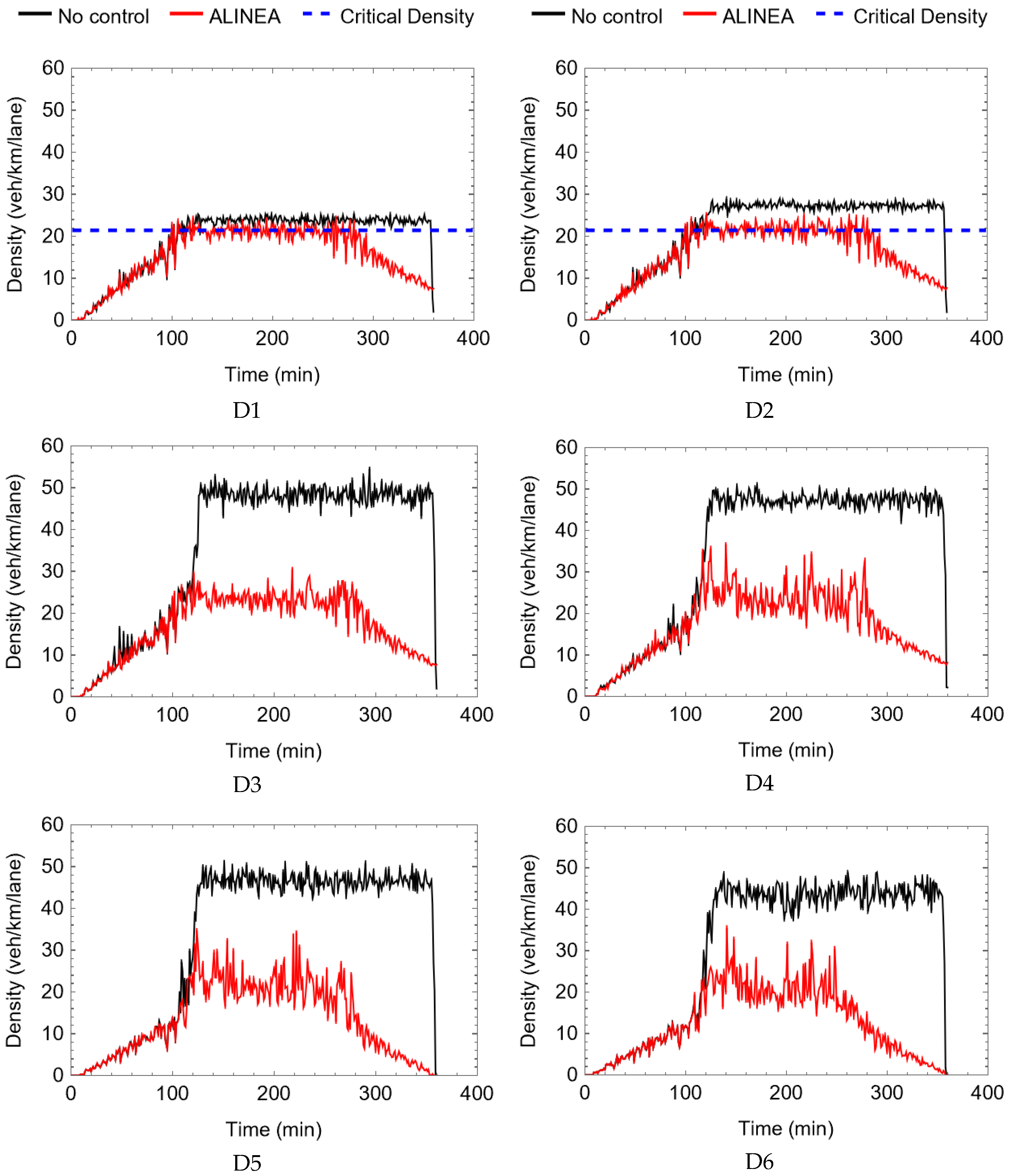
Similar to the macroscopic simulation case in Section 3, ALINEA was also applied to the current microscopic simulation case of the enhanced AIMSUN to demonstrate the merging congestion can be prevented and the capacity flow be maintained. Figure 22 and Figure 23 display flow and density results at each detector in the downstream to upstream order, of which the no-control part is already presented in Figure 17. The associated fundamental diagrams are found in Figure 24, the no-control part of which is already presented in Figure 20. Clearly, without ramp metering, flow measurements at each detector increased with the growth of the demands (Figure 12) until the total demand towards the ramp merging area reached the capacity there. Soon after the merging bottleneck was activated/overloaded, congestion appeared first around D2 with capacity drop, which was also reflected in flow measurements at D1 due to flow conservation. Following the shockwave propagation, flow measurements at D3–5 become even lower, and eventually flow measurements at D6 were lower than the mainstream demand during the peak period. With the local ramp metering algorithm ALINEA applied, however, the congestion was mitigated with capacity flow maintained at D2–5 and the mainstream demand served at D6. Despite the deterministic demands in Figure 12, the resulting flows and densities in Figure 22 and Figure 23 were random, because of the random exiting rate at the first off-ramp as identified with real data from the site in Figure 10, as well as of the stochastic nature of AIMSUN.

4.4.4. Summary

The successful reproduction of capacity drop on this microscopic simulation platform of AIMSUN was attributed to the introduction of the IDM car-following model for all vehicles, the heuristic forced lane-changing model for ramp merging vehicles, and the model calibration based on real data.

5. Conclusions

It is a significant task to understand the mechanism of capacity drop. A traffic model to evaluate traffic control measures needs to be able to reproduce capacity drop in order to deliver reliable evaluation results. This paper conducted comparable studies on capacity drop at freeway ramp merges using macroscopic traffic simulation tool METANET and microscopic traffic simulation tool AIMSUN. Particularly, a heuristic forced lane-changing model was implemented in AIMSUN for ramp-merging vehicles to improve a common deficiency of commercial microscopic traffic simulation tools in creating merging congestion. Both tools were carefully calibrated with field data and then examined for their capabilities of reproducing capacity drop in a complicated traffic scenario with merging bottlenecks. The results obtained with both tools demonstrated that reproducible capacity drop can be delivered with its spatiotemporal pattern consistent to field measurements. This paper intends to shed some light on the reproduction of capacity drop at freeway ramp merges via some thorough macroscopic and microscopic simulation studies, and similar efforts were scarcely reported before.

Author Contributions

Y.W. planned the work, led the research, contributed to the initial draft, and performed the review & editing; L.W. and X.Y. conducted the research, analyzed data, and wrote the initial draft. J.G. participated in the discussion and performed the review & editing. All authors have read and agreed to the published version of the manuscript.

Funding

This work was supported in part by the National Key Research and Development Program of China (project number: 2018YFB1600500), the National Natural Science Foundation of China (project number: 52272315; 52172306), and the Provincial Key R&D Program of Zhejiang (project number: 2021C01012).

Institutional Review Board Statement

Not applicable.

Informed Consent Statement

Not applicable.

Data Availability Statement

The data is included in the text.

Acknowledgments

The authors would like to express many thanks to Markos Papageorgiou, Ioannis Papamichail, Georgia Perraki from Technical University of Crete, Greece, for their significant help with the extended AIMSUN platform built up for the microscopic simulation replication of capacity drop in this work. The authors would also like to thank Bart van Arem from Delft Unviersity of Technology for his support in providing data information related to the Dutch freeway network simulated using the extended AIMSUN in this work.

Conflicts of Interest

The authors declare no conflict of interest.

References

  1. Wang, Y.; Yu, X.; Zhang, S.; Zheng, P.; Guo, J.; Zhang, L.; Hu, S.; Cheng, S.; Wei, H. Freeway Traffic Control in Presence of Capacity Drop. IEEE Trans. Intell. Transport. Syst. 2021, 22, 1497–1516. [Google Scholar] [CrossRef]
  2. Hall, F.L.; Agyemang-Duah, K. Freeway Capacity Drop and the Definition of Capacity. In Freeway Operations, Highway Capacity, and Traffic Flow; National Research Council, Transportation Research Board: Washington, DC, USA, 1991; ISBN 0309051533. [Google Scholar]
  3. Banks, J.H. The Two-capacity Phenomenon: Some Theoretical Issues. In Freeway Operations, Highway Capacity, and Traffic Flow; National Research Council, Transportation Research Board: Washington, DC, USA, 1991; ISBN 0309051533. [Google Scholar]
  4. Edie, L.C. Car-Following and Steady-State Theory for Noncongested Traffic. Oper. Res. 1961, 9, 66–76. [Google Scholar] [CrossRef]
  5. Koshi, M.; Iwasaki, M.; Ohkura, I. Some findings and an overview on vehicular flow characteristics. In Proceedings of the 8th International Symposium on Transportation and Traffic Flow Theory, Toronto, ON, Canada, 1983; pp. 403–426. [Google Scholar]
  6. Drake, J.S.; Schofer, J.L.; May, A.D., Jr. A statistical analysis of speed-density hypotheses. In vehicular traffic science. In Highway Research Record; National Research Council, Highway Research Board: Washington, DC, USA, 1967; pp. 112–117. [Google Scholar]
  7. Payne, H.J. Discontinuity in equilibrium freeway traffic flow. In Transportation Research Board; National Research Council: Washington, DC, USA, 1984. [Google Scholar]
  8. Hall, F.L.; Hurdle, V.F.; Banks, J.H. Synthesis of recent work on the nature of speed-flow and flow-occupancy (or density) relationships on freeways. In Transportation Research Record; National Research Council: Washington, DC, USA, 1992. [Google Scholar]
  9. Chung, K.; Rudjanakanoknad, J.; Cassidy, M.J. Relation between traffic density and capacity drop at three freeway bottlenecks. Transp. Res. Part B Methodol. 2007, 41, 82–95. [Google Scholar] [CrossRef]
  10. Oh, S.; Yeo, H. Estimation of Capacity Drop in Highway Merging Sections. Transp. Res. Rec. 2012, 2286, 111–121. [Google Scholar] [CrossRef]
  11. Yuan, K.; Knoop, V.L.; Leclercq, L.; Hoogendoorn, S.P. Capacity drop: A comparison between stop-and-go wave and standing queue at lane-drop bottleneck. Transp. B Transp. Dyn. 2017, 5, 145–158. [Google Scholar] [CrossRef] [Green Version]
  12. Yuan, K.; Knoop, V.L.; Hoogendoorn, S.P. Capacity Drop: Relationship Between Speed in Congestion and the Queue Discharge Rate. Transp. Res. Rec. 2015, 2491, 72–80. [Google Scholar] [CrossRef]
  13. Leclercq, L.; Laval, J.A.; Chiabaut, N. Capacity drops at merges: An endogenous model. Transp. Res. Part B Methodol. 2011, 45, 1302–1313. [Google Scholar] [CrossRef]
  14. Srivastava, A.; Geroliminis, N. Empirical observations of capacity drop in freeway merges with ramp control and integration in a first-order model. Phys. Rev. E 2013, 30, 161–177. [Google Scholar] [CrossRef] [Green Version]
  15. Papageorgiou, M.; Kotsialos, A. Freeway ramp metering: An overview. IEEE Trans. Intell. Transp. Syst. 2002, 3, 271–281. [Google Scholar] [CrossRef]
  16. Chevallier, E.; Leclercq, L. Do microscopic merging models reproduce the observed priority sharing ratio in congestion? Transp. Res. Part C Emerg. Technol. 2009, 17, 328–336. [Google Scholar] [CrossRef]
  17. Kessels, F. Traffic Flow Modelling: Introduction to Traffic Flow Theory through a Genealogy of Models; EURO Advanced Tutorials on Operational Research; Springer: Berlin, Germany, 2019. [Google Scholar]
  18. Kondyli, A.; Duret, A.; Elefteriadou, L. Evaluation of CORSIM and AIMSUN for Freeway Merging Segments under Breakdown Conditions. In Proceedings of the Transportation Research Board 86th Annual Meeting, Washington, DC, USA, 21–25 January 2007. [Google Scholar]
  19. Kontorinaki, M.; Spiliopoulou, A.; Roncoli, C.; Papageorgiou, M. First-order traffic flow models incorporating capacity drop: Overview and real-data validation. Transp. Res. Part B Methodol. 2017, 106, 52–75. [Google Scholar] [CrossRef]
  20. Wang, Y.; Yu, X.; Guo, J.; Papamichail, I.; Papageorgiou, M.; Zhang, L.; Hu, S.; Li, Y.; Sun, J. Macroscopic traffic flow modelling of large-scale freeway networks with field data verification: State-of-the-art review, benchmarking framework, and case studies using METANET. Transp. Res. Part C Emerg. Technol. 2022, 145, 103904. [Google Scholar] [CrossRef]
  21. Zheng, Z. Recent developments and research needs in modeling lane changing. Transp. Res. Part B Methodol. 2014, 60, 16–32. [Google Scholar] [CrossRef] [Green Version]
  22. Hidas, P. Modelling individual behaviour in microsimulation models. In Proceedings of the Australasian Transport Research Forum (Atrf), 28th, Sydney, NSW, Australia, 1 January 2005. [Google Scholar]
  23. van Beinum, A.; Broekman, E.; Farah, H.; Schakel, W.; Wegman, F.; Hoogendoorn, S. Critical Assessment of Microscopic Simulation Models for Simulating Turbulence around Motorway Ramps. J. Transp. Eng. Part A Syst. 2020, 146, 4019066. [Google Scholar] [CrossRef]
  24. Tampère, C.M. Human-Kinetic Multiclass Traffic Flow Theory and Modelling with Application to Advanced Driver Assistance Systems in Congestion. Ph.D. Thesis, Delft University of Technology, Delft, The Netherlands, 2004. [Google Scholar]
  25. Daganzo, C.F. A behavioral theory of multi-lane traffic flow. Part I: Long homogeneous freeway sections. Transp. Res. Part B Methodol. 2002, 36, 131–158. [Google Scholar] [CrossRef] [Green Version]
  26. Chen, D.; Ahn, S.; Laval, J.; Zheng, Z. On the periodicity of traffic oscillations and capacity drop: The role of driver characteristics. Transp. Res. Part B Methodol. 2014, 59, 117–136. [Google Scholar] [CrossRef] [Green Version]
  27. Treiterer, J.; Myers, J.A. The Hysteresis Phenomenon in Traffic Flow. Transp. Traffic Theory 1974, 6, 13–38. [Google Scholar]
  28. Zhang, H.M. A mathematical theory of traffic hysteresis. Transp. Res. Part B Methodol. 1999, 33, 1–23. [Google Scholar] [CrossRef]
  29. Oh, S.; Yeo, H. Impact of stop-and-go waves and lane changes on discharge rate in recovery flow. Transp. Res. Part B Methodol. 2015, 77, 88–102. [Google Scholar] [CrossRef]
  30. Yeo, H. Asymmetric Microscopic Driving Behavior Theory. Ph.D. Thesis, University of California, Berkeley, CA, USA, 2008. [Google Scholar]
  31. Yuan, K.; Knoop, V.; Schreiter, T.; Hoogendoorn, S.P. A Hybrid Kinematic Wave Model Incorporating Capacity Drops. In Proceedings of the IEEE 18th International Conference on Intelligent Transportation Systems (ITSC), Gran Canaria, Spain, 15–18 September 2015; IEEE: Piscataway, NJ, USA, 2015; pp. 471–476, ISBN 978-1-4673-6596-3. [Google Scholar]
  32. Knospe, W.; Santen, L.; Schadschneider, A.; Schreckenberg, M. Single-vehicle data of highway traffic: Microscopic description of traffic phases. Phys. Rev. E Stat. Nonlinear Soft Matter Phys. 2002, 65, 56133. [Google Scholar] [CrossRef] [Green Version]
  33. Treiber, M.; Kesting, A.; Helbing, D. Understanding widely scattered traffic flows, the capacity drop, and platoons as effects of variance-driven time gaps. Phys. Rev. E Stat. Nonlinear Soft Matter Phys. 2006, 74, 16123. [Google Scholar] [CrossRef] [PubMed]
  34. Zhang, H.M.; Kim, T. A car-following theory for multiphase vehicular traffic flow. Transp. Res. Part B Methodol. 2005, 39, 385–399. [Google Scholar] [CrossRef] [Green Version]
  35. Papageorgiou, M.; Papamichail, I.; Spiliopoulou, A.D.; Lentzakis, A.F. Real-time merging traffic control with applications to toll plaza and work zone management. Transp. Res. Part C Emerg. Technol. 2008, 16, 535–553. [Google Scholar] [CrossRef]
  36. Papageorgiou, M.; Kosmatopoulos, E.; Papamichail, I.; Wang, Y. ALINEA maximises motorway throughput—An answer to flawed criticism. Traffic Eng. Control 2007, 48, 271–276. [Google Scholar]
  37. Papageorgiou, M.; Kosmatopoulos, E.; Papamichail, I.; Wang, Y. A Misapplication of the Local Ramp Metering Strategy ALINEA. IEEE Trans. Intell. Transport. Syst. 2008, 9, 360–365. [Google Scholar] [CrossRef]
  38. Schönhof, M.; Helbing, D. Empirical Features of Congested Traffic States and Their Implications for Traffic Modeling. Transp. Sci. 2007, 41, 135–166. [Google Scholar] [CrossRef] [Green Version]
  39. Buckley, D.J.; Yagar, S. Capacity Funnels Near on-ramps. Transp. Traffic Theory 1974, 6, 105–123. [Google Scholar]
  40. Tampère, C.; Hoogendoorn, S.P.; van Arem, B. Capacity Funnel Explained Using the Human-Kinetic Traffic Flow Model. In Traffic and Granular Flow ’03; Springer: Berlin, Germany, 2005; pp. 189–197. [Google Scholar]
  41. Tampere, C.; Hoogendoorn, S.; van Arem, B. A Behavioural Approach to Instability, Stop and Go Waves, Wide Jams and Capacity Drop. Transp. Traffic Theory 2005, 16, 205–228. [Google Scholar]
  42. Laval, J.A.; Daganzo, C.F. Lane-changing in traffic streams. Transp. Res. Part B Methodol. 2006, 40, 251–264. [Google Scholar] [CrossRef]
  43. Chen, D.; Ahn, S. Capacity-drop at extended bottlenecks: Merge, diverge, and weave. Transp. Res. Part B Methodol. 2018, 108, 1–20. [Google Scholar] [CrossRef]
  44. Duret, A.; Bouffier, J.; Buisson, C. Onset of Congestion from Low-Speed Merging Maneuvers within Free-Flow Traffic Stream. Transp. Res. Rec. 2010, 2188, 96–107. [Google Scholar] [CrossRef]
  45. Leclercq, L.; Knoop, V.L.; Marczak, F.; Hoogendoorn, S.P. Capacity drops at merges: New analytical investigations. Phys. Rev. E 2016, 62, 171–181. [Google Scholar] [CrossRef] [Green Version]
  46. Jin, W.-L. A kinematic wave theory of lane-changing traffic flow. Transp. Res. Part B Methodol. 2010, 44, 1001–1021. [Google Scholar] [CrossRef] [Green Version]
  47. Coifman, B.; Mishalani, R.; Wang, C.; Krishnamurthy, S. Impact of Lane-Change Maneuvers on Congested Freeway Segment Delays. Transp. Res. Rec. 2006, 1965, 152–159. [Google Scholar] [CrossRef]
  48. Jin, W.-L.; Laval, J. Bounded acceleration traffic flow models: A unified approach. Transp. Res. Part B Methodol. 2018, 111, 1–18. [Google Scholar] [CrossRef]
  49. Whitham, G.B.; Lighthill, M.J. On kinematic waves II. A theory of traffic flow on long crowded roads. Proc. R. Soc. Lond. A 1955, 229, 317–345. [Google Scholar] [CrossRef]
  50. Richards, P.I. Shock Waves on the Highway. Oper. Res. 1956, 4, 42–51. [Google Scholar] [CrossRef]
  51. Cassidy, M.J. Bivariate relations in nearly stationary highway traffic. Transp. Res. Part B Methodol. 1998, 32, 49–59. [Google Scholar] [CrossRef]
  52. Lu, Y.; Wong, S.C.; Zhang, M.; Shu, C.-W. The Entropy Solutions for the Lighthill-Whitham-Richards Traffic Flow Model with a Discontinuous Flow-Density Relationship. Transp. Sci. 2009, 43, 511–530. [Google Scholar] [CrossRef]
  53. van der Gun, J.P.; Pel, A.J.; van Arem, B. Extending the Link Transmission Model with non-triangular fundamental diagrams and capacity drops. Transp. Res. Part B Methodol. 2017, 98, 154–178. [Google Scholar] [CrossRef] [Green Version]
  54. Daganzo, C.F. The cell transmission model: A dynamic representation of highway traffic consistent with the hydrodynamic theory. Transp. Res. Part B Methodol. 1994, 28, 269–287. [Google Scholar] [CrossRef]
  55. Li, Z.; Liu, P.; Xu, C.; Wang, W. Optimal Mainline Variable Speed Limit Control to Improve Safety on Large-Scale Freeway Segments. Comput.-Aided Civ. Infrastruct. Eng. 2016, 31, 366–380. [Google Scholar] [CrossRef]
  56. Muralidharan, A.; Horowitz, R. Computationally efficient model predictive control of freeway networks. Transp. Res. Part C Emerg. Technol. 2015, 58, 532–553. [Google Scholar] [CrossRef]
  57. Jin, W.-L. Continuous formulations and analytical properties of the link transmission model. Transp. Res. Part B Methodol. 2015, 74, 88–103. [Google Scholar] [CrossRef]
  58. Han, Y.; Hegyi, A.; Yuan, Y.; Hoogendoorn, S.; Papageorgiou, M.; Roncoli, C. Resolving freeway jam waves by discrete first-order model-based predictive control of variable speed limits. Transp. Res. Part C Emerg. Technol. 2017, 77, 405–420. [Google Scholar] [CrossRef] [Green Version]
  59. Han, Y.; Yuan, Y.; Hegyi, A.; Hoogendoorn, S.P. New Extended Discrete First-Order Model to Reproduce Propagation of Jam Waves. Transp. Res. Rec. 2016, 2560, 108–118. [Google Scholar] [CrossRef] [Green Version]
  60. Jin, W.-L.; Gan, Q.-J.; Lebacque, J.-P. A kinematic wave theory of capacity drop. Transp. Res. Part B Methodol. 2015, 81, 316–329. [Google Scholar] [CrossRef] [Green Version]
  61. Lebacque, J.P. Two-Phase Bounded-Acceleration Traffic Flow Model: Analytical Solutions and Applications. Transp. Res. Rec. 2003, 1852, 220–230. [Google Scholar] [CrossRef]
  62. Monamy, T.; Haj-Salem, H.; Lebacque, J.-P. A Macroscopic Node Model Related to Capacity Drop. Procedia Soc. Behav. Sci. 2012, 54, 1388–1396. [Google Scholar] [CrossRef] [Green Version]
  63. Khoshyaran, M.M.; Lebacque, J.P. Capacity drop and traffic hysteresis as a consequence of bounded acceleration. IFAC PapersOnLine 2015, 48, 766–771. [Google Scholar] [CrossRef]
  64. Roncoli, C.; Papageorgiou, M.; Papamichail, I. Traffic flow optimisation in presence of vehicle automation and communication systems—Part I: A first-order multi-lane model for motorway traffic. Phys. Rev. E 2015, 57, 241–259. [Google Scholar] [CrossRef]
  65. Calvert, S.C.; Snelder, M.; Taale, H.; Van Wageningen-Kessels, F.L.M.; Hoogendoorn, S.P. Bounded Acceleration Capacity Drop in a Lagrangian Formulation of the Kinematic Wave Model with Vehicle Characteristics and Unconstrained Overtaking. In Proceedings of the 2012 15th International IEEE Conference on Intelligent Transportation Systems, Anchorage, AK, USA, 16–19 September 2012; pp. 1371–1376, ISBN 2153-0017. [Google Scholar]
  66. Papageorgiou, M. Some remarks on macroscopic traffic flow modelling. Transp. Res. Part A Policy Pract. 1998, 32, 323–329. [Google Scholar] [CrossRef]
  67. Alvarez-Icaza, L.; Islas, G.J. Hysteretic Cell Transmission Model. In Proceedings of the IEEE 16th International Conference on Intelligent Transportation Systems (ITSC), The Hague, The Netherlands, 1 October 2013; IEEE: Piscataway, NJ, USA, 2013; pp. 578–583, ISBN 978-1-4799-2914-6. [Google Scholar]
  68. Van Lint, J.W.C.; Hoogendoorn, S.P.; Schreuder, M. Fastlane. Transp. Res. Rec. 2008, 2088, 177–187. [Google Scholar] [CrossRef]
  69. Van Wageningen-Kessels, F.; van Lint, H.; Hoogendoorn, S.P.; Vuik, K. New Generic Multiclass Kinematic Wave Traffic Flow Model. Transp. Res. Rec. 2014, 2422, 50–60. [Google Scholar] [CrossRef]
  70. Ngoduy, D.; Liu, R. Multiclass first-order simulation model to explain non-linear traffic phenomena. Phys. A Stat. Mech. Its Appl. 2007, 385, 667–682. [Google Scholar] [CrossRef]
  71. Wong, G.; Wong, S. A multi-class traffic flow model—An extension of LWR model with heterogeneous drivers. Transp. Res. Part A Policy Pract. 2002, 36, 827–841. [Google Scholar] [CrossRef]
  72. Benzoni-Gavage, S.; Colombo, R.M. An $n$ -populations model for traffic flow. Eur. J. Appl. Math. 2003, 14, 587–612. [Google Scholar] [CrossRef]
  73. Mohammadian, S.; Zheng, Z.; Haque, M.M.; Bhaskar, A. Performance of continuum models for realworld traffic flows: Comprehensive benchmarking. Transp. Res. Part B Methodol. 2021, 147, 132–167. [Google Scholar] [CrossRef]
  74. Kotsialos, A.; Papageorgiou, M.; Diakaki, C.; Pavlis, Y.; Middelham, F. Traffic flow modeling of large-scale motorway networks using the macroscopic modeling tool METANET. IEEE Trans. Intell. Transport. Syst. 2002, 3, 282–292. [Google Scholar] [CrossRef] [Green Version]
  75. Messmer, A.; Papageorgiou, M. METANET: A macroscopic simulation program for motorway networks. Traffic Eng. Control 1990, 31, 466–470. [Google Scholar]
  76. LeVeque, R.J. Finite Difference Methods for Ordinary and Partial Differential Equations: Steady-State and Time-Dependent Problems; Society for Industrial and Applied Mathematics: Philadelphia, PA, USA, 2007; ISBN 978-0-89871-629-0. [Google Scholar]
  77. Jiang, R.; Wu, Q.-S.; Zhu, Z.-J. A new continuum model for traffic flow and numerical tests. Transp. Res. Part B Methodol. 2002, 36, 405–419. [Google Scholar] [CrossRef]
  78. Treiber, M.; Helbing, D. Macroscopic simulation of widely scattered synchronized traffic states. J. Phys. A Math. Gen. 1999, 32, L17–L23. [Google Scholar] [CrossRef]
  79. Chamberlayne, E.; Rakha, H.; Bish, D. Modeling the capacity drop phenomenon at freeway bottlenecks using the INTEGRATION software. Transp. Lett. 2012, 4, 227–242. [Google Scholar] [CrossRef]
  80. Monamy, T.; Haj-Salem, H.; Lebacque, J.-P. Experimental Analysis of Trajectories for the Modeling of Capacity Drop. Procedia Soc. Behav. Sci. 2011, 20, 445–454. [Google Scholar] [CrossRef] [Green Version]
  81. de Souza, F.; Mosslemi, M.; Vrugt, J.A.; Jin, W. Microscopic Simulation Replicates the Capacity Drop Phenomenon. Procedia Comput. Sci. 2018, 130, 908–913. [Google Scholar] [CrossRef]
  82. Hidas, P. Modelling vehicle interactions in microscopic simulation of merging and weaving. Transp. Res. Part C Emerg. Technol. 2005, 13, 37–62. [Google Scholar] [CrossRef]
  83. Papageorgiou, M.; Blosseville, J.-M.; Hadj-Salem, H. Modelling and real-time control of traffic flow on the southern part of Boulevard Peripherique in Paris: Part I: Modelling. Transp. Res. Part A Gen. 1990, 24, 345–359. [Google Scholar] [CrossRef]
  84. Poole, A.; Kotsialos, A. Second order macroscopic traffic flow model validation using automatic differentiation with resilient backpropagation and particle swarm optimisation algorithms. Transp. Res. Part C Emerg. Technol. 2016, 71, 356–381. [Google Scholar] [CrossRef] [Green Version]
  85. Wang, Y.; Papageorgiou, M.; Messmer, A. Renaissance—A unified macroscopic model-based approach to real-time freeway network traffic surveillance. Transp. Res. Part C Emerg. Technol. 2006, 14, 190–212. [Google Scholar] [CrossRef]
  86. Papageorgiou, M.; Papamichail, I.; Messmer, A.; Wang, Y. Traffic Simulation with METANET. In Fundamentals of Traffic Simulation; Springer: New York, NY, USA, 2010; pp. 399–430. [Google Scholar]
  87. Papageorgiou, M.; Hadj-Salem, H.; Middelham, F. ALINEA Local Ramp Metering: Summary of Field Results. Transp. Res. Rec. 1997, 1603, 90–98. [Google Scholar] [CrossRef]
  88. Gipps, P.G. A behavioural car-following model for computer simulation. Transp. Res. Part B Methodol. 1981, 15, 105–111. [Google Scholar] [CrossRef]
  89. Wang, J.; Liu, R.; Montgomery, F. Car-Following Model for Motorway Traffic. Transp. Res. Rec. 2005, 1934, 33–42. [Google Scholar] [CrossRef]
  90. Wang, J. A Merging Model for Motorway Traffic. Ph.D. Thesis, The University of Leeds, Leeds, UK, 2010. [Google Scholar]
  91. Treiber, M.; Hennecke, A.; Helbing, D. Congested traffic states in empirical observations and microscopic simulations. Phys. Rev. E 2000, 62, 1805–1824. [Google Scholar] [CrossRef] [Green Version]
  92. Ciuffo, B.; Punzo, V.; Montanino, M. Thirty Years of Gipps’ Car-Following Model. Transp. Res. Rec. 2012, 2315, 89–99. [Google Scholar] [CrossRef]
  93. Knorr, F.; Schreckenberg, M. On the reproducibility of spatiotemporal traffic dynamics with microscopic traffic models. J. Stat. Mech. 2012, 2012, P10018. [Google Scholar] [CrossRef]
  94. Dahui, W.; Ziqiang, W.; Ying, F. Hysteresis phenomena of the intelligent driver model for traffic flow. Phys. Rev. E Stat. Nonlin. Soft Matter Phys. 2007, 76, 16105. [Google Scholar] [CrossRef]
  95. Raju, N.; Arkatkar, S.; Joshi, G. Evaluating performance of selected vehicle following models using trajectory data under mixed traffic conditions. J. Intell. Transp. Syst. 2020, 24, 617–634. [Google Scholar] [CrossRef]
  96. Zhang, D.; Chen, X.; Wang, J.; Wang, Y.; Sun, J. A comprehensive comparison study of four classical car-following models based on the large-scale naturalistic driving experiment. Simul. Model. Pract. Theory 2021, 113, 102383. [Google Scholar] [CrossRef]
  97. Treiber, M.; Kesting, A. Traffic Flow Dynamics: Data, Models and Simulation; Springer: Berlin/Heidelberg, Germany, 2013; ISBN 3642324606. [Google Scholar]
  98. TSS (Transport Simulation Systems). Aimsun 8.1 User’s Manual; Transport Simulation Systems: Barcelona, Spain, 2014. [Google Scholar]
  99. Hidas, P. Modelling lane changing and merging in microscopic traffic simulation. Transp. Res. Part C Emerg. Technol. 2002, 10, 351–371. [Google Scholar] [CrossRef]
  100. Wang, Y.; Wang, L.; Guo, J.; Papamichail, I.; Papageorgiou, M.; Wang, F.-Y.; Bertini, R.; Hua, W.; Yang, Q. Ego-efficient lane changes of connected and automated vehicles with impacts on traffic flow. Transp. Res. Part C Emerg. Technol. 2022, 138, 103478. [Google Scholar] [CrossRef]
  101. Perraki, G. Evaluation of a Model Predictive Control Strategy on a Calibrated Multilane Microscopic Model. Master’s Thesis, Technical University of Crete School of Production Engineering and Management, Chania, Greece, 2016. [Google Scholar]
  102. Perraki, G.; Roncoli, C.; Papamichail, I.; Papageorgiou, M. Evaluation of a model predictive control framework for motorway traffic involving conventional and automated vehicles. Transp. Res. Part C Emerg. Technol. 2018, 92, 456–471. [Google Scholar] [CrossRef]
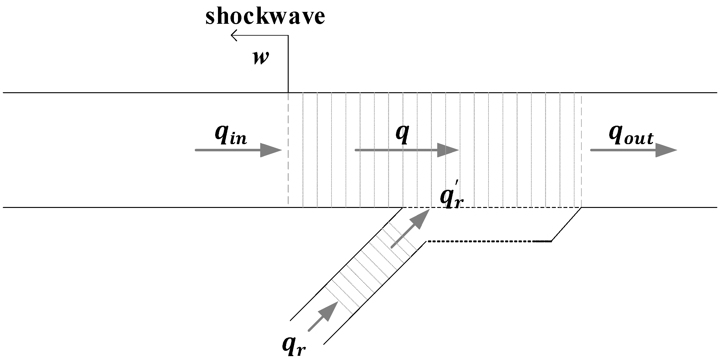
Figure 1. A freeway ramp merge with capacity drop.
Sustainability 15 02050 g001
Figure 2. An illustration of capacity drop and resulting congestion using fundamental diagram.
Sustainability 15 02050 g002
Figure 3. A ramp-merging section of an urban expressway in Shanghai with three loop detectors D1–D3.
Sustainability 15 02050 g003
Figure 4. Ramp-merging congestion and capacity drop observed from field data of D1–D3 in Figure 3: (a,b) at the location of D2; (c,d) at D1; (e,f) at D3; (a,c,e): flows (blue curves) and densities (orange curves); (b,d,f): fundamental diagrams.
Sustainability 15 02050 g004
Figure 5. A freeway stretch of 16 segments for macroscopic simulation studies.
Sustainability 15 02050 g005
Figure 6. The demand profiles for the macroscopic simulation studies.
Sustainability 15 02050 g006
Figure 7. Segment flows, densities and the fundamental diagrams based on macroscopic simulation results with and without ALINEA: (a,d,g) segment 9 (the bottleneck); (b,e,h) segment 10 (downstream of the bottleneck); (c,f,i) segment 8 (upstream of the bottleneck).
Sustainability 15 02050 g007
Figure 8. A scene of ramp merging.
Sustainability 15 02050 g008
Figure 9. A forced lane-changing model based on heuristic rules regarding the speed of Vehicle A (solid line), spacing of Vehicles A and B as well as of Vehicles A and C (dot-dashed line), and speed difference of A and C (dashed line) in Figure 8.
Sustainability 15 02050 g009
Figure 10. A stretch of Freeway A20 in the Netherlands.
Sustainability 15 02050 g010
Figure 11. The calibrated heuristic lane changing model with a potential of creating capacity drop.
Sustainability 15 02050 g011
Figure 12. The demand profiles for the microscopic simulation studies.
Sustainability 15 02050 g012
Figure 13. The layout of the first ramp-merging section in Figure 10 with 6 virtual detectors installed.
Sustainability 15 02050 g013
Figure 14. The merging process simulated by the default AIMSUN for the freeway section in Figure 13 with demands in Figure 12.
Sustainability 15 02050 g014
Figure 15. The merging process simulated by the enhanced AIMSUN for the freeway section in Figure 13 with demands in Figure 12.
Sustainability 15 02050 g015
Figure 16. Flow and density results at D1–D6 with the default AIMSUN: (a) flows; (b) densities.
Sustainability 15 02050 g016
Figure 17. Flow trajectories at D1–D 6 in Figure 13 with the enhanced AIMSUN: (a) flows; (b) densities.
Sustainability 15 02050 g017
Figure 18. A zoom-in display on Figure 17a.
Sustainability 15 02050 g018
Figure 19. Fundamental diagrams at D1–D6 with the default AIMSUN.
Sustainability 15 02050 g019
Figure 20. Fundamental diagrams at D1 to D6 with the enhanced AIMSUN.
Sustainability 15 02050 g020
Figure 21. A fundamental diagram of a reverse-lambda shape with the enhanced AIMSUN.
Sustainability 15 02050 g021
Figure 22. Flows diagrams at D1–D6 with and without ALINEA.
Sustainability 15 02050 g022
Figure 23. Densities diagrams at D1–D6 with and without ALINEA.
Sustainability 15 02050 g023
Figure 24. Fundamental diagrams at D1–D6 with and without ALINEA.
Sustainability 15 02050 g024
Table 1. The METANET Parameters.
V f ρ c r q c a p τ v κ ρ m a x V m i n δ Capacity Drop Rate
115 km/h31.5 veh/km2050 veh/h/lane20.222.510180 veh/km7.0 km/h0.915%
Table 2. The comparison of AIMSUN and enhanced AIMSUN.
Vehicle Behavior Model
AIMSUNEnhanced AIMSUN
Car-followingGippsIDM
Mandatory lane-changingGippsheuristic lane-changing model
Discretionary lane-changingGippsGipps
Disclaimer/Publisher’s Note: The statements, opinions and data contained in all publications are solely those of the individual author(s) and contributor(s) and not of MDPI and/or the editor(s). MDPI and/or the editor(s) disclaim responsibility for any injury to people or property resulting from any ideas, methods, instructions or products referred to in the content.