Article

Properties of High-Performance Materials for the Crack Repair of Segment Structures

1
Department of Civil and Airport Engineering, Nanjing University of Aeronautics and Astronautics, Nanjing 210016, China
2
SinoRoad Transportation Science and Technology Co., Ltd., Nanjing 211800, China
*
Author to whom correspondence should be addressed.
Sustainability 2023, 15(22), 15933; https://doi.org/10.3390/su152215933
Submission received: 14 September 2023 / Revised: 18 October 2023 / Accepted: 27 October 2023 / Published: 14 November 2023
(This article belongs to the Section Sustainable Materials)

Abstract

:
In order to improve the crack repair effect of high-performance segment structure crack repair materials, in this paper, we used the orthogonal test research method of four factors and three levels to analyze changes in the microstructure of crack repair materials under different material compatibility levels, followed by analysis through the performance testing of repair materials. The flow performance, setting time, compressive and flexural strength, and bonding and tensile strength were studied. The results show that (1) excessively thick epoxy polymer film affects the bond strength, an appropriate increase in the polymer–cement ratio can promote the hydration of cement, and an appropriate increase in gel material can enhance the repair function of repair material; (2) the setting time clearly increases with increases in the polymer–cement and water–cement ratios and the decrease range clearly increases with an increase in the water–cement ratio; (3) the adhesive flexural strength of epoxy polymer repair material increased the most in 28 days; and (4) the bonding tensile strength of the repair material increases first and then decreases with increases in epoxy polymer content. An appropriate increase in the polymer–cement ratio can promote cement hydration.

1. Introduction

Concrete structures are one of the most widely used structural forms in underground engineering. However, compared with above-ground space, the underground space environment is more complex, the geological and hydrological conditions are also complex and changeable, and concrete structures are more prone to a large number of cracks. According to relevant statistics, the cracking problem of underground space concrete structures in China is very serious [1,2,3], resulting in huge engineering losses. Therefore, higher requirements have been put forward for the crack resistance of concrete structures in underground space [2]. Cracks in subway tunnel segments directly endanger the safety and durability of tunnels. The core of segment crack repair lies in the adhesion and deformation coordination between the segment matrix and the repair material. The repaired segment is still subjected to the upper load and the vibration and impact load caused by train operation, which can easily cause secondary cracking and increase the complexity of repair [4,5,6].
At present, there are three main research ideas to improve the crack resistance of concrete structures in underground space: one is to add mineral admixtures to concrete; the second is to add fiber materials to concrete; and the third is to add additives to concrete [7,8]. The benefits of organic crack repair materials, such as polyurethane, acrylate, and rubber adhesives, include strong adhesion and high impermeability. Shrinkage glyceryl and epoxidation olefin are two primary categories of epoxy resin repair materials. Modified epoxy resin grouting repair solutions are popular due to their high bond strength, wide bond surface, shrinkage resistance, stability, and strength [9]. Polymer-impregnated mortar, polymer-modified mortar, and polymer-modified cement mortar [10] are the three main forms of polymer composite crack repair materials, with the latter two being the most widely used. An examination of the features of cement mortar combined with acrylic copolymer emulsion reveals that the compressive strength of the modified mortar decreases with an increase in the water-to-cement ratio, but the folding strength and bond drawing strength are improved. Additionally, it is reported that the three types of repair materials—basic repair materials, organically modified repair materials, and compositely modified repair materials—have the advantages of quick room-temperature curing, low viscosity, and strong mechanical qualities. Polymer-modified materials are frequently employed in engineering for engineering crack repair owing to their good endurance and high bond strengths. Attempts have been made by some specialists to mix polyacrylate emulsion into cement mortar in order to create a new concrete crack repair material with greater workability, higher bond strength, and longevity [11].
To date, most polymer crack repair materials are mainly applied in pavement maintenance projects. However, there is a lack of studies on concrete segment repair in environments with long-term vibration and moisture. The same repair materials are consistently employed at the same time, resulting in poor repair compatibility and an inability to guarantee the repair effect due to the various stress and damage states of segments at various locations [12]. No repair materials for patching cracks in subway segments are available on the market. Therefore, it is crucial to develop repair materials with high fluidity, high strength, rapid setting ability, good adhesion to the original matrix, and corrosion resistance based on the real state of fractures in various segments. This study investigates the effects of different polymer–cement, water–cement, sand–cement, and solid–polymer ratios on the physical properties, mechanical properties, and microstructure of the new repair material through orthogonal experiments.

2. Raw Materials and Test Methods

2.1. Test Raw Materials

The cement used in this paper was P·II 52.5 Portland cement produced by a cement plant in Nanjing, and its technical performance indicators meet the technical requirements of GB175-2007 [13] “General Portland cement” [14]. River sand was used as the main sand. The physical performance indexes meet the technical requirements of JGJ52-2006 [15] “Ordinary concrete sand and stone test standard” [14]. The new magnesia expansion agent was commissioned by a company in Shandong for processing and preparation and the water reducing agent is Rheoplus101(ST) polycarboxylate superplasticizer produced by a company. The polymer was MU-618 waterborne epoxy polymer produced by a chemical plant in Shanghai [16]. The curing agent (G) was a curing agent produced by a chemical plant in Changzhou, which is a colorless liquid with an active hydrogen equivalent of 24.3 and with 10~13 parts per 100 standard resins. The solid requirements were 7 days at 20 °C, 2 h at 20 °C, and 30 min at 100 °C. The antifoaming agent was derived from tributyl phosphate produced by a unit in Nanjing and had good compatibility with the water-reducing agent.

2.2. Test Method

(1)
Setting time: Refer to the requirements of DL/T 5126-2021 [17] “polymer modified cement mortar test procedure” [18]. The time of starting to add water was the starting time of the setting time, and the initial setting was that the test needle sank to 2–3 mm from the bottom plate. The final setting was that the settlement of the test needle did not exceed 0.5~1 mm. The initial setting and final setting times were calculated from the beginning of adding water to the initial setting and final setting states and expressed as h (hour) and min (minute).
(2)
Compressive and flexural strength: The test was based on GB/T 17671-2021 [19] “Cement mortar strength test method (ISO method)” requirements [20]. The test results were obtained by breaking a set of three prisms to obtain the average compressive strength of the six specimens, and the results were kept at 0.1 MPa.
(3)
Bonding flexural strength test: According to GB/T 17671-2021 [19] “Cement mortar strength test method (ISO method)”, after 28 days of curing, the specimen was broken. Half of the samples were put into the test mold, and the modified cement mortar was injected into the remaining half of the test mold. The specimens bonded to the modified mortar and the original cement mortar were cured to 7 days and 28 days, after which the flexural strength was tested. The flexural strength of the specimen was used to describe the bonding performance of the polymer-emulsion-modified cement mortar [21].
(4)
Infrared spectroscopy analysis: The polymer was fully stirred with a certain amount of methanol, and the graft and monomer copolymer were completely precipitated, filtered, washed, and vacuum-dried to constant weight [22]. Then it was extracted with isopropanol in a Soxhlet extractor to remove the monomer copolymer and dried to constant weight. The purified resin was coated on the pressed KBr, dried under an infrared lamp for 10 min, and tested using a Fourier transform infrared spectrometer (NEXUS670, Nicolet, Nicolet Instruments, Inc., Madison, WI, USA).
(5)
XRD test: The broken repair material was a small particle with a diameter of 1~2 mm, determined using a diamond thermogravimetric/differential thermal analyzer, produced by PERKIN-ELMER company in the United States. The sample was placed at (30~700) °C, and the heating rate was 10 °C/min for the TG and DTA tests [23].
(6)
Optical microscope analysis method: According to the requirements of DL/T 5126-2021 [17] “Polymer Modified Cement Mortar Test Procedure”, a series of observation and analysis steps were taken in the evaluation and research of the repair materials. Firstly, a small test block of 10 mm × 10 mm × 10 mm was intercepted from the repair material, and the section was observed. By observing the cross section of the test block, the uniformity and density of the repair material and the quality and integrity of the bonding interface with the mortar were evaluated. Then, the cutting surface of the test block was analyzed using an optical microscope, focusing on the pore structure in order to understand the key parameters such as porosity, pore distribution, and connectivity of the repair material. Through the study of pore structure, the quality of repair materials can be evaluated, and the formulation and properties of materials can be further improved and optimized [24].
(7)
Scanning electron microscopy (SEM): According to the requirements of DL/T 5126-2021 [17] “Test Specification for Polymer Modified Cement Mortar”, a small test block of about 10 mm × 10 mm × 5 mm was intercepted. The section of the small test block and the bonding surface between the repair material and the original matrix mortar were observed via electron microscope. The uniformity, compactness, and internal structure of the repair material were evaluated, and the bonding quality and bonding strength were judged.

2.3. Optimization Design of Concrete Segment Crack Repair Material

The proper initial setting time to enable regular construction during the tunnel maintenance skylight period was reviewed by examining the epoxy modified repair mortar’s setting time. To guarantee the quality and effectiveness of repairs, the associated features of epoxy-modified mortar were examined based on the examination of the mechanical, physical, deformation, and durability of the modified mortar with various polymer–cement ratios [25].
In order to determine the optimal ratio of repair materials, the orthogonal test of L9(34) four factors and three levels was used to analyze the influence of various factors and levels on the performance of segment repair materials. The ratio design is shown in Table 1.

3. Research of the Microstructure of Crack Repair Materials

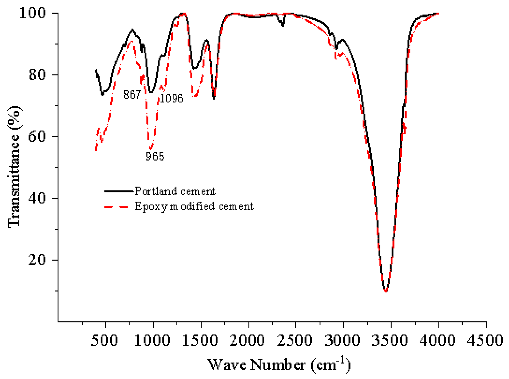
3.1. Infrared Spectroscopic Analysis of Crack Repair Materials

The stretching vibration of the Si-O bond shifts to a higher wave number as hydration time increases, the Si-O bond gradually polymerizes to the Si-O-Si bond, and the degree of silico-tetrahedral polymerization in C-S-H increases, according to infrared spectra of Portland slag cement samples at different curing ages [26]. The stretching vibration spectrum peak of the SiO bond expands and shifts towards a higher wave number as the slag percentage increases, suggesting that the Portland cement mixed with slag hydrates more slowly. On the other hand, the hydration product’s light base’s stretching vibration weakens and deviates from zero, suggesting that pure Portland cement has the largest Ca(OH)2 content.
The results of infrared spectroscopy of cement paste were found to be at 3447 cm−1. There is a hydroxvibration peak, indicating the presence of Ca(OH)2 in the system, at 3640 cm−1. There are two characteristic H2O peaks: one at 1635 cm−1 and one where the sample was maintained in air to absorb the CO2 in the air, at 1440 cm−1. There is a peak corresponding to CO32− of the carbonate salt expansion vibration; the hydration of Portland cement produces large quantities of C-S-H gel with a characteristic peak of 965–975 cm−1. As for the sharp band between 2940 cm and 2850 cm−1 in Figure 1, this may be attributed to Al2O3. After the cement slurry was modified with epoxy polymer, the peak at 965–975 cm−1 increased. While the characteristic peak of epoxy group bending vibration is at 916 cm−1, the characteristic peak of C-S-H gel suggests that the curing of epoxy resin promotes cement hydration and the production of hydrated calcium silicate. The ester group characteristic peak at 1740 cm−1 is not readily apparent. It almost vanished, signifying that the epoxy polymer finished the curing reaction. The epoxy polymer’s hydroxyl group then reacted with the calcium ions in the cement slurry to form a Ca complex, which could fill the slurry’s pores and strengthen the capillary structure, thereby enhancing the strength and compactness of the cement stone.

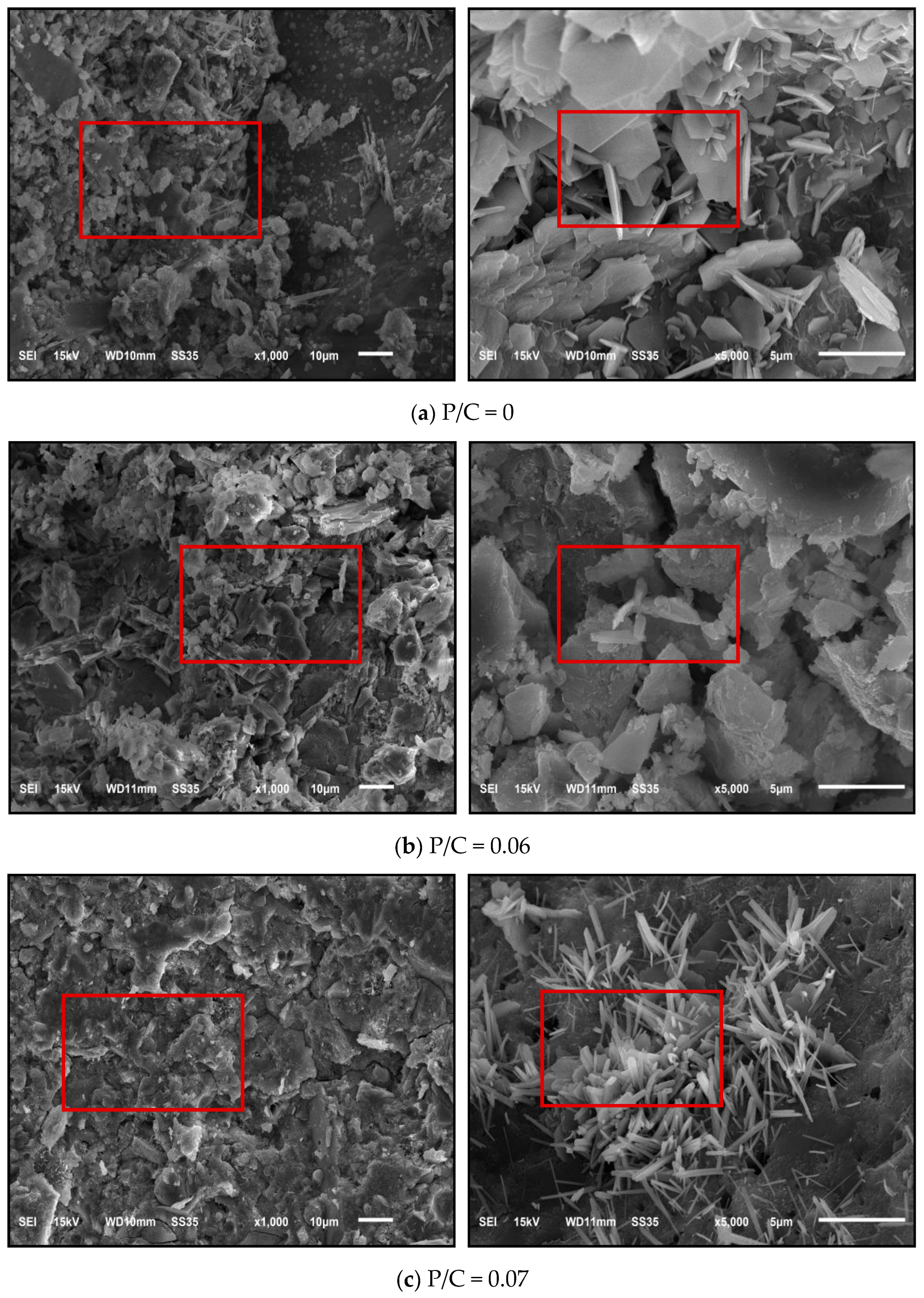
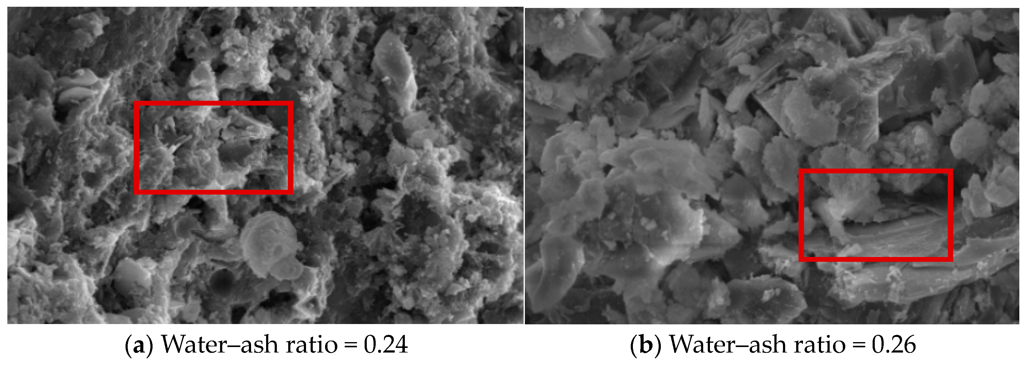
3.2. SEM Analysis of Crack Repair Materials

As can be seen from Figure 2a, when P/C = 0, that is, there are a large number of flocculation C-S-H gel and cross-connecting needle alum crystals in the SEM diagram of ordinary cement slurry, the overall appearance of cement hydration can be clearly seen at 1000 times, and Ca(OH)2 can be clearly enlarged at 5000 times. The crosses connect together, but the pores are still abundant, and there are few fillings within the pores. In contrast, the microstructure of the slurry changed significantly after the addition of different amounts of epoxy polymer.
As can be seen from Figure 2b,c, after the incorporation of epoxy polymer, in the process of cement hydration, which is the result of the water loss of the epoxy polymer, there are many mesh structures of needle calcium carbide and sheet Ca(OH)2 surrounding. The transition area interface between aggregate and cement slurry is the weakest part of the concrete repair structure. If there is a certain load stress inside the mortar, the transition area cracks easily. When epoxy is added to mortar, aggregate and cement slurry epoxy resin penetration into film during cement mortar condensation harden, making the mortar structure more dense and solidly bonded.
Furthermore, Figure 2c shows that when the polymer content increased, the epoxy polymer film’s thickness rose as well, thickening the bond transition zone of the repair interface and influencing the bond strength in the process. As a result, it is known that as the polymer increases, the bond tensile strength first rises and subsequently falls.
Figure 3 shows the SEM diagram of epoxy-polymer-modified mortar under different water–cement ratios, including needle-shaped calcium alum stone (AFt), flocculent C-S-H gel, and hexagonal plate Ca(OH)2 being the main products of cement hydration. Even if the slurry pore is filled with a lot of flocculent C-S-H gel, the hydration products and sand particles are cemented together, and the mortar mixed with epoxy polymer is denser than the unincorporated structure; the internal space gap still remains. As can be seen in the figure, the increase in aqueous ash ratio also has a certain effect on the film formation of epoxy polymer. This is in line with the findings of Liu et al. [27], who found that the density of the C-S-H gel had an impact on the strength of grout specimens. Furthermore, in the early phases, AFt and C3AH6 can boost the strength of specimens. A larger AFt development region is formed with a predominance of columnar forms at greater water-to-glue ratios. The AFt development space is narrow and needle-shaped forms form more preferentially at lower water-to-glue ratios.

3.3. X-ray Diffraction Analysis of Crack Repair Materials

The composition of repair materials and variations in hydration products were examined using X-ray diffraction. The primary hydration products of the hydration reaction were identified by a prior study as quartz (SiO), AFt, CS, CS anhydrous calcium sulfoaluminate (C4A3S), calcium sulfoaluminate hydrate (C-S-H gel), and CH. C-S-H and CH are the primary products of the hydration interaction between C2S and C3S. As the hydration reaction continues, C4A3S is gradually consumed. The specimen shows large peaks within a particular temperature range, indicating that C-S-H gel and N-A-S-H gel are generated during the hydration procedure. The specimen’s flexural and compressive strengths may be strengthened by these gels [28]. Figure 4 shows the XRD patterns of epoxy polymer mortar at different cement-to-cement ratios.
Based on the XRD analysis results of epoxy-modified mortar with different polymer-cement ratios, at 2θ (10°, 80°), calcium hydroxide (Ca(OH)2 is present), limonite (AFt), tricalcium silicate (C3S), and dicalcify silicate (C2S) are the characteristic peaks of the same phase, and the characteristic peak change of the epoxy polymer is not obvious, indicating that the epoxy polymer did not produce new products [29]. When the poly ratio is 0.06 and 0.08, the diffraction peak intensity ratios of C3S and C2S are low with epoxy polymer, indicating C3S and C2S in the modified epoxy polymer slurry, while the Ca(OH)2 and AFt diffraction peak intensities are higher than the net slurry without epoxy polymer, indicating Ca(OH)2 in the hydration product. Additionally, the content of AFt increased after the incorporation of the epoxy polymer, that is, the cement hydration obtained epoxy polymer promotion. C3S and C2S have a poly ratio of 0.05. The diffraction peak has a lower intensity ratio of 0.07 but has a higher Ca(OH)2. The diffraction peak intensity of AFt shows that an appropriately increasing cement ratio can promote cement hydration [30].

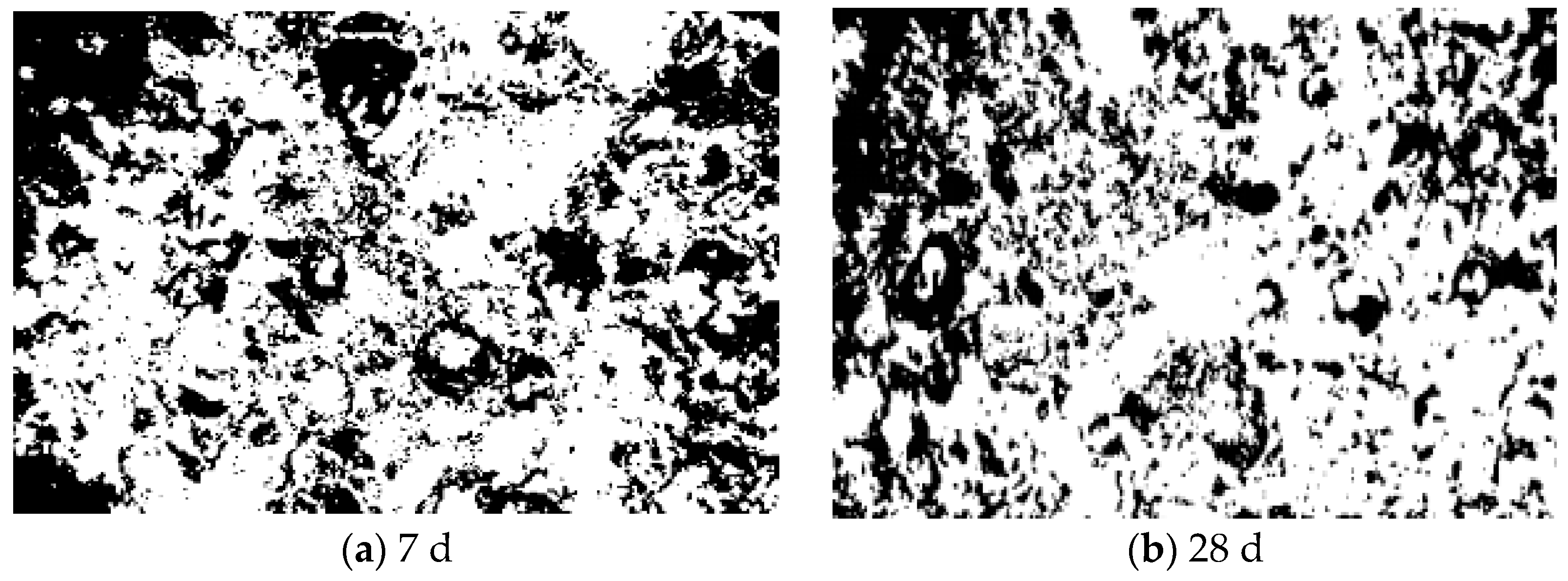
3.4. Analysis of Surface Morphology of Crack Repair Materials

Figure 5 shows the surface morphology of the crack repair materials cured to different ages. After image J treatment, the average pore diameters at 7 days and 28 days were 0.875 mm and 0.775 mm, respectively. It can be seen from Figure 5a that there are many bubbles in polymer repair materials. Under the action of the defoaming agent, most break, but part of the hole structure diameter is still very large, which to some extent affects the strength of polymer repair materials. In practical engineering, the volume of water absorption rate is larger than that of general repair mortar, which may affect the repair effect and also affects the viscosity and deformation properties of modified mortar (Figure 5b). The bubbles in the polymer repair materials, silicon ash, expansion agent, and cement mortar improve the compaction and strength of the polymer repair materials for 28 days, increase the shrinkage deformation of the hydration process, reduce the deformation of the polymer repair materials, and bond with the original concrete to achieve efficient repair. Therefore, adding appropriate cementing materials to the repair materials can enhance the repair effect of the repair materials.

4. Study of the Properties of the Segment Crack Repair Materials

The physical and mechanical properties of epoxy-modified mortar were confirmed based on orthogonal design in conjunction with the findings of the microstructure study of restorative materials. The properties of patched materials under varying solid ratios, as well as the ratio of water ash-to-ash ratio, were examined and analyzed in light of the addition of suitable cementing materials [31,32].

4.1. Study of the Physical Properties of the Segment Crack Repair Materials

From Table 2 and Table 3, the four factors are flow: A = B > C > D; setting time: B > A > D > C; 7 d folding strength: B > A > C > D; 7 d compressive strength: A > B > D > C; 28 d folding strength: D > B > A > C; 28 d compressive strength: C > B > A > D.

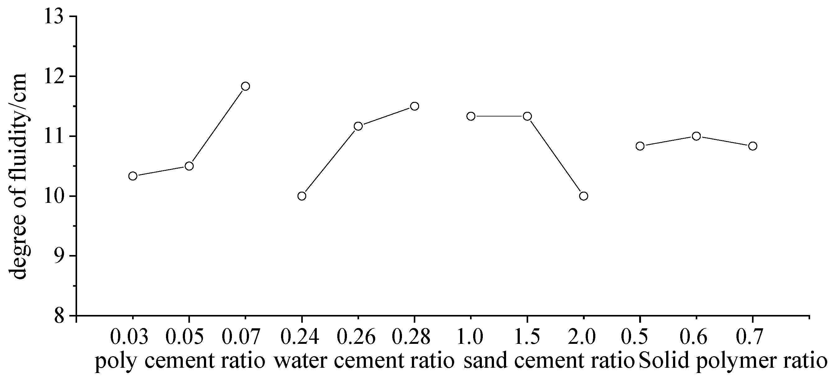
4.1.1. Study of the Fluidity of Crack Repair Materials

Figure 6 shows the influence of different factors on the fluidity of the epoxy-modified mortar. As visible from the figure, fluidity increases with the poly ratio. When the poly ratio is 0.07, flow degree has a significant increase of 11.5 cm; the greater the water–ash ratio, the greater the mobility degree. When the water–ash ratio is 0.28, the maximum flow degree reaches 10.5 cm; with sand–ash ratios of 1.0 and 1.5 and little variation in mobility, the maximum flow degree stays at around 10.8~10.9 cm. When the sand–ash ratio is 2.0, this causes the most significant flow degree reduction, down to 9.1 cm. The flow degree increases with the fixation ratio and then decreases; at a solid–poly ratio of 0.6, the flow degree is 10.5 cm, the effect of the solid–poly ratio on the flow degree is not obvious.
Due to the “ball” effect, the fluidity of the repair mortar increases, and the epoxy particles indicate polarity. The more epoxy resin, the stronger the dispersion, and the flocculent structure in the original cement slurry is dispersed, releasing the internal moisture and increasing the fluidity of the repair material [33].

4.1.2. Study of the Setting Time of Crack Repair Materials

The important technical index of concrete repair material is the setting time [34]; construction efficiency has a close relationship between construction efficiency and economic benefit and setting time. The construction period of crack repair in subway tunnels is concentrated at night, which means the repair time is short. Therefore, there are certain requirements for the setting time of repair materials, and it is of great practical significance to study the initial setting time of repair materials [35,36].
Figure 7 illustrates how various factors affect the epoxy-modified mortar’s initial setting time. As the poly–ash and water–ash ratios increase, the setting time of the repair material increases significantly: at a poly ratio of 0.03, the setting time was 131 minutes; at a poly ratio of 0.07, the setting time was 190 minutes. Setting times become shorter as the water-to-cement ratio rises; for example, 149 minutes were needed when the water–ash ratio was 0.26. The sand–ash ratio increases in a trend that is initially increasing and then reducing, although the shift was not immediately apparent; at 1.0, the setting time was 15 minutes, and at 2.0, it was 146 minutes. The diagram indicates that in order to attain the best economic benefits, the poly–ash ratio and the water–ash ratio should be appropriately increased or decreased in order to manage the setting time of the repair material.
The addition of epoxy material to repair mortar causes the epoxy resin to wrap and disperse the cement particles, forming a film on the cement hydration surface that slows down and eventually condenses the cement hydration. This inhibition of epoxy resin is the primary factor influencing the setting time of epoxy-modified mortar, as it increases with increased epoxy dosage while also slowing down the cement hydration speed.

4.2. Study of the Mechanics and Deformation Properties of Crack Repair Materials

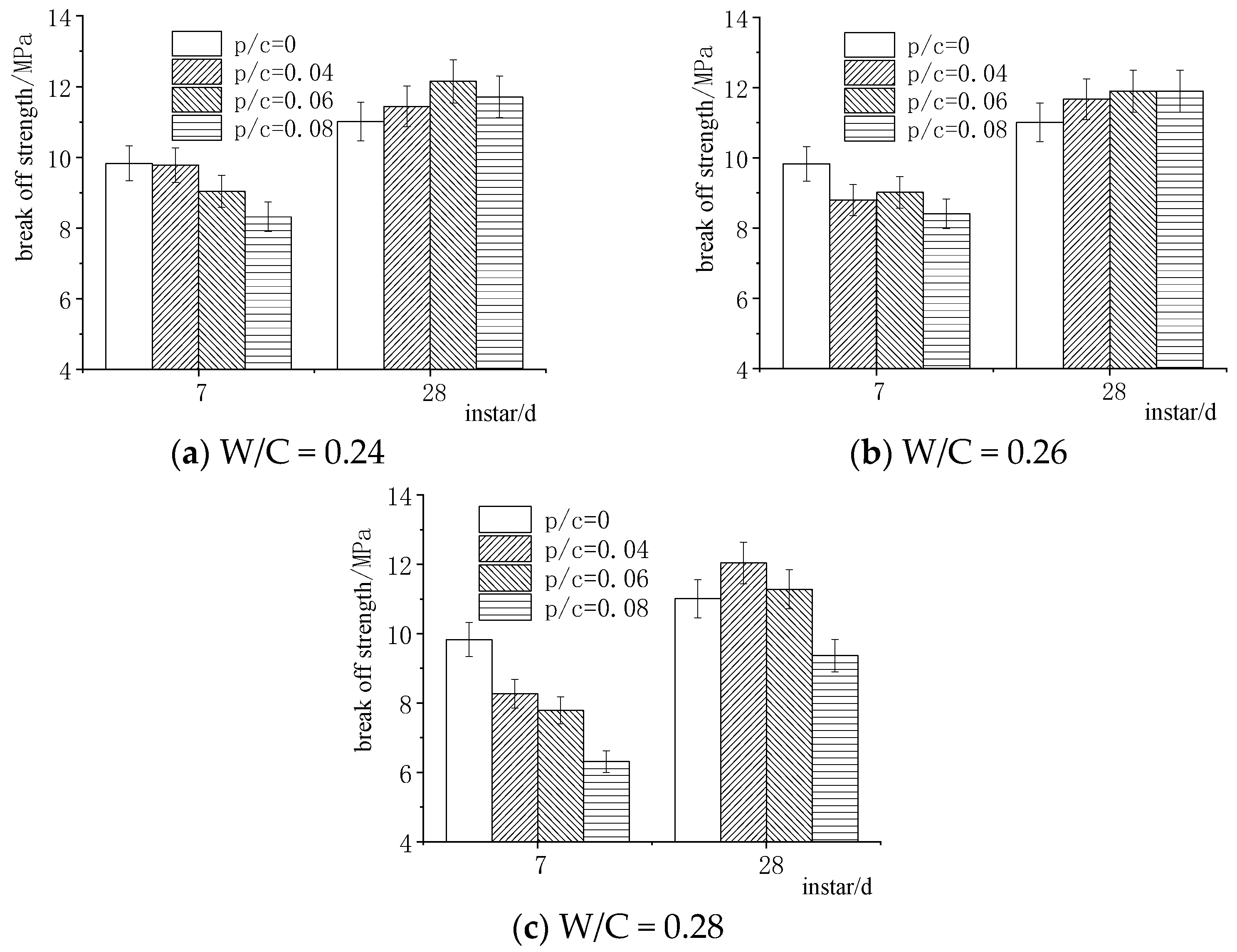
4.2.1. Study of Compression and Folding Strength of Crack Repair Materials

Figure 8 shows the effect of the poly–cement ratio on the folding strength of 7 and 28 days of epoxy-modified mortar at different water–cement ratios.
Figure 8a: The folding strength of epoxy-modified mortar after seven days is 9.1 MPa, 0.04% lower than the unmodified mortar specimen, and essentially unchanged when the water–ash ratio was 0.24 and the poly–ash ratio was 0.03. When the poly–ash ratio was 0.07, 14.6% lower than the unmodified specimen, and the incorporation of epoxy resin increased, the folding strength fell to 8.1 MPa. When the ash ratio was 0.05, the folding strength of 28 days increased to 12.9 MPa by 9.8%; while the folding strength at an ash ratio of 0.03 was 11.8 MPa, the minimum increase was 3.8%; and when the ash ratio was 0.07, there was an increasing of 6.2% to 12.1 MPa. The folding strength of the 28-day epoxy-modified mortar is greater than that of the unmodified mortar with an increased amount of epoxy resin.
Figure 8b shows a ratio of 0.26 for water to cement. When the amount of epoxy mixture was increased, the folding resistance decreased initially and then increased again. The 28-day folding resistance is greater than that of the unmodified specimen. At ratios of 0.03, 0.05, and 0.07, the 7-day anti-folding intensity was 10.2%, 7.9%, and 14.1% lower than that of the unmodified specimens, respectively; the intensity values were 8.9 MPa, 9.2 MPa, and 8.6 MPa. With the inclusion of epoxy, the rise increased. Over time, however, growth slowed. At 0.03, 0.05, and 0.07 poly–gray ratios, the 28-day folding resistance strength increased by 6.2%, 7.9%, and 8%, respectively, in comparison to the unmodified specimens; the resistance strength values were 11.9 MPa, 12.2 MPa, and 12.1 MPa.
Figure 8c illustrates how the folding resistance strength of the modified mortar after seven days is significantly lower than that of the unmodified mortar when the water–ash ratio is 0.28. This decrease in resistance strength occurs gradually as the amount of epoxy incorporation increases. At 0.03, 0.05, and 0.07, the resistance strengths were 7.9 MPa and 6.2 MPa, 15.5%, 20.9%, and 35.4% lower than that of the unmodified mortar; at 28 days, the folding strengths were 12.8 MPa and 12.1 MPa, 9.1% and 2.3% more than the unmodified mortar; however, at the poly–gray concentration ratio of 0.07, the resistance strength decreased to 9.9 MPa, a decrease of 14.4%. The samples demonstrated a marked decline in bending strength as epoxy content increased; at a particular mixing level, the antifolding strength dropped even further below that of the mortar that was left unaltered.
According to Figure 8’s overall analysis, the folding strength of epoxy-polymer-modified repair mortar decreases over a period of seven days when the water–cement ratio increases. Nevertheless, during the 28 days, 7 days were mostly spent in water, preventing the epoxy resin’s film from forming. The water-to-cement ratio was the primary factor influencing the folding strength. Less relative humidity, a test piece with accelerated water loss, the formation of an epoxy film, and the enhancement of the resistance discount strength all play a part in the test specimen’s post-stage standard sample. This research reveals that while the antifolding strength of the epoxy-modified mortar increases significantly faster than the unmodified mortar, the folding resistance strength increases more slowly (7~28d). The primary reason for this is epoxy resin’s retraction; the more of it there is, the more significant the effect. The modified mortar’s early strength was low due to incomplete cement hydration and an incomplete epoxy resin film. However, over time, the cement particles hydrated and the epoxy resin film was completed, creating a mesh space structure, bonding fine aggregate and cement hydration products together, and improving the internal structure. All in all, the modified mortar’s 28-day resistance strength increased significantly when compared to its early state.
The compressive strength of the epoxy-modified mortar is greater than that of the unmodified mortar when the water–ash ratio was 0.24. The compressive strength of the epoxy-modified mortar increased by 8.1% after 7 days when the poly ratio was 0.03. The ash ratios of 0.05 and 0.07 increased by 10.9% and 2.9%, respectively, when compared to the unmodified specimen. The compressive strength of the 28-day modified mortar is higher than that of the unmodified specimen, and it gradually increased with the increase in epoxy incorporation. A significant increase was observed when the poly–ash ratios were 0.03, 0.05 and 0.07, which increased the compressive strength of the unmodified mortar by 18.4%, 30.1%, and 35.8%, respectively.
According to Figure 9b, the compressive strengths at 7 and 28 days were higher than that of the unmodified mortar with the increase in epoxy content. When the poly–ash ratio was 0.03, 0.05, and 0.07, the compressive strength at 7 days increased by 15.5%, 19.6%, and 0.4%; at 28 days, it increased by 21.3%, 39.5%, and 25.5%, respectively. From Figure 9c, when the poly–ash ratio was 0.05, the 7-days strength increased by 5.4% and 17.7% and 0.9% and 0.07% compared to poly–ash ratios of 0.03 and 0.07, respectively, with epoxy incorporation. When the poly–ash ratio was 0.03, 0.05, and 0.07, it increased by 26.3%, 25.9%, and 0.3% respectively, with the increase in epoxy incorporation.
Figure 9’s overall comparative analysis leads to the conclusion that while the compressive strength of 28 days is not readily apparent, the compressive strength of 7 days steadily decreases as the water–ash ratio rises. The compressive strength was not appreciably decreased until the water–ash ratio reached 0.28.
According to our experiments, the modified mortar’s compressive strength is greatly increased by the increase in cement hydration and epoxy resin in the water late in the standard curing environment, when water evaporation occurs and the epoxy polymer mesh space structure gradually forms.

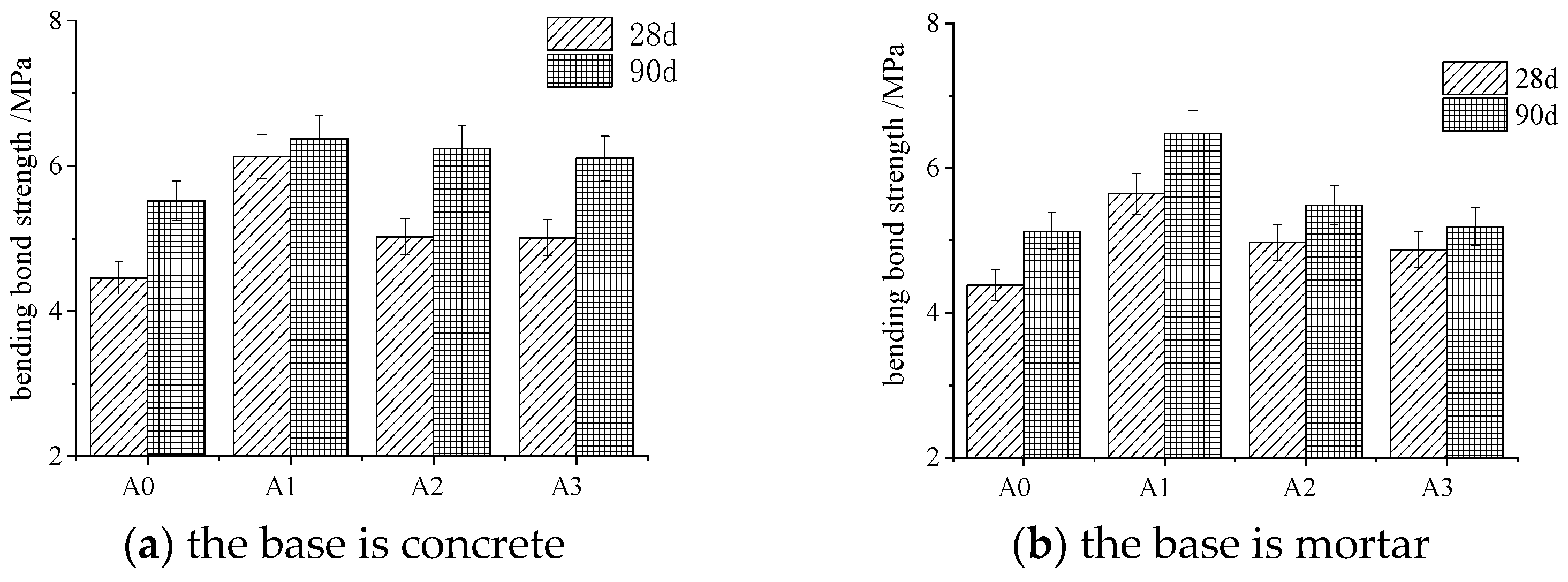
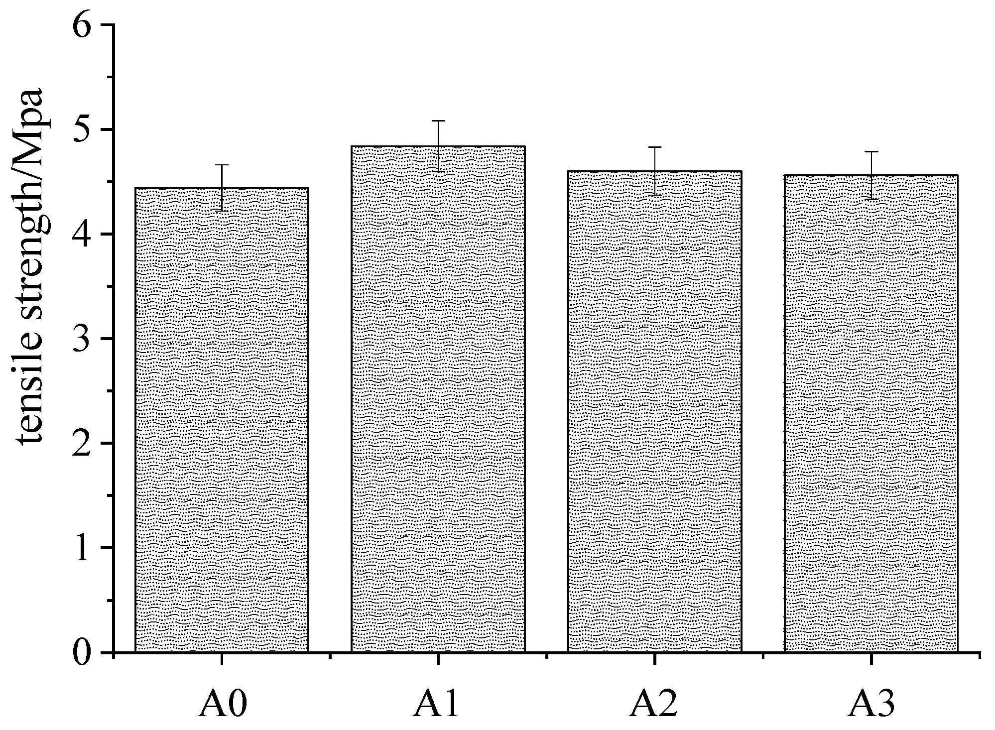
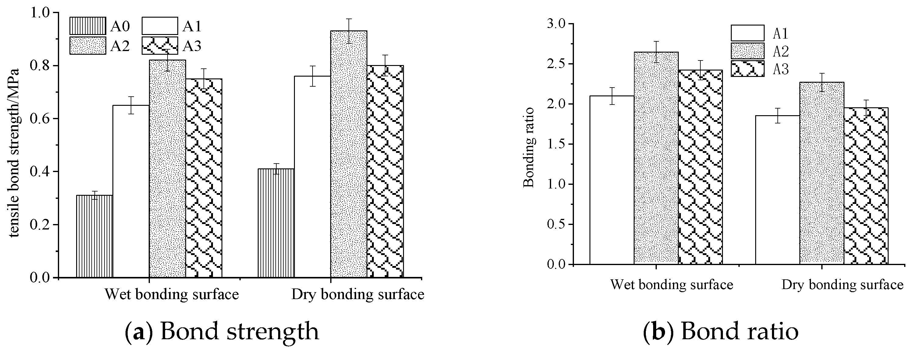
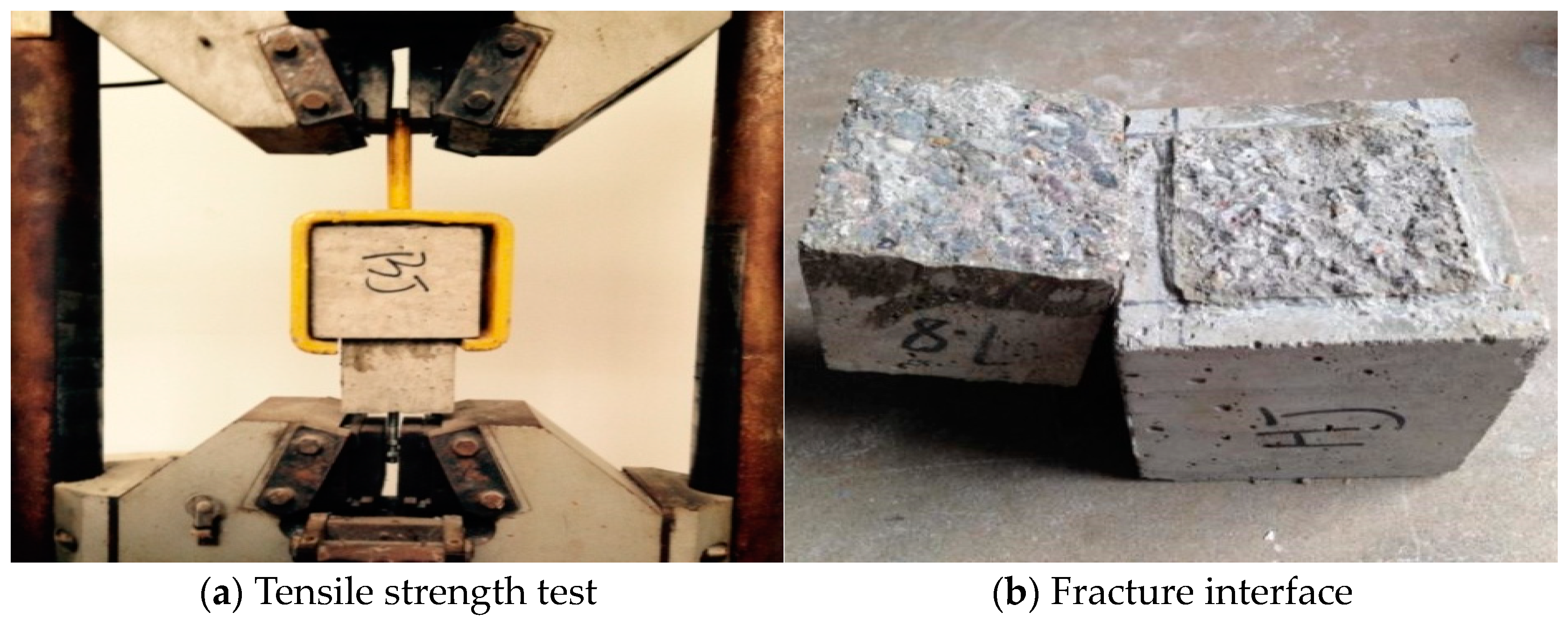
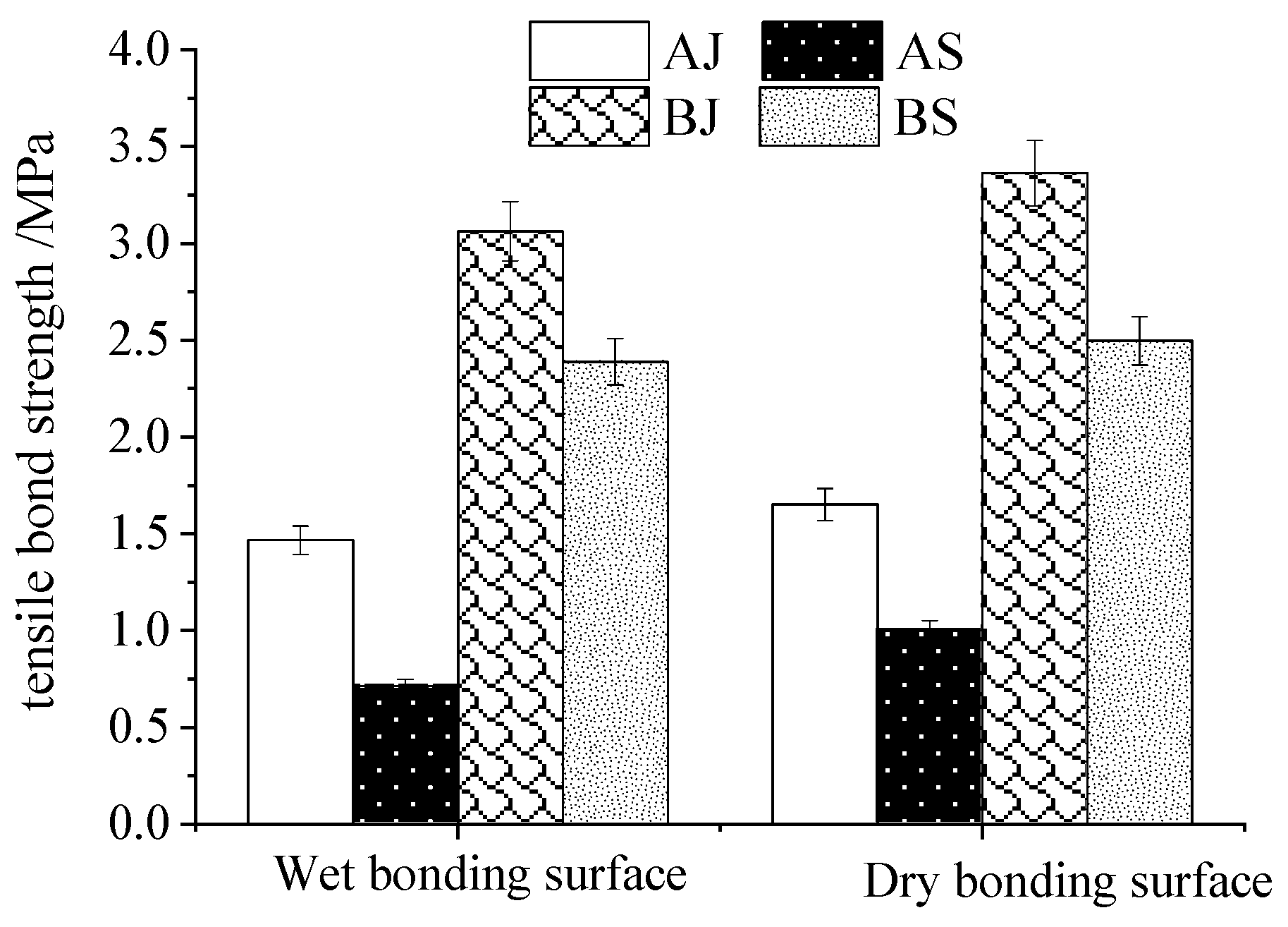
4.2.2. Binding and Tensile Strength of Crack Repair Materials

A few appropriate ratios were chosen for the bonding and tensile strength of repair materials based on the analytical results of orthogonal trials. These were the solid polymer ratio (0.6), sand–ash ratio (1.5), water–ash ratio (0.28), and ES 1–ash ratio (0.7).
The bending strength of the bonded specimens at 28 d and 90 d is higher than that of the unaltered material A0, as shown in Figure 10a, and it also rose noticeably with age. The bond folding resistances of specimens A1, A2, and A3 were 5.7 MPa, 4.9 MPa, and 4.8 MPa at 28 days and 6.4 MPa, 6.2 MPa, and 6.1 MPa after 90 days, respectively. Throughout the course of this experiment, the bonding strength of the modified repair material steadily declined as the poly ratio increased after 28 and 90 days.
Figure 10b illustrates how the bonding strength of the modified repair material specimen, which is based on mortar, increased dramatically with age and was larger than that of the unmodified specimen, ES 0. The findings demonstrate that the specimens A1, A2, and A3 had bond strengths of 126.8%, 111.3%, and 109.9% of A0 at 28 days, or 5.8 MPa, 5.1 MPa, and 4.9 MPa, respectively; after 90 days, the specimens’ bond strengths climbed to 124.7%, 105%, and 100.2% of A0, respectively. The strength of mortar’s bond is enhanced by the inclusion of resin. In the context of this test, the anti-folding bonding strength also fell as the poly–ash ratio rose following an increase in the poly ratio.
Previous studies indicated that cement mortar possesses specific bonding properties [37,38], and that mortar’s bonding resistance strength increases with the addition of epoxy. As the old mortar surface accumulate fine aggregate, the pores of the old mortar surface may be blocked, preventing the new repair material from fully entering the original pores and causing the "lack of slurry" phenomenon, which lowers the bond strength between the old and new interfaces. After vibration during the repair process, the repair material at the interface may squeeze.
As can be seen from Figure 11, the tensile strength of epoxy polymer mortar is larger than that of unmodified mortar; it decreased with the increase in polymer incorporation, as ES1, ES2, and ES3 are 107.5%, 102%, and 101.8% of ES0, respectively.
The repair material used in the concrete crack repair project lacks the bonding strength necessary to prevent failure or material peeling off. Figure 12 shows how to repair the adhesive surface in the dry and wet states of bonding tensile strength difference. Subway tunnels frequently experience dry and wet alternating environments, with segments or lining cracking with dry cracks and also having wet cracks. In a wet environment, if enough moisture affects the bonding surface transition area’s water–ash ratio, this reduces the bonding strength of the repair material. Figure 13 displays the specimen fracture surface morphology and the bond tensile strength test. It is evident that in certain specimens, the bonding surface is not the fracture surface, resulting in a bond tensile strength that exceeds the specimen’s tensile strength.
The bond tensile strength findings are evident from the actual test and indicate that the polymer mixing content variation did not considerably increase the bond tensile strength. According to the preferred mix ratio of the test process, as shown in Table 4, the bond tensile strength of cement net mortar and mortar, polymer net mortar, and mortar are compared and analyzed.
Different bond tensile strengths of repair materials in wet and dry settings are shown in Figure 14. However, whether in wet or dry conditions and with the minimum bond tensile strength after epoxy-modified slurry repair with the minimum amount of mortar, that is, different ratios of AJ, AS, BJ, and BS in a wet environment compared to in a dry environment of 85.7%, 70.4%, 89.8%, and 94.3% those values in the dry environment, respectively, it can be seen that the net slurry and mortar mixed with polymer are less affected by a wet environment, while the cement clean slurry and mortar are greatly affected by dry and wet environments, showing that a wet environment affects the bond tensile strength of the repair material. The reason for this is that a wet environment affects the bonding strength of polymer-modified material, in that sufficient water can affect the water loss of polymer into film; thus, the polymer cannot wrap the cement particles to block the cracks in a timely manner, affecting the bond strength. The reason this affects the bonding strength of the cement net slurry and mortar is the existence of excess water on the bonding surface; the cement slurry particles fail to adequately enter the crack interior, and at the same time, the presence of water also increases the interface water–ash ratio, affect the strength [39].
Figure 14 further illustrates how much stronger the bonds between BJ and BS are than those between AJ and AS. BJ is 208.8% of AJ and BS is 335.8% of AS in the wet state. In a dry environment, BS is 249.6% of AS and BJ is 203.7% of AJ, suggesting that the doped polymer can greatly increase the repair material’s bond tensile strength.

5. Conclusions

In this study, we examined the impact of various ratios of water to cement, polymer to cement, and other variables on the mechanical and physical characteristics of polymer repair materials. In order to examine the bonding, tensile strength, compressive and flexural strength, and bonding strength of the repair materials, the proper mix ratio was chosen. The following are the primary conclusions:
(1)
From the results of infrared spectroscopy, it can be found that the Ca-containing complex produced by the epoxy polymer when the curing reaction is completed can fill the capillary pores in the cement paste and improve the capillary pore structure. The addition of epoxy polymer can improve the strength and compactness of cement stone;
(2)
The thickness of the epoxy polymer film increases with the increase in polymer, and the bonding tensile strength increases first and then decreases with the increase in polymer. The water–cement ratio can also affect the film formation of the epoxy polymer;
(3)
The results of X-ray diffraction show that epoxy polymer can effectively promote the hydration of cement, and the polymer–cement ratio can be appropriately increased in the repair material;
(4)
After the reaction of cementitious material and cement mortar, the density and strength of the polymer repair material for 28 days are improved to a certain extent, and the deformation of the polymer repair material is reduced. Therefore, adding appropriate cementitious material to the repair material can enhance the repair effect of the repair material;
(5)
The fluidity of the repair material increases with the increase in the polymer–cement ratio, and the greater the water–cement ratio is, the greater the fluidity is. When the polymer–cement ratio is 0.07, the water–cement ratio is 0.28, the sand–cement ratio is 1.5, and the solid–polymer ratio is 0.6, the fluidity of the repair material is the best;
(6)
The 28-day flexural strength of polymer repair materials (except when the water–cement ratio is 0.3 and the polymer-cement ratio is 0.08) is higher than that of ordinary cement mortar, and the increase is about 5−10%, but the 7-day flexural strength is lower than that of ordinary cement mortar. When the water–cement ratio is 0.24 or 0.26, the flexural strength of the polymer–cement ratio 0.05 is the highest, but when the water–cement ratio is 0.28, the flexural strength of the polymer–cement ratio 0.03 is the highest;
(7)
The bonding flexural strength of epoxy polymer repair material is greatly improved compared to that of ordinary mortar. Whether the base is concrete or mortar, the bonding flexural strength is the highest when the polymer–cement ratio is 0.07, the water–cement ratio is 0.28, the sand–cement ratio is 1.5, and the solid–polymer ratio is 0.6;
(8)
In both wet and dry situations, the repair material’s bonding tensile strength is greater than that of regular mortar. The bonding tensile strength rose initially and subsequently fell as the epoxy polymer content rose. In addition, the bonding tensile strength in a damp environment is lower than in a dry one. The inclusion of epoxy polymer can greatly enhance the bonding ability of the repair material, allowing the solid polymerization ratio to be raised to 0.6. This is because epoxy polymer paste and mortar are less susceptible to moisture than regular cement paste and mortar.

Author Contributions

X.S., resources, investigation, writing—original draft, editing and formal analysis; P.G., supervision, validation, methodology and funding acquisition; J.Z., G.L., D.X., Z.Z. and T.G., data curation, project administration. All authors have read and agreed to the published version of the manuscript.

Funding

This project was supported by The Science and Technology Project of Jiangsu (BK20200429), the Science and Technology Project of Shanxi Province (2023-JC-YB-375), China TIESIJU Civil Engineering Group Co., Ltd., (22040), China Design Group Co., Ltd., (21498), Nanjing Huizhu Information Technology Research Institute Co., Ltd., (22088), Suzhou Rail Transit, and Shanxi Technology Innovation Center project (202104010911016).

Institutional Review Board Statement

Not applicable.

Informed Consent Statement

Not applicable.

Data Availability Statement

The data presented in this study are available on request from the corresponding authors.

Conflicts of Interest

Authors Zhixiang Zhang and Ting Gan were employed by the company SinoRoad Transportation Science and Technology Co., Ltd. The remaining authors declare that the research was conducted in the absence of any commercial or financial relationships that could be construed as a potential conflict of interest.

References

  1. Chen, M.; Gao, P.; Geng, F.; Xu, S.-Y.; Chen, X. Mechanical and smart properties of carbon fiber and graphite conductive concrete for internal damage monitoring of structure. Constr. Build. Mater. 2017, 142, 320–327. [Google Scholar] [CrossRef]
  2. Eng, T.Z.; Gao, P.; Zhu, Q.; Zhu, A. Experimental and Numerical Modeling on FRP and PM Confinement Tilt Fulcrum RC Segments under Humid and Fatigue Conditions. KSCE J. Civ. Eng. 2019, 23, 3409–3419. [Google Scholar] [CrossRef]
  3. Toshinori, K.; Satoshi, T. Applicability of AC impedance method for measuring time-variant corrosion rate to cracked and crack-repaired reinforced concrete. Mater. Struct. 2023, 56, 20. [Google Scholar]
  4. Gao, P.; Lu, X.; Yan, Y.; Dong, B.; Li, X. Effect of composite mineral admixtures on restraining alkali-silica reaction. J. Nanjing Univ. Aeronaut. Astronaut. 2006, 23, 120–124. (In English) [Google Scholar]
  5. Camille, A.; Pauls, D. Experimental study of epoxy repairing of cracks in concrete. Constr. Build. Mater. 2007, 1, 157–163. [Google Scholar]
  6. Houli, X. Study on Preparation and Properties of New Bonding Mortar. Master’s Thesis, Chongqing University, Chongqing, China, 2001. [Google Scholar]
  7. Sumaiya, A.; Dieu, N.Q.; Arnaud, C. Evaluation of cracking potential parameters for low to high grade concrete with fly ash or slag. Constr. Build. Mater. 2022, 350, 128891. [Google Scholar]
  8. Liu, Q.; Hu, Z.; Wang, X.; Zhao, H.; Qian, K.; Li, L.; Meng, Z. Numerical study on cracking and its effect on chloride transport in concrete subjected to external load. Constr. Build. Mater. 2022, 325, 126797. [Google Scholar] [CrossRef]
  9. Surianinov, M.; Andronov, V.; Otrosh, Y.; Makovkina, T.; Vasiukov, S. Concrete and Fiber Concrete Impact Strength. Mater. Sci. Forum 2020, 1006, 101–106. [Google Scholar] [CrossRef]
  10. Vivas, J.C.; Zerbino, R.; Torrijos, M.C.; Giaccio, G. Effect of the fibre type on concrete impact resistance. Constr. Build. Mater. 2020, 264, 120200. [Google Scholar] [CrossRef]
  11. Chen, L.; Zheng, S.; Li, X.; Cheng, Z.; Wang, X. Experimental Investigation of Cracking and Impact Resistance of Polymer- and Fiber-Enhanced Concrete for Ultra-Thin Whitetopping. Polymers 2022, 14, 4472. [Google Scholar] [CrossRef]
  12. Sheng, Y.; Li, S. Research on the technologies of cracking-resistance of mass concrete in subway station. AIP Conf. Proc. 2018, 1944, 020008. [Google Scholar]
  13. GB175-2007; Common Portland Cement. China National Standardization Administration: Beijing, China, 2017.
  14. Shen, H.; Gao, P.; Liu, H. Mechanism and Process of Sulfate Attack on Roller Compacted Concrete with MgO Expansive Agen. J. Nanjing Univ. Aeronaut. Astronaut. 2016, 33, 633–638. [Google Scholar]
  15. JGJ52-2006; Standard for technical requirements and test method of sand and crushed stone(or gravel) for ordinary concrete. China Building Industry Press: Beijing, China, 2006.
  16. Zhang, Y.; Wang, Y.; Ren, Z. Experimental Study on the Properties of Mixed-Fiber Concrete Shield Tunnel Segments Subjected to High Temperatures. Fire 2023, 6, 17. [Google Scholar] [CrossRef]
  17. DL/T 5126-2021; Test code for polymer modified cement mortar. China Research Institute of Water Resources and Hydropower: Beijing, China, 2021.
  18. Li, P.; Jia, Z.; Zhang, M.; Gao, X.; Wang, H.; Feng, W. Bending failure performance of a shield tunnel segment based on full-scale test and numerical analysis. Front. Struct. Civ. Eng. 2023, 17, 1033–1046. [Google Scholar] [CrossRef]
  19. GB/T 17671-2021; Test method of cement mortar strength (ISO method). China Building Materials Federation: Beijing, China, 2022.
  20. Liu, D.; Guo, Y.; Yao, X. Interfacial Behaviour of Shield Tunnel Segment Strengthened by Thin Plate at Inner Surface. Adv. Mater. Sci. Eng. 2022, 2022, 7715844. [Google Scholar] [CrossRef]
  21. Lu, X.; Geng, F.; Zhang, H.; Chen, X. Influence of MgO-type Expansive Agent Hydration Behaviors on Expansive Properties of Concrete. J. Wuhan Univ. Technol. Mater. Sci. 2011, 26, 345–347. [Google Scholar] [CrossRef]
  22. Zhang, X.; Jin, H.; Yu, S.; Bi, X.; Zhou, S. Analysis of bending deflection of tunnel segment under load- and corrosion-induced cracks by improved XFEM. Eng. Fail. Anal. 2022, 140, 106576. [Google Scholar] [CrossRef]
  23. Zhang, Y.; Karlovšek, J.; Liu, X. Identification Method for Internal Forces of Segmental Tunnel Linings via the Combination of Laser Scanning and Hybrid Structural Analysis. Sensors 2022, 22, 2421. [Google Scholar] [CrossRef]
  24. Huang, L.; Wu, G. Study on the selection of inner diameter in shield tunnel segment in soft soil stratum. J. Phys. Conf. Ser. 2021, 2044, 012176. [Google Scholar] [CrossRef]
  25. Koga, D.R.; Lin, Q.W.; Zhang, X.S.; Han, W.; Jiang, Y.J.; Luan, H.J. Frame structure analysis model for the effect of typical tunnel diseases on lining structure. IOP Conf. Ser. Earth Environ. Sci. 2021, 861, 042114. [Google Scholar] [CrossRef]
  26. Jia, Q.; Wang, Y. Study on Calcium Carbonate Deposition of Microorganism Bottom Grouting to Repair Concrete Cracks. Sustainability 2023, 15, 3723. [Google Scholar] [CrossRef]
  27. Xiao, J.; Li, H.; Zhu, H.; Dang, Y. Hydration products of slag silicate composite cementitious materials are analyzed by infrared and nuclear magnetic techniques. J. Mater. Sci. Eng. 2018, 174, 644–649. [Google Scholar]
  28. Ng, H.J.; Al Bakri Abdullah, M.M.; Tan, S.J.; Sandu, A.V.; Hussin, K. Characterisation and understanding of Portland cement mortar with different sizes of bottom ash. Adv. Cem. Res. 2018, 30, 66–74. [Google Scholar] [CrossRef]
  29. Liu, J.; Han, D.; Zhang, Z. Single fly ash and slag powder on the hydration process and strength of magnesium phosphate cement. Silic. Bull. 2023, 42, 2472–2478. [Google Scholar]
  30. Liu, P.; Yao, S.; Dong, X.; Fu, Y.; Li, D. Microstructure and Performance Analysis of Permeable Coagulation of Mineral Compounds. Silic. Bull. 2023, 42, 25048. [Google Scholar]
  31. Uotinen, L.; Siren, T. Elastoplastic Modelling of an In Situ Concrete Spalling Experiment Using the Ottosen Failure Criterion. J. Eng. 2017, 2017, 4723017. [Google Scholar] [CrossRef]
  32. Kala, Z. Stability of Von-Misses Truss with Initial Random Imperfections. Procedia Eng. 2017, 172, 473–480. [Google Scholar] [CrossRef]
  33. Sun, Y.; Gao, P.; Geng, F.; Li, H.; Zhang, L.; Liu, H. Thermal conductivity and mechanical properties of porous concrete materials. Mater. Lett. 2017, 209, 349–352. [Google Scholar] [CrossRef]
  34. Wu, Z.; Shi, C.; Gao, P. Effects of Deicing Salts on the Scaling Resistance of Concrete. J. Mater. Civ. Eng. 2015, 27, 04014160–04014165. [Google Scholar] [CrossRef]
  35. Hassan, N.; Sherif, A.; Zamarawy, A. Finite element analysis of reinforced concrete beams with opening strengthened using FRP. Ain Shams Eng. J. 2017, 3, 531–537. [Google Scholar] [CrossRef]
  36. De Lorenzis, L.; Fernando, D.; Teng, J.-G. Coupled mixed-mode cohesive zone modeling of interfacial debonding in simply supported plated beams. Int. J. Solids Struct. 2013, 50, 2477–2494. [Google Scholar] [CrossRef]
  37. Gao, P.; Lu, X.; Li, X.; Geng, F.; Le, J.; Chen, W. Study on Novel Repair Materials and Techniques for Airport Pavement. In Proceedings of the International Conference on Transportation Engineering, Chengdu, China, 22–24 July 2007. [Google Scholar]
  38. Gao, P.W.; Wu, S.X.; Lu, X.L.; Deng, M.; Lin, P.H.; Wu, Z.R.; Tang, M.S. Soundness evaluation of concrete with MgO. Constr. Build. Mater. 2007, 21, 132–138. (In English) [Google Scholar] [CrossRef]
  39. Gao, P.; Lu, X.; Jin, S.; Zhang, H.; Guo, C. Using a new composite expansive material to decrease deformation and fracture of concrete. Mater. Lett. 2008, 62, 106–108. [Google Scholar]
Figure 1. 28 d infrared spectrum of ordinary and water-based epoxy-resin-modified cement.
Sustainability 15 15933 g001
Figure 2. SEM diagram of polymer-modified mortar with different poly ratios.
Sustainability 15 15933 g002
Figure 3. SEM diagram of epoxy-polymer-modified mortar under different water–cement ratios.
Sustainability 15 15933 g003
Figure 4. XRD of epoxy-modified mortar with different pozzolanic ratios.
Sustainability 15 15933 g004
Figure 5. Surface morphology of epoxy-modified mortars of different ages (after treatment).
Sustainability 15 15933 g005
Figure 6. Influence of different factors on fluidity of epoxy-modified mortar.
Sustainability 15 15933 g006
Figure 7. Influence of different factors on initial setting time of epoxy-modified mortar.
Sustainability 15 15933 g007
Figure 8. Effect of aggregate cement ratio on flexural strength of repair mortar at 7 and 28 days under different water–cement ratios.
Sustainability 15 15933 g008
Figure 9. Effect of aggregate cement ratio on compressive strength of repair mortar at 7 and 28 days under different water–cement ratios.
Sustainability 15 15933 g009
Figure 10. Bond flexural strength of epoxy-modified mortar under different ages and bases.
Sustainability 15 15933 g010
Figure 11. Tensile strength of epoxy-polymer-modified repair material.
Sustainability 15 15933 g011
Figure 12. Bond tensile strength of repair materials in different environments.
Sustainability 15 15933 g012
Figure 13. Bond tensile strength test and fracture interface structure.
Sustainability 15 15933 g013
Figure 14. Bond tensile strength of repair materials in different environments.
Sustainability 15 15933 g014
Table 1. Orthogonal design of compatibility optimization of segment crack repair materials.
FactorHorizontal
123
A (poly ratio)1 (0.03)2 (0.05)3 (0.07)
B (water cement ratio)1 (0.24)2 (0.26)3 (0.28)
C (sand–ash ratio)1 (1.0)2 (1.5)3 (2.0)
D (solid–poly ratio)1 (0.5)2 (0.6)3 (0.7)
Table 2. Results of orthogonal test of epoxy-modified mortar.
Serial NumberPoly Cement RatioWater Cement RatioSand Cement RatioSolid Polymer RatioBreak off StrengthCompressive Strength
7 d28 d7 d28 d
1X1Y1Z1V19.2511.6260.7865.83
2X1Y2Z2V28.7211.9952.6468.66
3X1Y3Z3V310.1311.3957.1764.18
4X2Y1Z2V39.4711.8562.6975.88
5X2Y2Z3V18.2411.2355.8168.36
6X2Y3Z1V29.8912.1058.6270.66
7X3Y1Z3V28.8611.8553.3968.07
8X3Y2Z1V36.269.3239.4853.89
9X3Y3Z2V18.2711.6654.6473.79
Table 3. Data analysis of orthogonal test of epoxy-modified mortar.
Performance IndexCategoryXYZV
Degree of fluidity
(cm)
Mean 19.83310.42610.83310.333
Mean 21010.28610.83310.5
Mean 311.3339.59.510.3333
range1.50.9261.3330.167
Setting time
(h)
Mean 1133.333148.286160.667170
Mean 2157.333160.143164154.617
Mean 3184.667158.142150.667154.667
range51.33411.85713.33315.383
7 d flexural strength
(MPa)
Mean 19.3679.2238.4678.587
Mean 29.28.7968.829.157
Mean 37.7978.7319.0778.62
range1.570.4920.610.57
7 d compressive strength
(MPa)
Mean 156.86357.30052.9657.077
Mean 259.0454.30556.65754.883
Mean 349.1754.54355.45753.113
range9.872.9953.6973.964
28 d flexural strength
(MPa)
Mean 111.66711.71911.01311.503
Mean 211.72711.3911.83311.98
Mean 310.94311.34311.4910.853
range0.7840.3760.821.1267
28-days compressive strength
(MPa)
Mean 166.22368.80763.4669.327
Mean 271.63354.54272.77769.13
Mean 365.2567.83366.8764.65
range5.38314.2649.31674.677
Table 4. Mix proportion of bond tensile strength of modified mortar (kg/m3).
MaterialAJASBJBS
Cement560560560560
Expansion agent-161616
Water-reducing admixture-333
Silica fume-101010
Defoaming agent--4.24.2
Sand-1120-1120
Epoxy--34080
Curing agent--17040
Water224196-106
Disclaimer/Publisher’s Note: The statements, opinions and data contained in all publications are solely those of the individual author(s) and contributor(s) and not of MDPI and/or the editor(s). MDPI and/or the editor(s) disclaim responsibility for any injury to people or property resulting from any ideas, methods, instructions or products referred to in the content.

