Article

Investigation on the Damping Effect of FST System under Moving Load Using the Track–Tunnel-Layered Saturated Ground Model

1
School of Civil Engineering and Architecture, Wuhan Polytechnic University, Wuhan 430023, China
2
MOE Key Laboratory of Soft Soils and Geoenvironmental Engineering, Zhejiang University, Hangzhou 310058, China
3
Research Center of Coastal and Urban Geotechnical Engineering, Zhejiang University, Hangzhou 310058, China
*
Author to whom correspondence should be addressed.
Sustainability 2023, 15(21), 15495; https://doi.org/10.3390/su152115495
Submission received: 31 August 2023 / Revised: 7 October 2023 / Accepted: 23 October 2023 / Published: 31 October 2023
(This article belongs to the Special Issue Soil Dynamics and Earthquake Engineering in Sustainability)

Abstract

:
In this paper, a single-tier beam-spring-damping system and a two-tier beam-spring-damping system are adopted to simulate the FT (fixed track) and FST (floating slab track) system, respectively. The tunnel is modeled as an infinitely long Euler—Bernoulli beam embedded in the layered saturated soil. By solving the governing equations of the saturated soil and employing the TRM (transmission and reflection matrices) method, the frequency response function of the tunnel-layered saturated soil model is obtained. Making use of the interaction between the tunnel and track systems, the track system is coupled with the tunnel-layered saturated ground model. The solutions for the dynamic response of the track system–tunnel-layered saturated ground model under moving loads in the time–space domain are obtained using the inverse Fourier integral transform. To evaluate the damping effect of the FST system on the vibration of tunnel and soil, four damping coefficients are defined and the vibration results of the FT system–tunnel-layered saturated soil model are compared with those of the FST system–tunnel-layered saturated soil under different moving loads and soil conditions. The numerical results show that both the vibration displacement and acceleration amplitude are attenuated after using the FST system, and the damping coefficient of acceleration is about 30% greater than that of the displacement. In addition, the damping effect of the FST system on the ground surface vibration is associated with the embedded depth of the tunnel and the soil stiffness.

1. Introduction

As an effective vibration isolation method, the FST (floating slab track) system has been widely used to alleviate environmental vibration induced by underground moving trains, especially in vibration-sensitive areas. Different from an ordinary FT (fixed track) bed which is integrally cast on tunnel invert, the vibration isolators are set between the concrete track slab and the tunnel in FST system. For the widely used steel spring FST, the spiral steel spring and the viscous damping are set in a vibration isolator. Making use of the inertia of the floating slab, the train load transmitted to the tunnel is alleviated [1,2].
In the literature, many researchers have investigated the dynamic characteristics of the FST system, and the rails as well as the floating slab were usually simplified as Euler/Timoshenko beams [3,4,5,6,7,8]. By treating the rail cushion and slab support as a continuous elastic layer, the cut-off frequency and critical velocity of the continuous floating plate track was investigated by Hussien [3]. Cui [4] compared the forces transmitted to the ground in the fixed slab track system with those in the floating slab track system using the receptance method. The dispersion graph and critical velocity of the floating slab track were investigated by Liu [5]. Yuan [6] investigated the dispersive characteristics of the floating slab track system and the effect of the structure constants on the damping characteristics of the FST system analytically. Li [7] compared the vibration reduction characteristics of the steel spring floating slab tracks under three different kinds of excitations (the impact load, moving constant load and moving train load) by establishing a two-dimensional dynamic finite element model. Zhang [8] studied the dynamic behaviors of the rail and track slab in both steel spring floating slab track and monolithic bed track.
In the above literatures, the FST systems are mostly assumed to be fixed on the rigid foundationWinkler foundation. In practical engineering, the dynamic interaction among the track system, tunnel and soil under the train load is associated with the soil properties, and the dynamic response of the ground is also one of the great concerns in research [9,10]. Huang [11] built a two-dimensional rail–tunnel–ground finite element model and investigated the influences of the FST on tunnel deflection, soil displacement and load transmitted on the tunnel. By coupling the existing pipe-in-pipe model [12] with several different floating slab track models, Hussein investigated the effect on vibration control of the track and the dispersion characteristics of the coupled model [13]. Bian used a 2.5D finite element approach to model the underground tunnel, track and soil, as well as the ground surface dynamic response under a moving load [14]. Wei kai et al. [15] studied the influence of soil dynamic stiffness on the vibration of a tunnel by establishing a coupled train-track–tunnel model. Li et al. [16] built a three-dimensional finite element model of the steel spring floating slab track, tunnel and surrounding soil, and concluded that the isolation effect of FST was associated with its natural frequency. Liang et al. [9] established a track–tunnel–stratum three-dimensional numerical model to investigate the influence of soil dynamic parameters on the mitigation effect of the steel spring floating slab track.
The ground soil in actual situation is usually heterogeneously stratified and the vibration transmission in the ground is influenced by the interfaces between soil layers. Many researches have been conducted to take into account the stratification property of soil. Zhou conducted the dispersion characteristic analysis and calculated the steady-state response of the FST system–tunnel-elastic-layered soil model using the transfer matrix method [17]. Wu [18] multiplied the force transmitted by the train–floating slab track model in the frequency domain with the frequency response function of an elastic layered soil model, and obtained the solution for the surface vibration induced by the underground trains. Hung [19] incorporated the 2.5D finite/infinite elastic soil–tunnel system with the trains and studied the isolation effect of a floating slab track. Zhou and He [10] built a 3D analytical track–circular tunnel–elastic multilayered soil model by employing the transfer matrix method, and the isolation effectiveness was proved to be concerned with the natural frequency of the floating slab.
It is noted that when a subway is built in a soft soil area with a high ground water table, the dynamic interaction between the pore water and soil skeleton cannot be ignored [20,21,22]. Therefore, it is more appropriate to use the porous saturated medium to model the soil. Yuan [23] presented the solution for dynamic response of the saturated soil by coupling the FST system with a circular tunnel– saturated poroelastic full space model. Zeng [24] investigated the dynamic response of the track system–lining–saturated soil under a single moving load and a series of moving load, considering the size of a train. Yuan [25] studied the ground vibration by coupling the track system with a 2.5D tunnel–saturated half-space finite element model. The vehicle–track–tunnel–poroelastic half-space model was developed by Di [26], and both the double-line and single-line tunnels were considered. The vehicle–track model was coupled with the circular tunnel–soil model by He [27], and the significant effect of the varied groundwater table on the ground vibration was demonstrated.
However, few studies have been reported about the damping effect of the FST system on the dynamic response of layered saturated soil subjected to a moving train load. In this paper, the analytical model of a FT/FST system with tunnel-layered saturated soil was established, in which the FT/FST system is simplified as a single-beam-spring-damping/double-beam-spring-damping system. The tunnel was treated as an Euler beam embedded in saturated layered soil and the dynamic response of the tunnel-layered saturated ground model was solved by employing the TRM (transmission and reflection matrices) method [28,29,30,31,32]. Making use of the frequency response function of the tunnel-layered saturated soil model, the track system was coupled with the tunnel-layered saturated soil model and the solution for the dynamic response of the FT/FST system–tunnel-layered saturated soil model was obtained. By comparing the dynamic response of the FT system–tunnel-layered saturated ground model with the dynamic response of the FST system–tunnel-layered saturated ground model in both time domain and frequency domain, the damping effect of the FST system on the track–tunnel–ground system was analyzed. The research findings can be applied to environmental vibration prediction in complex soil conditions and evaluation of the FST system’s vibration isolation effect.

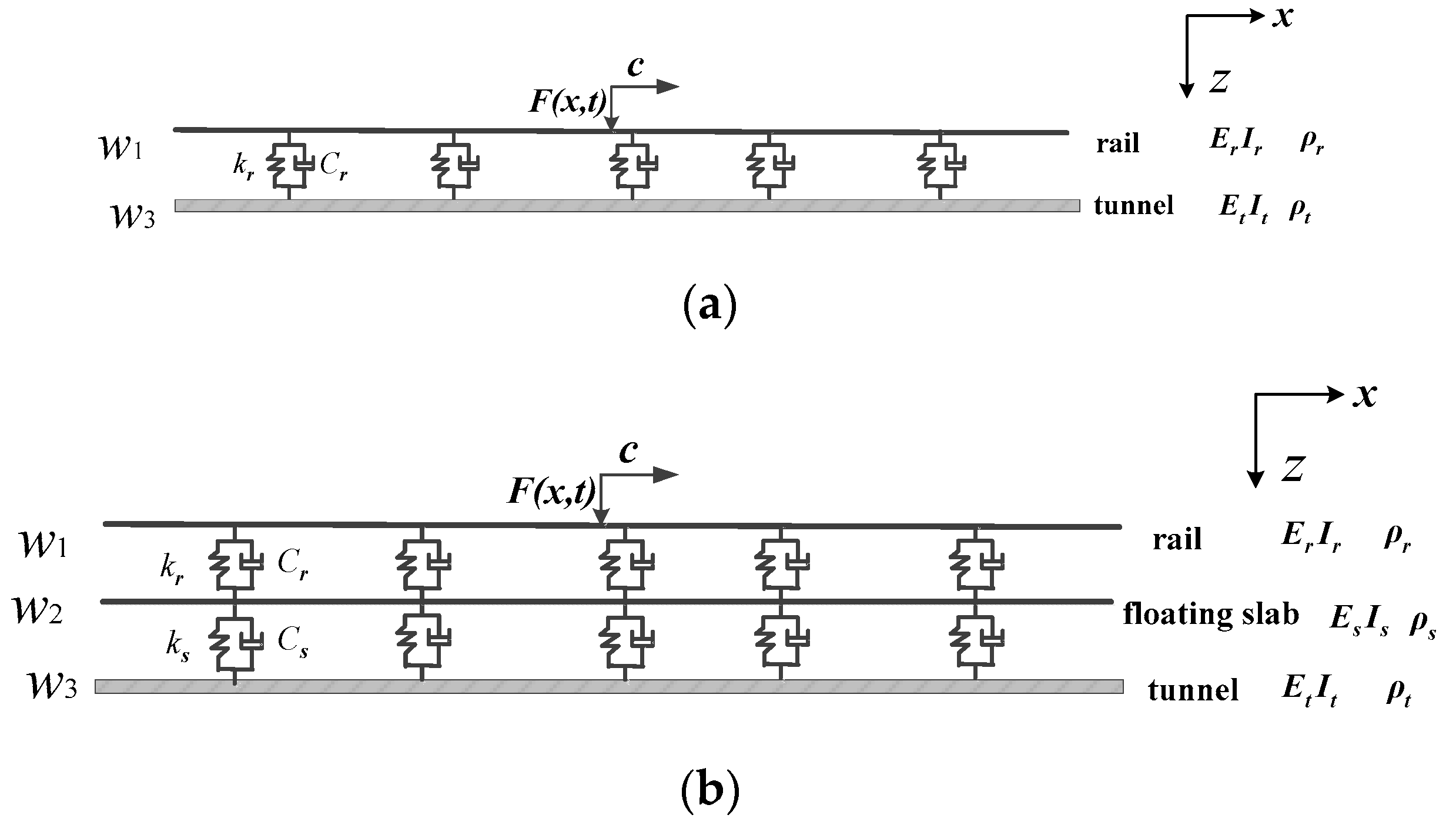
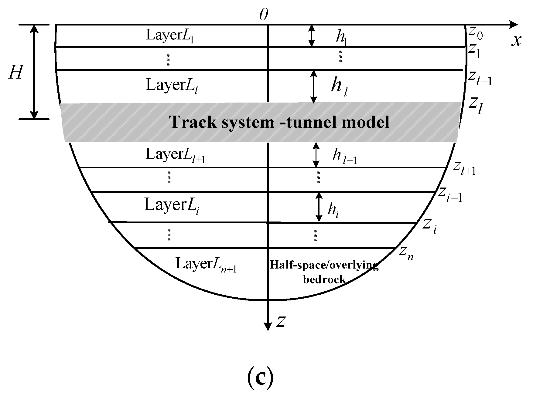
2. Formulation Model of FT/FST System–Tunnel-Layered Saturated Soil

In this paper, the track bed and tunnel were treated as a whole, which is simulated by an infinite Euler–Bernoulli beam with bending stiffnesses E t I t and density ρ t as shown in Figure 1a,b. In the track system, the rail and floating slab were simulated by another two infinite Euler–Bernoulli beams with different bending stiffnesses ( E r I r , E s I s ) and densities ( ρ r , ρ s ). A series of continuous spring-dampers were adopted to simulate the rail support and vibration isolators under the floating slab. The vertical displacement of the rail, floating slab and tunnel are denoted by w 1 , w 2 , and w 3 . The vertical moving point load acting on the rail is represented by F with the expression F ( x , t ) = p e i ω 0 t δ ( x c t ) , in which p is the load amplitude, c and ω 0 are the moving speed and frequency of the load and δ denotes the Dirac function. The ground is modeled as a n + 1 horizontal layer saturated half-space with a free and pervious surface as shown in Figure 1c. The track system and tunnel are embedded in the ground at a depth of H , which is the position of the interface between the l th layer and the l + 1 th layer. The displacement and stress in the soil skeleton and pore water are assumed to be continuous at the interfaces of two adjacent soil layers.
As depicted in Figure 1b, the vibration of rail, slab and tunnel in FST system can be described by the following motion equations:
E r I r 4 w 1 x 4 + ρ r 2 w 1 t 2 + k r ( w 1 w 2 ) + C r ( w 1 w 2 ) t = F ( x , t )
E s I s 4 w 2 x 4 + ρ s 2 w 2 t 2 k r ( w 1 w 2 ) C r ( w 1 w 2 ) t + R t = 0
E t I t 4 w 3 x 4 + ρ t 2 w 3 t 2 = R ( t ) + a ( σ z z ( x , h 0 , t ) σ z z ( x , h + 0 , t ) )
where k r , C r denote the elastic stiffness and the damping coefficient of rail fastener and rail pad, respectively; k s , C s denote the elastic stiffness and the damping coefficient of flexible support of the floating slab, respectively; a represents the characteristic length; R ( t ) denotes the interaction force between the track system and the tunnel with R t = k s ( w 2 w 3 ) + C s ( w 2 w 3 ) t ; σ z z ( x , H 0 , t ) represents the contact stress on the interface between the tunnel and the upper soil; and σ z z ( x , H + 0 , t ) represents the contact stress on the interface between the tunnel and the lower soil.
Similarly, the vibration of the rail and tunnel in the FT system in Figure 1a can be described by the following motion equations:
E r I r 4 w 1 x 4 + ρ r 2 w 1 t 2 + R ( t ) = F ( x , t )
E t I t 4 w 3 x 4 + ρ t 2 w 3 t 2 = R ( t ) + a ( σ z z ( x , h 0 , t ) σ z z ( x , h + 0 , t ) )
where R t = k r ( w 1 w 3 ) + C r ( w 1 w 3 ) t .
The ground soil is regarded as a Biot’s poroelastic medium and the constitutive equations are expressed as follows [33]:
σ i j = λ δ i j θ + μ ( u i , j + u j , i ) α δ i j p
p = α M θ M w i , i
where σ i j is the total stress of the soil; p is the pore water pressure; θ = u i , i is the bulk strain of the solid skeleton; u i and w i denote the displacement of the soil skeleton and the fluid displacement relative to the soil skeleton in i -direction, respectively, i = x , z ; the subscripts (   ) , i denote spatial derivatives; and δ i j is the Kronecker delta.
The boundary and continuity conditions of the track system–tunnel-layered saturated soil model in Figure 1c can be expressed as follows:
On the ground surface, i.e., z = 0 ,
σ x z ( x , 0 ) = 0
σ z z ( x , 0 ) = 0
p ( x , 0 ) = 0
On the interface between two adjacent layers, i.e., z = z i i = 1 , 2 , , n 1 ,
u x ( i ) ( x , z i ) u x ( i + 1 ) ( x , z i ) = 0
w z ( i ) ( x , z i ) w z ( i + 1 ) ( x , z i ) = 0
u z ( i ) ( x , z i ) u z ( i + 1 ) ( x , z i ) = 0
p ( i ) ( x , z i ) p ( i + 1 ) ( x , z i ) = 0
σ x z ( i ) ( x , z j ) σ x z ( i + 1 ) ( x , z i ) = 0
σ z z ( i ) ( x , z i ) σ z z ( i + 1 ) ( x , z i ) = R ( t ) ( ρ B 2 w 3 t 2 + E t I t 4 w 3 t 4 ) u z ( i ) ( x , z i ) = u z ( i + 1 ) ( x , z i ) = w 3 ( x , t )
σ z z ( i ) ( x , z i ) σ z z ( i + 1 ) ( x , z i ) = 0
In addition, when the bottom layer is a half-plane, the positive exponential term in the dynamic response solutions of the layer should be removed because the dynamic response of the soil decays to zero at infinite distance.
When the n + 1 th layer is considered as rigid bedrock, the boundary conditions are given as follows:
u x ( n ) ( x , z n ) = 0
u z ( n ) ( x , z n ) = 0
w z ( n ) ( x , z n ) = 0

3. Solutions for the FST/FT Track System–Tunnel-Layered Saturated Soil Model

3.1. Dynamic Governing Equations of the Saturated Soil

The Biot’s saturated poroelastic medium is governed by the following wave equations [19]:
μ u i , j j + ( λ + α 2 M + μ ) u j , j i + α M w j , j i = ρ u ¨ i + ρ f w ¨ i
α M u j , j i + M w j , j i = ρ f u ¨ i + m w ¨ i + b w ˙ i
where u ˙ ( w ˙ ) , u ¨ ( w ¨ ) denote the first derivative and second derivative of the displacement with respect to time t ; λ and μ are the Lamé constant; α and M are the Biot constants; ρ = n ρ f + ( 1 n ) ρ s , n is the porosity of soil, ρ s and ρ f denote the density of soil skeleton and pore water, respectively; m = ρ f / n ; b is a parameter related to the soil permeability.
Using the Helmholtz decomposition, the displacements u i and w i can be expressed as:
u i = g r a d ϕ 1 + c u r l φ
w i = g r a d ϕ 2 + c u r l Φ
where ϕ 1 , 2 , φ , and Φ denote the potential functions of waves in the soil.
The Fourier transform and inverse Fourier transform with respect to time t and horizontal coordinate x are defined as:
f ¯ ^ ( ξ , z , ω ) = f ( x , z , t ) e i ξ x e i ω t d x d t
f ( x , z , t ) = 1 ( 2 π ) 2 f ¯ ^ ( ξ , z , ω ) e i ξ x e i ω t d ξ d ω
By substituting the potentials into Equation (6a,b) and performing the double Fourier transformation in Equation (8a) to Equation (6), the dynamic response of the poroelastic soil medium in wave number–frequency domain can be obtained:
{ i u ¯ ^ x     u ¯ ^ z     w ¯ ^ z     i σ ¯ ^ x z     σ ¯ ^ z z     p ¯ ^ } T = { J ( z ) } { A       B       C       D       E       F } T
where A ( ξ , ω ) , B ( ξ , ω ) , C ( ξ , ω ) , E ( ξ , ω ) , D ( ξ , ω ) and F ( ξ , ω ) are the undetermined constants and { J ( z ) } =
ξ   e r 1 z                     ξ   e r 1 z                   ξ   e r 2 z                     ξ   e r 2 z                           i r 3   e r 3 z                                       i r 3   e r 3 z r 1   e r 1 z                         r 1   e r 1 z                       r 2   e r 2 z                       r 2   e r 2 z                               i ξ   e r 3 z                                               i ξ   e r 3 z r 1   χ 1   e r 1 z                 r 1   χ 1   e r 1 z               r 2   χ 2   e r 2 z                 r 2   χ 2   e r 2 z                   i ξ   χ 3   e r 3 z                           i ξ   χ 3   e r 3 z 2 μ   ξ   r 1   e r 1 z     2 μ   ξ   r 1   e r 1 z     2 μ   ξ   r 2   e r 2 z       2 μ   ξ   r 2   e r 2 z                   i   a 3   e r 3 z                             i   a 3   e r 3 z   c 1   e r 1 z                               c 1   e r 1 z                                 c 2   e r 2 z                               c 2   e r 2 z                                 2   i μ   ξ   r 3   e r 3 z               2   i μ   ξ   r 3   e r 3 z a 1   e r 1 z                             a 1   e r 1 z                               a 2   e r 2 z                                       a 2   e r 2 z                                             0                                                                   0
where χ i = ( λ + 2 μ ) L i 2 + ρ ω 2 α ρ f ω 2 ρ f ω 2 + α m ω 2 α b ω i     ( i = 1 , 2 ) ; χ 3 = ρ f ω 2 i b ω m ω 2 ; a i = ( α + χ i ) M L i 2   ( i = 1 , 2 ) ; a 3 = μ ( ξ 2 + r 3 2 ) ; c i = 2 μ r i 2 λ L i 2 α a i   ( i = 1 , 2 ) ; r i = ξ 2 L i 2   ( i = 1 , 2 ) ; r 3 = ξ 2 S 2 ; L 1 2 = β 1 + β 1 2 4 β 2 2 ; L 2 2 = β 1 β 1 2 4 β 2 2 ; S 2 = ( ρ f χ 3 + ρ ) ω 2 μ ; β 1 = ( m ω 2 i b ω ) ( λ + α 2 M + 2 μ ) + ρ ω 2 M 2 α ρ f ω 2 M ( λ + 2 μ ) M ; and β 2 = ( m ω 2 i b ω ) ρ ω 2 ρ f 2 ω 4 ( λ + 2 μ ) M .

3.2. Development of the TRM Method

The expressions for the dynamic response of the i th layer in layered ground as given in Equation (11a) can be decomposed as seen in Equation (11b):
ψ ( i ) ( ξ , ω , z ) 6 × 1 = [ i u ¯ ^ x ( i )       u ¯ ^ z ( i )       w ¯ ^ z ( i )   i σ ¯ ^ x z ( i )     σ ¯ ^ z z ( i )     p ¯ ^ ( i ) ] T
ψ ( i ) ( ξ , ω , z ) 6 × 1 = D d ( i ) ( ξ , ω ) D u ( i ) ( ξ , ω ) S d ( i ) ( ξ , ω ) S u ( i ) ( ξ , ω ) × W d ( i ) ( ξ , ω , z ) T W u ( i ) ( ξ , ω , z ) T T
W d ( i ) ( ξ , ω , z ) 3 × 1 = [ B ( i ) e γ 1 ( i ) ( z z i 1 )   D ( i ) e γ 2 ( i ) ( z z i 1 )   F ( i ) e γ 3 ( i ) ( z z i 1 ) ] T  
W u ( i ) ( ξ , ω , z ) 3 × 1 = [ A ( i ) e γ 1 ( i ) ( z i - z )   C ( i ) e γ 2 ( i ) ( z i - z )   E ( i ) e γ 3 ( i ) ( z i - z ) ] T  
where W d ( i ) ( ξ , ω , z ) , W u ( i ) ( ξ , ω , z ) are defined as the down-going and up-going wave vectors in the i th soil layer, respectively.
To simulate wave propagation in the layered soil, the up-going and down-going wave vectors of each soil layer and the transmission and reflection matrices were obtained according to the boundary and continuity conditions of the tunnel-layered soil model in Equations (3) and (4). Thus, the dynamic response of arbitrary soil layer ( 0 < i n + 1 ) in the transformed domain can also be derived. Since the development of the TRM method has been previously reported [25,26,27,28,29], the details will not be described here to avoid repetition.

3.3. Coupling of Track System with the Tunnel-Layered Saturated Soil Model

3.3.1. Solutions for the Dynamic Response of the FST System–Tunnel-Layered Saturated Soil Model

The function G ( ξ , ω , z ) is defined to represent the frequency response function of the layered saturated ground with a tunnel, which includes displacement, stress and pore water responses of the soil in the transformed domain when a moving unit point load exerts on the tunnel [23,24,25].
According to the continuous condition of displacement between tunnel and soil ( z = H ), the vertical displacement of the tunnel w ¯ ^ 3 can be expressed as:
w ¯ ^ 3 = u ¯ ^ z ( ξ , ω , H ) = G ( ξ , ω , H ) u ¯ ^ z R ¯ ^
in which R ¯ ^ denotes the force of the track system acting on the tunnel in frequency–wave number domain, i.e., R ¯ ^ = ( k s + i ω C s ) ( w ¯ ^ 2 w ¯ ^ 3 ) .
Substituting R ¯ ^ into Equation (12), the following expression can be obtained:
R ¯ ^ = k s + i ω C s 1 + ( k s + i ω C s ) G ( ξ , ω , H ) u ¯ ^ z w ¯ ^ 2
Applying the Fourier transform to the motion equations of the rail and floating slab in Equation (2a,b), and substituting Equation (13) into them, the following equations can be obtained:
B 1 - B 2 - B 2 B 3 ( 1 + B 4 G ( ξ , ω , H ) u ¯ ^ z ) + B 4 1 + B 4 G ( ξ , ω , H ) u ¯ ^ z w ¯ ^ 1 w ¯ ^ 2 = F ¯ ^ ( ξ , ω ) 0
where B 1 = E r I r ξ 4 ρ r ω 2 + k r + C r i ω ; B 2 = k r + C r i ω ; B 3 = E s I s ξ 4 ρ s ω 2 + k r + C r i ω ; and B 4 = k s + i ω C s .
By solving Equation (14), all vertical displacement components in the track system and tunnel can be derived by the soil displacement frequency response function G ( ξ , ω , H ) u ¯ ^ z :
w ¯ ^ 1 = B 3 ( 1 + B 4 G ( ξ , ω , H ) u ¯ ^ z ) + B 4 B 5 F ¯ ^ ( ξ , ω )
w ¯ ^ 2 = B 2 ( 1 + B 4 G ( ξ , ω , H ) u ¯ ^ z ) B 5 F ¯ ^ ( ξ , ω )
w ¯ ^ 3 = B 2 B 4 G ( ξ , ω , H ) u ¯ ^ z B 5 F ¯ ^ ( ξ , ω )
R ¯ ^ = B 2 B 4 B 5 F ¯ ^ ( ξ , ω )
where B 5 = ( B 1 B 3 - B 2 2 ) ( 1 + B 4 G ( ξ , ω , H ) u ¯ ^ z ) + B 1 B 4 .
The dynamic response of FST system–tunnel-layered saturated soil model can be obtained after using the double Fourier inverse transform:
w 1 = 1 ( 2 π ) 2 B 3 ( 1 + B 4 G ( ξ , ω , H ) u ¯ ^ z ) + B 4 B 5 F ¯ ^ ( ξ , ω ) e i ξ x e i ω t d ξ d ω
w 2 = 1 ( 2 π ) 2 B 2 ( 1 + B 4 G ( ξ , ω , H ) u ¯ ^ z ) B 5 F ¯ ^ ( ξ , ω ) e i ξ x e i ω t d ξ d ω
w 3 = 1 ( 2 π ) 2 B 2 B 4 G ( ξ , ω , H ) u ¯ ^ z ) B 5 F ¯ ^ ( ξ , ω ) e i ξ x e i ω t d ξ d ω
ψ ( i ) ( ξ , ω , z ) 6 × 1 = G ( ξ , ω , H ) u ¯ ^ z R ¯ ^ = B 2 B 4 G ( ξ , ω , H ) u ¯ ^ z B 5 F ¯ ^ ( ξ , ω )

3.3.2. Solutions for Dynamic Response of the FT System–Tunnel-Layered Saturated Soil Model

Similarly, the FT system can also be coupled with the tunnel-layered saturated soil model via the frequency response function G ( ξ , ω , z ) , and the dynamic response of FT system–tunnel-layered saturated soil model can be derived as the following formula:
w 1 = 1 ( 2 π ) 2 1 + B 2 G ( ξ , ω , H ) u ¯ ^ z ) B 6 F ¯ ^ ( ξ , ω ) e i ξ x e i ω t d ξ d ω
w 3 = 1 ( 2 π ) 2 B 2 G ( ξ , ω , H ) u ¯ ^ z ) B 6 F ¯ ^ ( ξ , ω ) e i ξ x e i ω t d ξ d ω
ψ ( i ) ( ξ , ω , z ) 6 × 1 = G ( ξ , ω , H ) u ¯ ^ z R ¯ ^ = B 2 G ( ξ , ω , H ) u ¯ ^ z B 6 F ¯ ^ ( ξ , ω )
where B 6 = B 1 ( 1 + B 2 G ( ξ , ω , H ) u ¯ ^ z ) - B 2 2 G ( ξ , ω , H ) u ¯ ^ z .

4. Results and Discussion

To investigate the dynamic response of the track system–tunnel-layered saturated soil model, parameter values of the saturated soil and tunnel were chosen and are presented in Table 1 [34]. The amplitude of the moving load is p = 1 0 4 N. The tunnel is embedded in the saturated soil with an overlaying bedrock, the thickness of n soil layers above the bedrock is 27 m ( i = 1 n h i = 27 m) and the tunnel is located at the depth H = 12 m. The parameter values of the track system are listed in Table 2 [16].

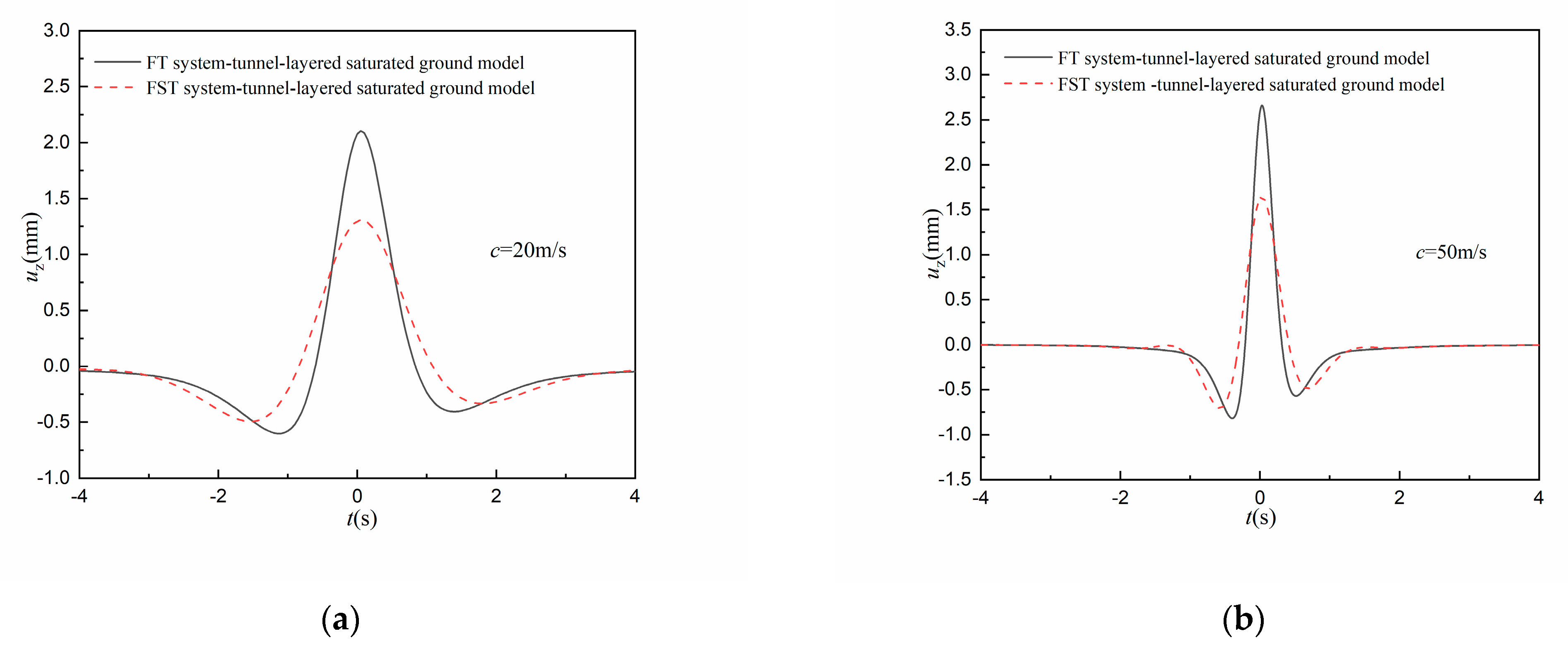
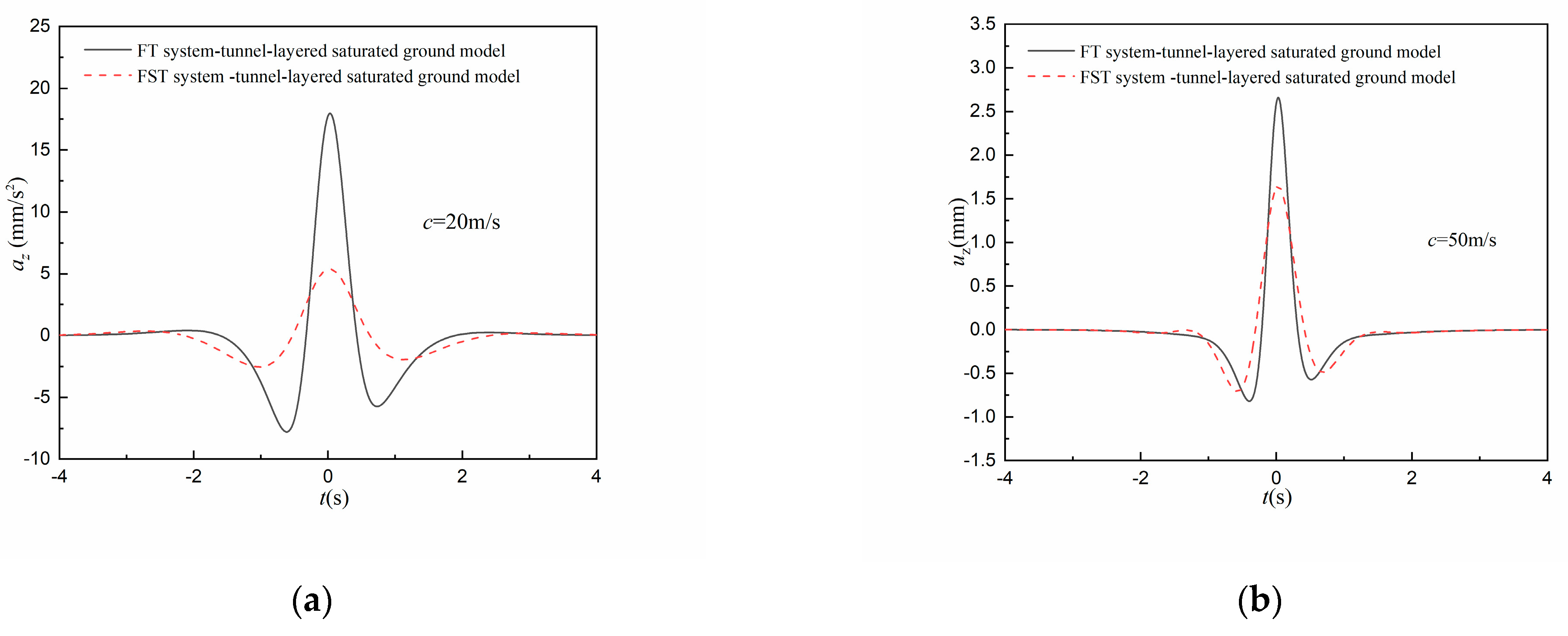
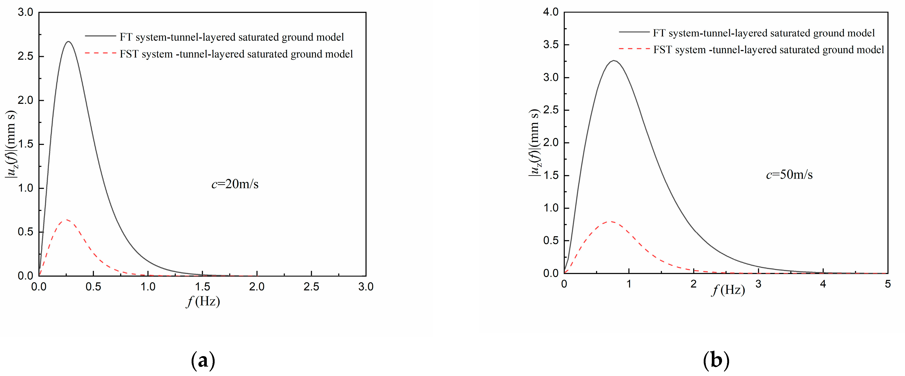
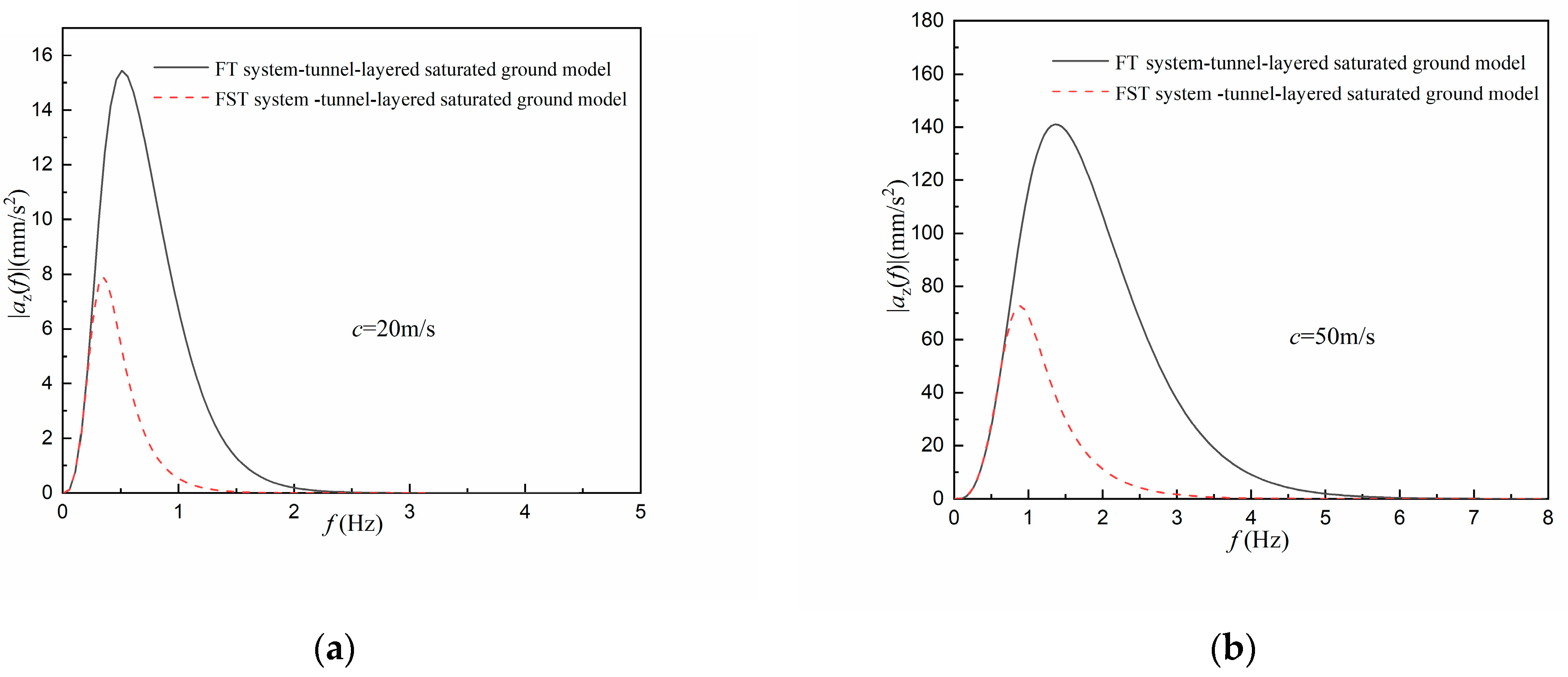
4.1. Surface Vibration under the Constant Moving Load

In Figure 2 and Figure 3, surface vibration of the FT system–tunnel-layered saturated soil model is compared with that of the FST system–tunnel-layered saturated soil model under moving constant loads. It is shown that the vertical displacement increases slightly and acceleration of the ground surface rises almost tenfold when the load velocity increases from 20 m/s to 50 m/s. In addition, the amplitude of vertical displacement as well as the amplitude of vertical acceleration are all reduced by the FST system, and the damping effect on the acceleration is stronger.
The peaks of displacement and acceleration amplitude of the vertical vibration displayed in Figure 4 and Figure 5 increase with the increasing of the load velocity, which is consistent with the results shown in Figure 2, Figure 3 and Figure 4. The frequency spectrum of the vertical acceleration distributes in a wider range than that of the vertical displacement, and the range of the vibration frequency spectrum gets broader when the load velocity increases. It can be observed from Figure 4 that the attenuating effect of the FST system on the soil vertical displacement mainly manifests in the amplitude, and the distribution domain of the vibration spectrum is less affected. All the displacement vibration components in the frequency domain are reduced, and the frequency spectrum of the vibration displacement distributes in a narrower region. The faster the speed of the moving load, the stronger the damping effect of the FST system on the soil vibration amplitude becomes.
In Figure 5, the peak frequencies of the vibration acceleration amplitude are shifted to the left when the FST system is used. It can be observed in Figure 5a that when f > 0.5 Hz, the amplitude of acceleration components obviously decreases, while no obvious attenuation is observed on the amplitude of acceleration components when f < 0.5 Hz. Similarly, in Figure 5b, only the amplitudes of vibration acceleration components in the frequency range f > 1 Hz show obvious reduction. Therefore, the damping effect of the FST system on the amplitude of vibration acceleration mainly manifests on the high-frequency acceleration components.

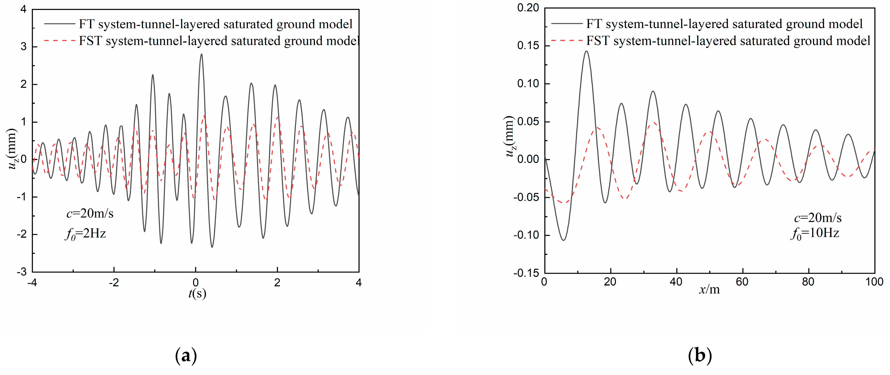
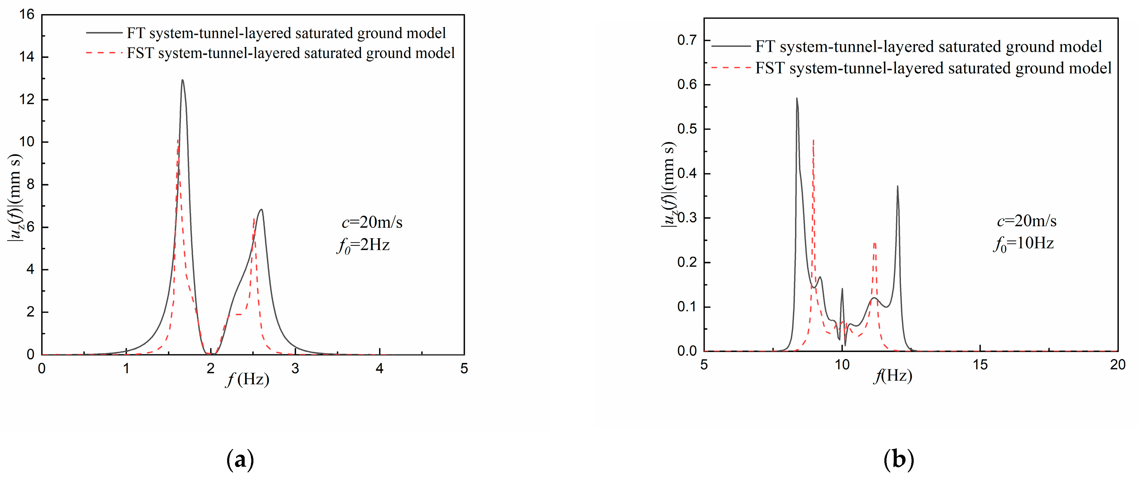
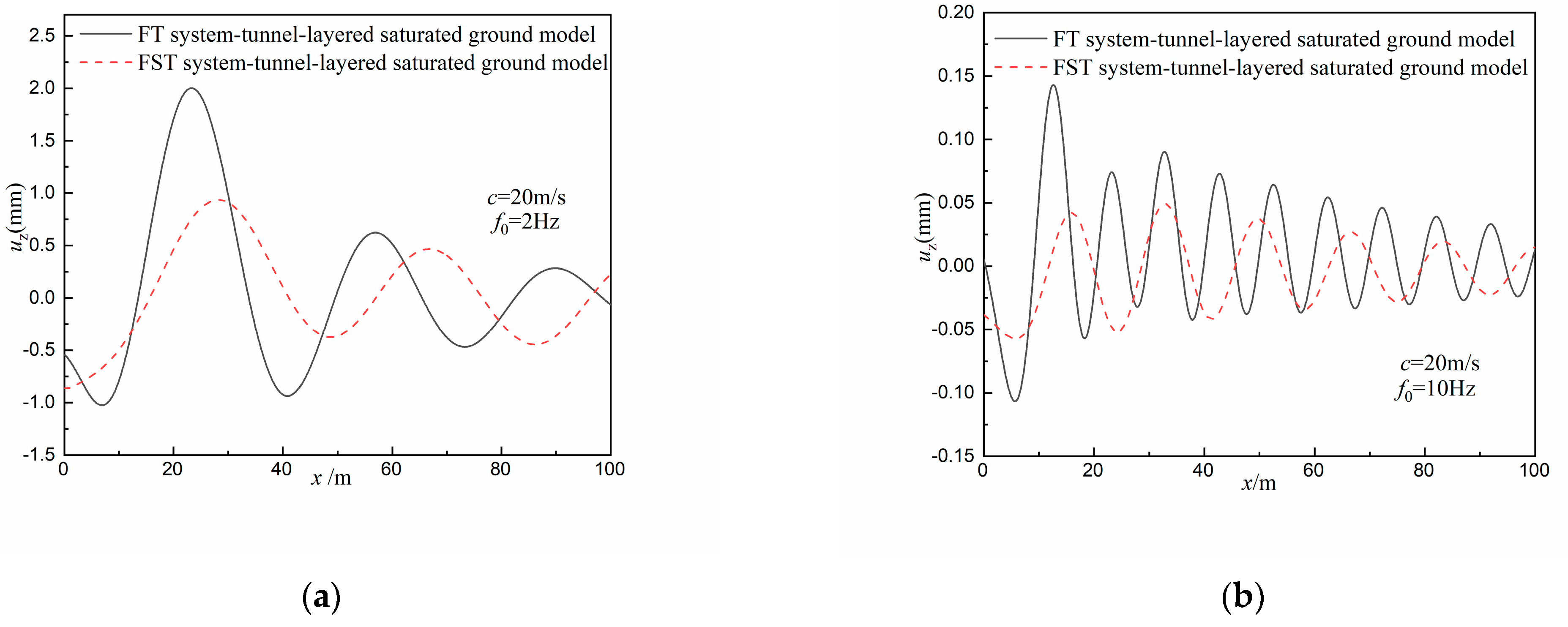
4.2. Surface Vibration under the Harmonic Moving Load

The time history curves and spectrum of the surface displacement under the harmonic moving loads are plotted in Figure 6 and Figure 7, respectively. It can be observed from Figure 6 and Figure 7 that the amplitude of the vertical displacement is reduced with the increase in the load frequency, and that the frequency spectrum concentrates around the load frequency. After the FST system is used, the frequency domain of the vibration spectrum is narrowed and the surface displacement amplitude decreases under the harmonic moving load.
It can be seen in Figure 8 that the wave length of the vibration reduces and the ground vibrates more intensively with the increase in load frequency. Moreover, not only the vibration amplitude but also the vibration frequency are reduced when the FT system is replaced by the FST system.

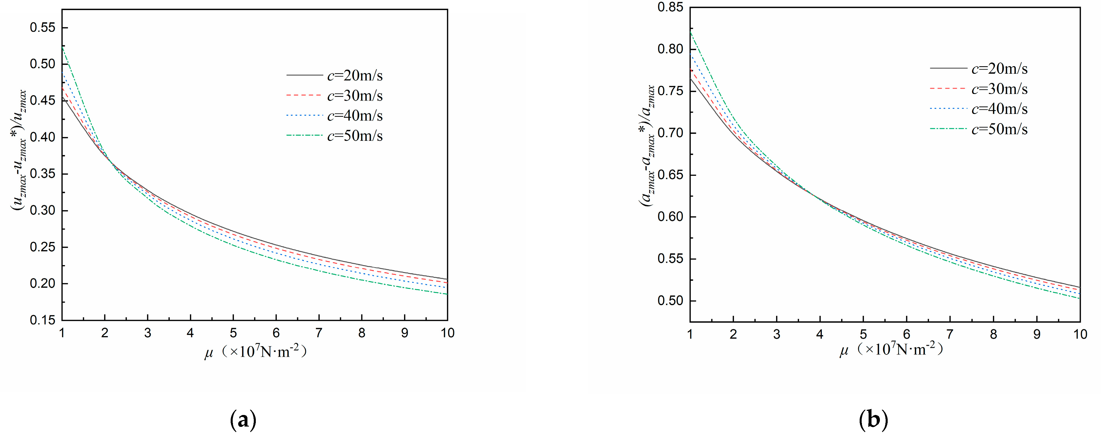
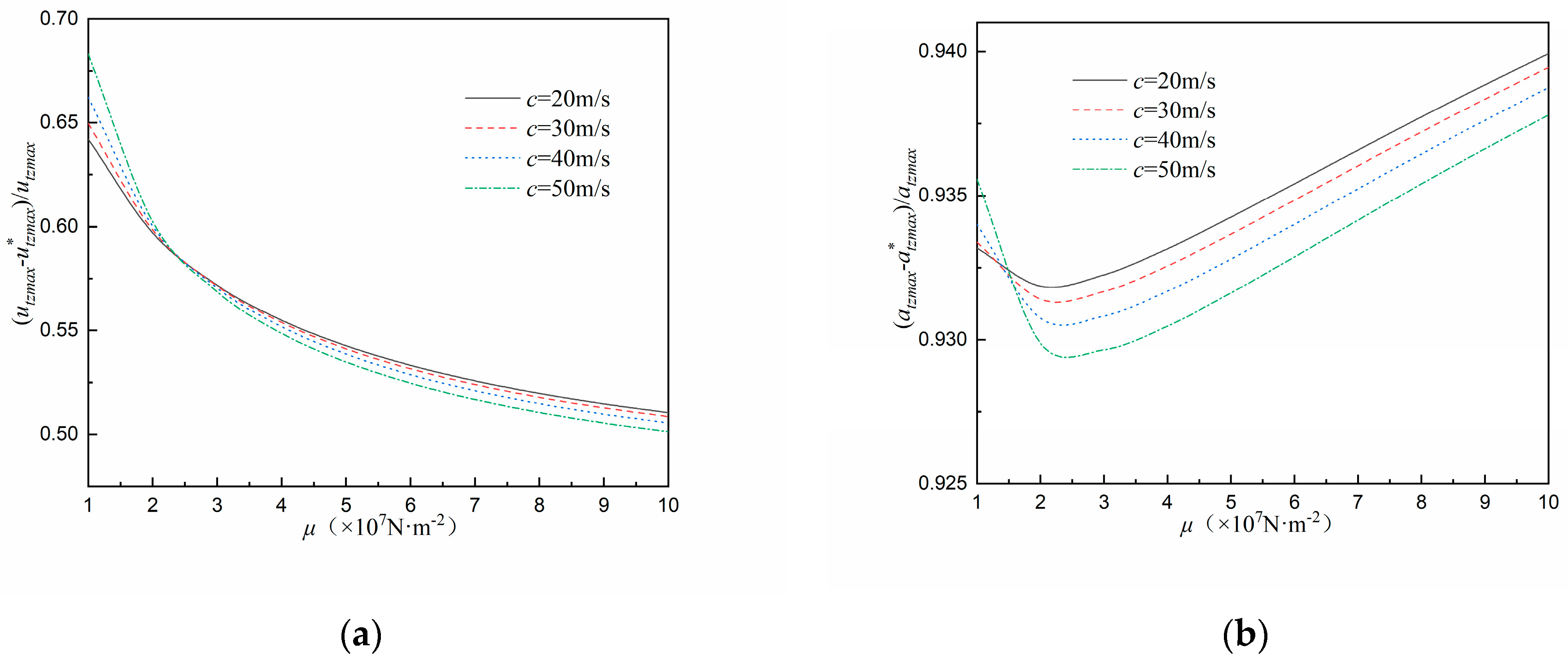
4.3. Effect of Soil Stiffness on Damping Effect of FST System

For the FST system fixed with rigid ground, the vibration isolation effectiveness of the FST system is usually evaluated by the force transmissibility [5,6]. In this paper, considering the dynamic interaction between track system, tunnel and layered saturated soil, two coefficients were defined to evaluate the damping effect of FST system on ground vibration, i.e., u z m a x u z m a x * u z m a x , a z m a x a z m a x * a z m a x , and another two coefficients were defined to evaluate the damping effect of FST system on tunnel vibration, i.e., u z t m a x u z t m a x * u z t m a x , a z t m a x a z t m a x * a z t m a x . The variables with the superscript asterisk “ * ” denote the dynamic response of the FST system–tunnel–saturated soil model, while the variables without the superscript asterisk denote the dynamic response components of the FT system–tunnel–saturated soil model.
Comparing the vertical coordinate value of the curves in Figure 9a,b, the damping effect of the FST system on vibration acceleration is seen to be obviously greater than that on vibration displacement. In addition, with the increase in soil stiffness μ , the damping effect of the FST system decreases and the velocity of the moving load has little influence on the damping coefficients. Comparing Figure 9 and Figure 10, it is shown that the damping effect of the FST system on tunnel vibration is bigger than that on surface vibration, and that the damping effect of the FST system on tunnel vibration varies little with soil stiffness μ .

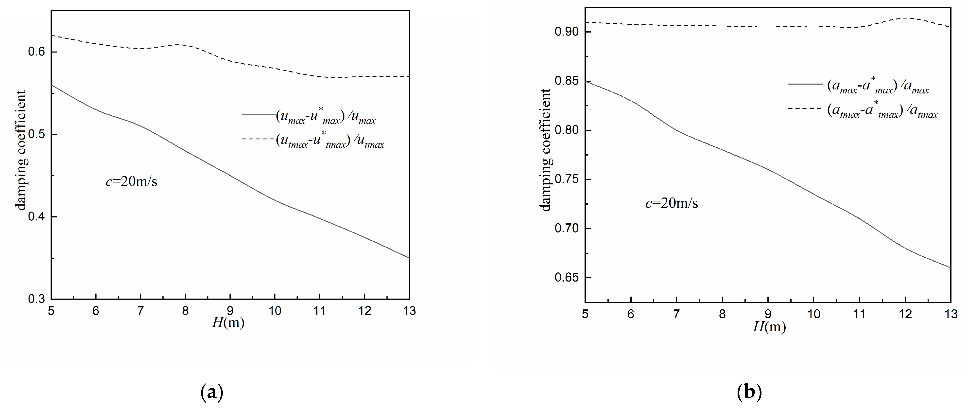
4.4. Effect of Overlaying Soil Layer Thickness on the Damping Effect of FST System

It can be observed in Figure 11 that the damping coefficients of the FST system on tunnel vibration is bigger than that on ground surface vibration, which is consistent with the results shown in Figure 9 and Figure 10. Furthermore, it is shown in Figure 10 that the damping coefficient of the FST system on surface vibration decreases with the increase in the upper soil layer thickness H , whereas the value of the damping coefficient of the FST system on tunnel vibration changes little, which indicates that the damping effect of the FST system on tunnel vibration is less affected by the thickness of the overlaying soil layer.

5. Conclusions

In this paper, the solutions for the dynamic response of the FT system/FST system–tunnel-layered saturated soil model are presented. The time history curves and frequency spectrum for surface vertical vibration in the FST system–tunnel-layered saturated soil model were compared with those of the FT system–tunnel-layered saturated model. In addition, the influences of moving load and soil conditions on the damping effect of the FST system were also investigated by defining four damping coefficients. The following conclusions were obtained:
(1)
Under the constant moving load, the attenuating effect of the FST system on the amplitude of the vibration acceleration is about 30% greater than that on vibration displacement amplitude; the amplitudes of the surface vertical displacement in the whole frequency domain are all attenuated by the FST system, while the attenuation effect of the FST system on the amplitude of the surface vertical acceleration is more obvious in a relatively high-frequency region.
(2)
Under the harmonic moving load, the amplitude of the surface vertical displacement is reduced by the FST system, and the higher the moving load frequency, the more violently the ground vibrates. The vibration displacement amplitude is reduced and the range of vibration frequency spectrum is narrowed after the FST system is used.
(3)
With the increase in the embedded depth of tunnel and the increase in the soil stiffness, the damping effect of the FST system on ground surface vibration recedes, while the damping effect of the FST system on the tunnel vibration is less affected.

Author Contributions

Conceptualization, Y.-J.L. and A.-F.H.; methodology, Y.-J.L.; software, Y.-J.L.; writing—original draft preparation, Y.-J.L.; writing—review and editing, C.L. and Y.-X.M.; supervision, R.-T.Z. and H.X.; project administration, C.L.; funding acquisition, A.-F.H. and C.L. All authors have read and agreed to the published version of the manuscript.

Funding

This research was funded by National Science Foundation of China, grant No. 51978612 and No. 52179110.

Institutional Review Board Statement

Not applicable.

Informed Consent Statement

Not applicable.

Data Availability Statement

The data underlying this paper are available in the paper.

Acknowledgments

This research was also supported by the Ph.D. research startup foundation of Wuhan polytechnical university, grant number 53210052141.

Conflicts of Interest

The authors declare no conflict of interest.

References

  1. Kuo, C.M.; Huang, C.H.; Chen, Y.Y. Vibration characteristics of FST. J. Sound Vib. 2008, 317, 1017–1103. [Google Scholar] [CrossRef]
  2. Li, R.; Chen, K.; Feng, H.; He, L. Research progress on vibration isolation of FST structure of subway. Mech. Sci. Technol. Aerosp. Eng. 2012, 11, 46–52. [Google Scholar]
  3. Hussein, M.F.M.; Hunt, H.E.M. Modelling of floating-slab tracks with continuous slabs under oscillating moving loads. J. Sound Vib. 2006, 297, 37–54. [Google Scholar] [CrossRef]
  4. Cui, F.; Chew, C.H. The effectiveness of FST system—Part I. Receptance methods. Appl. Acoust. 2000, 61, 441–453. [Google Scholar] [CrossRef]
  5. Liu, X.; Wu, C.; Xie, J.; Huang, X. Theoretical analysis of long FST (part I)—Dispersion graph and critical velocity. Chin. J. Comput. Mech. 2009, 26, 919–923. [Google Scholar]
  6. Yuan, J.; Zhu, Y.; Wu, M. Vibration characteristics and effectiveness of floating slab track system. J. Comput. 2009, 4, 1249–1254. [Google Scholar] [CrossRef]
  7. Li, L.-F.; Ma, M.; Liu, W.-N.; Du, L.-L. Analysis for the vibration reduction characteristics of steel spring floating slab tracks under different types of excitation. Eng. Mech. 2018, 35, 253–255. [Google Scholar]
  8. Zhang, S.-Y. Vibration Analysis of Rail Vehicles on Floating Slab Track and Monolithic bed track. Railw. Stand. Des. 2016, 60, 10–13. [Google Scholar]
  9. Liang, R.-H.; Ma, M.; Liu, W.F.; Du, L.L.; Li, L.F. Evaluation of vibration mitigation effect of vibration isolated track considering stratum dynamic characteristics difference. Eng. Mech. 2020, 37, 75–81. [Google Scholar]
  10. Zhou, S.H.; He, C.; Guo, P.; Di, H.; Xiao, J. Three-Dimensional Analytical Model for Coupled Track-Tunnel-Soil System in a Multilayered Half-Space. J. Eng. Mech. 2020, 146, 4019121. [Google Scholar] [CrossRef]
  11. Qiang, H.; Liu, G.; Feng, Q.; Huang, H. Dynamic responses of track-tunnel-ground model induced by moving load. J. Vib. Meas. Diagn. 2020, 40, 8. [Google Scholar]
  12. Forrest, J.A.; Hunt, H.E.M. A three-dimensional tunnel model for calculation of train-induced ground vibration. J. Sound Vib. 2006, 294, 678–705. [Google Scholar] [CrossRef]
  13. Hussein, M.F.M.; Hunt, H.E.M. A numerical model for calculating vibration from a railway tunnel embedded in a full-space. J. Sound Vib. 2007, 305, 401–431. [Google Scholar] [CrossRef]
  14. Bian, X.C.; Jin, W.F.; Jiang, H.G. Ground-borne vibrations due to dynamic loadings from moving trains in subway tunnels. J. Zhejiang Univ. Sci. A Appl. Phys. Eng. 2012, 13, 870–876. [Google Scholar] [CrossRef]
  15. Wei, K.; Zhai, W.; Xiao, J. Influence of track regularity and soil dynamic characteristics on vibration of subway tunnel. J. Southwest Jiaotong Univ. 2013, 48, 989–995. [Google Scholar]
  16. Li, J. Analysis of Effect of the FST on Environmental Vibration. Ph.D. Thesis, Southwest Jiaotong University, Nanjing, China, 2011. [Google Scholar]
  17. Zhou, B.; Xie, X.Y.; Yang, Y.B. Simulation of wave propagation of FST-tunnel-soil system by 2d theoretical model. Int. J. Struct. Stab. Dy. 2013, 14, 1350051-1–1350051-24. [Google Scholar] [CrossRef]
  18. Wu, Z.Z.; Liu, W.N.; Ma, L.X.; Wang, W. Frequency domain analytical method for predicting metro environmental vibration based on soil frequency response function. China Railw. Sci. 2014, 35, 105–112. [Google Scholar]
  19. Hung, H.H.; Chen, G.H.; Yang, Y.B. Effect of railway roughness on soil vibrations due to moving trains by 2.5D finite/infinite element approach. Eng. Struct. 2013, 57, 254–266. [Google Scholar] [CrossRef]
  20. Biot, M.A. Theory of propagation of elastic waves in a fluid-saturated porous solid. Part I: Low-frequency range. J. Acoust. Soc. Am. 1956, 28, 168–178. [Google Scholar] [CrossRef]
  21. Cai, Y.; Sun, H.; Xu, C. Steady state responses of poroelastic half-space soil medium to a moving rectangular load. Int. J. Solids Struct. 2007, 44, 7183–7196. [Google Scholar] [CrossRef]
  22. Yuan, Z.H.; Cao, Z.G.; Boström, A.; Cai, Y.Q. The influence of pore-fluid in the soil on ground vibrations from a tunnel embedded in a layered half-space. J. Sound Vib. 2018, 419, 227–248. [Google Scholar] [CrossRef]
  23. Yuan, Z.-H.; Cai, Y.-Q.; Shi, L.; Sun, H. Response of rail structure and underground tunnel in the saturated soil subjected to a harmonic moving load. Chin. J. Geotech. Eng. 2016, 38, 311–322. [Google Scholar]
  24. Zeng, C. Dynamic Response of Lined Tunnel and Track System in Poroelastic Soil under Subway Load. Ph.D. Thesis, Zhejiang University, Hangzhou, China, 2014. [Google Scholar]
  25. Yuan, Z.H.; Cai, Y.Q.; Zeng, C. Dynamic response analysis of track system and underground railway tunnel in saturated soil subjected to a moving train load. Chin. J. Rock Mech. Eng. 2015, 34, 1470–1479. [Google Scholar]
  26. Di, H.G.; Zhou, S.H.; Luo, Z.; He, C. A vehicle-track-tunnel-soil model for evaluating the dynamic response of a double-line metro tunnel in a poroelastic half-space. Comput. Geotech. 2018, 101, 245–263. [Google Scholar] [CrossRef]
  27. He, C.; Zhou, S.H.; Guo, P.J. Train-Induced Vibrations from a Tunnel in a Layered Half-Space with Varied Groundwater Table. Int. J. Geomech. 2020, 20, 4020174. [Google Scholar] [CrossRef]
  28. Luco, J.E.; Apsel, R.J. On the Green’s functions for a layered half-space. Part I. Bull. Seismol. Soc. Am. 1983, 73, 909–929. [Google Scholar]
  29. Apsel, R.J.; Luco, J.E. On the Green’s functions for a layered half-space. Part II. Bull. Seismol. Soc. Am. 1983, 73, 931–951. [Google Scholar] [CrossRef]
  30. De Barros, F.C.P.; Luco, J.E. Response of a layered viscoelastic half-space to a moving point load. Wave Motion 1994, 19, 189–210. [Google Scholar] [CrossRef]
  31. Lu, J.F.; Hanyga, A. Fundamental solution for a layered porous half space subject to a vertical point force or a point fluid source. Comput. Mech. 2005, 35, 376–391. [Google Scholar] [CrossRef]
  32. Hu, A.F.; Li, Y.; Fu, P.; Sun, B. Dynamic response of the layered saturated foundation-beam coupled system subjected to a buried moving load. J. Vib. Eng. 2018, 31, 140–147. [Google Scholar]
  33. Biot, M.A. Mechanics of deformation and acoustic propagation in porous media. J. Appl. Phys. 1962, 33, 1482–1498. [Google Scholar] [CrossRef]
  34. Yuan, Z.H.; Xu, C.J.; Cai, Y.Q.; Cao, Z. Dynamic response of a tunnel buried in a saturated poroelastic soil layer to a moving point load. Soil Dyn. Earthq. Eng. 2015, 77, 348–359. [Google Scholar] [CrossRef]
Figure 1. (a) FT system–tunnel model; (b) FST system–tunnel model; (c) Track system–tunnel-layered saturated ground coupled model.
Sustainability 15 15495 g001aSustainability 15 15495 g001b
Figure 2. Time history comparison of u z under different moving constant loads. (a) c = 20 m/s; (b) c = 50 m/s.
Sustainability 15 15495 g002
Figure 3. Time history comparison of a z under different moving constant loads. (a) c = 20 m/s; (b) c = 50 m/s.
Sustainability 15 15495 g003
Figure 4. Vertical displacement spectrum of the ground surface under moving constant loads with different velocities. (a) c = 20 m/s; (b) c = 50 m/s.
Sustainability 15 15495 g004
Figure 5. Vertical acceleration spectrum of the ground surface under moving constant loads with different velocities. (a) c = 20 m/s; (b) c = 50 m/s.
Sustainability 15 15495 g005
Figure 6. Time history curves of the vertical displacement under moving harmonic loads. (a) f0 = 2 Hz; (b) f0 = 10 Hz.
Sustainability 15 15495 g006
Figure 7. Vertical displacement spectrum under harmonic moving loads. (a) f0 = 2 Hz; (b) f0 = 10 Hz.
Sustainability 15 15495 g007
Figure 8. Spatial distribution of the surface vertical displacement along the x direction. (a) f0 = 2 Hz; (b) f0 = 10 Hz.
Sustainability 15 15495 g008
Figure 9. Damping coefficients of the FST system on surface vibration versus soil stiffness μ. (a) Vertical displacement of ground surface; (b) vertical acceleration of ground surface.
Sustainability 15 15495 g009
Figure 10. Damping coefficients of the FST system on tunnel vibration versus soil stiffness μ. (a) Vertical displacement of the tunnel; (b) vertical acceleration of the tunnel.
Sustainability 15 15495 g010
Figure 11. Damping coefficients of the FST system on soil vibration versus overlaying soil layer thickness H. (a) Vertical displacement of the soil; (b) vertical acceleration of the soil.
Sustainability 15 15495 g011
Table 1. Parameter values for the saturated soil and tunnel.
Saturated
soil
Lamé constant λ 4.67 × 1 0 7 N⋅m−2Lamé constant μ 2.0 × 1 0 7   N m 2
Porosity n 0.4 Density ρ 1489.6   k g m 3
Biot’s constant α 1.0 Biot’s constant M 6.125 × 1 0 9   N m 2
Internal viscous constant b 1.0 × 1 0 9   kg m 3 s 1
Tunnel Mass   density   ρ t 3 × 1 0 4   kg m 1 Bending   stiffness   E t I t 1 × 1 0 3   MN m 2
Table 2. Parameter values for the track system.
Railway StructureSlab Track Structure
Bending stiffness
E r I r
6.343 × 2 MN m 2 Bending stiffness
E s I s
1430 MN m 2
Mass per unit length
m r
60.34 × 2 kg m 1 Mass per unit length
m s
3500 kg m 1
Stiffness coefficient
k r
100 MN m 1 Stiffness coefficient
k s
12.8 MN m 1
Damping coefficient
C r
50 , 000 Ns m 1 Damping coefficient
C s
35 , 000 Ns m 1
Disclaimer/Publisher’s Note: The statements, opinions and data contained in all publications are solely those of the individual author(s) and contributor(s) and not of MDPI and/or the editor(s). MDPI and/or the editor(s) disclaim responsibility for any injury to people or property resulting from any ideas, methods, instructions or products referred to in the content.

