1. Introduction
To enhance inter-building access, twin towers are often designed with sky-bridges or sky-gardens to connect the two buildings together, such as the Petronas Twin Towers in Kuala Lumpur and Marina Bay Sands Hotel in Singapore. However, these structural links can result in a coupled structural system, and therefore alter the structural dynamic properties [
1]. As a result, the wind-induced responses of the linked twin towers are more complex than a single tower due to their complex aerodynamic characteristics [
2] and structural coupling [
3].
In order to offer a reliable approach for the engineering design of linked twin towers, a wind tunnel test method using simultaneously measured multiple force balances (MFB) was developed by Xie [
4], in which the issues of nonlinear mode shapes [
5] were addressed through instantaneous fitting for the equivalent distribution of fluctuating force. The subsequent investigation using this method indicated that the presence of structural links could result in the redistribution of wind loads between the towers and usually have beneficial impacts on the wind-induced responses [
6]. However, due to the complexity of linked twin towers, achieving a wind-resistant design still remains a technical challenge for twin towers.
For the wind-induced response analysis of linked twin towers, two principal methods are commonly employed: (1) the engineering design method; (2) the theoretical analysis method.
In the engineering design method, a detailed finite element model is established to conduct modal analysis on a specific building using commercial structural analysis software, such as ETABS or SAP2000. Then, based on the aerodynamic forces obtained from wind tunnel tests, the wind-induced responses and equivalent static wind loads [
7] can be calculated. The wind-induced responses acquired using this method are generally highly reliable. However, the results of this method are case-specific and are not suitable for theoretical analysis or general research. The analysis of a large number of different case scenarios to obtain general results is often inefficient. Therefore, the engineering design method is not suitable for guiding the wind-resistant design parameter optimization of linked twin towers.
As a comparison, theoretical analysis methods can provide general results, but simplified analysis models that are suitable for theoretical analysis need to be established. Within the current theoretical methods, twin-tower structures are typically simplified into theoretical models, such as the concentrated mass model [
8], the rigid floor diaphragm model [
9,
10], and the cantilever beam model [
11,
12,
13,
14]. Modal analysis is then performed on the simplified models to obtain the natural frequencies and modal shapes. Based on assumed modal shapes, Lim et al. [
15] proposed a three-dimensional simplified model to analyze the dynamic characteristics of linked twin towers, which investigated the effects of the link’s stiffness on the natural frequencies of the twin towers. While Lim’s model provides a simple formula for the wind-induced response calculation of linked twin towers, its predictions for generalized forces and calculations of wind-induced responses contain some uncertainties due to the overly simplified mode correction coefficients [
16,
17,
18]. To address the limitations of Lim’s model, Song proposed a more comprehensive three-dimensional evaluation model of twin towers which does not require assumed modal shapes, with a rigid floor diaphragm model of the towers and a beam model of each link [
9].
However, there are significant differences between these simplified models and the actual twin-tower structures, especially in terms of the mass and stiffness distribution characteristics, which are difficult to accurately reflect in cantilever beam models. The rigid diaphragm model ignores the axial deformation of columns and the deformation in the plane, so it is only suitable for structural systems in which horizontal displacement between floors dominates. Therefore, while theoretical analysis based on simplified models can reveal general results, its results are not accurate enough for specific engineering projects and are difficult to use in engineering design.
Recently, Kim et al. [
19] studied the optimal location and properties of link bridges using a genetic algorithm based on a three-dimensional analytical model [
20] of twin towers. Arada et al. [
21] conducted an investigation into the impact of the sky-bridge location on linked twin-towers through the application of finite element analyses. Their findings revealed that the inclusion of a sky-bridge effectively mitigated inter-story drift. In a separate study, Zhu et al. [
22] delved into the efficacy of a tuned mass-damper-inerter (TMDI) system in alleviating wind-induced responses within linked twin towers. Their research underscored the capacity of the TMDI system to significantly reduce the acceleration responses of twin towers. Furthermore, Wang et al. [
23] proposed an innovative approach by suggesting the replacement of the solid mass in the TMDI with a liquid mass, introducing the concept of a tuned liquid-column-damper-inerter (TLCDI). Wang’s study introduced an equivalent linearization method to assess the wind-induced responses of twin towers equipped with TLCDIs, ultimately demonstrating a remarkable 37% reduction in wind-induced accelerations achievable through the TLCDI system.
In order to address the limitations of the aforementioned methods, a new method is proposed for guiding the structural link design of twin towers in engineering projects. This method employs a mechanical model based on the actual structure for theoretical analysis, named as the “Modal Substructure method”, or MSS method for brevity. Firstly, the theoretical derivation of the MSS method is presented. Subsequently, the effects of the link properties on the structural dynamic characteristics of twin towers are investigated through parametric analysis. Finally, a case study of 570 m-high twin towers is conducted to verify the accuracy of the MSS method. The primary findings and recommendations are summarized in the conclusion section.
2. Theoretical Derivation of Modal Substructure Method
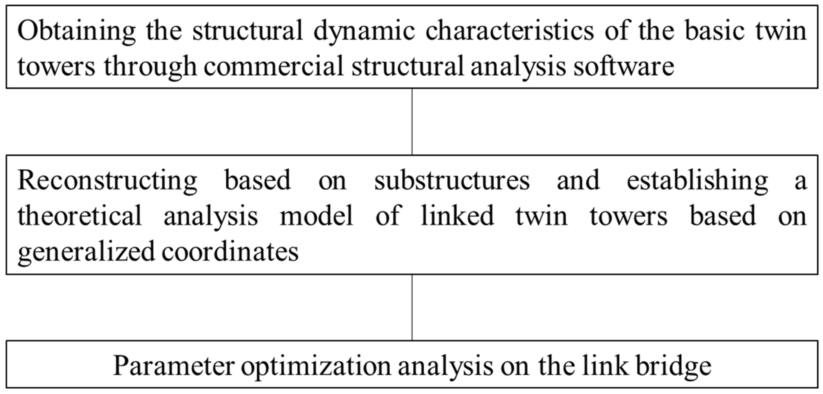
In order to investigate the influence of link bridges on the dynamic characteristics of twin towers, the concept of a substructure is employed to conduct an energy analysis of the two main towers and the link bridges individually. Subsequently, a motion equation for twin towers that reflects the interaction between the substructures is formulated.
The core principle of the MSS method involves initially deriving the structural dynamic properties of the basic twin towers through the utilization of commercial structural analysis software. Based on this, a parameterized theoretical analysis model of the linked twin towers is established. This model serves as the basis for subsequent parameter optimization analysis of the link bridge, with the overarching objective of achieving wind-induced vibration control, as illustrated in
Figure 1.
The model of symmetric twin towers with several link bridges is established, as shown in
Figure 2. According to the energy approach, the displacement vector of each tower is orthogonally decomposed into shape functions (mode shapes) related to geometric coordinates and time-varying functions (mode responses) related to time.
The displacement vector of each tower can be expressed by:
where
is the mode shape of
j-th mode (as shape function),
is the time-varying function of
j-th mode, the subscript T refers to Tower, and the subscript
k represents Tower k.
The total kinetic energy of the two main towers can be expressed by:
where
Mkj is the generalized mass of
j-th mode.
As shown in
Figure 2, assuming that there are n link bridges at various heights
i (
i = 1, 2, ...n), the total displacement of the bridges can be expressed by:
where
represents the average displacement (rigid motion) caused by the displacement of the main towers,
denotes the relative displacement between the towers and the bridges, and the subscript B refers to Bridge.
The constraints on the bridges can be expressed by
, which are related to the stiffness of the bridges and the connection modes of the link bridges and main towers. The stiffness coefficient in the
x direction reflects the axial stiffness of the bridges between the two towers, and the one in the
y direction reflects the lateral bending and shear stiffness of the bridges.
and
represent the damping and mass of the link bridges, as shown in
Figure 3.
In addition to the deformation energy, the potential energy of each tower is also generated by the relative displacement between the bridges and the two towers. Then, the total potential energy of the two towers can be expressed as:
where
is the generalized stiffness of the towers (
),
fj is the natural frequency of
j-th mode, and
represents the relative displacement between the bridges and the twin towers.
If the dampers are installed on the link bridges, the total dissipated energy of the two towers can be expressed as:
where
is the generalized damping of the twin towers (
), and
is the damping of bridge
i.
The kinetic energy of the bridges can be expressed by:
where
denotes the mass of bridge
i.
The potential energy of the bridges depends on the relative displacement, which can be expressed by:
where
is the stiffness of bridge
i.
If the dampers are installed on the link bridges, the dissipated energy of the bridges can be expressed as:
where
is the damping coefficient of bridge
i.
The work performed by the wind loads on the towers can be expressed as:
where
denotes the aerodynamic force vector acting on tower
k.
The work performed by the wind loads on the bridges can be expressed as:
where
is the aerodynamic force vector acting on the bridge
i.
Based on the principle of the Lagrange equation, the equation can be written as:
Substituting Equations (5)~(12) into Equation (13), the motion equations for the tower-bridges system can be written as:
Based on the aforementioned derivations, we have successfully established the equation of motion for the twin towers, which can be applied in the following contexts:
- (1)
The equation is versatile and adaptable to various configurations of twin towers. For instance, when the stiffness and damping of the link bridges are both zero, it represents the scenario of structurally detached twin towers. In cases where the stiffness of the bridges is zero, but the damping is non-zero, it denotes that the twin towers and the bridges are connected by sliding supports with viscous dampers. Conversely, when the stiffness of the bridges is non-zero, but the damping is zero, it signifies that the twin towers and the bridges are in rigid connection or elastic connection without viscous dampers.
- (2)
The equation serves as a valuable tool for the wind-resistant design optimization of twin towers, particularly for evaluating the effect of the bridge mass, stiffness, and damping on the wind-induced responses of the twin towers.
For simplicity, the common symmetric twin towers with only one link bridge are discussed below. Thus, the equation of motion for the twin towers can be simplified as:
The following parameters are introduced as follows:
Substituting the above parameters into Equation (15), the equation of motion can be rewritten in parametric form by:
where
,
.
Then, the Fourier transform is performed on both ends of the above equation to obtain:
As the wind loads acting on the main towers are significantly greater than that on the link bridge, only the transfer of the tower wind loads need to be considered for the tower responses. The transfer function of the twin towers for wind loads can be determined by:
where the derivation process of the transfer function is given in the
Appendix A.
The transfer function of the bridge for the wind loads on towers can be determined by:
The transfer function of the bridge for the local wind loads on the bridge can be determined by:
In comparison, the transfer function of the twin towers without link bridges is given by:
For performance evaluation, the acceleration is normally taken as the indicator, which can be expressed by:
where
is the variance of acceleration, and
is the generalized force spectrum. For tall building structures, the background portion expressed by integration is much smaller than the resonance portion. Therefore, the acceleration can be expressed approximately as:
The relationship between the acceleration and the structural damping ratio, shown in Equation (23), can be used to estimate the effects of the link bridge on the wind-induced acceleration of twin towers. The equivalent damping ratio of the tower-bridge system can be expressed as follows:
where
denotes the acceleration variance of the twin towers with no link bridge;
denotes the acceleration variance of the twin towers with a link bridge;
is the equivalent damping ratio of the linked twin towers.
3. Parametric Study of the Link Bridge by MSS Method
The effects of the link bridge’s parameters (such as the damping ratio, mass, and frequency) on the structural dynamic properties of the towers are investigated, with a generic twin building configuration. The goal of optimization is to maximize the equivalent damping ratio
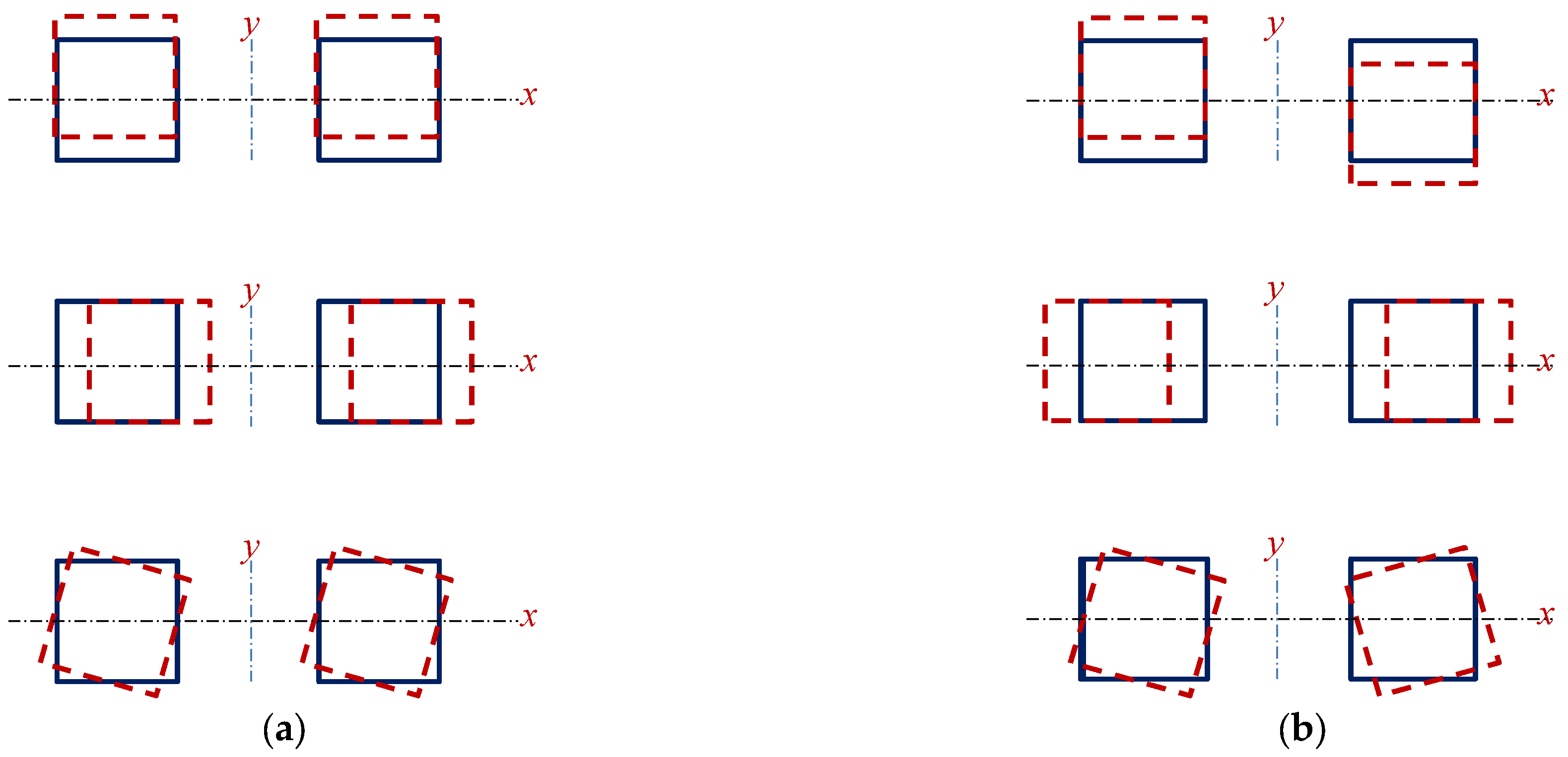
by modifying the link bridge parameters. A typical twin-tower structure consists of two buildings with symmetrical geometrical shapes and structural properties. The most significant modes of vibrations to wind effects can be divided into two categories [
24]: the in-phase modes and the out-of-phase modes, as illustrated in
Figure 4.
3.1. In-Phase Modes
Case 1: the in-phase modes are dominant, as shown in
Figure 4a; the corresponding mode parameters are as follows:
where
denotes the average displacement of the two towers, and
denotes the relative displacement of the two towers.
Substituting Equation (25) into Equation (16), the equations of motion can be simplified as:
The effect of the link bridge on the twin towers, particularly in the context of in-phase modes, reveals three noteworthy aspects:
- (1)
The presence of the link bridge contributes to an increase in the generalized mass of the tower-bridge system. This increase is not solely determined by the bridge’s own mass but is also influenced by the magnitude of the mode displacement, which depends on the bridge position. Notably, higher positions of the link bridge exhibit a more pronounced effect in augmenting the generalized mass.
- (2)
The link bridge has no effect on the stiffness and damping of the tower-bridge system under the in-phase mode. Consequently, there is a marginal reduction in the natural frequency of the tower-bridge system; the estimated reduction ratio can be estimated as
. As Hu’s research [
3] shows, additional link mass decreases the structural frequency of twin towers.
- (3)
The link bridge has the potential to suppress the towers’ motion by exerting counteracting forces on the towers, similar to tuned mass dampers. The motion of the bridge in Equation (26) could be synchronized with the motion of the towers, which can be achieved by adjusting the design parameters of the bridge.
The structural dynamic properties of the link bridge can be determined using three design parameters:
= damping ratio;
= mass ratio;
= frequency ratio.
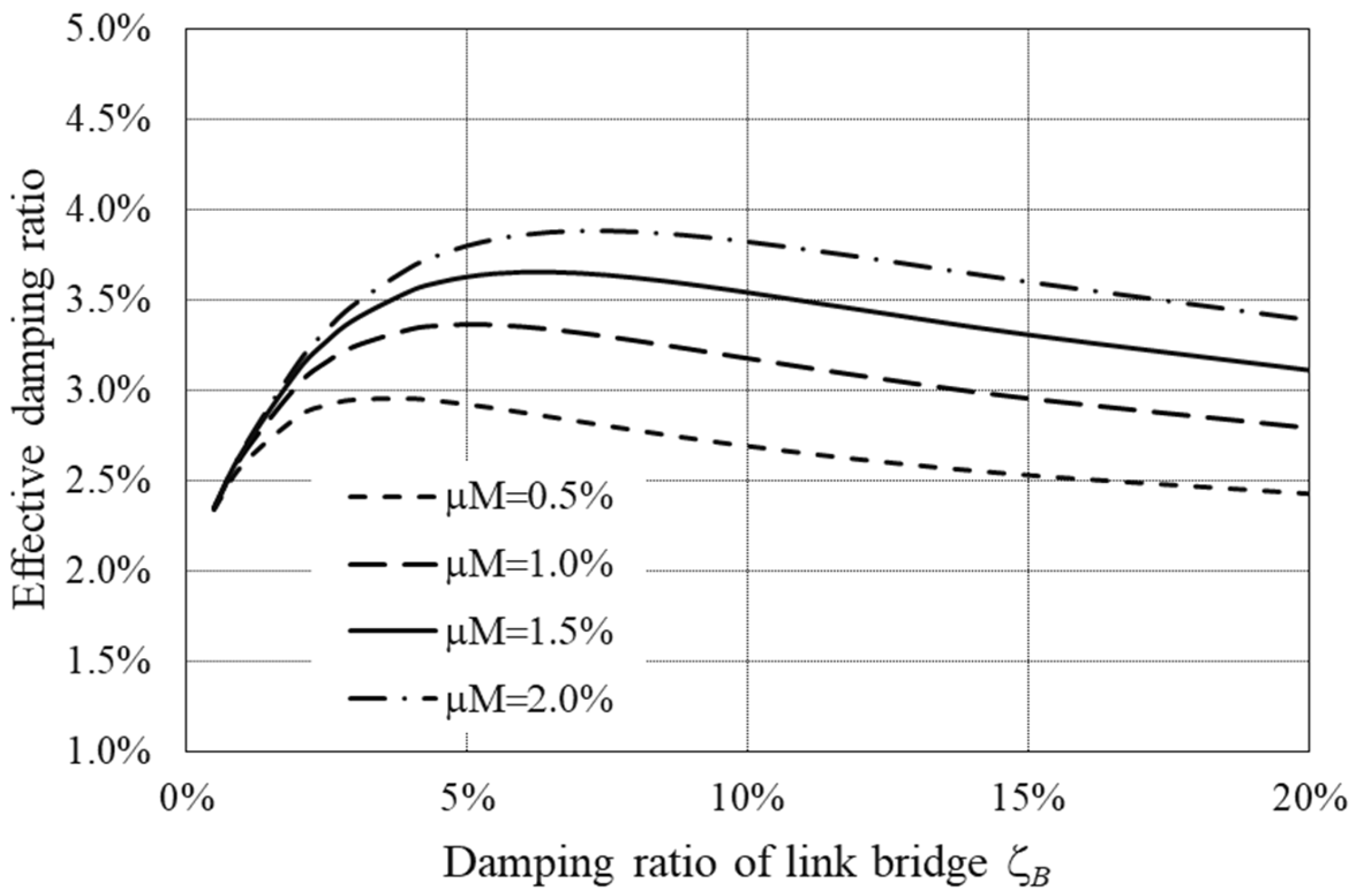
The equivalent damping ratio , defined in Equation (24), is then utilized to optimize the design parameters of the link bridge for achieving wind-induced vibration control. It is assumed that the natural frequency of the bridge is basically the same as that of the main tower, and the original damping ratio of the twin towers is 2%.
Figure 5 shows the equivalent damping ratio of the entire system (twin towers with a link bridge) as a function of the link bridge damping ratio. The equivalent damping ratio exhibits an initial increase, followed by a decrease, as the bridge damping ratio is raised. Furthermore, under the condition of a constant bridge damping ratio, an increase in the mass ratio leads to an augmentation of the equivalent damping ratio. The optimal value of the bridge damping ratio depends on the mass ratio. For a small mass ratio, such as 0.5%, the optimal bridge damping ratio is about 2.5% and the maximum equivalent damping ratio
can reach 3%. If the mass ratio is 2%, the maximum reachable equivalent damping ratio can be 3.9% at the bridge damping ratio of 6%.
Figure 6 shows the equivalent damping ratio as a function of the mass ratio. It indicates that while the equivalent damping ratio tends to increase with a higher mass ratio, its efficiency is significantly influenced by the bridge damping ratio. For instance, when the bridge damping ratio is relatively small, such as only 3%, the increase in the mass ratio from 1% to 8% leads to a minor rise in the equivalent damping ratio from 3.3% to 3.6%. Conversely, with a bridge damping ratio of 10%, the same increase in the mass ratio from 1% to 8% results in a more substantial rise in the equivalent damping ratio, from 3.3% to 5.0%. Furthermore, under the condition of a constant bridge mass ratio, an increase in the bridge damping ratio leads to an augmentation of the equivalent damping ratio.
Figure 7 shows the equivalent damping ratio as a function of the frequency ratio. It shows that in order to use the link bridge to improve the dynamic responses of the twin towers, the natural frequency of the bridge should be the same as the tower frequency. By adjusting the elastic support of the bridge, the frequency of the bridge is made consistent with the frequency of the main tower, thus improving the wind-induced responses of the twin towers. Multiple link bridges could be set when it is necessary to improve the wind-induced responses of multiple in-phase modes. Each bridge could be adjusted to control the corresponding in-phase mode in order to achieve a comprehensive improvement in the wind-induced responses. Therefore, in the in-phase modes, link bridges can serve as tuned mass dampers (TMDs) to attenuate the wind-induced responses of twin towers. The strategic application of out-of-phase forces to the twin towers through the link bridges can result in a substantial reduction in wind-induced responses in the in-phase modes.
3.2. Out-of-Phase Modes
Case 2: the out-of-phase modes are dominant, as shown in
Figure 4b; the corresponding mode parameters are as follows:
Substituting Equation (27) into Equation (16), the equations of motion can be simplified as:
It can be seen that, in the case of the out-of-phase mode, the link bridge affects the twin towers in three ways:
- (1)
The damping and stiffness of the bridge increase the damping and stiffness of the tower-bridge system, but do not change the inertial characteristics of the system.
- (2)
The equivalent damping ratio of the tower-bridge system could be estimated as .
- (3)
The bridge causes the natural frequency of the tower-bridge system to increase, with an increase ratio of approximately .
It can be found that in order to control the wind-induced responses of the out-of-phase modes, the constraint stiffness and damping of the link bridge could be adjusted, thereby increasing the natural frequency and damping ratio of the overall tower-bridge system to achieve the goal of wind-induced vibration control.
It is worth noting that the above analysis of the equivalent damping ratio and structural natural frequency increase brought about by the bridge only applies to cases where the damping and stiffness of the bridge are relatively small. Excessively large damping and stiffness of the bridge will result in the formation of a displacement node at the connection node of the bridge, thus inhibiting the appearance of the out-of-phase mode.
In the in-phase and out-of-phase modes, the link bridge exhibits varying impacts on the structural dynamic characteristics and wind-induced responses of twin towers. As Kim [
19] pointed out, the relationship between the aerodynamic correlation and wind-induced responses is significant. In cases where a positive or negative correlation exists, a notable discrepancy is observed in the reduction in responses in linked twin towers.
4. Validation of MSS Method with Case Study
In the derivation of the Modal Substructure method, two fundamental assumptions are included: (1) The fundamental mode shapes of a single tower can be used as shape functions in the modeling process of the MSS method (referred to as in Equation (1); (2) The torsional aerodynamic forces acting on each tower are insignificant when compared to the horizontal forces, and can therefore be disregarded in the approximate calculation.
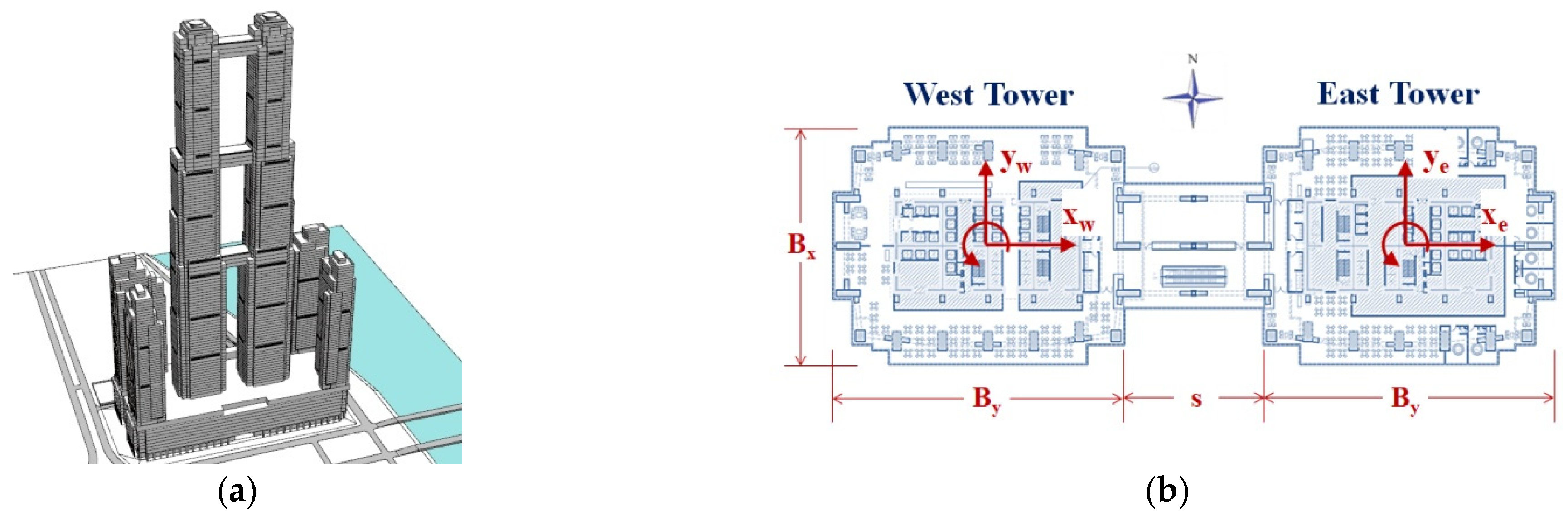
To verify the acceptability of the two assumptions of the MSS method, a case study was conducted based on the World Trade Center (WTC) twin towers in Phnom Penh, as shown in
Figure 8.
The WTC twin towers consists of two 570 m-high linked buildings, surrounded by four residential buildings, each about 220 m high, and a 55 m-high mixed-use podium. The twin towers were designed with three link bridges at different heights, with the floor plan width decreasing progressively from 68 m × 52 m at the podium level to 46 m × 44 m at the top occupied floor.
In order to investigate the sensitivity of the wind-induced responses of twin towers to the presence of a link bridge, two extreme scenarios were considered: Case 1—detached twin towers; Case 2—linked twin towers.
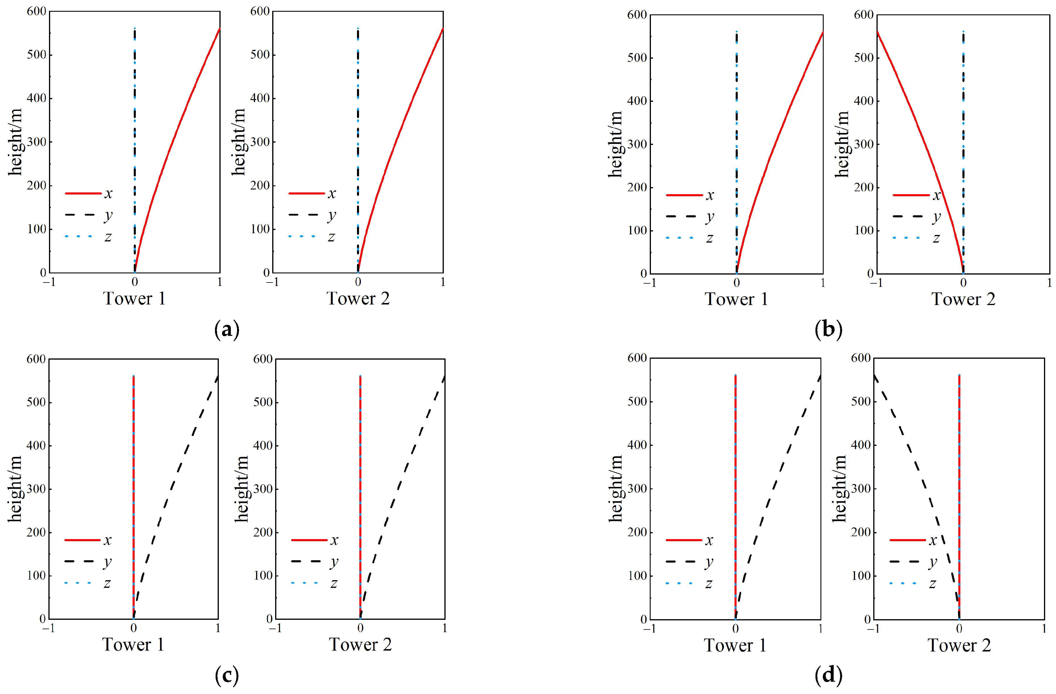
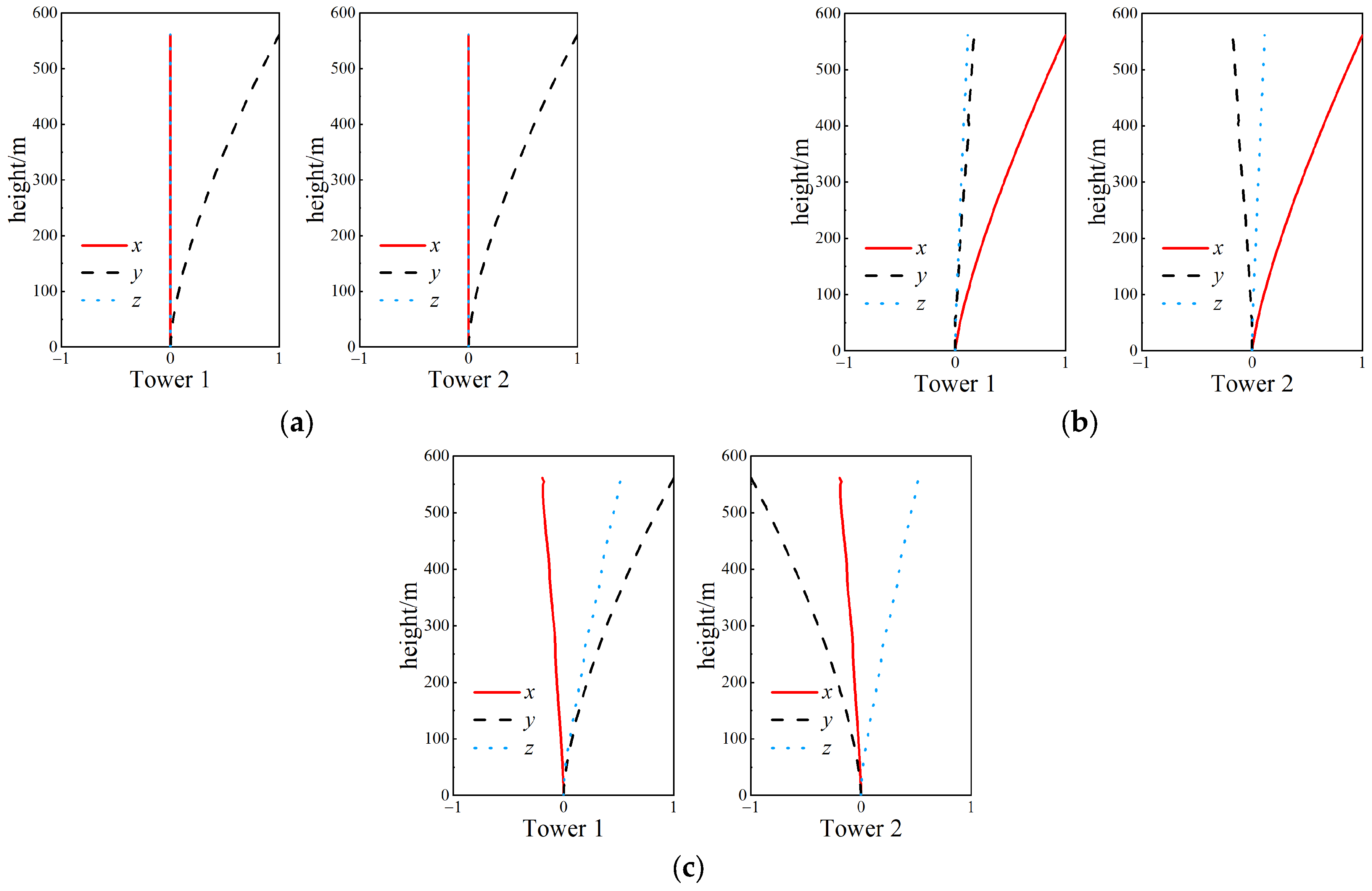
Through detailed finite element analysis for the WTC twin towers, the typical modes were obtained for Case 1 and Case 2, as shown in
Figure 9 and
Figure 10.
It can be seen from
Figure 9 and
Figure 10 that, regarding the fundamental modes, the mode shapes with and without the link bridge were found to be very similar. This indicates that using the basic mode of the single tower as a shape function in MSS modeling is reasonable. The influence of the link bridge on the modes mainly occurs in the higher-order modes, but the wind-induced responses of super-tall buildings are controlled by the responses of the fundamental modes.
4.1. Wind Tunnel Test and Analysis Method
To measure the aerodynamic forces on the twin towers, a multi-force-balance (MFB) method was adopted [
4], which has been successfully applied in engineering practice for many super-tall buildings worldwide.
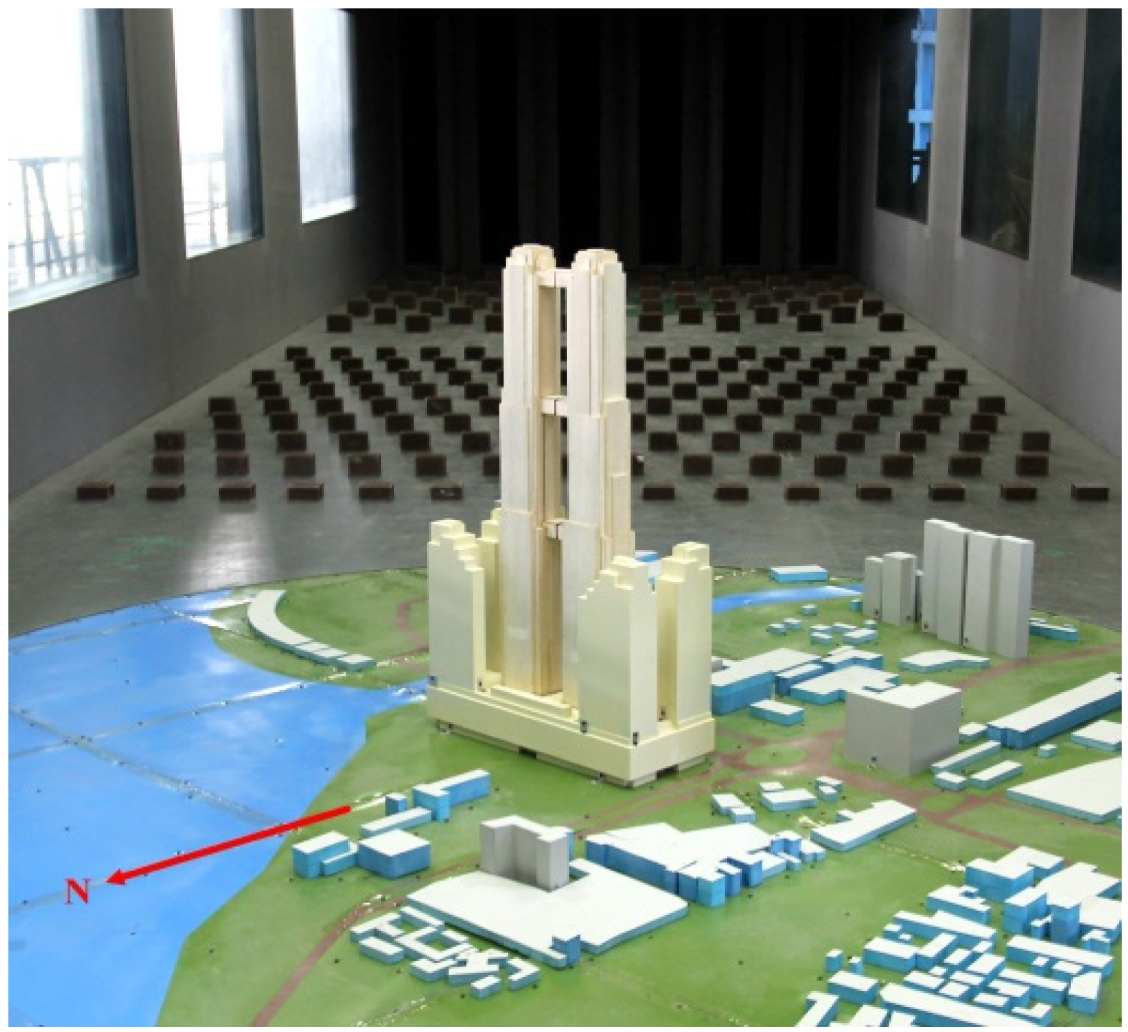
The wind tunnel model was fabricated at a geometric scale of 1:500 and tested in the Boundary Layer Wind Tunnel Laboratory of Zhejiang University, as shown in
Figure 11.
The wind tunnel measurements were carried out for 36 wind directions at 10° intervals, starting from north (0°). For each wind direction, the overall aerodynamic forces of the two towers were recorded simultaneously at a sampling rate of 300 Hz for 90 s, which correspond to about 90 min recording at full scale.
The generalized aerodynamic force can be calculated as below:
where
Fx and
Fy are the base shears in two orthogonal directions,
Mx and
My are the base overturning moments in two orthogonal directions,
Mz is the base torque.
and
are contribution factors as functions of the mode shapes and building properties [
4], and
r is the radius of gyration used for normalizing torsional mode shapes.
Given the generalized force, one can calculate the wind-induced response of twin towers using the structural dynamic characteristic. Firstly, the detailed finite element models are established for the detached twin towers and linked twin towers, respectively; then, the corresponding modal shapes and natural frequencies are obtained using finite element software. Among the current wind-resistant design methods, the wind-induced response (e.g., the wind-induced accelerations and design wind loads) obtained using this method is considered to be the most reliable. For the sake of brevity, the wind-induced response obtained using this method will be referred to as the “accurate” results.
By comparison, the MSS method only adopts the structural dynamic characteristics of detached twin towers, and the corresponding fundamental modes are used as the shape functions in the modeling using the MSS method. The wind-induced response of the linked twin towers calculated using the MSS method is approximate, but it is convenient to investigate the effects of the link properties on the wind-induced responses of twin towers. For the sake of brevity, the results obtained using this method will be referred to as the “MSS” results.
4.2. Characteristics of Generalized Forces
The generalized forces
GF of each mode were normalized by the reference force as follows:
where
is the air density,
UH is the reference wind speed at the building height,
By and
H are the building width and building height, respectively.
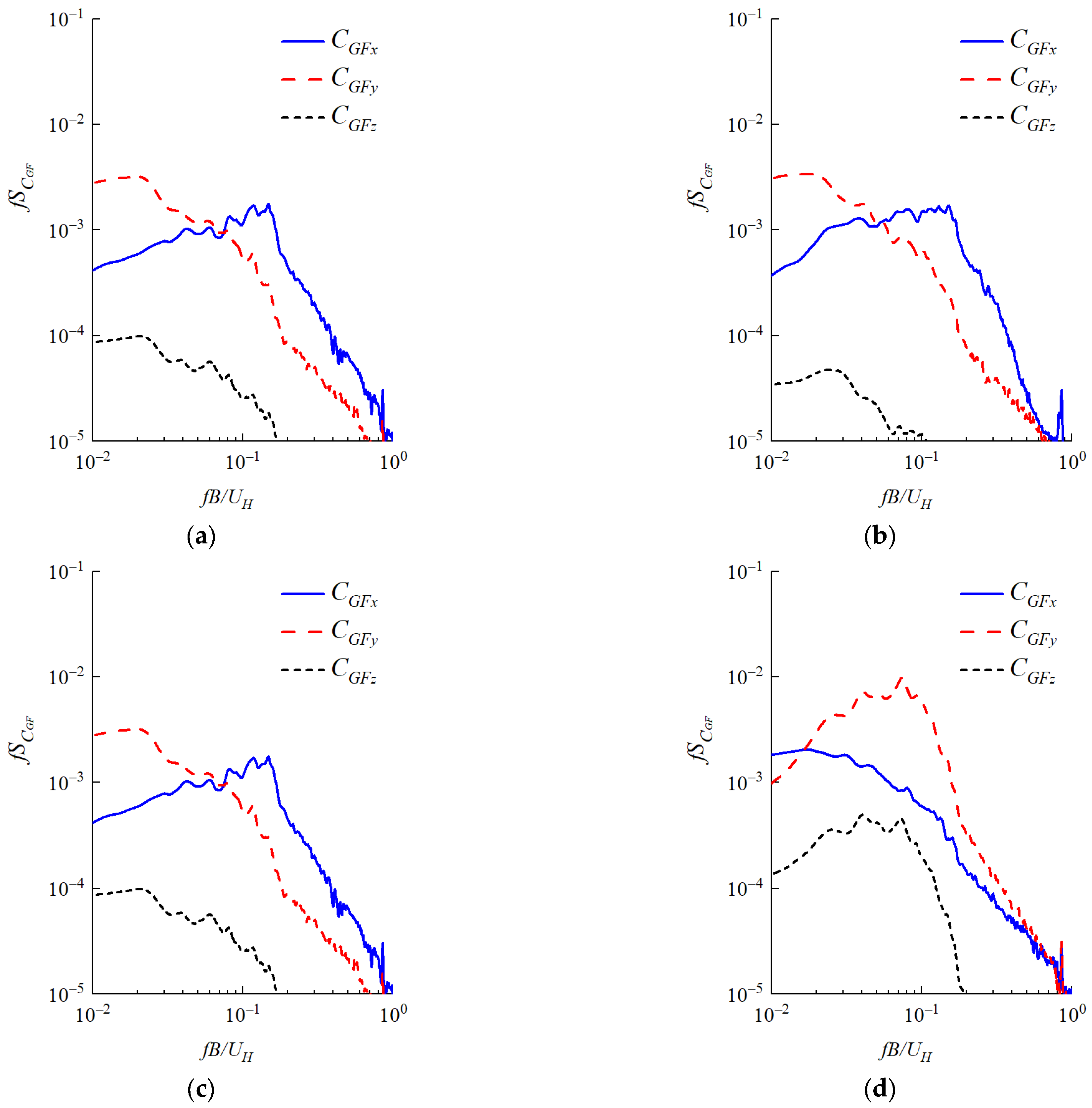
The spectra of the generalized force coefficient of the detached twin towers for the typical wind directions are shown in
Figure 12.
By comparing the power spectra of the generalized force coefficients, it is evident that the torsional aerodynamic forces of each tower are far less than the horizontal forces for the rectangular twin towers. The torsional response of the twin towers is mainly caused by the out-of-phase horizontal aerodynamic forces along the y-direction, while the contribution of the torsional forces on the main tower to the overall torsional response are actually very small. Therefore, the torsional aerodynamic forces on each tower are insignificant compared to the horizontal forces.
4.3. Validation of MSS Method
To validate the accuracy of the wind-induced response results calculated using the MSS method, a case study was conducted based on the WTC twin towers to compare the differences between the “MSS” results and the “accurate” results.
The modal shapes and natural frequencies used in the accurate approach are obtained using the finite element software (refer to
Figure 9 and
Figure 10), while the structural parameters used in the MSS method are given in
Table 1.
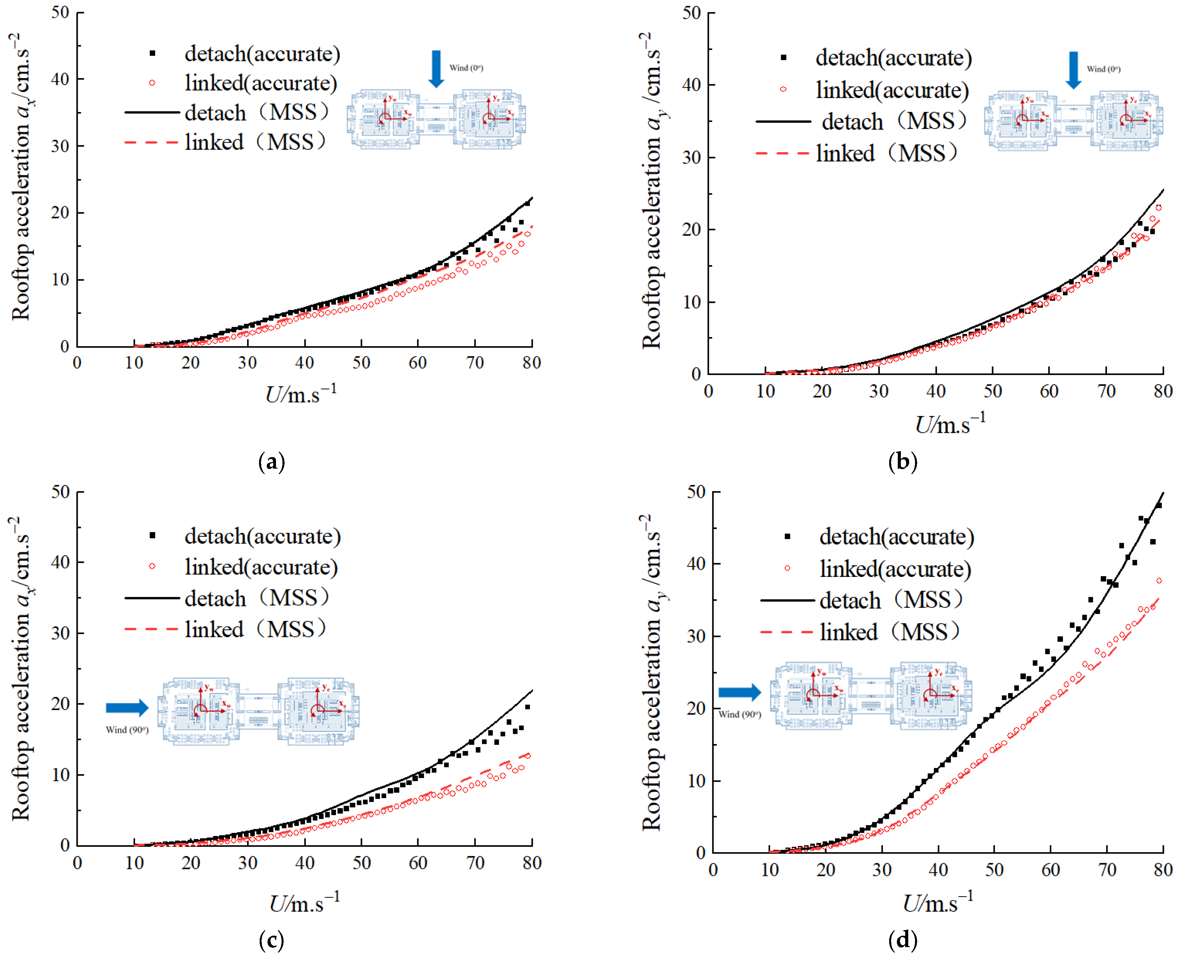
The results of the wind-induced accelerations of the WTC twin towers calculated using the accurate method and MSS method are given in
Figure 13.
It can be seen from
Figure 13 that the wind-induced acceleration results calculated using the MSS method are approximate; however, the MSS results are in very good agreement with the accurate results. When the MSS method is used for the wind resistance design optimization of the linked twin towers, it can avoid a large amount of finite element modeling for different link configurations. Therefore, the MSS method can not only be applied to analyze specific engineering projects, but also to perform parametric analyses to optimize the design of the link bridge.
5. Conclusions
Based on engineering design method and theoretical analysis method, a new method for improving the link bridge design of twin towers—namely, the Modal Substructure Method (MSS)—is proposed.
The MSS method employs substructure principles to conduct energy analysis on both the main towers and the link bridge, yielding motion equations for assessing their wind-induced responses.
This study explores the influence of the link bridge properties on the structural dynamic characteristics of twin towers. In the in-phase mode, it was found that the link bridge increases the generalized mass of the tower-bridge system, but does not affect the system’s stiffness and damping. As a result, the bridge will lead to a slight decrease in the natural frequency of the linked twin towers. In the out-of-phase mode, however, the damping and stiffness of the bridge increase the damping and stiffness of the tower-bridge system without altering the overall inertia characteristics. Therefore, the bridge leads to an increase in the equivalent damping ratio and natural frequency of the linked twin towers.
The MSS method was validated through a case study of the WTC twin towers to validate the two fundamental assumptions. By comparing the accurate results obtained using the engineering design method with the approximate results obtained using the MSS method, the reliability of the latter for calculating the wind-induced response of linked twin towers was verified. Although the MSS method is an approximate approach, its results exhibit good computation accuracy and are convenient for investigating the effects of the link properties on the dynamic characteristics and wind-induced responses of twin towers.
The findings of this study can provide guidance for future research endeavors within this field, while also furnishing practical recommendations essential for ensuring the secure design and construction of linked twin towers. Furthermore, it is imperative to underscore the need for additional scrutiny in cases involving the incorporation of aerodynamic characteristics, as such considerations may introduce variations in the wind loads.


